EP3709479A1 - Controlling hold-up time in power supply - Google Patents
Controlling hold-up time in power supply Download PDFInfo
- Publication number
- EP3709479A1 EP3709479A1 EP19162958.3A EP19162958A EP3709479A1 EP 3709479 A1 EP3709479 A1 EP 3709479A1 EP 19162958 A EP19162958 A EP 19162958A EP 3709479 A1 EP3709479 A1 EP 3709479A1
- Authority
- EP
- European Patent Office
- Prior art keywords
- power supply
- energy storage
- input
- storage means
- primary
- Prior art date
- Legal status (The legal status is an assumption and is not a legal conclusion. Google has not performed a legal analysis and makes no representation as to the accuracy of the status listed.)
- Withdrawn
Links
Images



Classifications
-
- H—ELECTRICITY
- H02—GENERATION; CONVERSION OR DISTRIBUTION OF ELECTRIC POWER
- H02J—ELECTRIC POWER NETWORKS; CIRCUIT ARRANGEMENTS OR SYSTEMS FOR SUPPLYING OR DISTRIBUTING ELECTRIC POWER; SYSTEMS FOR STORING ELECTRIC ENERGY
- H02J9/00—Circuit arrangements for emergency or stand-by power supply, e.g. for emergency lighting
- H02J9/002—Circuit arrangements for emergency or stand-by power supply, e.g. for emergency lighting in which a reserve is maintained in an energy source by disconnecting non-critical loads, e.g. maintaining a reserve of charge in a vehicle battery for starting an engine
-
- H—ELECTRICITY
- H02—GENERATION; CONVERSION OR DISTRIBUTION OF ELECTRIC POWER
- H02J—ELECTRIC POWER NETWORKS; CIRCUIT ARRANGEMENTS OR SYSTEMS FOR SUPPLYING OR DISTRIBUTING ELECTRIC POWER; SYSTEMS FOR STORING ELECTRIC ENERGY
- H02J1/00—Circuit arrangements for DC mains or DC distribution networks
- H02J1/10—Parallel operation of DC sources
- H02J1/102—Parallel operation of DC sources being switching converters
-
- H—ELECTRICITY
- H02—GENERATION; CONVERSION OR DISTRIBUTION OF ELECTRIC POWER
- H02J—ELECTRIC POWER NETWORKS; CIRCUIT ARRANGEMENTS OR SYSTEMS FOR SUPPLYING OR DISTRIBUTING ELECTRIC POWER; SYSTEMS FOR STORING ELECTRIC ENERGY
- H02J7/00—Circuit arrangements for charging or discharging batteries or for supplying loads from batteries
- H02J7/34—Parallel operation in networks using both storage and other DC sources, e.g. providing buffering
- H02J7/345—Parallel operation in networks using both storage and other DC sources, e.g. providing buffering using capacitors as storage or buffering devices
-
- H—ELECTRICITY
- H02—GENERATION; CONVERSION OR DISTRIBUTION OF ELECTRIC POWER
- H02J—ELECTRIC POWER NETWORKS; CIRCUIT ARRANGEMENTS OR SYSTEMS FOR SUPPLYING OR DISTRIBUTING ELECTRIC POWER; SYSTEMS FOR STORING ELECTRIC ENERGY
- H02J9/00—Circuit arrangements for emergency or stand-by power supply, e.g. for emergency lighting
- H02J9/04—Circuit arrangements for emergency or stand-by power supply, e.g. for emergency lighting in which the distribution system is disconnected from the normal source and connected to a standby source
- H02J9/06—Circuit arrangements for emergency or stand-by power supply, e.g. for emergency lighting in which the distribution system is disconnected from the normal source and connected to a standby source with automatic change-over, e.g. UPS systems
- H02J9/061—Circuit arrangements for emergency or stand-by power supply, e.g. for emergency lighting in which the distribution system is disconnected from the normal source and connected to a standby source with automatic change-over, e.g. UPS systems for DC powered loads
-
- H—ELECTRICITY
- H02—GENERATION; CONVERSION OR DISTRIBUTION OF ELECTRIC POWER
- H02M—APPARATUS FOR CONVERSION BETWEEN AC AND AC, BETWEEN AC AND DC, OR BETWEEN DC AND DC, AND FOR USE WITH MAINS OR SIMILAR POWER SUPPLY SYSTEMS; CONVERSION OF DC OR AC INPUT POWER INTO SURGE OUTPUT POWER; CONTROL OR REGULATION THEREOF
- H02M1/00—Details of apparatus for conversion
- H02M1/0096—Means for increasing hold-up time, i.e. the duration of time that a converter's output will remain within regulated limits following a loss of input power
-
- H—ELECTRICITY
- H02—GENERATION; CONVERSION OR DISTRIBUTION OF ELECTRIC POWER
- H02M—APPARATUS FOR CONVERSION BETWEEN AC AND AC, BETWEEN AC AND DC, OR BETWEEN DC AND DC, AND FOR USE WITH MAINS OR SIMILAR POWER SUPPLY SYSTEMS; CONVERSION OF DC OR AC INPUT POWER INTO SURGE OUTPUT POWER; CONTROL OR REGULATION THEREOF
- H02M3/00—Conversion of DC power input into DC power output
- H02M3/02—Conversion of DC power input into DC power output without intermediate conversion into AC
- H02M3/04—Conversion of DC power input into DC power output without intermediate conversion into AC by static converters
- H02M3/10—Conversion of DC power input into DC power output without intermediate conversion into AC by static converters using discharge tubes with control electrode or semiconductor devices with control electrode
- H02M3/145—Conversion of DC power input into DC power output without intermediate conversion into AC by static converters using discharge tubes with control electrode or semiconductor devices with control electrode using devices of a triode or transistor type requiring continuous application of a control signal
- H02M3/155—Conversion of DC power input into DC power output without intermediate conversion into AC by static converters using discharge tubes with control electrode or semiconductor devices with control electrode using devices of a triode or transistor type requiring continuous application of a control signal using semiconductor devices only
- H02M3/156—Conversion of DC power input into DC power output without intermediate conversion into AC by static converters using discharge tubes with control electrode or semiconductor devices with control electrode using devices of a triode or transistor type requiring continuous application of a control signal using semiconductor devices only with automatic control of output voltage or current, e.g. switching regulators
- H02M3/158—Conversion of DC power input into DC power output without intermediate conversion into AC by static converters using discharge tubes with control electrode or semiconductor devices with control electrode using devices of a triode or transistor type requiring continuous application of a control signal using semiconductor devices only with automatic control of output voltage or current, e.g. switching regulators including plural semiconductor devices as final control devices for a single load
- H02M3/1584—Conversion of DC power input into DC power output without intermediate conversion into AC by static converters using discharge tubes with control electrode or semiconductor devices with control electrode using devices of a triode or transistor type requiring continuous application of a control signal using semiconductor devices only with automatic control of output voltage or current, e.g. switching regulators including plural semiconductor devices as final control devices for a single load with a plurality of power processing stages connected in parallel
Definitions
- Example embodiments relate to methods and systems for controlling the hold-up time in a power supply.
- Hold-up time is the length of time that a power supply unit (PSU) can operate in a regulated way, e.g. within a specified range, after failure or fluctuation of its input supply.
- PSU power supply unit
- the hold-up time of a 10 volt DC PSU with +/- 10% regulation is the duration of the time between the input being removed and the output falling to 9 volts.
- Equipment comprising components, such as processors, memories etc. may lose critical data if there is even a momentary loss of power. This may lead to critical failures in the functioning of the system unless the PSUs can cater for such power losses.
- PSUs may be used for all manner of communications systems.
- a remote radio head RRH is a remote radio transceiver that may be used to extend the coverage of base stations in challenging environments. RRHs require a regulated PSU with appropriate hold-up time to cater for brief losses of power. Otherwise, there may be a loss of service, possibly requiring an engineer to travel to the site of the RRH to repair or replace it.
- Embodiments herein are not limited to telecommunications systems.
- an apparatus comprising: means for providing a supply voltage to a primary load from a primary energy storage means; means for detecting an input supply voltage provided by a main power supply; means for causing charging of a secondary energy storage means from the main power supply through a secondary power supply if the input supply voltage is at or above a predetermined level, wherein the secondary power supply is configured to operate in a first mode of operation; and means for causing discharging of the secondary energy storage means through the secondary power supply into the primary energy storage if the input supply voltage is below the predetermined level, wherein the secondary power supply is configured to operate in a second mode of operation.
- the secondary power supply may be a DC-DC power converter.
- the direction of energy flow may be determined by a controlling means which, in the first mode of operation, directs energy in a first direction from the input to the output to charge the secondary energy storage means and, in the second mode of operation, directs energy in a second direction from the output to the input to cause discharge energy from the secondary energy storage means to charge the primary energy storage means.
- the apparatus may further comprise a first switching means connected between the secondary energy storage means and a secondary load connected to an output of the secondary power supply, and further comprising controlling means configured, by control of the first switching means, to disconnect the secondary load from the secondary energy storage means when the input supply is below the predetermined level in the second mode of operation.
- the apparatus may further comprise a second switching means connected between the main power supply and inputs of the voltage supply means to the primary load and the secondary power supply, and further comprising controlling means configured, by control of the switching means, to disconnect the main power supply from the first and second inputs means when the input supply is below the predetermined level in the second mode of operation.
- the primary energy storage means may be connected directly to the main power supply.
- the primary energy storage means may have greater storage capacity than the secondary energy storage means.
- the primary energy storage means and the secondary energy storage means may comprise capacitors.
- the apparatus may comprise a plurality of secondary, additional power supply means, each for connection to respective secondary loads, each second input being connected to the main power supply and the primary energy storage means and having respective secondary energy storage means connected between their outputs and a reference node, and further comprising controlling means configured to cause charging of each secondary energy storage means when the input voltage supply is at or above the predetermined level in the first mode of operation and to cause discharging, through the respective power supplies, into the first energy storage means, when the input supply is below the predetermined level in the second mode of operation.
- the power supplies may be connected in parallel to one another.
- a method comprising: providing a supply voltage to a primary load from a primary energy storage means; detecting an input supply voltage provided by a main power supply; causing charging of a secondary energy storage from the main power supply through a secondary power supply, if the input supply voltage is at or above a predetermined level, wherein the secondary power supply is configured to operate in a first mode of operation; and causing discharging of the secondary energy storage through the secondary power supply into the primary energy storage, if the input supply voltage is below the predetermined level, wherein the secondary power supply is configured to operate in a second mode of operation.
- the secondary power supply may be a bi-directional DC-DC power converter, and the method comprises, in the first mode of operation, directing energy in a first direction from the input to the output to charge the secondary energy storage means and, in the second mode of operation, directing energy in a second direction from the output to the input to cause discharged energy from the secondary energy storage means to charge the primary energy storage means.
- the method may further comprise controlling a first switching means between the secondary energy storage means and a secondary load to disconnect the secondary load from the secondary energy storage means when the input supply voltage is below the predetermined level in the second mode of operation.
- the method may further comprise controlling a second switching means connected between the main power supply and inputs of the voltage supply means to the primary load and the secondary power supply, and further comprising controlling means for disconnecting the main power supply from the first and second inputs means when the input supply is below the predetermined level in the second mode of operation.
- a computer program product comprising at least one non-transitory computer-readable storage medium having computer-executable program code portions stored therein, the computer-executable program code portions comprising program code instructions for: providing a supply voltage to a primary load from a primary energy storage means; detecting an input supply voltage provided by a main power supply; causing charging of a secondary energy storage from the main power supply through a secondary power supply, if the input supply voltage is at or above a predetermined level, wherein the secondary power supply is configured to operate in a first mode of operation; and causing discharging of the secondary energy storage through the secondary power supply into the primary energy storage, if the input supply voltage is below the predetermined level, wherein the secondary power supply is configured to operate in a second mode of operation.
- a non-transitory computer readable medium comprising program instructions stored thereon for performing a method, comprising: providing a supply voltage to a primary load from a primary energy storage means; detecting an input supply voltage provided by a main power supply; causing charging of a secondary energy storage from the main power supply through a secondary power supply, if the input supply voltage is at or above a predetermined level, wherein the secondary power supply is configured to operate in a first mode of operation; and causing discharging of the secondary energy storage through the secondary power supply into the primary energy storage, if the input supply voltage is below the predetermined level, wherein the secondary power supply is configured to operate in a second mode of operation.
- an apparatus comprising: at least one processor; and at least one memory including computer program code which, when executed by the at least one processor, causes the apparatus: to provide a supply voltage to a primary load from a primary energy storage means; to detect an input supply voltage provided by a main power supply; to cause charging of a secondary energy storage from the main power supply through a secondary power supply, if the input supply voltage is at or above a predetermined level, wherein the secondary power supply is configured to operate in a first mode of operation; and to cause discharging of the secondary energy storage through the secondary power supply into the primary energy storage, if the input supply voltage is below the predetermined level, wherein the secondary power supply is configured to operate in a second mode of operation.
- a means for providing a primary, main DC power supply, to a first output the primary means having a first input connectable to a DC input supply and to an associated primary energy storage means connected between the first input and a reference node, the first output of the primary means being for connection to a primary load; means for providing an secondary, additional DC power supply to a second output, the secondary means having a second input connected to the same DC input supply and to the primary energy storage means and having a secondary energy storage means connected between the output of the secondary power supply and a reference node, the secondary output being suitable for connection to a secondary load; and means for controlling charging and discharging of the secondary energy storage means, the controlling means causing charging of the secondary energy storage means through the secondary power supply when the input supply is at or above a predetermined level and causing discharging of the secondary energy storage means, through the second power supply, and into the first energy storage means, when the input supply is below the predetermined level.
- a method comprising: controlling an apparatus comprising a primary DC power supply and a secondary DC power supply, in which the primary power supply has a first input connectable to a DC input supply and to an associated primary energy storage means connected between the first input and a reference node and a first output for connection to a primary load, and in which the secondary power supply has a second input connected to the same DC input supply and to the primary energy storage means and a secondary energy storage means connected between the output of the secondary power supply and the reference node, wherein the controlling comprises charging and discharging of the secondary energy storage means by charging of the secondary energy storage means through the secondary power supply when the input supply is at or above a predetermined level and discharging of the secondary energy storage means, through the second power supply, and into the primary energy storage means, when the input supply is below the predetermined level.
- any reference to “means” may refer to the means as comprising: analog circuitry, digital circuitry, a combination or analog and digital circuitry, and/or at least one processor, and at least one memory including computer program code, the at least one memory and computer program code configured to, with the at least one processor, cause the performance of the apparatus.
- Example embodiments relate to an apparatus and methods for controlling the hold-up time in a power supply unit (PSU). For example, some example embodiments relate to extending the hold-up time in a PSU.
- PSU power supply unit
- a PSU may comprise one or more constituent power supplies, or sub PSUs, that may supply power to respective loads.
- the overall PSU may be termed the PSU and the power supplies within the PSU may be sub-supplies or power converters, e.g. DC-DC converters.
- a DC-DC converter is an electrical or electronic circuit that converts a source of direct current (DC), usually from one voltage to another voltage. There may be a supply of input DC power to one or more DC-DC converters, or input AC power that is first rectified, and the DC converter converts and regulates the output voltage to a level appropriate for its associated load.
- a PSU may comprise a plurality of sub PSUs, for example a plurality of DC-DC converters, each for suppling a respective regulated output voltage to a plurality of loads. The plurality of sub PSUs may be electrically in parallel. Sometimes, one or more of the sub PSUs may not be connected to a load or may not be used in respect of a connected load for a period of time.
- a sub PSU may be connected to a non-critical load that gathers data very occasionally, or which gathers and stores data but transmits that data very occasionally.
- a non-critical load may be considered one that does not require a constant, regulated power source to perform its function correctly or for a critical purpose.
- a load may mean any electrical or electronic component that requires power to perform a technical function.
- Embodiments herein may involve utilising one converter, or primary converter, to supply power to a main load and another converter, or secondary converter, to be used in controlling the hold-up time for the power supplied to the main load.
- the secondary converter may or may not be connected to a secondary load. Where it is connected to a secondary load, use of the secondary converter in accordance with example embodiments, may be performed at a time when the secondary load is not being used for gathering, processing and/or transmitting data or signals.
- PSUs are provided which contain multiple such power converters (sub PSUs) in parallel for connection to respective loads on-site. Therefore, adaption of such PSUs to operate in accordance with example embodiments is envisaged as an option, and this may involve providing additional functionality.
- PSUs may be provided with in-built processing functionality and/or electrically controlled switches, and hence embodiments herein may utilise such PSUs without requiring additional components.
- PSUs may be provided with output energy storage modules (e.g. capacitors) which may be utilised herein. Therefore, embodiments may make use of redundant components and circuitry already provided in such PSUs or systems which incorporate such PSU's.
- PSUs Practical uses of PSUs according to example embodiments include any application that requires a regulated and known source of power notwithstanding the possibility of even short losses of the input supply. Such losses may be complete losses (zero input) or a drop below a level that results in the output power from one or more converters being below the required level(s). Where the effect of such a loss may affect the load or subsequent functionality, there needs to be a way of mitigating the problem. For example, equipment comprising digital components, such as processors, memories etc. may lose critical data if there is even a momentary loss of power. This can lead to critical failures in the functioning of the system unless the PSUs can cater for such power losses. In the telecommunications sector, PSUs may be used for all manner of communications systems. For example, a remote radio head (RRH) is a remote radio transceiver that may be used to extend the coverage of base stations in challenging environments. Example embodiments are not limited to such.
- RRH remote radio head
- FIG. 1 shows a telecommunications mast 100 on which is mounted one or more antennas 102, and further comprising at least one RRH 104 which is electrically connected to a base station 106 and power system 108 on the ground.
- the antennas 102, RRH 104 and base station 106 may be for any suitable radio technology, such as 3G, 4G, LTE, 5G or indeed any future radio technology.
- the RRH 104 provides a separation of signal and power components from the base station 106, which is on the ground, and the RRH sits close to the antennas 102.
- the PSU 110 may comprise a plurality of sub-PSUs, e.g. DC-DC power converters, at least one of which is connected to, and supplies, power to critical components also housed in the RRH 104.
- the critical components may comprise one or more of RF circuitry, analog-to-digital converters (ADCs), digital-to-analog converters (DACs), RF up converters, RF downconverters, mixers, microprocessors and so on.
- ADCs analog-to-digital converters
- DACs digital-to-analog converters
- RF up converters RF downconverters
- mixers e.g., mixers, microprocessors and so on.
- One or more other sub PSUs may be redundant, or only used periodically, or may be used with non-critical modules.
- the PSU 110 may comprise a sub PSU for digital parts of the RRH 104, considered critical, and other sub PSUs may be for power amplifiers and so on. These sub PSUs may be located on the same printed wire board (PWB) but might be provided as separate units. A control means may also be provided in the RRH 104. Embodiments herein make use of these other sub PSUs to extend the hold-up time for the sub PSUs for the one or more critical components, thus mitigating and/or avoiding problems that may be caused if the power system 108 were to fail or drop in voltage, or indeed if the mains supply to the power system 108 were to fail or drop in voltage.
- critical components such as digital parts of, e.g., radios, processors etc. may be configured to perform a controlled, fast shut-down procedure, including sending power down alerts to back-end systems, saving important data and /or log files in non-volatile memory. Extending the hold-up time may therefore, in addition to maintaining power for momentary losses or drops, provide sufficient time for the critical components to perform the controlled shut-down procedure if the loss is more than momentary.
- Power amplifiers, connected to other sub PSUs are not needed during the shut-down and hence example embodiments may involve taking energy stored via other sub PSUs for use by the primary PSU.
- FIGS. 2A and 2B show an example overview PSU 200 according to example embodiments, in two stages of operation.
- the PSU 200 comprises an input 201 for receiving a supply of power from a main power source 202, for example the power system 108 in FIG. 1 .
- the PSU 200 also comprises a primary power supply 204 and a secondary power supply 206.
- the primary power supply 204 is connected at its output to a first, or primary, output port 208 to which a primary load 210 may be connected.
- the secondary power supply 206 is connected at its output to a secondary output port 212 to which a secondary load 214 may be connected.
- the primary power supply 204 may be a regulated power supply, providing a regulated voltage to the primary load 210.
- the voltage provided by the primary power supply 204 may be within predefined tolerance limits.
- the secondary power supply 206 may be a regulated power supply, providing a regulated voltage to the secondary load 214.
- the voltage provided by the secondary power supply 206 may be within predefined tolerance limits. The tolerance limits of the voltages provided by the primary and secondary power supplies may be same or different.
- the input to the primary power supply 204, from the input 201, may comprise a first energy storage module 220 for storing electrical energy.
- the first energy storage module 220 may comprise a capacitor.
- One terminal of the first energy storage module 220 may be connected to the input 201 and the other terminal may be connected to a reference node, such as a ground terminal.
- the outputs of the primary and secondary power supplies 204, 206 may comprise respective second and third energy storage modules 216, 218 for storing electrical energy at the outputs.
- the second and third energy storage modules 216, 218 may be incorporated in the primary and secondary power supplies 204, 206.
- the second and third energy storage modules 216, 218 may comprise capacitors in any suitable configuration, e.g.
- One terminal of the second and third energy storage modules 216, 218 may be connected to the outputs 208, 212 of the primary and secondary power supplies 204, 206 and the other terminals may be connected to a reference node, such as a ground terminal.
- the reference nodes shown in FIGS. 2A and 2B may be the same reference node or may be different reference nodes.
- the secondary power supply 206 may be bi-directional. That is, it may be controlled such that current may flow in both directions, i.e. from input to output in a first mode of operation (indicated in FIG. 2A ) and from output to input in a second mode of operation (indicated in FIG. 2B ).
- a control line 220 is shown extended from a controller module 222 which provides control logic, and may at least control the direction of current flow for the secondary power supply 206.
- the main power source 202 when the main power source 202 is supplying power to the PSU 200 at a sufficient level to provide correct power to the primary load 210, some current flows through the secondary power supply 206 and charge is stored by the third energy storage module 218 at the output.
- the first energy storage module 220 and the second energy storage 216 may also be charged.
- example embodiments involve re-routing the charge stored on the third energy storage module 218, by changing the mode (and hence direction) of the bi-directional secondary power supply 206, to provide power to the primary power supply 204 and/or to charge the first energy storage module 220.
- the primary power supply 204 may take current from whichever source is more capable of supplying it, depending on the current discharge state of the first energy storage module 220 and that of the secondary power supply 206. The current can be taken from either or both.
- the primary power supply 204 may continue its operation to supply sufficient regulated power to the primary load 210 using discharged energy from the first energy storage module 220, which has its hold-up time extended by the additional received charge, and/or that of the secondary power supply 206.
- example embodiments may provide any number of secondary-type power supplies 206 connected in parallel as shown, and operated in the same way to provide additional charge to the first energy storage module 220, and therefore extend the hold-up time even further.
- the first energy storage module 220 may have a larger capacity than the second and third energy storage modules 216, 218.
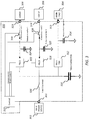
- FIG. 3 is a circuit schematic of a PSU 300 according to example embodiments, which realizes the principles described above in relation to FIGS. 2A and 2B .
- PSUs are available which comprise a plurality of parallel DC-DC converters for suppling respective loads or systems and some of these may not be used or are used for non-critical loads or systems.
- the PSU 300 may comprise an input 301 for receiving supply of power from a main power source 302, for example the power system 108 in FIG. 1 .
- the PSU 300 also comprises a main power supply 312, a secondary power supply 318 and a tertiary power supply 322.
- the primary power supply 312 is connected at its output to a first, or primary, output port 313 to which a primary, or main load 304 may be connected.
- the secondary power supply 318 is connected at its output to a secondary output port 319 to which a secondary load 306 may be connected.
- the tertiary power supply 322 is connected at its output to a tertiary output port 323 to which a tertiary load 308 may be connected.
- the primary power supply 312 may be a regulated power supply, providing a regulated voltage to the main load 304 within predefined voltage tolerance limits. If a secondary load 306 is connected to the secondary output port 319, the same may apply for the secondary power supply 318. If a tertiary load 308 is connected to the tertiary output port 323, the same may apply for the tertiary power supply 322.
- the input to the primary power supply, from the input 301, may comprise a first energy storage module in the form of a capacitor (hereafter referred to as a "tank capacitor") 316 for storing electrical energy. Disposed between the input 301 and a first terminal of the tank capacitor 316 is an input disconnect switch 326. The other terminal of the tank capacitor 316 may be connected to a reference node, such as a ground terminal.
- the outputs of the primary, secondary and tertiary power supplies 312, 318, 322 may comprise respective first, second and third output energy storage modules in the form of capacitors 314, 320, 324 for storing electrical energy.
- first terminals of the first, second and third output capacitors 314, 320, 324 may be connected directly to the outputs of the primary, secondary and tertiary power supplies 312, 318 322 and the other terminals may be connected to a reference node, such as a ground terminal.
- the secondary and tertiary power supplies 318, 322 may be bi-directional. That is, they may be controlled such that current may flow in both directions, i.e. from input to output in a first mode of operation and from output to input in a second mode of operation.
- the direction of current flow may be controlled by a control module 310, the operation of which will be explained later on.
- the control module 310 may also control whether the input disconnect switch 326 is open or closed.
- load disconnect switches 328, 330 Disposed between the outputs of the secondary and tertiary power supplies 318, 322 are respective load disconnect switches 328, 330.
- the control module 310 may also control whether the load disconnect switches 328, 330 are open or closed.
- the input disconnect switch 326, and the load disconnect switches 328, 330 may be any form of electrically controllable switch, such as transistors (bipolar or field-effect transistors) or other solid-state switching components or mechanical components.
- control lines or connectors extend between the control module 310 and the secondary and tertiary power supplies 312, 318, the input disconnect switch 301 and the load disconnect switches 328, 330 to control their respective states.
- each load may comprise one load or multiple loads.
- the reference nodes shown in FIG. 3 may be the same reference node or may be different reference nodes.
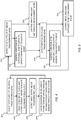
- FIG. 4 there is shown a flow diagram comprising processing operations that may be performed by the control module 310 according to some example embodiments.
- the operations may be performed by hardware, software or a combination thereof.
- the ordering of reference numerals is not necessarily indicative of the order of processing or performance.
- a first operation 401 may comprise detecting the input supply voltage from the main power source 302 being at or above a predetermined level.
- a second operation 402 may comprise causing charging of a secondary energy storage means 320 through the secondary power supply 318.
- a third operation 403 may comprise detecting the input supply voltage being below the predetermined level.
- a fourth operation 404 may comprise causing discharge of the secondary energy storage means 320 through the secondary power supply 318 and into the primary energy storage means 316.
- the process may return to the first operation 401 once the input supply voltage returns.
- FIG. 5 there is shown another flow diagram comprising processing operations that may be performed by the control module 310 according to some example embodiments, with specific example to the PSU 300 shown in FIG. 3 .
- the operations may be performed by hardware, software or a combination thereof.
- the ordering of reference numerals is not necessarily indicative of the order of processing or performance.
- a first operation 501 may comprise detecting the input supply voltage from the main power source 302 being at or above a predetermined level.
- a second operation 502 may comprise controlling the direction of the secondary (and/or tertiary) power supply 318, 322 to operate in an input to output mode.
- a third operation 503, which may be performed substantially simultaneously with the second operation 502, may comprise controlling the input and load switches 326, 328, 330 to be in connect mode.
- the main load 304 is also supplied with sufficient regulated current to operate normally and the tank capacitor 316 is also being charged.
- a fourth operation 504 may comprise detecting the input supply voltage being below the predetermined level.
- a fifth operation 505 may comprise controlling the direction of the secondary (and/or tertiary) power supply 318, 322 to operate in an output to input mode.
- a sixth operation 506, which may be performed substantially simultaneously with the fifth operation 505, may comprise controlling the input and load switches 326, 328, 330 to be in disconnect mode.
- the main load 304 continues to be supplied with sufficient regulated current for a period of time (the hold-up time) to operate normally from the additional charge in the tank capacitor 316 as it discharges to the main load 304.
- the tank capacitor 316 may be configured to have a greater capacity than each of the output capacitors 320, 324.
- the control module 310 may control the PSU 300 remotely, provided a suitably small receiver is placed in the PSU.
- the receiver may be a wireless receiver.
- the amount of memory required to implement an additional control function as described herein may be possible without any further hardware.
- Some proprietary PSUs provide switches for other purposes and hence configuring the PSU to operate in the manner described may be achieved.
- the control module 310 may detect if one or more of the secondary and/or tertiary loads is currently active or non-active, and may utilise the corresponding power supply of a non-active load to discharge harvested power from the output capacitors 320, 324 to the tank capacitor 316.
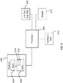
- FIG. 6 is a schematic view of an apparatus which may provide the control module 310 shown in FIG. 3 .
- the apparatus may have a processor 600, a memory 602 closely-coupled to the processor and comprised of a random access memory RAM 604 and read only memory ROM 606.
- the apparatus may comprise an interface 608, and optionally a display 610 and one or more hardware keys 612.
- the apparatus may comprise one or more such interfaces 608 which may comprise a port or bus for connection to the various components under control of the control module 310.
- the apparatus may communicate wirelessly with another module for controlling the various components, or with the various components themselves, in which case the interface 608 may comprise a wireless or network interface
- the one or more wireless or network interfaces 608 may be for connection to the internet, e.g. using WiFi or similar.
- the processor 600 is connected to each of the other components in order to control operation thereof.
- the memory 602 may comprise a non-volatile memory, a hard disk drive (HDD) or a solid state drive (SSD).
- the ROM 606 of the memory stores, amongst other things, an operating system 614 and may store one or more software applications 616.
- the RAM 604 of the memory 602 may be used by the processor 600 for the temporary storage of data.
- the operating system 614 may contain code which, when executed by the processor 600, implements the operations as described above, for example in the various flow diagrams of FIGS 4 and 5 .
- the memory 602 may comprise any suitable form, and may even be implemented in the cloud.
- the processor 600 may take any suitable form.
- the processor 600 may be a microcontroller, plural microcontrollers, a microprocessor, or plural microprocessors and the processor may comprise processor circuitry.
- FIG. 7A and FIG. 7B show tangible non-volatile media, respectively a removable memory unit 700 and a compact disc (CD) 701, each storing computer-readable code which when run by a computer may perform methods according to example embodiments described above.
- the removable memory unit 700 may be a memory stick, e.g. a USB memory stick, having internal memory 703 storing the computer-readable code.
- the internal memory 703 may be accessed by a computer system via a connector 704.
- the CD 701 may be a CD-ROM or a DVD or similar. Other forms of tangible storage media may be used.
- any reference to “means” may refer to the means as comprising: analog circuitry, digital circuitry, a combination or analog and digital circuitry, and/or at least one processor, and at least one memory including computer program code, the at least one memory and computer program code configured to, with the at least one processor, cause the performance of the apparatus.
- Implementations of any of the above described blocks, apparatuses, systems, techniques or methods include, as non-limiting examples, implementations as hardware, software, firmware, special purpose circuits or logic, general purpose hardware or controller or other computing devices, or some combination thereof. Some example embodiments may be implemented in the cloud and utilize virtualized modules.
- Example embodiments of the present invention may be implemented in software, hardware, application logic or a combination of software, hardware and application logic.
- the software, application logic and/or hardware may reside on memory, or any computer media.
- the application logic, software or an instruction set is maintained on any one of various conventional computer-readable media.
- a "memory" or “computer-readable medium” may be any non-transitory media or means that can contain, store, communicate, propagate or transport the instructions for use by or in connection with an instruction execution system, apparatus, or device, such as a computer.
- references to, where relevant, "computer-readable storage medium”, “computer program product”, “tangibly embodied computer program” etc., or a “processor” or “processing circuitry” etc. should be understood to encompass not only computers having differing architectures such as single/multi-processor architectures and sequencers/parallel architectures, but also specialised circuits such as field programmable gate arrays FPGA, application specify circuits ASIC, signal processing devices and other devices.
- References to computer program, instructions, code etc. should be understood to express software for a programmable processor firmware such as the programmable content of a hardware device as instructions for a processor or configured or configuration settings for a fixed function device, gate array, programmable logic device, etc.
- circuitry refers to all of the following: (a) hardware-only circuit implementations (such as implementations in analogue and/or digital circuitry) and (b) to combinations of circuits and software (and/or firmware), such as (as applicable): (i) to a combination of processor(s) or (ii) to portions of processor(s)/software (including digital signal processor(s)), software, and memory(ies) that work together to cause an apparatus, such as a server, to perform various functions) and (c) to circuits, such as a microprocessor(s) or a portion of a microprocessor(s), that require software or firmware for operation, even if the software or firmware is not physically present.
Landscapes
- Engineering & Computer Science (AREA)
- Power Engineering (AREA)
- Business, Economics & Management (AREA)
- Emergency Management (AREA)
- Charge And Discharge Circuits For Batteries Or The Like (AREA)
Abstract
Description
- Example embodiments relate to methods and systems for controlling the hold-up time in a power supply.
- Hold-up time is the length of time that a power supply unit (PSU) can operate in a regulated way, e.g. within a specified range, after failure or fluctuation of its input supply. For example, the hold-up time of a 10 volt DC PSU with +/- 10% regulation is the duration of the time between the input being removed and the output falling to 9 volts.
- Equipment comprising components, such as processors, memories etc. may lose critical data if there is even a momentary loss of power. This may lead to critical failures in the functioning of the system unless the PSUs can cater for such power losses. In the telecommunications sector, PSUs may be used for all manner of communications systems. For example, a remote radio head (RRH) is a remote radio transceiver that may be used to extend the coverage of base stations in challenging environments. RRHs require a regulated PSU with appropriate hold-up time to cater for brief losses of power. Otherwise, there may be a loss of service, possibly requiring an engineer to travel to the site of the RRH to repair or replace it.
- Embodiments herein are not limited to telecommunications systems.
- According to a first example embodiment, there is provided an apparatus comprising: means for providing a supply voltage to a primary load from a primary energy storage means; means for detecting an input supply voltage provided by a main power supply; means for causing charging of a secondary energy storage means from the main power supply through a secondary power supply if the input supply voltage is at or above a predetermined level, wherein the secondary power supply is configured to operate in a first mode of operation; and means for causing discharging of the secondary energy storage means through the secondary power supply into the primary energy storage if the input supply voltage is below the predetermined level, wherein the secondary power supply is configured to operate in a second mode of operation.
- The secondary power supply may be a DC-DC power converter.
- The direction of energy flow may be determined by a controlling means which, in the first mode of operation, directs energy in a first direction from the input to the output to charge the secondary energy storage means and, in the second mode of operation, directs energy in a second direction from the output to the input to cause discharge energy from the secondary energy storage means to charge the primary energy storage means.
- The apparatus may further comprise a first switching means connected between the secondary energy storage means and a secondary load connected to an output of the secondary power supply, and further comprising controlling means configured, by control of the first switching means, to disconnect the secondary load from the secondary energy storage means when the input supply is below the predetermined level in the second mode of operation.
- The apparatus may further comprise a second switching means connected between the main power supply and inputs of the voltage supply means to the primary load and the secondary power supply, and further comprising controlling means configured, by control of the switching means, to disconnect the main power supply from the first and second inputs means when the input supply is below the predetermined level in the second mode of operation.
- The primary energy storage means may be connected directly to the main power supply.
- The primary energy storage means may have greater storage capacity than the secondary energy storage means.
- The primary energy storage means and the secondary energy storage means may comprise capacitors.
- The apparatus may comprise a plurality of secondary, additional power supply means, each for connection to respective secondary loads, each second input being connected to the main power supply and the primary energy storage means and having respective secondary energy storage means connected between their outputs and a reference node, and further comprising controlling means configured to cause charging of each secondary energy storage means when the input voltage supply is at or above the predetermined level in the first mode of operation and to cause discharging, through the respective power supplies, into the first energy storage means, when the input supply is below the predetermined level in the second mode of operation.
- The power supplies may be connected in parallel to one another.
- According to a second example embodiment, there may be provided a method, comprising: providing a supply voltage to a primary load from a primary energy storage means; detecting an input supply voltage provided by a main power supply; causing charging of a secondary energy storage from the main power supply through a secondary power supply, if the input supply voltage is at or above a predetermined level, wherein the secondary power supply is configured to operate in a first mode of operation; and causing discharging of the secondary energy storage through the secondary power supply into the primary energy storage, if the input supply voltage is below the predetermined level, wherein the secondary power supply is configured to operate in a second mode of operation.
- The secondary power supply may be a bi-directional DC-DC power converter, and the method comprises, in the first mode of operation, directing energy in a first direction from the input to the output to charge the secondary energy storage means and, in the second mode of operation, directing energy in a second direction from the output to the input to cause discharged energy from the secondary energy storage means to charge the primary energy storage means.
- The method may further comprise controlling a first switching means between the secondary energy storage means and a secondary load to disconnect the secondary load from the secondary energy storage means when the input supply voltage is below the predetermined level in the second mode of operation.
- The method may further comprise controlling a second switching means connected between the main power supply and inputs of the voltage supply means to the primary load and the secondary power supply, and further comprising controlling means for disconnecting the main power supply from the first and second inputs means when the input supply is below the predetermined level in the second mode of operation.
- According to a third example embodiment, there may be provided a computer program product comprising at least one non-transitory computer-readable storage medium having computer-executable program code portions stored therein, the computer-executable program code portions comprising program code instructions for: providing a supply voltage to a primary load from a primary energy storage means; detecting an input supply voltage provided by a main power supply; causing charging of a secondary energy storage from the main power supply through a secondary power supply, if the input supply voltage is at or above a predetermined level, wherein the secondary power supply is configured to operate in a first mode of operation; and causing discharging of the secondary energy storage through the secondary power supply into the primary energy storage, if the input supply voltage is below the predetermined level, wherein the secondary power supply is configured to operate in a second mode of operation.
- According to a fourth example embodiment, there may be provided a non-transitory computer readable medium comprising program instructions stored thereon for performing a method, comprising: providing a supply voltage to a primary load from a primary energy storage means; detecting an input supply voltage provided by a main power supply; causing charging of a secondary energy storage from the main power supply through a secondary power supply, if the input supply voltage is at or above a predetermined level, wherein the secondary power supply is configured to operate in a first mode of operation; and causing discharging of the secondary energy storage through the secondary power supply into the primary energy storage, if the input supply voltage is below the predetermined level, wherein the secondary power supply is configured to operate in a second mode of operation.
- According to a fifth example embodiment, there may be provided an apparatus comprising: at least one processor; and at least one memory including computer program code which, when executed by the at least one processor, causes the apparatus: to provide a supply voltage to a primary load from a primary energy storage means; to detect an input supply voltage provided by a main power supply; to cause charging of a secondary energy storage from the main power supply through a secondary power supply, if the input supply voltage is at or above a predetermined level, wherein the secondary power supply is configured to operate in a first mode of operation; and to cause discharging of the secondary energy storage through the secondary power supply into the primary energy storage, if the input supply voltage is below the predetermined level, wherein the secondary power supply is configured to operate in a second mode of operation.
- According to a sixth example embodiment, there may be provided a means for providing a primary, main DC power supply, to a first output, the primary means having a first input connectable to a DC input supply and to an associated primary energy storage means connected between the first input and a reference node, the first output of the primary means being for connection to a primary load; means for providing an secondary, additional DC power supply to a second output, the secondary means having a second input connected to the same DC input supply and to the primary energy storage means and having a secondary energy storage means connected between the output of the secondary power supply and a reference node, the secondary output being suitable for connection to a secondary load; and means for controlling charging and discharging of the secondary energy storage means, the controlling means causing charging of the secondary energy storage means through the secondary power supply when the input supply is at or above a predetermined level and causing discharging of the secondary energy storage means, through the second power supply, and into the first energy storage means, when the input supply is below the predetermined level.
- According to a seventh example embodiment, there may be provided a method, comprising: controlling an apparatus comprising a primary DC power supply and a secondary DC power supply, in which the primary power supply has a first input connectable to a DC input supply and to an associated primary energy storage means connected between the first input and a reference node and a first output for connection to a primary load, and in which the secondary power supply has a second input connected to the same DC input supply and to the primary energy storage means and a secondary energy storage means connected between the output of the secondary power supply and the reference node, wherein the controlling comprises charging and discharging of the secondary energy storage means by charging of the secondary energy storage means through the secondary power supply when the input supply is at or above a predetermined level and discharging of the secondary energy storage means, through the second power supply, and into the primary energy storage means, when the input supply is below the predetermined level.
- In the foregoing, any reference to "means" may refer to the means as comprising: analog circuitry, digital circuitry, a combination or analog and digital circuitry, and/or at least one processor, and at least one memory including computer program code, the at least one memory and computer program code configured to, with the at least one processor, cause the performance of the apparatus.
- Example embodiments will now be described, by way of non-limiting example, with reference to the accompanying drawings, in which:
-
FIG. 1 is a schematic view of a communications mast, associated with a base station and power system, for which example embodiments may be usefully applied; -
FIGS. 2A - 2B are schematic circuits indicating respective modes of operation for extending a hold-up time of a power supply in accordance with example embodiments; -
FIG. 3 is a more detailed circuit for extending a hold-up time of a power supply in accordance with example embodiments; -
FIG. 4 is a flow diagram indicating operations that may be performed by circuitry, logic and/or computer program code in accordance with example embodiments; -
FIG. 5 is a more detailed flow diagram indicating operations that may be performed by circuitry, logic and/or computer program code in accordance with example embodiments; -
FIG. 6 is a schematic block diagram of components of an apparatus that may perform theFIG. 4 and FIG. 5 operations; and -
FIGS. 7A - 7B are non-transitory storage media for storing computer code that may perform theFIG. 4 and FIG. 5 operations. - Example embodiments relate to an apparatus and methods for controlling the hold-up time in a power supply unit (PSU). For example, some example embodiments relate to extending the hold-up time in a PSU.
- In this context, a PSU may comprise one or more constituent power supplies, or sub PSUs, that may supply power to respective loads. For example, the overall PSU may be termed the PSU and the power supplies within the PSU may be sub-supplies or power converters, e.g. DC-DC converters.
- A DC-DC converter is an electrical or electronic circuit that converts a source of direct current (DC), usually from one voltage to another voltage. There may be a supply of input DC power to one or more DC-DC converters, or input AC power that is first rectified, and the DC converter converts and regulates the output voltage to a level appropriate for its associated load. Sometimes, a PSU may comprise a plurality of sub PSUs, for example a plurality of DC-DC converters, each for suppling a respective regulated output voltage to a plurality of loads. The plurality of sub PSUs may be electrically in parallel. Sometimes, one or more of the sub PSUs may not be connected to a load or may not be used in respect of a connected load for a period of time. For example, a sub PSU may be connected to a non-critical load that gathers data very occasionally, or which gathers and stores data but transmits that data very occasionally. In other words, a non-critical load may be considered one that does not require a constant, regulated power source to perform its function correctly or for a critical purpose.
- A load may mean any electrical or electronic component that requires power to perform a technical function.
- Embodiments herein may involve utilising one converter, or primary converter, to supply power to a main load and another converter, or secondary converter, to be used in controlling the hold-up time for the power supplied to the main load. The secondary converter may or may not be connected to a secondary load. Where it is connected to a secondary load, use of the secondary converter in accordance with example embodiments, may be performed at a time when the secondary load is not being used for gathering, processing and/or transmitting data or signals.
- Some PSUs are provided which contain multiple such power converters (sub PSUs) in parallel for connection to respective loads on-site. Therefore, adaption of such PSUs to operate in accordance with example embodiments is envisaged as an option, and this may involve providing additional functionality. Sometimes, PSUs may be provided with in-built processing functionality and/or electrically controlled switches, and hence embodiments herein may utilise such PSUs without requiring additional components. Sometimes, PSUs may be provided with output energy storage modules (e.g. capacitors) which may be utilised herein. Therefore, embodiments may make use of redundant components and circuitry already provided in such PSUs or systems which incorporate such PSU's.
- Practical uses of PSUs according to example embodiments include any application that requires a regulated and known source of power notwithstanding the possibility of even short losses of the input supply. Such losses may be complete losses (zero input) or a drop below a level that results in the output power from one or more converters being below the required level(s). Where the effect of such a loss may affect the load or subsequent functionality, there needs to be a way of mitigating the problem. For example, equipment comprising digital components, such as processors, memories etc. may lose critical data if there is even a momentary loss of power. This can lead to critical failures in the functioning of the system unless the PSUs can cater for such power losses. In the telecommunications sector, PSUs may be used for all manner of communications systems. For example, a remote radio head (RRH) is a remote radio transceiver that may be used to extend the coverage of base stations in challenging environments. Example embodiments are not limited to such.
- For example,
FIG. 1 shows atelecommunications mast 100 on which is mounted one ormore antennas 102, and further comprising at least oneRRH 104 which is electrically connected to abase station 106 andpower system 108 on the ground. Theantennas 102,RRH 104 andbase station 106 may be for any suitable radio technology, such as 3G, 4G, LTE, 5G or indeed any future radio technology. TheRRH 104 provides a separation of signal and power components from thebase station 106, which is on the ground, and the RRH sits close to theantennas 102. - Within the
RRH 104 there may be aPSU 110 which receives an input supply voltage and current from thepower system 108. ThePSU 110 may comprise a plurality of sub-PSUs, e.g. DC-DC power converters, at least one of which is connected to, and supplies, power to critical components also housed in theRRH 104. The critical components may comprise one or more of RF circuitry, analog-to-digital converters (ADCs), digital-to-analog converters (DACs), RF up converters, RF downconverters, mixers, microprocessors and so on. One or more other sub PSUs may be redundant, or only used periodically, or may be used with non-critical modules. - For example, the
PSU 110 may comprise a sub PSU for digital parts of theRRH 104, considered critical, and other sub PSUs may be for power amplifiers and so on. These sub PSUs may be located on the same printed wire board (PWB) but might be provided as separate units. A control means may also be provided in theRRH 104. Embodiments herein make use of these other sub PSUs to extend the hold-up time for the sub PSUs for the one or more critical components, thus mitigating and/or avoiding problems that may be caused if thepower system 108 were to fail or drop in voltage, or indeed if the mains supply to thepower system 108 were to fail or drop in voltage. - In some cases, if the
power system 108 were to fail or drop, critical components such as digital parts of, e.g., radios, processors etc. may be configured to perform a controlled, fast shut-down procedure, including sending power down alerts to back-end systems, saving important data and /or log files in non-volatile memory. Extending the hold-up time may therefore, in addition to maintaining power for momentary losses or drops, provide sufficient time for the critical components to perform the controlled shut-down procedure if the loss is more than momentary. Power amplifiers, connected to other sub PSUs, are not needed during the shut-down and hence example embodiments may involve taking energy stored via other sub PSUs for use by the primary PSU. -
FIGS. 2A and 2B show anexample overview PSU 200 according to example embodiments, in two stages of operation. - Referring first to
FIG. 2A , thePSU 200 comprises aninput 201 for receiving a supply of power from amain power source 202, for example thepower system 108 inFIG. 1 . ThePSU 200 also comprises aprimary power supply 204 and asecondary power supply 206. Theprimary power supply 204 is connected at its output to a first, or primary,output port 208 to which aprimary load 210 may be connected. Thesecondary power supply 206 is connected at its output to asecondary output port 212 to which asecondary load 214 may be connected. Theprimary power supply 204 may be a regulated power supply, providing a regulated voltage to theprimary load 210. The voltage provided by theprimary power supply 204 may be within predefined tolerance limits. If asecondary load 214 is connected to thesecondary output port 212, the same may apply for thesecondary power supply 206, i.e. thesecondary power supply 206 may be a regulated power supply, providing a regulated voltage to thesecondary load 214. The voltage provided by thesecondary power supply 206 may be within predefined tolerance limits. The tolerance limits of the voltages provided by the primary and secondary power supplies may be same or different. - The input to the
primary power supply 204, from theinput 201, may comprise a firstenergy storage module 220 for storing electrical energy. For example, the firstenergy storage module 220 may comprise a capacitor. One terminal of the firstenergy storage module 220 may be connected to theinput 201 and the other terminal may be connected to a reference node, such as a ground terminal. The outputs of the primary andsecondary power supplies energy storage modules energy storage modules secondary power supplies energy storage modules energy storage modules outputs secondary power supplies FIGS. 2A and 2B may be the same reference node or may be different reference nodes. - The
secondary power supply 206 may be bi-directional. That is, it may be controlled such that current may flow in both directions, i.e. from input to output in a first mode of operation (indicated inFIG. 2A ) and from output to input in a second mode of operation (indicated inFIG. 2B ). Acontrol line 220 is shown extended from acontroller module 222 which provides control logic, and may at least control the direction of current flow for thesecondary power supply 206. - Therefore, referring first to
FIG. 2A , when themain power source 202 is supplying power to thePSU 200 at a sufficient level to provide correct power to theprimary load 210, some current flows through thesecondary power supply 206 and charge is stored by the thirdenergy storage module 218 at the output. The firstenergy storage module 220 and thesecond energy storage 216 may also be charged. - Referring now to
FIG. 2B , when themain power source 202 is interrupted in terms of input power, as represented by the power source being shown disconnected from the rest of the circuit, example embodiments involve re-routing the charge stored on the thirdenergy storage module 218, by changing the mode (and hence direction) of the bi-directionalsecondary power supply 206, to provide power to theprimary power supply 204 and/or to charge the firstenergy storage module 220. Theprimary power supply 204 may take current from whichever source is more capable of supplying it, depending on the current discharge state of the firstenergy storage module 220 and that of thesecondary power supply 206. The current can be taken from either or both. Thus, theprimary power supply 204 may continue its operation to supply sufficient regulated power to theprimary load 210 using discharged energy from the firstenergy storage module 220, which has its hold-up time extended by the additional received charge, and/or that of thesecondary power supply 206. - Other example embodiments may provide any number of secondary-
type power supplies 206 connected in parallel as shown, and operated in the same way to provide additional charge to the firstenergy storage module 220, and therefore extend the hold-up time even further. - The first
energy storage module 220 may have a larger capacity than the second and thirdenergy storage modules - This arrangement does not require any significant change to existing PSUs, nor additional bulky components, and therefore it may offer a convenient solution, particularly in space-limited situations. Also, there is no requirement to have
secondary loads 214 actually connected to thePSU 200. In practice, many PSUs come off-the-shelf with parallel sub PSUs, and often some of these may be redundant and/or provide power to non-critical loads or systems. -
FIG. 3 is a circuit schematic of aPSU 300 according to example embodiments, which realizes the principles described above in relation toFIGS. 2A and 2B . As mentioned above, PSUs are available which comprise a plurality of parallel DC-DC converters for suppling respective loads or systems and some of these may not be used or are used for non-critical loads or systems. - Referring to
FIG. 3 , thePSU 300 may comprise aninput 301 for receiving supply of power from amain power source 302, for example thepower system 108 inFIG. 1 . ThePSU 300 also comprises amain power supply 312, asecondary power supply 318 and atertiary power supply 322. Theprimary power supply 312 is connected at its output to a first, or primary,output port 313 to which a primary, ormain load 304 may be connected. Thesecondary power supply 318 is connected at its output to asecondary output port 319 to which asecondary load 306 may be connected. Thetertiary power supply 322 is connected at its output to atertiary output port 323 to which atertiary load 308 may be connected. - The
primary power supply 312 may be a regulated power supply, providing a regulated voltage to themain load 304 within predefined voltage tolerance limits. If asecondary load 306 is connected to thesecondary output port 319, the same may apply for thesecondary power supply 318. If atertiary load 308 is connected to thetertiary output port 323, the same may apply for thetertiary power supply 322. - The input to the primary power supply, from the
input 301, may comprise a first energy storage module in the form of a capacitor (hereafter referred to as a "tank capacitor") 316 for storing electrical energy. Disposed between theinput 301 and a first terminal of thetank capacitor 316 is aninput disconnect switch 326. The other terminal of thetank capacitor 316 may be connected to a reference node, such as a ground terminal. The outputs of the primary, secondary andtertiary power supplies capacitors third output capacitors tertiary power supplies - The secondary and
tertiary power supplies control module 310, the operation of which will be explained later on. Thecontrol module 310 may also control whether theinput disconnect switch 326 is open or closed. - Disposed between the outputs of the secondary and
tertiary power supplies control module 310 may also control whether the load disconnect switches 328, 330 are open or closed. - The
input disconnect switch 326, and the load disconnect switches 328, 330 may be any form of electrically controllable switch, such as transistors (bipolar or field-effect transistors) or other solid-state switching components or mechanical components. - As will be seen from
FIG. 3 , control lines or connectors extend between thecontrol module 310 and the secondary andtertiary power supplies input disconnect switch 301 and the load disconnect switches 328, 330 to control their respective states. - In
FIG. 2A, FIG. 2B , andFIG. 3 the loads have been illustrated as one module, i.e. primary load, secondary load, load3, load2, main load. Each load may comprise one load or multiple loads. - The reference nodes shown in
FIG. 3 may be the same reference node or may be different reference nodes. - Referring now to
FIG. 4 , there is shown a flow diagram comprising processing operations that may be performed by thecontrol module 310 according to some example embodiments. The operations may be performed by hardware, software or a combination thereof. The ordering of reference numerals is not necessarily indicative of the order of processing or performance. - A
first operation 401 may comprise detecting the input supply voltage from themain power source 302 being at or above a predetermined level. - A
second operation 402 may comprise causing charging of a secondary energy storage means 320 through thesecondary power supply 318. - A
third operation 403 may comprise detecting the input supply voltage being below the predetermined level. - A
fourth operation 404 may comprise causing discharge of the secondary energy storage means 320 through thesecondary power supply 318 and into the primary energy storage means 316. - The process may return to the
first operation 401 once the input supply voltage returns. - Referring now to
FIG. 5 , there is shown another flow diagram comprising processing operations that may be performed by thecontrol module 310 according to some example embodiments, with specific example to thePSU 300 shown inFIG. 3 . The operations may be performed by hardware, software or a combination thereof. The ordering of reference numerals is not necessarily indicative of the order of processing or performance. - A
first operation 501 may comprise detecting the input supply voltage from themain power source 302 being at or above a predetermined level. - A
second operation 502 may comprise controlling the direction of the secondary (and/or tertiary)power supply - A
third operation 503, which may be performed substantially simultaneously with thesecond operation 502, may comprise controlling the input andload switches - With reference to
FIG. 3 , this means that the secondary and/ortertiary power supplies output capacitors tertiary loads output ports main load 304 is also supplied with sufficient regulated current to operate normally and thetank capacitor 316 is also being charged. - A
fourth operation 504 may comprise detecting the input supply voltage being below the predetermined level. - A
fifth operation 505 may comprise controlling the direction of the secondary (and/or tertiary)power supply - A
sixth operation 506, which may be performed substantially simultaneously with thefifth operation 505, may comprise controlling the input andload switches - With reference to
FIG. 5 , this means that the secondary and/or tertiarybi-directional power supplies output capacitors tertiary loads output ports main load 304 continues to be supplied with sufficient regulated current for a period of time (the hold-up time) to operate normally from the additional charge in thetank capacitor 316 as it discharges to themain load 304. - The
tank capacitor 316 may be configured to have a greater capacity than each of theoutput capacitors - As mentioned previously, in some cases, there may be no loads connected to one or more of the secondary and
tertiary power supplies PSU 300 may comprise multiple power supplies connected in parallel in a single proprietary unit, and only a subset is needed, possibly only one for the main, primary load. Therefore, using such aPSU 300 in the manner described makes use of otherwise wasted resources by providing thecontrol module 310. This may minimise space and may occupy the same space as the original unit, not requiring additional and possibly bulky components. In some cases, thecontrol module 310 may control thePSU 300 remotely, provided a suitably small receiver is placed in the PSU. The receiver may be a wireless receiver. In some cases, where there is a processor and memory already provided in the PSU, e.g. for other purposes, the amount of memory required to implement an additional control function as described herein may be possible without any further hardware. Some proprietary PSUs provide switches for other purposes and hence configuring the PSU to operate in the manner described may be achieved. - Further, even if there are loads connected to one or more of the secondary and
tertiary power supplies respective loads control module 310 may detect if one or more of the secondary and/or tertiary loads is currently active or non-active, and may utilise the corresponding power supply of a non-active load to discharge harvested power from theoutput capacitors tank capacitor 316. -
FIG. 6 is a schematic view of an apparatus which may provide thecontrol module 310 shown inFIG. 3 . - The apparatus may have a
processor 600, amemory 602 closely-coupled to the processor and comprised of a randomaccess memory RAM 604 and read onlymemory ROM 606. The apparatus may comprise aninterface 608, and optionally adisplay 610 and one ormore hardware keys 612. The apparatus may comprise one or moresuch interfaces 608 which may comprise a port or bus for connection to the various components under control of thecontrol module 310. In some embodiments, the apparatus may communicate wirelessly with another module for controlling the various components, or with the various components themselves, in which case theinterface 608 may comprise a wireless or network interface The one or more wireless ornetwork interfaces 608 may be for connection to the internet, e.g. using WiFi or similar. Theprocessor 600 is connected to each of the other components in order to control operation thereof. - The
memory 602 may comprise a non-volatile memory, a hard disk drive (HDD) or a solid state drive (SSD). TheROM 606 of the memory stores, amongst other things, anoperating system 614 and may store one ormore software applications 616. TheRAM 604 of thememory 602 may be used by theprocessor 600 for the temporary storage of data. Theoperating system 614 may contain code which, when executed by theprocessor 600, implements the operations as described above, for example in the various flow diagrams ofFIGS 4 and 5 . As mentioned below, thememory 602 may comprise any suitable form, and may even be implemented in the cloud. - The
processor 600 may take any suitable form. For instance, theprocessor 600 may be a microcontroller, plural microcontrollers, a microprocessor, or plural microprocessors and the processor may comprise processor circuitry. -
FIG. 7A and FIG. 7B show tangible non-volatile media, respectively aremovable memory unit 700 and a compact disc (CD) 701, each storing computer-readable code which when run by a computer may perform methods according to example embodiments described above. Theremovable memory unit 700 may be a memory stick, e.g. a USB memory stick, havinginternal memory 703 storing the computer-readable code. Theinternal memory 703 may be accessed by a computer system via aconnector 704. TheCD 701 may be a CD-ROM or a DVD or similar. Other forms of tangible storage media may be used. - In the foregoing, any reference to "means" may refer to the means as comprising: analog circuitry, digital circuitry, a combination or analog and digital circuitry, and/or at least one processor, and at least one memory including computer program code, the at least one memory and computer program code configured to, with the at least one processor, cause the performance of the apparatus.
- Implementations of any of the above described blocks, apparatuses, systems, techniques or methods include, as non-limiting examples, implementations as hardware, software, firmware, special purpose circuits or logic, general purpose hardware or controller or other computing devices, or some combination thereof. Some example embodiments may be implemented in the cloud and utilize virtualized modules.
- Example embodiments of the present invention may be implemented in software, hardware, application logic or a combination of software, hardware and application logic. The software, application logic and/or hardware may reside on memory, or any computer media. In an example embodiment, the application logic, software or an instruction set is maintained on any one of various conventional computer-readable media. In the context of this document, a "memory" or "computer-readable medium" may be any non-transitory media or means that can contain, store, communicate, propagate or transport the instructions for use by or in connection with an instruction execution system, apparatus, or device, such as a computer.
- Reference to, where relevant, "computer-readable storage medium", "computer program product", "tangibly embodied computer program" etc., or a "processor" or "processing circuitry" etc. should be understood to encompass not only computers having differing architectures such as single/multi-processor architectures and sequencers/parallel architectures, but also specialised circuits such as field programmable gate arrays FPGA, application specify circuits ASIC, signal processing devices and other devices. References to computer program, instructions, code etc. should be understood to express software for a programmable processor firmware such as the programmable content of a hardware device as instructions for a processor or configured or configuration settings for a fixed function device, gate array, programmable logic device, etc.
- As used in this application, the term "circuitry" refers to all of the following: (a) hardware-only circuit implementations (such as implementations in analogue and/or digital circuitry) and (b) to combinations of circuits and software (and/or firmware), such as (as applicable): (i) to a combination of processor(s) or (ii) to portions of processor(s)/software (including digital signal processor(s)), software, and memory(ies) that work together to cause an apparatus, such as a server, to perform various functions) and (c) to circuits, such as a microprocessor(s) or a portion of a microprocessor(s), that require software or firmware for operation, even if the software or firmware is not physically present.
- In this brief description, reference has been made to various examples. The description of features or functions in relation to an example indicates that those features or functions are present in that example. The use of the term 'example' or 'for example' or 'may' in the text denotes, whether explicitly stated or not, that such features or functions are present in at least the described example, whether described as an example or not, and that they can be, but are not necessarily, present in some of or all other examples. Thus 'example', 'for example' or 'may' refers to a particular instance in a class of examples. A property of the instance can be a property of only that instance or a property of the class or a property of a sub-class of the class that includes some but not all of the instances in the class. It is therefore implicitly disclosed that a features described with reference to one example but not with reference to another example, can where possible be used in that other example but does not necessarily have to be used in that other example.
- Although embodiments of the present invention have been described in the preceding paragraphs with reference to various examples, it should be appreciated that modifications to the examples given can be made without departing from the scope of the invention as claimed.
- Features described in the preceding description may be used in combinations other than the combinations explicitly described.
- Although functions have been described with reference to certain features, those functions may be performable by other features whether described or not.
- Although features have been described with reference to certain embodiments, those features may also be present in other embodiments whether described or not.
- Whilst endeavouring in the foregoing specification to draw attention to those features of the invention believed to be of particular importance it should be understood that the Applicant claims protection in respect of any patentable feature or combination of features hereinbefore referred to and/or shown in the drawings whether or not particular emphasis has been placed thereon.
Claims (15)
- Apparatus comprising:means for providing a supply voltage to a primary load from a primary energy storage means;means for detecting an input supply voltage provided by a main power supply;means for causing charging of a secondary energy storage means from the main power supply through a secondary power supply if the input supply voltage is at or above a predetermined level, wherein the secondary power supply is configured to operate in a first mode of operation; andmeans for causing discharging of the secondary energy storage means through the secondary power supply into the primary energy storage if the input supply voltage is below the predetermined level, wherein the secondary power supply is configured to operate in a second mode of operation.
- The apparatus of claim 1, wherein the secondary power supply is a DC-DC power converter.
- The apparatus of claim 2, wherein the direction of energy flow is determined by a controlling means which, in the first mode of operation, directs energy in a first direction from the input to the output to charge the secondary energy storage means and, in the second mode of operation, directs energy in a second direction from the output to the input to cause discharge energy from the secondary energy storage means to charge the primary energy storage means.
- The apparatus of any preceding claim, further comprising a first switching means connected between the secondary energy storage means and a secondary load connected to an output of the secondary power supply, and further comprising controlling means configured, by control of the first switching means, to disconnect the secondary load from the secondary energy storage means when the input supply is below the predetermined level in the second mode of operation.
- The apparatus of any preceding claim, further comprising a second switching means connected between the main power supply and inputs of the voltage supply means to the primary load and the secondary power supply, and further comprising controlling means configured, by control of the switching means, to disconnect the main power supply from the first and second inputs means when the input supply is below the predetermined level in the second mode of operation.
- The apparatus of any preceding claim, wherein the primary energy storage means is connected directly to the main power supply.
- The apparatus of any preceding claim, wherein the primary energy storage means has greater storage capacity than the secondary energy storage means.
- The apparatus of any preceding claim, wherein the primary energy storage means and the secondary energy storage means are capacitors.
- The apparatus of any preceding claim, comprising a plurality of secondary, additional power supply means, each for connection to respective secondary loads, each second input being connected to the main power supply and the primary energy storage means and having respective secondary energy storage means connected between their outputs and a reference node, and further comprising controlling means configured to cause charging of each secondary energy storage means when the input voltage supply is at or above the predetermined level in the first mode of operation and to cause discharging, through the respective power supplies, into the first energy storage means, when the input supply is below the predetermined level in the second mode of operation.
- The apparatus of any preceding claim, wherein the power supplies are connected in parallel to one another.
- A method, comprising:providing a supply voltage to a primary load from a primary energy storage means;detecting an input supply voltage provided by a main power supply;causing charging of a secondary energy storage from the main power supply through a secondary power supply, if the input supply voltage is at or above a predetermined level, wherein the secondary power supply is configured to operate in a first mode of operation; andcausing discharging of the secondary energy storage through the secondary power supply into the primary energy storage, if the input supply voltage is below the predetermined level, wherein the secondary power supply is configured to operate in a second mode of operation.
- The method of claim 11, wherein the secondary power supply is a bi-directional DC-DC power converter, and the method comprises, in the first mode of operation, directing energy in a first direction from the input to the output to charge the secondary energy storage means and, in the second mode of operation, directing energy in a second direction from the output to the input to cause discharged energy from the secondary energy storage means to charge the primary energy storage means.
- The method of claim 11 or claim 12, further comprising controlling a first switching means between the secondary energy storage means and a secondary load to disconnect the secondary load from the secondary energy storage means when the input supply voltage is below the predetermined level in the second mode of operation.
- The method of any of claims 11 to 13, further comprising controlling a second switching means connected between the main power supply and inputs of the voltage supply means to the primary load and the secondary power supply, and further comprising controlling means for disconnecting the main power supply from the first and second inputs means when the input supply is below the predetermined level in the second mode of operation.
- A computer program product comprising at least one non-transitory computer-readable storage medium having computer-executable program code portions stored therein, the computer-executable program code portions comprising program code instructions for:providing a supply voltage to a primary load from a primary energy storage means;detecting an input supply voltage provided by a main power supply;causing charging of a secondary energy storage from the main power supply through a secondary power supply, if the input supply voltage is at or above a predetermined level, wherein the secondary power supply is configured to operate in a first mode of operation; andcausing discharging of the secondary energy storage through the secondary power supply into the primary energy storage, if the input supply voltage is below the predetermined level, wherein the secondary power supply is configured to operate in a second mode of operation.
Priority Applications (1)
| Application Number | Priority Date | Filing Date | Title |
|---|---|---|---|
| EP19162958.3A EP3709479A1 (en) | 2019-03-14 | 2019-03-14 | Controlling hold-up time in power supply |
Applications Claiming Priority (1)
| Application Number | Priority Date | Filing Date | Title |
|---|---|---|---|
| EP19162958.3A EP3709479A1 (en) | 2019-03-14 | 2019-03-14 | Controlling hold-up time in power supply |
Publications (1)
| Publication Number | Publication Date |
|---|---|
| EP3709479A1 true EP3709479A1 (en) | 2020-09-16 |
Family
ID=65817825
Family Applications (1)
| Application Number | Title | Priority Date | Filing Date |
|---|---|---|---|
| EP19162958.3A Withdrawn EP3709479A1 (en) | 2019-03-14 | 2019-03-14 | Controlling hold-up time in power supply |
Country Status (1)
| Country | Link |
|---|---|
| EP (1) | EP3709479A1 (en) |
Citations (4)
| Publication number | Priority date | Publication date | Assignee | Title |
|---|---|---|---|---|
| US20060146461A1 (en) * | 2005-01-06 | 2006-07-06 | Jones Carl E | Apparatus, system, and method for maximizing power system holdup time during loss of input power |
| US20120139515A1 (en) * | 2010-12-01 | 2012-06-07 | Delta Electronics, Inc. | Power supply apparatus and power supply system with plural power supply apparatuses |
| US20170012550A1 (en) * | 2015-07-08 | 2017-01-12 | Toshiba Mitsubishi-Electric Industrial Systems Corporation | Power conversion system including plurality of power converters connected in parallel to load |
| US20170031410A1 (en) * | 2015-07-30 | 2017-02-02 | Dell Products L.P. | Systems and methods for enhancing system hold up time using reverse charging of power supply unit |
-
2019
- 2019-03-14 EP EP19162958.3A patent/EP3709479A1/en not_active Withdrawn
Patent Citations (4)
| Publication number | Priority date | Publication date | Assignee | Title |
|---|---|---|---|---|
| US20060146461A1 (en) * | 2005-01-06 | 2006-07-06 | Jones Carl E | Apparatus, system, and method for maximizing power system holdup time during loss of input power |
| US20120139515A1 (en) * | 2010-12-01 | 2012-06-07 | Delta Electronics, Inc. | Power supply apparatus and power supply system with plural power supply apparatuses |
| US20170012550A1 (en) * | 2015-07-08 | 2017-01-12 | Toshiba Mitsubishi-Electric Industrial Systems Corporation | Power conversion system including plurality of power converters connected in parallel to load |
| US20170031410A1 (en) * | 2015-07-30 | 2017-02-02 | Dell Products L.P. | Systems and methods for enhancing system hold up time using reverse charging of power supply unit |
Similar Documents
| Publication | Publication Date | Title |
|---|---|---|
| JP6518989B2 (en) | Charge target device and charge method | |
| US7679943B2 (en) | Uninterruptable power supply | |
| KR102110799B1 (en) | Terminal and device | |
| EP3567712B1 (en) | Multi-phase battery charging with boost bypass | |
| US10601246B2 (en) | Power supply system and method | |
| US10270071B2 (en) | Systems and methods for voltage regulated battery backup management | |
| EP3309920B1 (en) | Method and device for voltage balance | |
| EP2879266A1 (en) | Power management method for a stacked cell rechargeable energy storage and stacked cell rechargeable energy storage device | |
| US20140136866A1 (en) | Rack and power control method thereof | |
| US20140132070A1 (en) | Rack and power control method thereof | |
| US11437812B2 (en) | Method and device for controlling distributed direct current power supply system | |
| JP2016045858A (en) | Power-supply unit | |
| US10461555B2 (en) | Battery charging for mobile devices | |
| JP2022184089A (en) | Power storage system, uninterruptible power supply system, charge/discharge control method, and charge/discharge control program | |
| EP3709479A1 (en) | Controlling hold-up time in power supply | |
| CN114256956B (en) | DC power supply system | |
| US20150064587A1 (en) | Apparatus and method for controlling fuel cell system using sub-power conditioning system | |
| US20230050719A1 (en) | Persistent dc circuit breaker | |
| US10601245B2 (en) | Power redundant system and operation method for the same | |
| CN106557144A (en) | Direct current healthcare facilities | |
| US10892634B2 (en) | Power distribution unit with fewer components and system | |
| US9335774B1 (en) | Non-isolated intermediate bus converter | |
| US11815972B2 (en) | Method and device for configuring cold redundancy of power source | |
| US11147184B2 (en) | Power distribution with batteries | |
| CN114696403B (en) | Power Adapter |
Legal Events
| Date | Code | Title | Description |
|---|---|---|---|
| PUAI | Public reference made under article 153(3) epc to a published international application that has entered the european phase |
Free format text: ORIGINAL CODE: 0009012 |
|
| STAA | Information on the status of an ep patent application or granted ep patent |
Free format text: STATUS: THE APPLICATION HAS BEEN PUBLISHED |
|
| AK | Designated contracting states |
Kind code of ref document: A1 Designated state(s): AL AT BE BG CH CY CZ DE DK EE ES FI FR GB GR HR HU IE IS IT LI LT LU LV MC MK MT NL NO PL PT RO RS SE SI SK SM TR |
|
| AX | Request for extension of the european patent |
Extension state: BA ME |
|
| STAA | Information on the status of an ep patent application or granted ep patent |
Free format text: STATUS: REQUEST FOR EXAMINATION WAS MADE |
|
| 17P | Request for examination filed |
Effective date: 20210315 |
|
| RBV | Designated contracting states (corrected) |
Designated state(s): AL AT BE BG CH CY CZ DE DK EE ES FI FR GB GR HR HU IE IS IT LI LT LU LV MC MK MT NL NO PL PT RO RS SE SI SK SM TR |
|
| STAA | Information on the status of an ep patent application or granted ep patent |
Free format text: STATUS: EXAMINATION IS IN PROGRESS |
|
| 17Q | First examination report despatched |
Effective date: 20240709 |
|
| STAA | Information on the status of an ep patent application or granted ep patent |
Free format text: STATUS: THE APPLICATION IS DEEMED TO BE WITHDRAWN |
|
| 18D | Application deemed to be withdrawn |
Effective date: 20241112 |