EP3709462A1 - Assembly of a distribution box and electric installation material, and airtight insert - Google Patents
Assembly of a distribution box and electric installation material, and airtight insert Download PDFInfo
- Publication number
- EP3709462A1 EP3709462A1 EP19162509.4A EP19162509A EP3709462A1 EP 3709462 A1 EP3709462 A1 EP 3709462A1 EP 19162509 A EP19162509 A EP 19162509A EP 3709462 A1 EP3709462 A1 EP 3709462A1
- Authority
- EP
- European Patent Office
- Prior art keywords
- insert
- distribution box
- lid
- installation
- airtight
- Prior art date
- Legal status (The legal status is an assumption and is not a legal conclusion. Google has not performed a legal analysis and makes no representation as to the accuracy of the status listed.)
- Granted
Links
Images






Classifications
-
- H—ELECTRICITY
- H02—GENERATION; CONVERSION OR DISTRIBUTION OF ELECTRIC POWER
- H02G—INSTALLATION OF ELECTRIC CABLES OR LINES, OR OF COMBINED OPTICAL AND ELECTRIC CABLES OR LINES
- H02G3/00—Installations of electric cables or lines or protective tubing therefor in or on buildings, equivalent structures or vehicles
- H02G3/02—Details
- H02G3/08—Distribution boxes; Connection or junction boxes
- H02G3/088—Dustproof, splashproof, drip-proof, waterproof, or flameproof casings or inlets
-
- H—ELECTRICITY
- H02—GENERATION; CONVERSION OR DISTRIBUTION OF ELECTRIC POWER
- H02G—INSTALLATION OF ELECTRIC CABLES OR LINES, OR OF COMBINED OPTICAL AND ELECTRIC CABLES OR LINES
- H02G3/00—Installations of electric cables or lines or protective tubing therefor in or on buildings, equivalent structures or vehicles
- H02G3/02—Details
- H02G3/08—Distribution boxes; Connection or junction boxes
- H02G3/18—Distribution boxes; Connection or junction boxes providing line outlets
- H02G3/20—Ceiling roses or other lighting sets
-
- F—MECHANICAL ENGINEERING; LIGHTING; HEATING; WEAPONS; BLASTING
- F16—ENGINEERING ELEMENTS AND UNITS; GENERAL MEASURES FOR PRODUCING AND MAINTAINING EFFECTIVE FUNCTIONING OF MACHINES OR INSTALLATIONS; THERMAL INSULATION IN GENERAL
- F16L—PIPES; JOINTS OR FITTINGS FOR PIPES; SUPPORTS FOR PIPES, CABLES OR PROTECTIVE TUBING; MEANS FOR THERMAL INSULATION IN GENERAL
- F16L25/00—Construction or details of pipe joints not provided for in, or of interest apart from, groups F16L13/00 - F16L23/00
- F16L25/0036—Joints for corrugated pipes
- F16L25/0045—Joints for corrugated pipes of the quick-acting type
-
- F—MECHANICAL ENGINEERING; LIGHTING; HEATING; WEAPONS; BLASTING
- F16—ENGINEERING ELEMENTS AND UNITS; GENERAL MEASURES FOR PRODUCING AND MAINTAINING EFFECTIVE FUNCTIONING OF MACHINES OR INSTALLATIONS; THERMAL INSULATION IN GENERAL
- F16L—PIPES; JOINTS OR FITTINGS FOR PIPES; SUPPORTS FOR PIPES, CABLES OR PROTECTIVE TUBING; MEANS FOR THERMAL INSULATION IN GENERAL
- F16L25/00—Construction or details of pipe joints not provided for in, or of interest apart from, groups F16L13/00 - F16L23/00
- F16L25/14—Joints for pipes of different diameters or cross-section
-
- H—ELECTRICITY
- H02—GENERATION; CONVERSION OR DISTRIBUTION OF ELECTRIC POWER
- H02G—INSTALLATION OF ELECTRIC CABLES OR LINES, OR OF COMBINED OPTICAL AND ELECTRIC CABLES OR LINES
- H02G3/00—Installations of electric cables or lines or protective tubing therefor in or on buildings, equivalent structures or vehicles
- H02G3/02—Details
- H02G3/06—Joints for connecting lengths of protective tubing or channels, to each other or to casings, e.g. to distribution boxes; Ensuring electrical continuity in the joint
- H02G3/0616—Joints for connecting tubing to casing
- H02G3/0691—Fixing tubing to casing by auxiliary means co-operating with indentations of the tubing, e.g. with tubing-convolutions
-
- H—ELECTRICITY
- H02—GENERATION; CONVERSION OR DISTRIBUTION OF ELECTRIC POWER
- H02G—INSTALLATION OF ELECTRIC CABLES OR LINES, OR OF COMBINED OPTICAL AND ELECTRIC CABLES OR LINES
- H02G3/00—Installations of electric cables or lines or protective tubing therefor in or on buildings, equivalent structures or vehicles
- H02G3/02—Details
- H02G3/08—Distribution boxes; Connection or junction boxes
- H02G3/081—Bases, casings or covers
- H02G3/083—Inlets
-
- H—ELECTRICITY
- H02—GENERATION; CONVERSION OR DISTRIBUTION OF ELECTRIC POWER
- H02G—INSTALLATION OF ELECTRIC CABLES OR LINES, OR OF COMBINED OPTICAL AND ELECTRIC CABLES OR LINES
- H02G3/00—Installations of electric cables or lines or protective tubing therefor in or on buildings, equivalent structures or vehicles
- H02G3/02—Details
- H02G3/08—Distribution boxes; Connection or junction boxes
- H02G3/12—Distribution boxes; Connection or junction boxes for flush mounting
- H02G3/123—Distribution boxes; Connection or junction boxes for flush mounting in thin walls
-
- H—ELECTRICITY
- H02—GENERATION; CONVERSION OR DISTRIBUTION OF ELECTRIC POWER
- H02G—INSTALLATION OF ELECTRIC CABLES OR LINES, OR OF COMBINED OPTICAL AND ELECTRIC CABLES OR LINES
- H02G3/00—Installations of electric cables or lines or protective tubing therefor in or on buildings, equivalent structures or vehicles
- H02G3/02—Details
- H02G3/08—Distribution boxes; Connection or junction boxes
- H02G3/14—Fastening of cover or lid to box
Definitions
- the invention relates to an assembly of a distribution box and electric installation material with electric wirings, wherein the distribution box comprises a top wall and a circumferential wall upright from the top wall, wherein the top wall and the circumferential wall together enclose an installation space for installation material, wherein the distribution box comprises a bottom plane, opposite to the top wall, in which an installation opening is provided, wherein the circumferential wall is provided with one or more wire openings for electric wirings to pass through the circumferential wall.
- the invention further relates to a distribution box and an airtight insert.
- the invention relates to a method for mounting a separate airtight insert in a distribution box of an assembly of a distribution box and electric installation material with electric wirings.
- Distribution boxes having a bottom wall, opposite to the top wall, with an installation opening, and a lid to be arranged at the installation opening, are applied in electric installations, for example, in utility constructions, wherein the distribution boxes are installed in hollow ceilings. Ends of electric cables or wires of the electric installations are inserted through the wire openings into the distribution boxes to be connected to further installation material, such as a lamp which is installed onto the front plate of the hollow ceiling.
- the known distribution boxes are installed in hollow ceilings. These hollow ceilings typically have a hollow space above the ceiling plates, usually gypsum.
- a disadvantage is that the lids of the distribution boxes are not completely closed and, therefore, air can flow freely from the hollow space to below the ceiling plates, or vice versa. Such air flow affects the temperature of the air below the ceiling plates, causing the thermal energy below the ceiling plates to decrease. Decreasing of the temperature below the ceiling plates must be compensated, for example, by a central heating, thereby increasing energy consumption. Further, dust being present within the hollow space can be moved towards below the ceiling plates, thereby polluting the air below the ceiling plates or thereby polluting (blackening) the ceiling plates themselves which is not preferred from an aesthetical point of view. The air quality below the ceiling plates, thus, is decreased by the dust from the hollow space above the ceiling plates.
- the invention provides an assembly of a distribution box and electric installation material with electric wirings, wherein the distribution box comprises a top wall and a circumferential wall upright from the top wall, wherein the top wall and the circumferential wall together enclose an installation space for installation material, wherein the distribution box comprises a bottom plane, opposite to the top wall, in which an installation opening is provided, wherein the circumferential wall is provided with one or more wire openings for electric wirings to pass through the circumferential wall, characterized in that a separate airtight insert is provided, wherein the separate airtight insert is configured to be mounted in or at the installation opening for substantially closing off the installation opening air tight.
- the distribution box for example, is mounted at a ceiling plate of a hollow ceiling, wherein the installation opening of the distribution box is arranged within an opening provided within the ceiling plate.
- the distribution box is arranged at the opening within the ceiling plate, such that an air flow along the outer side of the distribution box and through the opening within the ceiling plate is prevented.
- the separate airtight insert is mounted at the installation opening in such way that the installation opening of the distribution box is closed off substantially airtight. Because of the installation opening being closed off substantially airtight, air is prevented from flowing from a hollow space above the ceiling plate through the distribution box towards a room below the ceiling plate, and vice versa.
- airtight has to be understood as impermeable to air or nearly so, or not permitting the passage of air either in or out the distribution box via the installation opening.
- the distribution box comprises a bottom wall, opposite to the top wall, having the installation opening provided therein, wherein the airtight insert is configured to be received within the installation opening.
- the bottom wall comprises a bottom body and an installation edge standing upright from the bottom wall, preferably in a direction away from the installation space, wherein the installation opening is delimited by the installation edge.
- the airtight insert comprises an insert body, preferably wherein the airtight insert is made of a soft material, such as plastic, or in a 2K plastic with a soft and hard plastic combined.
- the insert body comprises an insert edge standing upright from the insert body, and an engaging edge provided at the rim of the insert edge facing away from the insert body, wherein the engaging edge extends substantially radially outwards with respect to the insert edge in a plane parallel to the insert body, wherein the engaging edge is configured to be in engagement with the inner circumference of the installation edge when the airtight insert is received within the installation opening.
- the engaging edge is in abutting contact with the inner circumference, i.e.
- An advantage of this embodiment is that airflow between the outer circumference of the airtight insert, i.e. the circumference facing the inner circumference of the installation edge, and the inner circumference of the installation edge is substantially prevented.
- the insert body has one or more passages for electric wirings to pass through the insert body.
- the one or more passages are target fractures, each of the one or more target fractures comprising a membrane to be penetrated by electric wirings to pass through the airtight insert.
- the membrane When an electric wire has penetrated the membrane of one of the one or more target fractures, the membrane will abut the electric wire in a clamping manner over a few millimeters or less in length, like a cuff, such that an airtight seal is provided.
- An advantage of this embodiment is that the separate airtight insert provides airtightness of the installation opening when no electric wirings are passing through the installation opening and when electric wirings are passing through the installation opening and, thus, the airtight insert.
- the distribution box comprises a lid configured to be arranged within or at the installation opening, wherein the airtight insert is configured to be placed between the lid and the installation space.
- the lid has a lid body with one or more wiring openings for electric wirings to pass through the lid body.
- a lid can be used in order to hang, for example, a lamp to the distribution box.
- An advantage of this embodiment is that the installation opening is closed off substantially airtight, while the distribution box has maintained its original functions, such as installing a lamp to the ceiling.
- the one or more passages of the insert body are arranged such that they are located in proximity of a corresponding one of the one or more wiring openings of the lid body.
- the one or more passages are arranged substantially straight above the corresponding one of the one or more wiring openings.
- the lid comprises a terminal block chamber configured for receiving a terminal block, wherein the terminal block chamber extends in a direction towards the airtight insert, and wherein the airtight insert has an insert receiving chamber configured for receiving the terminal block chamber of the lid at least partially.
- the insert receiving chamber has an engaging indentation.
- the insert receiving chamber has four side walls and a bottom wall that together define a receiving space for receiving the terminal block chamber of the lid at least partially, wherein the engaging indentation is provided partially in one of the side walls and partially within the bottom wall.
- the lid body comprises one or more through-holes through which a screw is able to pass.
- the lid body has one or more screw recesses with the one or more through-holes arranged therein, wherein a screw head can be received within the one or more screw recesses.
- the insert body comprises one or more securing channels each formed by a radially inwards securing indentation provided in the insert edge of the insert body, wherein each of the one or more securing indentations has an indentation bottom with a screw opening for allowing a screw to pass there through when inserted into the lid.
- the assembly further comprises one or more fixing bushes configured for receiving the screw(s) and for being received within the one or more securing channels, thereby clamping the airtight insert between the lid and the one or more fixing bushes
- the distribution box comprises one or more receiving busses with a receiving opening and a receiving channel, wherein the one or more receiving busses are arranged at the inner side of the distribution box and arranged for receiving the one or more fixing bushes to secure the lid and the airtight insert to the distribution box.
- a plane extending through the airtight insert is substantially parallel to a plane extending through the installation opening, is maintained. Additionally, when a force is applied to the airtight insert, for example during penetrating the airtight insert by an electrical wire, the airtight insert remains in position, such that the installation opening remains closed off substantially airtight.
- each of the one or more fixing bushes has a first portion and a second portion, preferably different from the first portion, preferably wherein the first portion is a tubular portion and the second portion is a polygonal portion, wherein the receiving channel of each of the one or more receiving busses comprises a tubular portion for receiving the tubular portion of one of the one or more fixing bushes, and a polygonal portion for receiving the polygonal portion of the one of the one or more fixing bushes.
- each of the one or more fixing bushes comprises a nut.
- the invention provides an airtight insert and/or distribution box for use in an assembly according to the first aspect of the invention.
- the invention provides a method for mounting a separate airtight insert in a distribution box of an assembly of a distribution box and electric installation material with electric wirings, in particular according to the first aspect of the invention, the method comprising the steps of:
- the method according to the invention has at least the same advantages that are described in relation to the assembly according to the first aspect of the invention.
- the distribution box comprises a lid configured to be arranged within or at the installation opening, the method further comprising the step of:
- FIG. 1A and 1B An embodiment of a distribution box 1 is shown in figures 1A and 1B .
- the distribution box 1 is arranged at a ceiling plate 2, such as plasterboard, having a front side 3 and a back side 4 opposite to the front side 3.
- the distribution box 1 is secured to the back side 4 of the ceiling plate 2 by means of two transversal beams 5 and two longitudinal beams 6 between which the distribution box 1 is placed.
- a through hole 8 is provided within the ceiling plate 2, through which the distribution box 1 partially extends and via which the distribution box 1 is accessible.
- Flexible tubes 7 are connected to the distribution box, via which non-shown electric installation material including electric wirings is guided towards and into the distribution box 1.
- the distribution box 1 comprises a housing 10 having a top wall 11, a circumferential wall 12 upright from the top wall 11, and a bottom wall 13 opposite to the top wall 11.
- the top wall 11, the circumferential wall 12 and the bottom wall 13 together enclose an installation space for electric installation material.
- the top wall 11 is removable arranged at the circumferential wall 12, thereby forming a removable top lid 11.
- the removable top wall 11 comprises a top body 14 which is substantially quadrangular.
- the top body 11 has an outer circumference, at which an enclosing edge 15 upright from the top body 14 towards the circumferential wall is provided.
- Abutment flaps 16 are provided at opposite sides of the enclosing edge 15 for abutting to the longitudinal beams 6 when installed at a ceiling plate 2.
- a first engaging protrusion 17 is provided at each of the corners of the quadrangular top body 14, which first engaging protrusions 17 are arranged for engaging the circumferential wall 12 at the outside thereof.
- a pair of second engaging protrusions 18 is provided in proximity of each of the first engaging protrusions 17, wherein each pair of second engaging protrusions 18 is arranged for engaging the circumferential wall 12 at the inside thereof.
- the circumferential wall 12 has a wall body 19 with wire openings 20 therein via which electric cables or wires can be inserted into the installation space.
- the wall body 19 has an outer side 21 and an inner side 22 opposite to the outer side 21.
- Multiple spouts 23 are arranged at the outer side 21 of the wall body 19, wherein each spout 23 has multiple, in this case three, spout channels 24 extending through the respective spout 23 in an insert direction E substantially perpendicular to the wall body 19 and parallel to the bottom wall 11.
- Each spout channel 24 is associated with and placed in line with one of the wire openings 20, such that non-shown electric cables or wires can be inserted into the installation space in the insert direction E via the spout channels 24 and the associated cable opening 20.
- two receiving busses 25 are provided within the installation space.
- a first one of the two receiving busses 25 is arranged at a first surface of the inner side 22 of the circumferential wall 12 and the second one of the two receiving busses 25 is arranged at a second surface, opposite to the first side, of the inner side 22 of the circumferential wall 12.
- Each of the two receiving busses 25 is secured to the respective surface of the inner side 22 by securing members 26 which are extending at an angle with respect to the respective surface of the circumferential wall 12.
- the receiving busses 25 are each provided with a receiving opening 27 via which a receiving channel of the respective receiving buss is accessible.
- the bottom wall 13 has a bottom body 28 with an installation opening 29 via which the installation space inside the distribution box 1 is accessible.
- the installation opening 29 can be used to access the installation space from the side of the ceiling plate 2 directed towards, for example, a room.
- the installation opening 29 is delimited by an installation edge 30 standing upright from the top body 28 in a direction away from the installation space.
- a lid 31 is provided for being installed at the installation opening 29 to close off the installation opening 29 partially.
- the lid 31 comprises a lid body 32 with a lid edge 33 standing upright from the lid body 32 in the direction towards the installation space of the distribution box 1.
- the lid 31 is provided with a terminal block chamber 34 for receiving a terminal block 43, wherein the terminal block chamber 34 is formed by a deepening in the lid body 33.
- the terminal block chamber 34 has a chamber bottom 35 provided with two wiring openings 36 for electric wirings from the electric installation material to pass there through such that the electric wirings can be connected to the terminal block 43 within the terminal block chamber 34.
- An additional lid 37 is provided for closing off the terminal block chamber 34 at the side opposite to the chamber bottom 35.
- the additional lid 37 is removable from the lid 31 in order to access the terminal block 43 provided within the terminal block chamber 34.
- the lid 31 comprises an additional wire opening 38 spaced from the additional lid 37, through which additional wire opening 38 electric wiring can pass from and to the installation space.
- the lid 31 has two screw recesses 39 with a through-hole through which a screw 40 is able to pass while the screw head 41 can be received within one of the screw recesses 39.
- the receiving busses 25 are enabled to receive the screws 40 in order to secure the lid 31 to the distribution box 1.
- the lid 31 further includes a hook hanging channel 42 with a hook hanging portion configured for hanging a non-shown hook at the hanging portion 44, for example, for hanging a lamp at the distribution box 1 when installed at the ceiling plate 2.
- the distribution box 1 is provided with an airtight insert 50 on top of the lid 31. From figure 2D , it is clear that the airtight insert 50 is configured for being placed at the installation opening 29 of the distribution box 1 and for being received by the installation edge 30.
- the airtight insert 50 has a substantially flat insert body 51.
- an insert edge 52 standing upright from the insert body 51 and extending towards the lid 31 is provided.
- the rim of the insert edge 52 facing away from the insert body 51 is adapted to be placed in abutting contact with the rim of the lid edge 33 facing away from the lid body 32.
- An engaging edge 53 is provided at the rim of the insert edge 52, wherein the engaging edge 53 extends substantially radially outwards with respect to the insert edge 52 in a plane parallel to the insert body 51.
- the engaging edge 53 is in engagement with the inner circumference of the installation edge 30 such that the installation opening 29 is closed off.
- At least the engaging edge 53 is made of a flexible material in order to provide a sealing engagement of the engaging edge 53 to the inner circumference of the installation edge 30.
- the insert body 51 of the airtight insert 50 is provided with an insert receiving chamber 54.
- the insert receiving chamber 54 is positioned such that when the airtight insert 50 is arranged at the lid 31, the insert receiving chamber 54 receives a part of the terminal block chamber 34 of the lid 31.
- the insert receiving chamber 54 has four side walls 55 and a bottom wall 56 that together define a receiving space for receiving a part of the terminal block chamber 34 of the lid 31.
- the top side of the insert receiving chamber 54 i.e. the side opposite to the bottom wall 56, is open.
- the bottom wall 56 of the insert receiving chamber 54 is provided with two target fractures 57.
- Each of the two target fractures 57 is arranged such that it is positioned substantially straight above a corresponding one of the wiring openings 36.
- Each of the target fractures 57 comprises a membrane 58 which can be punctured by a non-shown electric wire, such that the electric wire can be inserted into the terminal block chamber 34 and can be connected to the terminal block 43.
- the membrane 58 will abut the non-shown electric wire in a clamping manner over a few millimeters or less in length, like a cuff, such that an airtight seal is provided.
- An engaging indentation 59 is provided at the insert receiving chamber 54, which engaging indentation 59 is provided partially in one of the side walls 55 and partially within the bottom wall 56.
- the engaging indentation 58 can be required when the airtight insert 50 is used in combination with a non-shown height adjustment ring, when two non-shown thicker ceiling plates are used instead of one ceiling plate.
- the insert body 51 has an additional target fracture 60 with a membrane 61 to be punctured by a non-shown electric wire, such as the earth wire.
- the additional target fracture 60 is arranged such that it is positioned substantially straight above the additional wire opening 38.
- the airtight insert 50 is provided with two securing channels 63 formed by a radially inwards securing indentation 64 provided in the insert edge 52 of the insert body 51.
- Each securing indentation 64 is provided with an indentation bottom 65, which is located at the rim of the insert edge 52 facing away from the insert body 51.
- Each of the indentation bottoms 65 has a screw opening 66 for receiving a corresponding screw 40 when inserted into the lid 31.
- two fixing bushes 67 are provided, each having a tubular portion 68 and a polygonal portion 69.
- Each of the two fixing bushes 67 is configured for receiving one of the screws 40 extending through the airtight insert 50, as indicated in figure 3A .
- Each of the screws 40 is thus received within the corresponding fixing bush 67, in particular the tubular portion 68 thereof.
- Each of the two fixing bushes 67 is fixated into one of the receiving busses 25 by placing the respective fixing bush 67 into a mould for producing the distribution box 1 and, for example, injecting the material of the distribution box 1 around the respective fixing bush 67.
- the airtight insert 50 is secured to the lid 31, wherein the lid 31 with the airtight insert 50 can be secured to the distribution box 1 by inserting the screws 40 into the fixing bushes 67 within the receiving busses 25 arranged at the circumferential wall 12.
- the installation opening 29 of the distribution box 1 is than closed off airtight.
Landscapes
- Engineering & Computer Science (AREA)
- Architecture (AREA)
- Civil Engineering (AREA)
- Structural Engineering (AREA)
- Connection Or Junction Boxes (AREA)
- Bag Frames (AREA)
- Devices For Dispensing Beverages (AREA)
Abstract
Description
- The invention relates to an assembly of a distribution box and electric installation material with electric wirings, wherein the distribution box comprises a top wall and a circumferential wall upright from the top wall, wherein the top wall and the circumferential wall together enclose an installation space for installation material, wherein the distribution box comprises a bottom plane, opposite to the top wall, in which an installation opening is provided, wherein the circumferential wall is provided with one or more wire openings for electric wirings to pass through the circumferential wall. The invention further relates to a distribution box and an airtight insert.
- Furthermore, the invention relates to a method for mounting a separate airtight insert in a distribution box of an assembly of a distribution box and electric installation material with electric wirings.
- Distribution boxes having a bottom wall, opposite to the top wall, with an installation opening, and a lid to be arranged at the installation opening, are applied in electric installations, for example, in utility constructions, wherein the distribution boxes are installed in hollow ceilings. Ends of electric cables or wires of the electric installations are inserted through the wire openings into the distribution boxes to be connected to further installation material, such as a lamp which is installed onto the front plate of the hollow ceiling.
- The known distribution boxes are installed in hollow ceilings. These hollow ceilings typically have a hollow space above the ceiling plates, usually gypsum. A disadvantage is that the lids of the distribution boxes are not completely closed and, therefore, air can flow freely from the hollow space to below the ceiling plates, or vice versa. Such air flow affects the temperature of the air below the ceiling plates, causing the thermal energy below the ceiling plates to decrease. Decreasing of the temperature below the ceiling plates must be compensated, for example, by a central heating, thereby increasing energy consumption. Further, dust being present within the hollow space can be moved towards below the ceiling plates, thereby polluting the air below the ceiling plates or thereby polluting (blackening) the ceiling plates themselves which is not preferred from an aesthetical point of view. The air quality below the ceiling plates, thus, is decreased by the dust from the hollow space above the ceiling plates.
- It is an object of the present invention to provide an improved distribution box, or to provide an alternative distribution box.
- According to a first aspect, the invention provides an assembly of a distribution box and electric installation material with electric wirings, wherein the distribution box comprises a top wall and a circumferential wall upright from the top wall, wherein the top wall and the circumferential wall together enclose an installation space for installation material, wherein the distribution box comprises a bottom plane, opposite to the top wall, in which an installation opening is provided, wherein the circumferential wall is provided with one or more wire openings for electric wirings to pass through the circumferential wall, characterized in that a separate airtight insert is provided, wherein the separate airtight insert is configured to be mounted in or at the installation opening for substantially closing off the installation opening air tight.
- During use, the distribution box, for example, is mounted at a ceiling plate of a hollow ceiling, wherein the installation opening of the distribution box is arranged within an opening provided within the ceiling plate. Usually, the distribution box is arranged at the opening within the ceiling plate, such that an air flow along the outer side of the distribution box and through the opening within the ceiling plate is prevented. Additionally, the separate airtight insert is mounted at the installation opening in such way that the installation opening of the distribution box is closed off substantially airtight. Because of the installation opening being closed off substantially airtight, air is prevented from flowing from a hollow space above the ceiling plate through the distribution box towards a room below the ceiling plate, and vice versa. By preventing the air flow from and towards the hollow space above the ceiling plate, influence on the air temperature and/or air quality of the air within the room below the ceiling plate by the air within the hollow space above the ceiling plate is reduced or in the ideal case eliminated. Additionally, pollution (blackening) of the ceiling plates is reduced or in the ideal case eliminated.
- In the context of the present patent application, airtight has to be understood as impermeable to air or nearly so, or not permitting the passage of air either in or out the distribution box via the installation opening.
- In an embodiment, the distribution box comprises a bottom wall, opposite to the top wall, having the installation opening provided therein, wherein the airtight insert is configured to be received within the installation opening. In an embodiment thereof, the bottom wall comprises a bottom body and an installation edge standing upright from the bottom wall, preferably in a direction away from the installation space, wherein the installation opening is delimited by the installation edge. An advantage of receiving the separate airtight insert by an installation edge delimiting the installation opening is that the airtight insert can be installed relatively easily by placing the airtight insert within the installation edge and, thus, the installation opening. Additionally, it can be advantageous that the airtight insert can be placed in abutting contact with an inner circumference of the installation edge, therewith contributing to the airtightness accomplished by the airtight insert.
- In an embodiment, the airtight insert comprises an insert body, preferably wherein the airtight insert is made of a soft material, such as plastic, or in a 2K plastic with a soft and hard plastic combined. In a further embodiment thereof, the insert body comprises an insert edge standing upright from the insert body, and an engaging edge provided at the rim of the insert edge facing away from the insert body, wherein the engaging edge extends substantially radially outwards with respect to the insert edge in a plane parallel to the insert body, wherein the engaging edge is configured to be in engagement with the inner circumference of the installation edge when the airtight insert is received within the installation opening. When the separate airtight insert is received within the installation opening, the engaging edge is in abutting contact with the inner circumference, i.e. the inner circumference of the installation edge directed towards the installation opening, of the installation edge. An advantage of this embodiment is that airflow between the outer circumference of the airtight insert, i.e. the circumference facing the inner circumference of the installation edge, and the inner circumference of the installation edge is substantially prevented.
- In an embodiment, the insert body has one or more passages for electric wirings to pass through the insert body. Preferably the one or more passages are target fractures, each of the one or more target fractures comprising a membrane to be penetrated by electric wirings to pass through the airtight insert. When an electric wire has penetrated the membrane of one of the one or more target fractures, the membrane will abut the electric wire in a clamping manner over a few millimeters or less in length, like a cuff, such that an airtight seal is provided. An advantage of this embodiment is that the separate airtight insert provides airtightness of the installation opening when no electric wirings are passing through the installation opening and when electric wirings are passing through the installation opening and, thus, the airtight insert.
- In an embodiment, the distribution box comprises a lid configured to be arranged within or at the installation opening, wherein the airtight insert is configured to be placed between the lid and the installation space. Preferably the lid has a lid body with one or more wiring openings for electric wirings to pass through the lid body. In practice, such a lid can be used in order to hang, for example, a lamp to the distribution box. An advantage of this embodiment is that the installation opening is closed off substantially airtight, while the distribution box has maintained its original functions, such as installing a lamp to the ceiling.
- In an embodiment, the one or more passages of the insert body are arranged such that they are located in proximity of a corresponding one of the one or more wiring openings of the lid body. Preferably the one or more passages are arranged substantially straight above the corresponding one of the one or more wiring openings. An advantage of this embodiment is that an electric wire passing through the airtight insert can pass through the lid almost directly, such that space needed between the airtight insert and the lid can be kept to a minimum.
- In an embodiment, the lid comprises a terminal block chamber configured for receiving a terminal block, wherein the terminal block chamber extends in a direction towards the airtight insert, and wherein the airtight insert has an insert receiving chamber configured for receiving the terminal block chamber of the lid at least partially. Preferably the insert receiving chamber has an engaging indentation. Preferably the insert receiving chamber has four side walls and a bottom wall that together define a receiving space for receiving the terminal block chamber of the lid at least partially, wherein the engaging indentation is provided partially in one of the side walls and partially within the bottom wall. An advantage of this embodiment is that the terminal block can be received within the lid and, at least partially, within the airtight insert, such that the surface of the lid directed towards the room below the ceiling can be kept substantially flat. Therefore, it is possible to mount a lamp to the ceiling and the distribution box without leaving space between the lamp and the ceiling.
- In an embodiment, the lid body comprises one or more through-holes through which a screw is able to pass. Preferably the lid body has one or more screw recesses with the one or more through-holes arranged therein, wherein a screw head can be received within the one or more screw recesses. In a further embodiment thereof, the insert body comprises one or more securing channels each formed by a radially inwards securing indentation provided in the insert edge of the insert body, wherein each of the one or more securing indentations has an indentation bottom with a screw opening for allowing a screw to pass there through when inserted into the lid. Preferably the assembly further comprises one or more fixing bushes configured for receiving the screw(s) and for being received within the one or more securing channels, thereby clamping the airtight insert between the lid and the one or more fixing bushes, wherein the distribution box comprises one or more receiving busses with a receiving opening and a receiving channel, wherein the one or more receiving busses are arranged at the inner side of the distribution box and arranged for receiving the one or more fixing bushes to secure the lid and the airtight insert to the distribution box. An advantage of this embodiment is that the airtight insert can be secured to the lid of the distribution box, such that the orientation of the airtight insert with respect to the installation opening, i.e. a plane extending through the airtight insert is substantially parallel to a plane extending through the installation opening, is maintained. Additionally, when a force is applied to the airtight insert, for example during penetrating the airtight insert by an electrical wire, the airtight insert remains in position, such that the installation opening remains closed off substantially airtight.
- In an embodiment thereof, each of the one or more fixing bushes has a first portion and a second portion, preferably different from the first portion, preferably wherein the first portion is a tubular portion and the second portion is a polygonal portion, wherein the receiving channel of each of the one or more receiving busses comprises a tubular portion for receiving the tubular portion of one of the one or more fixing bushes, and a polygonal portion for receiving the polygonal portion of the one of the one or more fixing bushes. This embodiment has the advantage that due to the tubular portion and the polygonal portion, unintended removal of the airtight insert, optionally in combination with the lid, is prevented.
- In another embodiment, each of the one or more fixing bushes comprises a nut.
- According to a second aspect, the invention provides an airtight insert and/or distribution box for use in an assembly according to the first aspect of the invention.
- According to a third aspect, the invention provides a method for mounting a separate airtight insert in a distribution box of an assembly of a distribution box and electric installation material with electric wirings, in particular according to the first aspect of the invention, the method comprising the steps of:
- installing a distribution box at a hollow wall, such as a hollow ceiling;
- inserting electric installation material with electric wirings into the distribution box;
- making electric connections between electric wirings of the electric installation material; and
- mounting the separate airtight insert in or at the installation opening of the distribution box, such that the installation opening is closed off substantially airtight.
- The method according to the invention has at least the same advantages that are described in relation to the assembly according to the first aspect of the invention.
- In an embodiment, the distribution box comprises a lid configured to be arranged within or at the installation opening, the method further comprising the step of:
- arranging the airtight insert at the lid, preferably at a side of the lid facing the installation space of the distribution box.
- The various aspects and features described and shown in the specification can be applied, individually, wherever possible. These individual aspects, in particular the aspects and features described in the attached dependent claims, can be made subject of divisional patent applications.
- The invention will be elucidated on the basis of an exemplary embodiment shown in the attached drawings, in which:
-
Figures 1A and1B show an isometric view of a distribution box according to an embodiment of the invention, arranged at a ceiling plate; and a cross-sectional view of the distribution box and the ceiling plate according to line IB infigure 1A , respectively; -
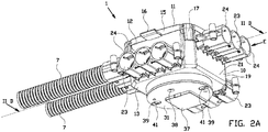
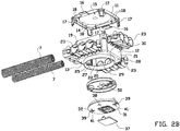
Figures 2A - 2D show an isometric view of the distribution box offigure 1A ; an exploded view of the distribution box having a top wall, a circumferential wall, a bottom wall, a lid and an airtight insert; an isometric view of the distribution box with the top wall, the lid and the airtight insert removed therefrom; and a cross-section of the distribution box offigure 2A along line IID, respectively; and -
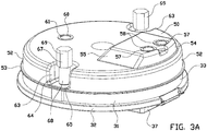
Figures 3A - 3C show an isometric view of the lid and the airtight insert; an exploded view of the lid and the airtight insert; and a cross-sectional view of the lid and the airtight insert, respectively. - An embodiment of a
distribution box 1 is shown infigures 1A and1B . Thedistribution box 1 is arranged at aceiling plate 2, such as plasterboard, having afront side 3 and aback side 4 opposite to thefront side 3. Thedistribution box 1 is secured to theback side 4 of theceiling plate 2 by means of twotransversal beams 5 and twolongitudinal beams 6 between which thedistribution box 1 is placed. A throughhole 8 is provided within theceiling plate 2, through which thedistribution box 1 partially extends and via which thedistribution box 1 is accessible.Flexible tubes 7 are connected to the distribution box, via which non-shown electric installation material including electric wirings is guided towards and into thedistribution box 1. - An isometric view of the
distribution box 1 is shown infigure 2A . Thedistribution box 1 comprises ahousing 10 having atop wall 11, acircumferential wall 12 upright from thetop wall 11, and abottom wall 13 opposite to thetop wall 11. Thetop wall 11, thecircumferential wall 12 and thebottom wall 13 together enclose an installation space for electric installation material. Thetop wall 11 is removable arranged at thecircumferential wall 12, thereby forming a removabletop lid 11. The removabletop wall 11 comprises atop body 14 which is substantially quadrangular. Thetop body 11 has an outer circumference, at which an enclosingedge 15 upright from thetop body 14 towards the circumferential wall is provided. Abutment flaps 16 are provided at opposite sides of the enclosingedge 15 for abutting to thelongitudinal beams 6 when installed at aceiling plate 2. A first engagingprotrusion 17 is provided at each of the corners of the quadrangulartop body 14, which first engagingprotrusions 17 are arranged for engaging thecircumferential wall 12 at the outside thereof. A pair of secondengaging protrusions 18 is provided in proximity of each of the first engagingprotrusions 17, wherein each pair of secondengaging protrusions 18 is arranged for engaging thecircumferential wall 12 at the inside thereof. When thetop body 14 is placed at thecircumferential wall 12, thecircumferential wall 12 is received between each first engagingprotrusion 17 and the associated pair of second engagingprotrusions 18. - The
circumferential wall 12 has awall body 19 withwire openings 20 therein via which electric cables or wires can be inserted into the installation space. Thewall body 19 has anouter side 21 and aninner side 22 opposite to theouter side 21. Multiple spouts 23 are arranged at theouter side 21 of thewall body 19, wherein eachspout 23 has multiple, in this case three,spout channels 24 extending through therespective spout 23 in an insert direction E substantially perpendicular to thewall body 19 and parallel to thebottom wall 11. Eachspout channel 24 is associated with and placed in line with one of thewire openings 20, such that non-shown electric cables or wires can be inserted into the installation space in the insert direction E via thespout channels 24 and the associatedcable opening 20. - As shown in
figures 2B and2C , two receivingbusses 25 are provided within the installation space. A first one of the two receivingbusses 25 is arranged at a first surface of theinner side 22 of thecircumferential wall 12 and the second one of the two receivingbusses 25 is arranged at a second surface, opposite to the first side, of theinner side 22 of thecircumferential wall 12. Each of the two receivingbusses 25 is secured to the respective surface of theinner side 22 by securingmembers 26 which are extending at an angle with respect to the respective surface of thecircumferential wall 12. The receiving busses 25 are each provided with a receivingopening 27 via which a receiving channel of the respective receiving buss is accessible. - As best shown in
figures 2A and2B , thebottom wall 13 has abottom body 28 with aninstallation opening 29 via which the installation space inside thedistribution box 1 is accessible. In an installed state of theinstallation box 1, theinstallation opening 29 can be used to access the installation space from the side of theceiling plate 2 directed towards, for example, a room. Theinstallation opening 29 is delimited by aninstallation edge 30 standing upright from thetop body 28 in a direction away from the installation space. - Furthermore, a
lid 31 is provided for being installed at theinstallation opening 29 to close off theinstallation opening 29 partially. Thelid 31 comprises alid body 32 with alid edge 33 standing upright from thelid body 32 in the direction towards the installation space of thedistribution box 1. Thelid 31 is provided with aterminal block chamber 34 for receiving aterminal block 43, wherein theterminal block chamber 34 is formed by a deepening in thelid body 33. Theterminal block chamber 34 has a chamber bottom 35 provided with twowiring openings 36 for electric wirings from the electric installation material to pass there through such that the electric wirings can be connected to theterminal block 43 within theterminal block chamber 34. Anadditional lid 37 is provided for closing off theterminal block chamber 34 at the side opposite to thechamber bottom 35. Theadditional lid 37 is removable from thelid 31 in order to access theterminal block 43 provided within theterminal block chamber 34. As best shown infigure 2A , thelid 31 comprises an additional wire opening 38 spaced from theadditional lid 37, through whichadditional wire opening 38 electric wiring can pass from and to the installation space. - As shown in
figures 2A and3B , thelid 31 has twoscrew recesses 39 with a through-hole through which ascrew 40 is able to pass while thescrew head 41 can be received within one of the screw recesses 39. When thescrews 40 are arranged within the screw recesses 39 of thelid 31, the receiving busses 25 are enabled to receive thescrews 40 in order to secure thelid 31 to thedistribution box 1. Thelid 31 further includes ahook hanging channel 42 with a hook hanging portion configured for hanging a non-shown hook at the hangingportion 44, for example, for hanging a lamp at thedistribution box 1 when installed at theceiling plate 2. - As best shown in
figure 2B , thedistribution box 1 is provided with anairtight insert 50 on top of thelid 31. Fromfigure 2D , it is clear that theairtight insert 50 is configured for being placed at theinstallation opening 29 of thedistribution box 1 and for being received by theinstallation edge 30. - As shown in
figures 3A and3B , theairtight insert 50 has a substantiallyflat insert body 51. At the outer circumference of theflat insert body 51, aninsert edge 52 standing upright from theinsert body 51 and extending towards thelid 31 is provided. The rim of theinsert edge 52 facing away from theinsert body 51 is adapted to be placed in abutting contact with the rim of thelid edge 33 facing away from thelid body 32. An engagingedge 53 is provided at the rim of theinsert edge 52, wherein the engagingedge 53 extends substantially radially outwards with respect to theinsert edge 52 in a plane parallel to theinsert body 51. As shown infigure 2D , when theairtight insert 50 is positioned within theinstallation opening 29, the engagingedge 53 is in engagement with the inner circumference of theinstallation edge 30 such that theinstallation opening 29 is closed off. At least the engagingedge 53 is made of a flexible material in order to provide a sealing engagement of the engagingedge 53 to the inner circumference of theinstallation edge 30. - As shown in
figures 3A and3B , theinsert body 51 of theairtight insert 50 is provided with aninsert receiving chamber 54. Theinsert receiving chamber 54 is positioned such that when theairtight insert 50 is arranged at thelid 31, theinsert receiving chamber 54 receives a part of theterminal block chamber 34 of thelid 31. Theinsert receiving chamber 54 has fourside walls 55 and abottom wall 56 that together define a receiving space for receiving a part of theterminal block chamber 34 of thelid 31. The top side of theinsert receiving chamber 54, i.e. the side opposite to thebottom wall 56, is open. Thebottom wall 56 of theinsert receiving chamber 54 is provided with twotarget fractures 57. Each of the twotarget fractures 57 is arranged such that it is positioned substantially straight above a corresponding one of thewiring openings 36. Each of thetarget fractures 57 comprises amembrane 58 which can be punctured by a non-shown electric wire, such that the electric wire can be inserted into theterminal block chamber 34 and can be connected to theterminal block 43. When the electric wire punctures themembrane 58 of one of thetarget fractures 57, themembrane 58 will abut the non-shown electric wire in a clamping manner over a few millimeters or less in length, like a cuff, such that an airtight seal is provided. An engagingindentation 59 is provided at theinsert receiving chamber 54, which engagingindentation 59 is provided partially in one of theside walls 55 and partially within thebottom wall 56. - It is noted that the engaging
indentation 58 can be required when theairtight insert 50 is used in combination with a non-shown height adjustment ring, when two non-shown thicker ceiling plates are used instead of one ceiling plate. - As shown in
figure 3A , theinsert body 51 has anadditional target fracture 60 with amembrane 61 to be punctured by a non-shown electric wire, such as the earth wire. Theadditional target fracture 60 is arranged such that it is positioned substantially straight above theadditional wire opening 38. - As shown in
figures 3A and3B , theairtight insert 50 is provided with two securingchannels 63 formed by a radially inwards securingindentation 64 provided in theinsert edge 52 of theinsert body 51. Each securingindentation 64 is provided with an indentation bottom 65, which is located at the rim of theinsert edge 52 facing away from theinsert body 51. Each of theindentation bottoms 65 has ascrew opening 66 for receiving acorresponding screw 40 when inserted into thelid 31. - Furthermore, two fixing
bushes 67 are provided, each having atubular portion 68 and apolygonal portion 69. Each of the two fixingbushes 67 is configured for receiving one of thescrews 40 extending through theairtight insert 50, as indicated infigure 3A . Each of thescrews 40 is thus received within the corresponding fixingbush 67, in particular thetubular portion 68 thereof. - Each of the two fixing
bushes 67 is fixated into one of the receiving busses 25 by placing the respective fixingbush 67 into a mould for producing thedistribution box 1 and, for example, injecting the material of thedistribution box 1 around the respective fixingbush 67. By thescrews 40 being received partially within the fixingbushes 67, theairtight insert 50 is secured to thelid 31, wherein thelid 31 with theairtight insert 50 can be secured to thedistribution box 1 by inserting thescrews 40 into the fixingbushes 67 within the receiving busses 25 arranged at thecircumferential wall 12. Theinstallation opening 29 of thedistribution box 1 is than closed off airtight. - It is to be understood that the above description is included to illustrate the operation of the preferred embodiments and is not meant to limit the scope of the invention. From the above discussion, many variations will be apparent to one skilled in the art that would yet be encompassed by the scope of the present invention.
-
- 1.
- distribution box
- 2.
- ceiling plate
- 3.
- front side
- 4.
- back side
- 5.
- transversal beams
- 6.
- longitudinal beams
- 7.
- Flexible tubes
- 8.
- through hole
- 10.
- housing
- 11.
- top wall
- 12.
- circumferential wall
- 13.
- bottom wall
- 14.
- top body
- 15.
- enclosing edge
- 16.
- abutment flaps
- 17.
- engaging protrusions
- 19.
- wall body
- 20.
- cable openings
- 21.
- outer side
- 22.
- inner side
- 23.
- spouts
- 24.
- spout channels
- 25.
- receiving busses
- 26.
- securing members
- 27.
- receiving opening
- 28.
- bottom body
- 29.
- installation opening
- 30.
- installation edge
- 31.
- lid
- 32.
- lid body
- 33.
- lid edge
- 34.
- terminal block chamber
- 35.
- chamber bottom
- 36.
- wiring openings
- 37.
- additional lid
- 38.
- additional wire opening
- 39.
- screw recesses
- 40.
- screws
- 41.
- screw heads
- 42.
- hook hanging channel
- 43.
- terminal block
- 44.
- hook hanging portion
- 50.
- airtight insert
- 51.
- insert body
- 52.
- insert edge
- 53.
- engaging edge
- 54.
- insert receiving chamber
- 55.
- side wall
- 56.
- bottom wall
- 57.
- target fracture
- 58.
- membrane
- 59.
- engaging indentation
- 60.
- additional target fracture
- 61.
- membrane
- 62.
- pressing indicator
- 63.
- securing channel
- 64.
- securing indentation
- 65.
- indentation bottom
- 66.
- screw opening
- 67.
- fixing bush
- 68.
- tubular portion
- 69.
- polygonal portion
Claims (15)
- Assembly of a distribution box (1) and electric installation material with electric wirings, wherein the distribution box (1) comprises a top wall (11) and a circumferential wall (12) upright from the top wall (11), wherein the top wall (11) and the circumferential wall (12) together enclose an installation space for installation material, wherein the distribution box (1) comprises a bottom plane, opposite to the top wall, in which an installation opening (29) is provided, wherein the circumferential wall (12) is provided with one or more wire openings (20) for electric wirings to pass through the circumferential wall (12), characterized in that a separate airtight insert (50) is provided, wherein the separate airtight insert (50) is configured to be mounted in or at the installation opening (29) for substantially closing off the installation opening air tight.
- Assembly according to claim 1, wherein the distribution box (1) comprises a bottom wall (13), opposite to the top wall (11), having the installation opening (29) provided therein, wherein the airtight insert (50) is configured to be received within the installation opening (29) .
- Assembly according to claim 2, wherein the bottom wall (13) comprises a bottom body (28) and an installation edge (30) standing upright from the bottom wall (28), preferably in a direction away from the installation space, wherein the installation opening (29) is delimited by the installation edge (30).
- Assembly according to any one of the preceding claims, wherein the airtight insert (50) comprises an insert body (51), preferably wherein the airtight insert is made of a soft material, such as plastic, or in a 2K plastic with a soft and hard plastic combined.
- Assembly according to claim 3 and claim 4, wherein the insert body (51) comprises an insert edge (52) standing upright from the insert body (51), and an engaging edge (53) provided at the rim of the insert edge (52) facing away from the insert body (51), wherein the engaging edge (53) extends substantially radially outwards with respect to the insert edge (52) in a plane parallel to the insert body (51), wherein the engaging edge (53) is configured to be in engagement with the inner circumference of the installation edge (30) when the airtight insert (50) is received within the installation opening (29).
- Assembly according to claim 4 or claim 5, wherein the insert body (51) has one or more passages for electric wirings to pass through the insert body (51), preferably wherein the one or more passages are target fractures (57), each of the one or more target fractures (57) comprising a membrane (58) to be penetrated by electric wirings to pass through the airtight insert (50).
- Assembly according to any one of the preceding claims, wherein the distribution box (1) comprises a lid (31) configured to be arranged within or at the installation opening (29), wherein the airtight insert (50) is configured to be placed between the lid and the installation space, preferably wherein the lid (31) has a lid body (32) with one or more wiring openings (36) for electric wirings to pass through the lid body (32).
- Assembly according to claim 6 and claim 7, wherein the one or more passages of the insert body (51) are arranged such that they are located in proximity of a corresponding one of the one or more wiring openings (36) of the lid body (32), preferably wherein the one or more passages are arranged substantially straight above the corresponding one of the one or more wiring openings (36).
- Assembly according to any one of the claims 7 or 8, wherein the lid (31) comprises a terminal block chamber (34) configured for receiving a terminal block (43), wherein the terminal block chamber (34) extends in a direction towards the airtight insert (50), and wherein the airtight insert (50) has an insert receiving chamber (54) configured for receiving the terminal block chamber (34) of the lid (31) at least partially, preferably wherein the insert receiving chamber (54) has an engaging indentation (54), preferably wherein the insert receiving chamber (54) has four side walls (55) and a bottom wall (56) that together define a receiving space for receiving the terminal block chamber (34) of the lid (31) at least partially, wherein the engaging indentation (59) is provided partially in one of the side walls (55) and partially within the bottom wall (56).
- Assembly according to any one of the claims 7 - 9, wherein the lid body (32) comprises one or more through-holes through which a screw (40) is able to pass, preferably wherein the lid body (32) has one or more screw recesses (39) with the one or more through-holes arranged therein, wherein a screw head (41) can be received within the one or more screw recesses (39).
- Assembly according to claim 10, when dependent on claim 4, wherein the insert body (51) comprises one or more securing channels (63) each formed by a radially inwards securing indentation (64) provided in the insert edge (52) of the insert body (51), wherein each of the one or more securing indentations (64) has an indentation bottom (65) with a screw opening (66) for allowing a screw (40) to pass there through when inserted into the lid (31), preferably wherein the assembly further comprises one or more fixing bushes (67) configured for receiving the screw (s) and for being received within the one or more securing channels (63), thereby clamping the airtight insert (50) between the lid (31) and the one or more fixing bushes (67), wherein the distribution box (1) comprises one or more receiving busses (25) with a receiving opening (27) and a receiving channel, wherein the one or more receiving busses (25) are arranged at the inner side (22) of the distribution box (1) and arranged for receiving the one or more fixing bushes (67) to secure the lid (31) and the airtight insert (50) to the distribution box (1) .
- Assembly according to claim 11, wherein each of the one or more fixing bushes (67) has a first portion (68) and a second portion (69), preferably different from the first portion, preferably wherein the first portion is a tubular portion (68) and the second portion is a polygonal portion (69), wherein the receiving channel of each of the one or more receiving busses (25) comprises a tubular portion for receiving the tubular portion (68) of one of the one or more fixing bushes (67), and a polygonal portion (69) for receiving the polygonal portion of the one of the one or more fixing bushes (67), or wherein each of the one or more fixing bushes (67) comprises a nut.
- Airtight insert and/or distribution box for use in an assembly according to any one of the preceding claims.
- Method for mounting a separate airtight insert (50) in a distribution box of an assembly of a distribution box (1) and electric installation material with electric wirings, in particular according to any one of the claims 1 to 12, the method comprising the steps of:- installing a distribution box (2) at a hollow wall, such as a hollow ceiling (2);- inserting electric installation material with electric wirings into the distribution box (1);- making electric connections between electric wirings of the electric installation material; and- mounting the separate airtight insert (50) in or at the installation opening (29) of the distribution box (1), such that the installation opening is closed off substantially airtight.
- Method according to claim 14, wherein the distribution box (1) comprises a lid (31) configured to be arranged within or at the installation opening (29), the method further comprising the step of:- arranging the airtight insert (50) at the lid (31), preferably at a side of the lid (31) facing the installation space of the distribution box (1).
Priority Applications (4)
| Application Number | Priority Date | Filing Date | Title |
|---|---|---|---|
| EP19162509.4A EP3709462B1 (en) | 2019-03-13 | 2019-03-13 | Assembly of a distribution box and electric installation material, and airtight insert |
| FIEP19162509.4T FI3709462T3 (en) | 2019-03-13 | 2019-03-13 | Assembly of a distribution box and electric installation material, and airtight insert |
| DK19162509.4T DK3709462T3 (en) | 2019-03-13 | 2019-03-13 | Assembly of a junction box and electrical installation material, and airtight insert |
| EP19170028.5A EP3709460B1 (en) | 2019-03-13 | 2019-04-18 | Spout, and an assembly of a distribution box and electric installation material |
Applications Claiming Priority (1)
| Application Number | Priority Date | Filing Date | Title |
|---|---|---|---|
| EP19162509.4A EP3709462B1 (en) | 2019-03-13 | 2019-03-13 | Assembly of a distribution box and electric installation material, and airtight insert |
Publications (2)
| Publication Number | Publication Date |
|---|---|
| EP3709462A1 true EP3709462A1 (en) | 2020-09-16 |
| EP3709462B1 EP3709462B1 (en) | 2023-12-27 |
Family
ID=65903892
Family Applications (2)
| Application Number | Title | Priority Date | Filing Date |
|---|---|---|---|
| EP19162509.4A Active EP3709462B1 (en) | 2019-03-13 | 2019-03-13 | Assembly of a distribution box and electric installation material, and airtight insert |
| EP19170028.5A Active EP3709460B1 (en) | 2019-03-13 | 2019-04-18 | Spout, and an assembly of a distribution box and electric installation material |
Family Applications After (1)
| Application Number | Title | Priority Date | Filing Date |
|---|---|---|---|
| EP19170028.5A Active EP3709460B1 (en) | 2019-03-13 | 2019-04-18 | Spout, and an assembly of a distribution box and electric installation material |
Country Status (3)
| Country | Link |
|---|---|
| EP (2) | EP3709462B1 (en) |
| DK (1) | DK3709462T3 (en) |
| FI (1) | FI3709462T3 (en) |
Citations (3)
| Publication number | Priority date | Publication date | Assignee | Title |
|---|---|---|---|---|
| JPH07274346A (en) * | 1994-03-29 | 1995-10-20 | Mirai Ind Co Ltd | Dustproof packing for boxes |
| US20090255703A1 (en) * | 2008-04-11 | 2009-10-15 | Hubbell Incorporated | Lift cover and gasket assembly |
| US20120222880A1 (en) * | 2011-03-04 | 2012-09-06 | Thomas & Betts International, Inc. | Water-resistant while-in-use electrical box |
Family Cites Families (4)
| Publication number | Priority date | Publication date | Assignee | Title |
|---|---|---|---|---|
| US5789706A (en) * | 1997-01-17 | 1998-08-04 | Perkins; Vernon | Electrical cable to utilization device quick connector |
| BE1014554A3 (en) * | 2001-12-21 | 2003-12-02 | Jvk Plastics Nv | Installation box for electrical components. |
| CH708567B1 (en) * | 2013-08-29 | 2021-01-29 | Morach Christoph | Device for electrical installations. |
| CH713013B1 (en) * | 2016-10-06 | 2021-07-15 | Morach Christoph | Device for electrical installations, having at least one latching element and at least one connection channel for inserting an installation pipe. |
-
2019
- 2019-03-13 FI FIEP19162509.4T patent/FI3709462T3/en active
- 2019-03-13 DK DK19162509.4T patent/DK3709462T3/en active
- 2019-03-13 EP EP19162509.4A patent/EP3709462B1/en active Active
- 2019-04-18 EP EP19170028.5A patent/EP3709460B1/en active Active
Patent Citations (3)
| Publication number | Priority date | Publication date | Assignee | Title |
|---|---|---|---|---|
| JPH07274346A (en) * | 1994-03-29 | 1995-10-20 | Mirai Ind Co Ltd | Dustproof packing for boxes |
| US20090255703A1 (en) * | 2008-04-11 | 2009-10-15 | Hubbell Incorporated | Lift cover and gasket assembly |
| US20120222880A1 (en) * | 2011-03-04 | 2012-09-06 | Thomas & Betts International, Inc. | Water-resistant while-in-use electrical box |
Also Published As
| Publication number | Publication date |
|---|---|
| EP3709460B1 (en) | 2026-07-15 |
| EP3709460A1 (en) | 2020-09-16 |
| FI3709462T3 (en) | 2024-01-08 |
| EP3709462B1 (en) | 2023-12-27 |
| DK3709462T3 (en) | 2024-03-18 |
Similar Documents
| Publication | Publication Date | Title |
|---|---|---|
| US12209736B2 (en) | Polymer housing for a lighting system and methods for using same | |
| US7307212B1 (en) | Electrical box assembly with internal mounting arrangement and flange to seal against air infiltration | |
| CN109565166B (en) | Cable Pass-Throughs and Kits | |
| CA2545799C (en) | Electrical ceiling box for fixture support | |
| US7227085B1 (en) | Reconfigurable conduit body assembly | |
| US9689578B2 (en) | Refrigerant distribution unit for air conditioner | |
| US20100025066A1 (en) | Two-gang mud ring universal base | |
| US20120262833A1 (en) | Motor control apparatus and bush therefor | |
| BRPI1102953A2 (en) | refrigerant distribution unit for air conditioner | |
| US7307214B1 (en) | Electrical fixture mounting assembly with sealing flange | |
| EP3709462B1 (en) | Assembly of a distribution box and electric installation material, and airtight insert | |
| GB2190253A (en) | Terminating heater cables sealed junction box | |
| CA2743286C (en) | Cable entry device for wiring boxes | |
| KR100980310B1 (en) | Fixing bracket for cable and the method | |
| KR100902134B1 (en) | Gasket for connecting the duct of the connecting duct | |
| US6322083B1 (en) | Insulating gasket | |
| CN102725577A (en) | Adapter for fastening a profiled support element | |
| US11303105B2 (en) | Insulating box and method for electrical outlets, switches and light fixtures | |
| EP0705982B1 (en) | Fan | |
| CN217636348U (en) | a refrigerator | |
| HU219248B (en) | Assembly molder half-covered box via cable-tunnel and method for mounting it | |
| CN223537909U (en) | Refrigerator door structure and refrigerator | |
| JPH034111Y2 (en) | ||
| EP1801944B1 (en) | Electrical box with ring | |
| GB2094071A (en) | Improvements in or relating to electrical conduit boxes |
Legal Events
| Date | Code | Title | Description |
|---|---|---|---|
| PUAI | Public reference made under article 153(3) epc to a published international application that has entered the european phase |
Free format text: ORIGINAL CODE: 0009012 |
|
| STAA | Information on the status of an ep patent application or granted ep patent |
Free format text: STATUS: THE APPLICATION HAS BEEN PUBLISHED |
|
| AK | Designated contracting states |
Kind code of ref document: A1 Designated state(s): AL AT BE BG CH CY CZ DE DK EE ES FI FR GB GR HR HU IE IS IT LI LT LU LV MC MK MT NL NO PL PT RO RS SE SI SK SM TR |
|
| AX | Request for extension of the european patent |
Extension state: BA ME |
|
| STAA | Information on the status of an ep patent application or granted ep patent |
Free format text: STATUS: REQUEST FOR EXAMINATION WAS MADE |
|
| 17P | Request for examination filed |
Effective date: 20210316 |
|
| RAP3 | Party data changed (applicant data changed or rights of an application transferred) |
Owner name: ABB SCHWEIZ AG |
|
| STAA | Information on the status of an ep patent application or granted ep patent |
Free format text: STATUS: EXAMINATION IS IN PROGRESS |
|
| 17Q | First examination report despatched |
Effective date: 20210728 |
|
| GRAP | Despatch of communication of intention to grant a patent |
Free format text: ORIGINAL CODE: EPIDOSNIGR1 |
|
| STAA | Information on the status of an ep patent application or granted ep patent |
Free format text: STATUS: GRANT OF PATENT IS INTENDED |
|
| RIC1 | Information provided on ipc code assigned before grant |
Ipc: H02G 3/12 20060101ALN20230214BHEP Ipc: H02G 3/06 20060101ALN20230214BHEP Ipc: F16L 25/14 20060101ALN20230214BHEP Ipc: F16L 25/00 20060101ALN20230214BHEP Ipc: H02G 3/14 20060101ALN20230214BHEP Ipc: H02G 3/20 20060101ALI20230214BHEP Ipc: H02G 3/08 20060101AFI20230214BHEP |
|
| INTG | Intention to grant announced |
Effective date: 20230302 |
|
| GRAJ | Information related to disapproval of communication of intention to grant by the applicant or resumption of examination proceedings by the epo deleted |
Free format text: ORIGINAL CODE: EPIDOSDIGR1 |
|
| STAA | Information on the status of an ep patent application or granted ep patent |
Free format text: STATUS: EXAMINATION IS IN PROGRESS |
|
| GRAS | Grant fee paid |
Free format text: ORIGINAL CODE: EPIDOSNIGR3 |
|
| STAA | Information on the status of an ep patent application or granted ep patent |
Free format text: STATUS: GRANT OF PATENT IS INTENDED |
|
| GRAP | Despatch of communication of intention to grant a patent |
Free format text: ORIGINAL CODE: EPIDOSNIGR1 |
|
| INTC | Intention to grant announced (deleted) | ||
| RIC1 | Information provided on ipc code assigned before grant |
Ipc: H02G 3/12 20060101ALN20230706BHEP Ipc: H02G 3/06 20060101ALN20230706BHEP Ipc: F16L 25/14 20060101ALN20230706BHEP Ipc: F16L 25/00 20060101ALN20230706BHEP Ipc: H02G 3/14 20060101ALN20230706BHEP Ipc: H02G 3/20 20060101ALI20230706BHEP Ipc: H02G 3/08 20060101AFI20230706BHEP |
|
| INTG | Intention to grant announced |
Effective date: 20230718 |
|
| GRAA | (expected) grant |
Free format text: ORIGINAL CODE: 0009210 |
|
| STAA | Information on the status of an ep patent application or granted ep patent |
Free format text: STATUS: THE PATENT HAS BEEN GRANTED |
|
| AK | Designated contracting states |
Kind code of ref document: B1 Designated state(s): AL AT BE BG CH CY CZ DE DK EE ES FI FR GB GR HR HU IE IS IT LI LT LU LV MC MK MT NL NO PL PT RO RS SE SI SK SM TR |
|
| REG | Reference to a national code |
Ref country code: GB Ref legal event code: FG4D |
|
| REG | Reference to a national code |
Ref country code: CH Ref legal event code: EP |
|
| REG | Reference to a national code |
Ref country code: DE Ref legal event code: R096 Ref document number: 602019043847 Country of ref document: DE |
|
| REG | Reference to a national code |
Ref country code: FI Ref legal event code: FGE |
|
| REG | Reference to a national code |
Ref country code: IE Ref legal event code: FG4D |
|
| REG | Reference to a national code |
Ref country code: SE Ref legal event code: TRGR |
|
| REG | Reference to a national code |
Ref country code: DK Ref legal event code: T3 Effective date: 20240313 |
|
| PG25 | Lapsed in a contracting state [announced via postgrant information from national office to epo] |
Ref country code: GR Free format text: LAPSE BECAUSE OF FAILURE TO SUBMIT A TRANSLATION OF THE DESCRIPTION OR TO PAY THE FEE WITHIN THE PRESCRIBED TIME-LIMIT Effective date: 20240328 |
|
| REG | Reference to a national code |
Ref country code: NL Ref legal event code: FP Ref country code: LT Ref legal event code: MG9D |
|
| PG25 | Lapsed in a contracting state [announced via postgrant information from national office to epo] |
Ref country code: LT Free format text: LAPSE BECAUSE OF FAILURE TO SUBMIT A TRANSLATION OF THE DESCRIPTION OR TO PAY THE FEE WITHIN THE PRESCRIBED TIME-LIMIT Effective date: 20231227 |
|
| PG25 | Lapsed in a contracting state [announced via postgrant information from national office to epo] |
Ref country code: ES Free format text: LAPSE BECAUSE OF FAILURE TO SUBMIT A TRANSLATION OF THE DESCRIPTION OR TO PAY THE FEE WITHIN THE PRESCRIBED TIME-LIMIT Effective date: 20231227 |
|
| PG25 | Lapsed in a contracting state [announced via postgrant information from national office to epo] |
Ref country code: LT Free format text: LAPSE BECAUSE OF FAILURE TO SUBMIT A TRANSLATION OF THE DESCRIPTION OR TO PAY THE FEE WITHIN THE PRESCRIBED TIME-LIMIT Effective date: 20231227 Ref country code: GR Free format text: LAPSE BECAUSE OF FAILURE TO SUBMIT A TRANSLATION OF THE DESCRIPTION OR TO PAY THE FEE WITHIN THE PRESCRIBED TIME-LIMIT Effective date: 20240328 Ref country code: ES Free format text: LAPSE BECAUSE OF FAILURE TO SUBMIT A TRANSLATION OF THE DESCRIPTION OR TO PAY THE FEE WITHIN THE PRESCRIBED TIME-LIMIT Effective date: 20231227 Ref country code: BG Free format text: LAPSE BECAUSE OF FAILURE TO SUBMIT A TRANSLATION OF THE DESCRIPTION OR TO PAY THE FEE WITHIN THE PRESCRIBED TIME-LIMIT Effective date: 20240327 |
|
| REG | Reference to a national code |
Ref country code: AT Ref legal event code: MK05 Ref document number: 1645436 Country of ref document: AT Kind code of ref document: T Effective date: 20231227 |
|
| PG25 | Lapsed in a contracting state [announced via postgrant information from national office to epo] |
Ref country code: RS Free format text: LAPSE BECAUSE OF FAILURE TO SUBMIT A TRANSLATION OF THE DESCRIPTION OR TO PAY THE FEE WITHIN THE PRESCRIBED TIME-LIMIT Effective date: 20231227 Ref country code: NO Free format text: LAPSE BECAUSE OF FAILURE TO SUBMIT A TRANSLATION OF THE DESCRIPTION OR TO PAY THE FEE WITHIN THE PRESCRIBED TIME-LIMIT Effective date: 20240327 Ref country code: LV Free format text: LAPSE BECAUSE OF FAILURE TO SUBMIT A TRANSLATION OF THE DESCRIPTION OR TO PAY THE FEE WITHIN THE PRESCRIBED TIME-LIMIT Effective date: 20231227 Ref country code: HR Free format text: LAPSE BECAUSE OF FAILURE TO SUBMIT A TRANSLATION OF THE DESCRIPTION OR TO PAY THE FEE WITHIN THE PRESCRIBED TIME-LIMIT Effective date: 20231227 |
|
| PG25 | Lapsed in a contracting state [announced via postgrant information from national office to epo] |
Ref country code: IS Free format text: LAPSE BECAUSE OF FAILURE TO SUBMIT A TRANSLATION OF THE DESCRIPTION OR TO PAY THE FEE WITHIN THE PRESCRIBED TIME-LIMIT Effective date: 20240427 |
|
| PG25 | Lapsed in a contracting state [announced via postgrant information from national office to epo] |
Ref country code: CZ Free format text: LAPSE BECAUSE OF FAILURE TO SUBMIT A TRANSLATION OF THE DESCRIPTION OR TO PAY THE FEE WITHIN THE PRESCRIBED TIME-LIMIT Effective date: 20231227 Ref country code: AT Free format text: LAPSE BECAUSE OF FAILURE TO SUBMIT A TRANSLATION OF THE DESCRIPTION OR TO PAY THE FEE WITHIN THE PRESCRIBED TIME-LIMIT Effective date: 20231227 |
|
| PG25 | Lapsed in a contracting state [announced via postgrant information from national office to epo] |
Ref country code: SK Free format text: LAPSE BECAUSE OF FAILURE TO SUBMIT A TRANSLATION OF THE DESCRIPTION OR TO PAY THE FEE WITHIN THE PRESCRIBED TIME-LIMIT Effective date: 20231227 |
|
| PG25 | Lapsed in a contracting state [announced via postgrant information from national office to epo] |
Ref country code: SM Free format text: LAPSE BECAUSE OF FAILURE TO SUBMIT A TRANSLATION OF THE DESCRIPTION OR TO PAY THE FEE WITHIN THE PRESCRIBED TIME-LIMIT Effective date: 20231227 Ref country code: SK Free format text: LAPSE BECAUSE OF FAILURE TO SUBMIT A TRANSLATION OF THE DESCRIPTION OR TO PAY THE FEE WITHIN THE PRESCRIBED TIME-LIMIT Effective date: 20231227 Ref country code: RO Free format text: LAPSE BECAUSE OF FAILURE TO SUBMIT A TRANSLATION OF THE DESCRIPTION OR TO PAY THE FEE WITHIN THE PRESCRIBED TIME-LIMIT Effective date: 20231227 Ref country code: IT Free format text: LAPSE BECAUSE OF FAILURE TO SUBMIT A TRANSLATION OF THE DESCRIPTION OR TO PAY THE FEE WITHIN THE PRESCRIBED TIME-LIMIT Effective date: 20231227 Ref country code: IS Free format text: LAPSE BECAUSE OF FAILURE TO SUBMIT A TRANSLATION OF THE DESCRIPTION OR TO PAY THE FEE WITHIN THE PRESCRIBED TIME-LIMIT Effective date: 20240427 Ref country code: EE Free format text: LAPSE BECAUSE OF FAILURE TO SUBMIT A TRANSLATION OF THE DESCRIPTION OR TO PAY THE FEE WITHIN THE PRESCRIBED TIME-LIMIT Effective date: 20231227 Ref country code: CZ Free format text: LAPSE BECAUSE OF FAILURE TO SUBMIT A TRANSLATION OF THE DESCRIPTION OR TO PAY THE FEE WITHIN THE PRESCRIBED TIME-LIMIT Effective date: 20231227 Ref country code: AT Free format text: LAPSE BECAUSE OF FAILURE TO SUBMIT A TRANSLATION OF THE DESCRIPTION OR TO PAY THE FEE WITHIN THE PRESCRIBED TIME-LIMIT Effective date: 20231227 |
|
| PG25 | Lapsed in a contracting state [announced via postgrant information from national office to epo] |
Ref country code: PT Free format text: LAPSE BECAUSE OF FAILURE TO SUBMIT A TRANSLATION OF THE DESCRIPTION OR TO PAY THE FEE WITHIN THE PRESCRIBED TIME-LIMIT Effective date: 20240429 Ref country code: PL Free format text: LAPSE BECAUSE OF FAILURE TO SUBMIT A TRANSLATION OF THE DESCRIPTION OR TO PAY THE FEE WITHIN THE PRESCRIBED TIME-LIMIT Effective date: 20231227 |
|
| PG25 | Lapsed in a contracting state [announced via postgrant information from national office to epo] |
Ref country code: PT Free format text: LAPSE BECAUSE OF FAILURE TO SUBMIT A TRANSLATION OF THE DESCRIPTION OR TO PAY THE FEE WITHIN THE PRESCRIBED TIME-LIMIT Effective date: 20240429 Ref country code: PL Free format text: LAPSE BECAUSE OF FAILURE TO SUBMIT A TRANSLATION OF THE DESCRIPTION OR TO PAY THE FEE WITHIN THE PRESCRIBED TIME-LIMIT Effective date: 20231227 |
|
| REG | Reference to a national code |
Ref country code: DE Ref legal event code: R097 Ref document number: 602019043847 Country of ref document: DE |
|
| REG | Reference to a national code |
Ref country code: DE Ref legal event code: R119 Ref document number: 602019043847 Country of ref document: DE |
|
| REG | Reference to a national code |
Ref country code: CH Ref legal event code: PL |
|
| PLBE | No opposition filed within time limit |
Free format text: ORIGINAL CODE: 0009261 |
|
| STAA | Information on the status of an ep patent application or granted ep patent |
Free format text: STATUS: NO OPPOSITION FILED WITHIN TIME LIMIT |
|
| PG25 | Lapsed in a contracting state [announced via postgrant information from national office to epo] |
Ref country code: LU Free format text: LAPSE BECAUSE OF NON-PAYMENT OF DUE FEES Effective date: 20240313 |
|
| PG25 | Lapsed in a contracting state [announced via postgrant information from national office to epo] |
Ref country code: MC Free format text: LAPSE BECAUSE OF FAILURE TO SUBMIT A TRANSLATION OF THE DESCRIPTION OR TO PAY THE FEE WITHIN THE PRESCRIBED TIME-LIMIT Effective date: 20231227 |
|
| GBPC | Gb: european patent ceased through non-payment of renewal fee |
Effective date: 20240327 |
|
| PG25 | Lapsed in a contracting state [announced via postgrant information from national office to epo] |
Ref country code: MC Free format text: LAPSE BECAUSE OF FAILURE TO SUBMIT A TRANSLATION OF THE DESCRIPTION OR TO PAY THE FEE WITHIN THE PRESCRIBED TIME-LIMIT Effective date: 20231227 Ref country code: LU Free format text: LAPSE BECAUSE OF NON-PAYMENT OF DUE FEES Effective date: 20240313 |
|
| 26N | No opposition filed |
Effective date: 20240930 |
|
| REG | Reference to a national code |
Ref country code: BE Ref legal event code: MM Effective date: 20240331 |
|
| PG25 | Lapsed in a contracting state [announced via postgrant information from national office to epo] |
Ref country code: DE Free format text: LAPSE BECAUSE OF NON-PAYMENT OF DUE FEES Effective date: 20241001 |
|
| PG25 | Lapsed in a contracting state [announced via postgrant information from national office to epo] |
Ref country code: BE Free format text: LAPSE BECAUSE OF NON-PAYMENT OF DUE FEES Effective date: 20240331 |
|
| PG25 | Lapsed in a contracting state [announced via postgrant information from national office to epo] |
Ref country code: GB Free format text: LAPSE BECAUSE OF NON-PAYMENT OF DUE FEES Effective date: 20240327 |
|
| PG25 | Lapsed in a contracting state [announced via postgrant information from national office to epo] |
Ref country code: FR Free format text: LAPSE BECAUSE OF NON-PAYMENT OF DUE FEES Effective date: 20240331 |
|
| PG25 | Lapsed in a contracting state [announced via postgrant information from national office to epo] |
Ref country code: IE Free format text: LAPSE BECAUSE OF NON-PAYMENT OF DUE FEES Effective date: 20240313 |
|
| PG25 | Lapsed in a contracting state [announced via postgrant information from national office to epo] |
Ref country code: IE Free format text: LAPSE BECAUSE OF NON-PAYMENT OF DUE FEES Effective date: 20240313 Ref country code: GB Free format text: LAPSE BECAUSE OF NON-PAYMENT OF DUE FEES Effective date: 20240327 Ref country code: FR Free format text: LAPSE BECAUSE OF NON-PAYMENT OF DUE FEES Effective date: 20240331 Ref country code: DE Free format text: LAPSE BECAUSE OF NON-PAYMENT OF DUE FEES Effective date: 20241001 Ref country code: BE Free format text: LAPSE BECAUSE OF NON-PAYMENT OF DUE FEES Effective date: 20240331 Ref country code: CH Free format text: LAPSE BECAUSE OF NON-PAYMENT OF DUE FEES Effective date: 20240331 |
|
| PG25 | Lapsed in a contracting state [announced via postgrant information from national office to epo] |
Ref country code: SI Free format text: LAPSE BECAUSE OF FAILURE TO SUBMIT A TRANSLATION OF THE DESCRIPTION OR TO PAY THE FEE WITHIN THE PRESCRIBED TIME-LIMIT Effective date: 20231227 |
|
| PG25 | Lapsed in a contracting state [announced via postgrant information from national office to epo] |
Ref country code: CY Free format text: LAPSE BECAUSE OF FAILURE TO SUBMIT A TRANSLATION OF THE DESCRIPTION OR TO PAY THE FEE WITHIN THE PRESCRIBED TIME-LIMIT; INVALID AB INITIO Effective date: 20190313 |
|
| PG25 | Lapsed in a contracting state [announced via postgrant information from national office to epo] |
Ref country code: HU Free format text: LAPSE BECAUSE OF FAILURE TO SUBMIT A TRANSLATION OF THE DESCRIPTION OR TO PAY THE FEE WITHIN THE PRESCRIBED TIME-LIMIT; INVALID AB INITIO Effective date: 20190313 |
|
| PG25 | Lapsed in a contracting state [announced via postgrant information from national office to epo] |
Ref country code: TR Free format text: LAPSE BECAUSE OF FAILURE TO SUBMIT A TRANSLATION OF THE DESCRIPTION OR TO PAY THE FEE WITHIN THE PRESCRIBED TIME-LIMIT Effective date: 20231227 |
|
| PGFP | Annual fee paid to national office [announced via postgrant information from national office to epo] |
Ref country code: SE Payment date: 20260319 Year of fee payment: 8 |
|
| PGFP | Annual fee paid to national office [announced via postgrant information from national office to epo] |
Ref country code: DK Payment date: 20260324 Year of fee payment: 8 |
|
| PGFP | Annual fee paid to national office [announced via postgrant information from national office to epo] |
Ref country code: FI Payment date: 20260323 Year of fee payment: 8 |
|
| PGFP | Annual fee paid to national office [announced via postgrant information from national office to epo] |
Ref country code: NL Payment date: 20260319 Year of fee payment: 8 |