EP3709211A1 - Under-screen fingerprint recognition system, liquid crystal display screen fingerprint recognition apparatus and electronic device - Google Patents
Under-screen fingerprint recognition system, liquid crystal display screen fingerprint recognition apparatus and electronic device Download PDFInfo
- Publication number
- EP3709211A1 EP3709211A1 EP19821433.0A EP19821433A EP3709211A1 EP 3709211 A1 EP3709211 A1 EP 3709211A1 EP 19821433 A EP19821433 A EP 19821433A EP 3709211 A1 EP3709211 A1 EP 3709211A1
- Authority
- EP
- European Patent Office
- Prior art keywords
- liquid crystal
- fingerprint
- reflection
- reflection unit
- crystal panel
- Prior art date
- Legal status (The legal status is an assumption and is not a legal conclusion. Google has not performed a legal analysis and makes no representation as to the accuracy of the status listed.)
- Withdrawn
Links
Images

Classifications
-
- G—PHYSICS
- G06—COMPUTING OR CALCULATING; COUNTING
- G06V—IMAGE OR VIDEO RECOGNITION OR UNDERSTANDING
- G06V40/00—Recognition of biometric, human-related or animal-related patterns in image or video data
- G06V40/10—Human or animal bodies, e.g. vehicle occupants or pedestrians; Body parts, e.g. hands
- G06V40/12—Fingerprints or palmprints
- G06V40/13—Sensors therefor
- G06V40/1318—Sensors therefor using electro-optical elements or layers, e.g. electroluminescent sensing
-
- G—PHYSICS
- G02—OPTICS
- G02F—OPTICAL DEVICES OR ARRANGEMENTS FOR THE CONTROL OF LIGHT BY MODIFICATION OF THE OPTICAL PROPERTIES OF THE MEDIA OF THE ELEMENTS INVOLVED THEREIN; NON-LINEAR OPTICS; FREQUENCY-CHANGING OF LIGHT; OPTICAL LOGIC ELEMENTS; OPTICAL ANALOGUE/DIGITAL CONVERTERS
- G02F1/00—Devices or arrangements for the control of the intensity, colour, phase, polarisation or direction of light arriving from an independent light source, e.g. switching, gating or modulating; Non-linear optics
- G02F1/01—Devices or arrangements for the control of the intensity, colour, phase, polarisation or direction of light arriving from an independent light source, e.g. switching, gating or modulating; Non-linear optics for the control of the intensity, phase, polarisation or colour
- G02F1/13—Devices or arrangements for the control of the intensity, colour, phase, polarisation or direction of light arriving from an independent light source, e.g. switching, gating or modulating; Non-linear optics for the control of the intensity, phase, polarisation or colour based on liquid crystals, e.g. single liquid crystal display cells
- G02F1/133—Constructional arrangements; Operation of liquid crystal cells; Circuit arrangements
- G02F1/1333—Constructional arrangements; Manufacturing methods
- G02F1/13338—Input devices, e.g. touch panels
-
- G—PHYSICS
- G02—OPTICS
- G02B—OPTICAL ELEMENTS, SYSTEMS OR APPARATUS
- G02B6/00—Light guides; Structural details of arrangements comprising light guides and other optical elements, e.g. couplings
- G02B6/0001—Light guides; Structural details of arrangements comprising light guides and other optical elements, e.g. couplings specially adapted for lighting devices or systems
- G02B6/0011—Light guides; Structural details of arrangements comprising light guides and other optical elements, e.g. couplings specially adapted for lighting devices or systems the light guides being planar or of plate-like form
-
- G—PHYSICS
- G02—OPTICS
- G02F—OPTICAL DEVICES OR ARRANGEMENTS FOR THE CONTROL OF LIGHT BY MODIFICATION OF THE OPTICAL PROPERTIES OF THE MEDIA OF THE ELEMENTS INVOLVED THEREIN; NON-LINEAR OPTICS; FREQUENCY-CHANGING OF LIGHT; OPTICAL LOGIC ELEMENTS; OPTICAL ANALOGUE/DIGITAL CONVERTERS
- G02F1/00—Devices or arrangements for the control of the intensity, colour, phase, polarisation or direction of light arriving from an independent light source, e.g. switching, gating or modulating; Non-linear optics
- G02F1/01—Devices or arrangements for the control of the intensity, colour, phase, polarisation or direction of light arriving from an independent light source, e.g. switching, gating or modulating; Non-linear optics for the control of the intensity, phase, polarisation or colour
- G02F1/13—Devices or arrangements for the control of the intensity, colour, phase, polarisation or direction of light arriving from an independent light source, e.g. switching, gating or modulating; Non-linear optics for the control of the intensity, phase, polarisation or colour based on liquid crystals, e.g. single liquid crystal display cells
- G02F1/133—Constructional arrangements; Operation of liquid crystal cells; Circuit arrangements
- G02F1/13306—Circuit arrangements or driving methods for the control of single liquid crystal cells
- G02F1/13318—Circuits comprising a photodetector
-
- G—PHYSICS
- G02—OPTICS
- G02F—OPTICAL DEVICES OR ARRANGEMENTS FOR THE CONTROL OF LIGHT BY MODIFICATION OF THE OPTICAL PROPERTIES OF THE MEDIA OF THE ELEMENTS INVOLVED THEREIN; NON-LINEAR OPTICS; FREQUENCY-CHANGING OF LIGHT; OPTICAL LOGIC ELEMENTS; OPTICAL ANALOGUE/DIGITAL CONVERTERS
- G02F1/00—Devices or arrangements for the control of the intensity, colour, phase, polarisation or direction of light arriving from an independent light source, e.g. switching, gating or modulating; Non-linear optics
- G02F1/01—Devices or arrangements for the control of the intensity, colour, phase, polarisation or direction of light arriving from an independent light source, e.g. switching, gating or modulating; Non-linear optics for the control of the intensity, phase, polarisation or colour
- G02F1/13—Devices or arrangements for the control of the intensity, colour, phase, polarisation or direction of light arriving from an independent light source, e.g. switching, gating or modulating; Non-linear optics for the control of the intensity, phase, polarisation or colour based on liquid crystals, e.g. single liquid crystal display cells
- G02F1/133—Constructional arrangements; Operation of liquid crystal cells; Circuit arrangements
- G02F1/1333—Constructional arrangements; Manufacturing methods
- G02F1/133308—Support structures for LCD panels, e.g. frames or bezels
-
- G—PHYSICS
- G06—COMPUTING OR CALCULATING; COUNTING
- G06V—IMAGE OR VIDEO RECOGNITION OR UNDERSTANDING
- G06V40/00—Recognition of biometric, human-related or animal-related patterns in image or video data
- G06V40/10—Human or animal bodies, e.g. vehicle occupants or pedestrians; Body parts, e.g. hands
- G06V40/12—Fingerprints or palmprints
-
- G—PHYSICS
- G02—OPTICS
- G02F—OPTICAL DEVICES OR ARRANGEMENTS FOR THE CONTROL OF LIGHT BY MODIFICATION OF THE OPTICAL PROPERTIES OF THE MEDIA OF THE ELEMENTS INVOLVED THEREIN; NON-LINEAR OPTICS; FREQUENCY-CHANGING OF LIGHT; OPTICAL LOGIC ELEMENTS; OPTICAL ANALOGUE/DIGITAL CONVERTERS
- G02F1/00—Devices or arrangements for the control of the intensity, colour, phase, polarisation or direction of light arriving from an independent light source, e.g. switching, gating or modulating; Non-linear optics
- G02F1/01—Devices or arrangements for the control of the intensity, colour, phase, polarisation or direction of light arriving from an independent light source, e.g. switching, gating or modulating; Non-linear optics for the control of the intensity, phase, polarisation or colour
- G02F1/13—Devices or arrangements for the control of the intensity, colour, phase, polarisation or direction of light arriving from an independent light source, e.g. switching, gating or modulating; Non-linear optics for the control of the intensity, phase, polarisation or colour based on liquid crystals, e.g. single liquid crystal display cells
- G02F1/133—Constructional arrangements; Operation of liquid crystal cells; Circuit arrangements
- G02F1/1333—Constructional arrangements; Manufacturing methods
- G02F1/133308—Support structures for LCD panels, e.g. frames or bezels
- G02F1/133331—Cover glasses
-
- G—PHYSICS
- G06—COMPUTING OR CALCULATING; COUNTING
- G06V—IMAGE OR VIDEO RECOGNITION OR UNDERSTANDING
- G06V40/00—Recognition of biometric, human-related or animal-related patterns in image or video data
- G06V40/10—Human or animal bodies, e.g. vehicle occupants or pedestrians; Body parts, e.g. hands
- G06V40/12—Fingerprints or palmprints
- G06V40/1341—Sensing with light passing through the finger
Definitions
- Embodiments of the present application relate to the recognition technology, and in particular, to an under-screen fingerprint recognition system, a liquid crystal display fingerprint recognition apparatus, and an electronic device.
- the under-screen optical fingerprint solution of the OLED display screen detects a fingerprint by irradiating the finger using light of the screen itself and employing the light transmittance of the OLED display screen.
- the embodiments of the present application provide an under-screen fingerprint recognition system, a liquid crystal display fingerprint recognition apparatus, and an electronic device, so as to implement the under-screen optical fingerprint recognition of an LCD.
- the embodiments of the present invention provide an under-screen fingerprint recognition system that is applicable to being located under a liquid crystal display module that has a liquid crystal panel and a backlight module to perform under-display screen optical fingerprint detection
- the under-screen fingerprint recognition system includes: a fingerprint light source, a reflection unit and a fingerprint sensor;
- the fingerprint light source is configured to provide light for fingerprint detection, the reflection unit and the fingerprint sensor are disposed between the liquid crystal panel and the backlight module;
- the reflection unit has a reflection surface that is disposed toward the liquid crystal panel to receive the light that is emitted by the fingerprint light source, then is reflected, and then is incident through the liquid crystal panel;
- the reflection unit is also toward a photosensitive surface of the fingerprint sensor to reflect the light to the photosensitive surface of the fingerprint sensor;
- the fingerprint sensor is configured to detect, according to the light received, a fingerprint image of a finger pressing on the liquid crystal display module, and a field of view range of the fingerprint sensor is located in a display area of the liquid crystal display module.
- the embodiments of the present application further provide a liquid crystal display fingerprint recognition apparatus, including: a display module and a fingerprint module; where the display module includes a liquid crystal panel and a backlight module that is disposed behind the liquid crystal panel; and the fingerprint module includes a fingerprint light source, a reflection unit and a fingerprint sensor; the reflection unit and the fingerprint sensor are disposed between the liquid crystal panel and the backlight module; the reflection unit has a reflection surface that is disposed toward the liquid crystal panel to receive light that is emitted by the fingerprint light source, then is reflected, and then is incident through the liquid crystal panel; the reflection unit is further configured to reflect the light to a photosensitive surface of the fingerprint sensor.
- the embodiments of the present application further provide an electronic device, including: the under-screen fingerprint recognition system described above.
- the embodiments of the present application provide an under-screen fingerprint recognition system, a liquid crystal display fingerprint recognition apparatus, and an electronic device, where the under-screen fingerprint recognition system is applicable to being located under a liquid crystal display module that has a liquid crystal panel and a backlight module to perform under-screen optical fingerprint detection, and the under-screen fingerprint recognition system includes: a fingerprint light source, a reflection unit and a fingerprint sensor, the reflection unit and the fingerprint sensor are disposed between the liquid crystal panel and the backlight module; the reflection unit has a reflection surface that is disposed toward the liquid crystal panel to receive light that is emitted by the fingerprint light source, then is reflected, and then is incident through the liquid crystal panel; the reflection unit is further configured to reflect the light to a photosensitive surface of the fingerprint sensor.
- the reflection unit and the fingerprint sensor of the under-screen fingerprint recognition system are disposed between the liquid crystal panel and the backlight module, and the light incident through the liquid crystal panel is reflected by the reflection unit to the photosensitive surface of the fingerprint sensor, which prevents fingerprint light from being blocked by the backlight module of the LCD; the light is reflected by the reflection unit, and thereby an under-screen optical signal detection loop of the optical fingerprint is realized for the LCD, and then the under-screen optical fingerprint recognition is realized for the LCD.
- the following embodiments of the present application provide an under-screen fingerprint recognition system, a liquid crystal display fingerprint recognition apparatus and an electronic device, which can be applied to any electronic device having an LCD with an under-screen optical fingerprint recognition function, such as a smart phone, a notebook computer, a wearable device, and a household appliances.
- the under-screen optical fingerprint of the LCD can be partially implemented in a display area of the LCD or in the full screen.
- the number of the reflection units of the fingerprint module may be one or more, and in the following, one reflection unit is taken as an example first for illustration of the liquid crystal display fingerprint recognition apparatus, in combination with a plurality of examples.
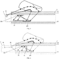
- FIG. 1 is a first schematic stack diagram of a liquid crystal display fingerprint recognition apparatus according to an embodiment of the present application.
- the liquid crystal display fingerprint recognition apparatus may include: a display module 1 and a fingerprint module 2.
- the display module 1 includes a liquid crystal panel 11 and a backlight module 12 that is disposed behind the liquid crystal panel 11.
- the fingerprint module 2 may also be referred to as an under-screen fingerprint recognition system, which may include a fingerprint light source 21, a reflection unit 22 and a fingerprint sensor 23.
- the liquid crystal panel 11 may be located above the backlight module 12.
- the display module 1 may further include a cover plate 13, and the liquid crystal panel 11 may be located between the cover plate 13 and the backlight module 12.
- the reflection unit 22 and the fingerprint sensor 23 are disposed between the liquid crystal panel 11 and the backlight module 12.
- a portion perpendicular to the reflection unit 22 and the fingerprint sensor 23 between the liquid crystal panel 11 and the backlight module 12 in the direction toward the liquid crystal panel 11 is a part of the liquid crystal panel 11, or is empty, or is a part of the cover plate 13, or, and it may be other non-display components.
- the reflection unit 22 and the fingerprint sensor 23 disposed between the liquid crystal panel 11 and the backlight module 12 may block the light from the backlight module 12 to the liquid crystal panel 11. Even if the portion perpendicular to the reflection unit 22 and the fingerprint sensor 23 in the direction toward the liquid crystal panel 11 is a part of the liquid crystal panel 11, such portion cannot display and is presented as a non-display area of the display module 1.
- the reflection unit 22 and the fingerprint sensor 23 can be disposed in an area between the liquid crystal panel 11 and the backlight module 12, which is perpendicular to the non-display area of the display module 1.
- the non-display area of the display module 1 may be a bottom non-display area of the display module 1, or may be a frame non-display area of the display module 1. Disposing the reflection unit 22 and the fingerprint sensor 23 of the fingerprint module 2 in an area between the liquid crystal panel 11 and the backlight module 12 perpendicular to a non-display area of the display module 1, can ensure the display effect of the display area of the display module 1.
- the reflection unit 22 may have a reflection surface that is disposed toward the liquid crystal panel 11 to receive the light that is emitted by the fingerprint light source 21, then is reflected, and then is incident through the liquid crystal panel 11. If as shown in FIG. 1 , the reflection unit 22 has one reflection surface, then the reflection surface of the reflection unit 22 may also be toward the photosensitive surface of the fingerprint sensor 23 and is further configured to reflect the light into the photosensitive surface of the fingerprint sensor 23.
- the liquid crystal panel 11 and the fingerprint sensor 23 may be disposed in different directions of the reflection surface of the reflection unit 22, where the different directions of the reflection surface of the reflection unit 22 may be distinguished by an optical axis of the reflection unit 22, that is, the different directions may refer to different directions on both sides of the optical axis of the reflection surface of the reflection unit 22.
- the liquid crystal panel 11 may be located on one side of the optical axis of the reflection surface of the reflection unit 22, and the fingerprint sensor 23 may be located on the other side of the optical axis of the reflection surface of the reflection unit 22. If the reflection unit 22 has two reflection surfaces, then one reflection surface may be disposed toward the liquid crystal panel 11, and the other reflection surface may be disposed toward the photosensitive surface of the fingerprint sensor 23. That is, the liquid crystal panel 11 and the fingerprint sensor 23 may be respectively located in different directions toward the two different reflection surfaces.
- the reflection surface of the reflection unit 22 may be a plane that is parallel to the liquid crystal panel 11, and the sensing surface of the fingerprint sensor 23 may be substantially parallel to the reflection surface of the reflection unit 22.
- the display module 1 can be referred to as an LCD display module, and the cover plate 13 can be a glass cover plate.
- the backlight module 12 further includes a backlight source (not shown) to provide light to the liquid crystal panel 11, and the liquid crystal panel 11 can implement display function under the irradiation of the light emitted by the backlight source.
- the backlight source may be located at a side end of a light guide plate (not shown) in the backlight module 12 to transmit light to the liquid crystal panel 11 through the light guide plate.
- the backlight can be a white light emitting diode (LED).
- the fingerprint light source 21 can be used to provide light for fingerprint detection.
- the reflection unit 22 and the fingerprint sensor 23 of the fingerprint module 2 are disposed between the liquid crystal panel 11 and the backlight module 12, and the reflection surface of the reflection unit 23 can be disposed toward the liquid crystal panel 11 so that the light emitted by the fingerprint light source 21 is reflected by the finger pressing on the cover 11, passes through the cover plate 13 and the liquid crystal panel 12 in sequence, and then is incident on the reflection surface of the reflection unit 22 between the liquid crystal panel 11 and the backlight module 12, i.e. below the liquid crystal panel 11, and the reflection surface of the reflection unit 22 reflects the incident light.
- the reflection surface of the reflection unit 22 is also toward the photosensitive surface of the fingerprint sensor 23, and is configured to reflect the incident light to the photosensitive surface of the fingerprint sensor 23, so that the fingerprint image data for fingerprint recognition is generated on the photosensitive surface of the fingerprint sensor 23.
- the reflection surface of the reflection unit 22 may be a specular imaging element having a high reflectivity, and generally, the reflection can be implemented by an aluminum film or a silver mirror. Certainly, the reflection surface of the reflection unit 22 may also be implemented in other manners, which will not be detailed herein.
- the reflection unit 22 may be, for example, a reflecting mirror. It should be noted that the reflection unit 22 may also be other components that can perform light reflection, and is not limited to the reflecting mirror which is only a possible example. The embodiments of the present application do not limit this.
- a field of view range of the fingerprint sensor 23 is located in the display area of the display module 1, that is, when a finger presses on the display module 1, the fingerprint sensor 23 may detect the fingerprint image data for fingerprint recognition.
- the fingerprint sensor 23 may be referred to as an optical sensor, an image sensor, an optical fingerprint sensor, an optical inductor, or a fingerprint detecting inductor, etc.
- the light emitted by the fingerprint light source 21 is reflected by the finger, passes through the cover plate 13 and the liquid crystal panel 12 in sequence, and then is incident onto the reflection surface of the reflection unit 22 , the received light is reflected by the reflection surface of the reflection unit 22 to the photosensitive surface of the fingerprint sensor 23, so that the fingerprint sensor 23 generates a fingerprint image according to the received light, and then performs fingerprint detection.
- the liquid crystal display fingerprint recognition apparatus may include: a display module and a fingerprint module; where the display module includes a liquid crystal panel and a backlight module that is disposed behind the liquid crystal panel; the fingerprint module includes a fingerprint light source, a reflection unit and a fingerprint sensor, and the reflection unit and the fingerprint sensor are disposed between the liquid crystal panel and the backlight module; the reflection unit has a reflection surface disposed toward the liquid crystal panel to receive light that is emitted by the fingerprint light source, then is reflected, and then is incident through the liquid crystal panel; the reflection unit is further configured to reflect the light to a photosensitive surface of the fingerprint sensor.
- the liquid crystal display fingerprint recognition apparatus can dispose the reflection unit and the fingerprint sensor of the fingerprint module between the liquid crystal panel and the backlight module of the display module, and the light incident through the liquid crystal panel is reflected by the reflection unit to the photosensitive surface of the fingerprint sensor, which prevents fingerprint light from being blocked by the backlight module of the LCD; the light is reflected by the reflection unit, which realizes an under-screen optical signal detection loop of optical fingerprint for the LCD, and then realizes the under-screen optical fingerprint recognition for the LCD.
- FIG. 2 is a second schematic stack diagram of a liquid crystal display fingerprint recognition apparatus according to an embodiment of the present application.
- the liquid crystal display fingerprint recognition module is based on what is shown in FIG. 1 , where the fingerprint module 2 may further include a transmission unit 25.
- the transmission unit 25 may be disposed between the liquid crystal panel 11 and the reflection unit 22, that is, a surface of the transmission unit 25 may be toward the liquid crystal panel 11 and another surface may be toward the reflection surface of the reflection unit 22, so as to transmit the light incident through the liquid crystal panel 11 to the reflection surface of the reflection unit 22.
- the transmission unit 25 may be an optical imaging element, and can also be referred to as a lens.
- the transmission unit 25 may have a spherical or aspherical optical transmission structure for focusing incident light onto the reflection surface of the reflection unit 22, and in the present embodiment, the incident light may specifically be the light incident through the liquid crystal panel 11.
- the transmission unit 25 may be a lens or a structure composed of a plurality of lenses.
- the lens of the transmission unit 25 may be generally made of a resin material or a glass material.
- the optical axis of the transmission unit 25 may be perpendicular to the optical axis of the reflection unit 22. Certainly, the optical axis of the transmission unit 25 is not perpendicular to the optical axis of the reflection unit 22, for example nearly perpendicular. The optical axis of the transmission unit 25 is perpendicular to the optical axis of the reflection unit 22, so that the light transmitted by the transmission unit 25 is incident on the reflection surface of the reflection unit 22 as much as possible, thereby avoiding omission of the light and ensuring the clarity and integrity of the fingerprint image, and thus ensuring the accuracy of fingerprint detection.
- a surface of the transmission unit 25 may be toward the liquid crystal panel 11 to receive the light incident through the liquid crystal panel 11; another surface of the transmission unit 11 is toward the reflection surface of the reflection unit 23 to transmit the light incident through the transmission unit 25 to the reflection surface of the reflection unit 23.
- reflection surface of the reflection unit 25 is also toward the photosensitive surface of the fingerprint sensor 23, so as to reflect the light to the photosensitive surface of the fingerprint sensor 23.
- the reflection unit 22, the fingerprint sensor 23 and the transmission unit 25 of the fingerprint module 2 may be an integrated module, which can effectively protect the reflection unit.
- the light that is incident through the liquid crystal panel is transmitted to the reflection surface of the reflection unit by the transmission unit disposed between the liquid crystal panel and the reflection unit, which improves the focus of the fingerprint light, makes a fingerprint image generated based on the fingerprint light clearer, and ensures the accuracy of fingerprint detection.
- the fingerprint light source 21 may be located at a side end of the liquid crystal panel 11 near a non-display area.
- the example in which the fingerprint light source 21 is located at the side end of the liquid crystal panel 11 near the non-display area is shown in FIG. 1 .
- the fingerprint light source 21 is located at a side end of the liquid crystal panel 11, near the non-display area, which can avoid display interference caused by the fingerprint light source 21 and ensure the display effect of the display module, while the under-screen optical fingerprint recognition can be realized for the LCD.
- the fingerprint module 2 further includes: a printed circuit board (PCB) 24.
- the PCB 24 may be connected to the fingerprint sensor 23; the fingerprint source 21 may be located on the PCB 24.
- the PCB 24 may be a hard PCB or a flexible printed circuit board (FPCB).
- FPCB flexible printed circuit board
- the FPCB is taken as the PCB 24 for illustrating.
- the example of taking the hard PCB as the PCB 24 is similar to the FPCB and will not be repeated herein.
- the fingerprint light source 21 may also be located between the liquid crystal panel 11 and the backlight module 12. If the fingerprint light source 21 can be located between the liquid crystal panel 11 and the backlight module 12, and the light emitting surface of the fingerprint light source 21 is toward the liquid crystal panel 11.
- the fingerprint light source 21 is disposed between the liquid crystal panel 11 and the backlight module 12, which improves the integration of the liquid crystal display fingerprint recognition apparatus.
- the fingerprint light source 21 as shown above may be an infrared light source regardless of the position of the fingerprint light source 21.
- the infrared light source may be an infrared light source having a wavelength of 850 nm.
- the infrared light source may be, for example, an infrared LED light source, an infrared vertical cavity surface emitting laser (VCSEL), an infrared laser diode, etc.
- the fingerprint module 2 further includes: an infrared filter (not shown) for filtering out the visible light other than the infrared light through the infrared filter.
- the infrared filter may be located on a surface of the reflection unit 22 near the fingerprint sensor 23 as shown in FIG. 1 or FIG. 2 ; or a surface of the fingerprint sensor 23 near the reflection unit 22 as shown in FIG. 1 or FIG. 2 .
- the infrared filter may be located on a light incident surface or a light exit surface of the transmission unit 25 in FIG. 2 .
- the fingerprint light source is set as an infrared light source, so that the fingerprint light of the fingerprint detection is infrared light, which can avoid the interference of the fingerprint light on the visible light source for display, and ensure the display effect of the display module; and at the same time, the interference of the visible light source on the fingerprint light is also avoided, and the accuracy of the fingerprint detection is effectively ensured.
- the following takes an example of two reflection units for illustration of the structure of the liquid crystal display fingerprint recognition apparatus, with reference to a plurality of examples. It should be noted that, in the liquid crystal display fingerprint recognition apparatus provided by the following embodiments, reference may be made to the above description for introduction of components that are the same as or similar to the components of the fingerprint module provided in FIG. 1 and FIG. 2 above, and the details will not be repeated below.
- FIG. 3 is a third schematic stack diagram of a liquid crystal display fingerprint recognition apparatus according to an embodiment of the present application.
- the liquid crystal display fingerprint recognition apparatus may include: a display module 1 and a fingerprint module 2.
- the display module 1 includes a liquid crystal panel 11 and a backlight module 12 that is disposed behind the liquid crystal panel 11.
- the fingerprint module 2 may also be referred to as an under-screen fingerprint recognition system that may include a fingerprint light source 21, a first reflection unit 221, a second reflection unit 222 and a fingerprint sensor 23.
- the liquid crystal panel 11 may be located above the backlight module 12.
- the display module 1 may further include a cover plate 13, and the liquid crystal panel 11 may be located between the cover plate 13 and the backlight module 12.
- the first reflection unit 221, the second reflection unit 222 and the fingerprint sensor 23 are disposed between the liquid crystal panel 11 and the backlight module 12.
- a portion perpendicular to the first reflection unit 221, the second reflection unit 222 and the fingerprint sensor 23 between the liquid crystal panel 11 and the backlight module 12 in the direction toward the liquid crystal panel 11 is a part of the liquid crystal panel 11, or is empty, or is a part of the cover plate 13, or, it may be other non-display components.
- the first reflection unit 221, the second reflection unit 222 and the fingerprint sensor 23 that are disposed between the liquid crystal panel 11 and the backlight module 12 may block the light from the backlight module 12 to the liquid crystal panel 11. Even if the portion perpendicular to the reflection unit 22 and the fingerprint sensor 23 in the direction toward the liquid crystal panel 11 is a part of the liquid crystal panel 11, such portion cannot display and is presented as a non-display area of the display module 1.
- the first reflection unit 221, the second reflection unit 222 and the fingerprint sensor 23 are disposed in an area between the liquid crystal panel 11 and the backlight module 12, which is perpendicular to the non-display area of the display module 1.
- the non-display area of the display module 1 may be a bottom non-display area of the display module 1, or may be a frame non-display area of the display module 1. Disposing the first reflection unit 221, the second reflection unit 222 and the fingerprint sensor 23 of the fingerprint module 2 in the area perpendicular to the non-display area of the display module 1 between the liquid crystal panel 11 and the backlight module 12 can ensure the display effect of the display area of the display module.
- the first reflection unit 221 If there are two reflection units in the fingerprint module 2, that is, the first reflection unit 221 and the second reflection unit 222.
- the first reflection unit 221 has a reflection surface that is disposed toward the liquid crystal panel 11 to receive the light that is emitted by the fingerprint light source 21, then is reflected, and then is incident through the liquid crystal panel 11. As shown in FIG. 3 , if the first reflection unit 221 has one reflection surface, then the reflection surface of the first reflection unit 221 is also toward the reflection surface of the second reflection unit 222 and is further configured to reflect the light onto the reflection surface of the second reflection unit 222.
- the liquid crystal panel 11 and the second reflection unit 222 may be disposed in different directions of the reflection surface of the first reflection unit 221, where the different directions of the reflection surface of the first reflection unit 221 may be distinguished by the optical axis of the first reflection unit 221, that is, the different directions may refer to different directions on both sides of the optical axis of the reflection surface of the first reflection unit 221. That is to say, the liquid crystal panel 11 may be located on one side of the optical axis of the reflection surface of the first reflection unit 221, and the second reflection unit 222 may be located on the other side of the optical axis of the reflection surface of the first reflection unit 221.
- the first reflection unit 221 has two reflection surfaces, one may be disposed toward the liquid crystal panel 11, and the other may be disposed toward the second reflection unit 222. That is, the liquid crystal panel 11 and the second reflection unit 222 may be respectively located in different directions toward the two different reflection surfaces.
- the second reflection unit 222 may also have a reflection surface that is disposed toward the reflection surface of the first reflection unit 221 to receive the light reflected by the reflection surface of the first reflection unit 221. As shown in FIG. 3 , if the second reflection unit 222 has one reflection surface, then the reflection surface of the second reflection unit 222 is also towards the photosensitive surface of the fingerprint sensor 23 to transmit the light reflected by the reflection surface of the second reflection unit 222 to the photosensitive surface of the fingerprint sensor 23.
- the first reflection unit 221 and the fingerprint sensor 23 may be located in different directions of the reflection surface of the second reflection unit 222, where the different directions of the reflection surface of the second reflection unit 222 may be distinguished by the optical axis of the second reflection unit 222, that is, the different directions may refer to different directions on both sides of the optical axis of the reflection surface of the second reflection unit 222.
- the first reflection unit 221 may be located on one side of the optical axis of the reflection surface of the second reflection unit 222
- the fingerprint sensor 23 may be located on the other side of the optical axis of the reflection surface of the second reflection unit 222.
- the second reflection unit 222 has two reflection surfaces, one reflection surface may be disposed toward the first reflection unit 221, and the other reflection surface may be disposed toward the fingerprint sensor 23. That is, the first reflection unit 221 and the fingerprint sensor 23 may be respectively located in different directions toward the two different reflection surfaces.
- the reflection surface of the second reflection unit 222 may be substantially parallel to the reflection surface of the first reflection unit 221, which means that the optical axis of the reflection surface of the second reflection unit 222 is parallel or nearly parallel to the optical axis of the reflection surface of the first reflection unit 221.
- the first reflection unit 221 and the second reflection unit 222 may be the same as or similar to the reflection unit 22 in the liquid crystal display fingerprint recognition apparatus shown in above FIG. 1 and FIG. 2 , and reference may be made to the above for the details, which will not be repeated herein.
- the fingerprint light source 21 may be the same as or similar to the fingerprint light source 21 in the liquid crystal display fingerprint recognition apparatus of above FIG. 1 or FIG. 2 , and reference may be made to the above for the details, which will not be repeated herein.
- the light emitted by the fingerprint light source 21 is reflected by the finger, then passes through the cover plate 13 and the liquid crystal panel 12 in sequence and then is incident onto the reflection surface of the first reflection unit 221, the received light is reflected by the reflection surface of the first reflection unit 221 to the reflection surface of the second reflection unit 222, and reflected by the reflection surface of the second reflection unit 222 to the photosensitive surface of the fingerprint sensor 23, so that the fingerprint sensor 23 generates a fingerprint image according to the received light, and then performs fingerprint detection.
- the liquid crystal display fingerprint recognition apparatus may include: a display module and a fingerprint module; where the display module includes a liquid crystal panel and a backlight module that is disposed behind the liquid crystal panel; the fingerprint module includes a fingerprint light source, a first reflection unit, a second reflection unit and a fingerprint sensor, and the first reflection unit, the second reflection unit and the fingerprint sensor are located between the liquid crystal panel and the backlight module; and the reflection surface of the first reflection unit is disposed toward the liquid crystal panel to receive the light that is emitted by the fingerprint light source, then is reflected, and then is incident through the liquid crystal panel; the first reflection unit is further configured to make the light reflected by the reflection surface of the first reflection unit incident to the reflection surface of the second reflection unit, and the reflection surface of the second reflection unit is disposed toward the photosensitive surface of the fingerprint sensor, so that the light reflected by the reflection surface of the second reflection unit is incident onto the photosensitive surface of the fingerprint sensor.
- the liquid crystal display fingerprint recognition apparatus can set the first reflection unit, the second reflection unit and the fingerprint sensor between the liquid crystal panel and the backlight module of the display module, and the light incident through the liquid crystal panel is reflected to the photosensitive surface of the fingerprint sensor by the first reflection unit and the second reflection unit in sequence, which prevents fingerprint light being blocked by the backlight module of the LCD; and the light is reflected by the first reflection unit and the second reflection unit, which realizes an under-screen optical signal detection loop of the optical fingerprint for the LCD, and realizes the under-screen optical fingerprint recognition for the LCD.
- the light incident through the liquid crystal panel is reflected to the photosensitive surface of the fingerprint sensor by the first reflection unit and the second reflection unit in sequence, and folding of the optical path is achieved by the first reflection unit and second reflection unit, which shortens the distance between the liquid crystal panel and the backlight module, realizes the thinness of the fingerprint recognition apparatus of the LCD and increases the object distance of the fingerprint sensor at the same time, thereby improving the field of view range of the fingerprint sensor and expanding the visible fingerprint area.
- FIG. 4 is a fourth schematic stack diagram of a liquid crystal display fingerprint recognition apparatus according to an embodiment of the present application. As shown in FIG. 4 , the liquid crystal display fingerprint recognition apparatus is based on what is shown in above FIG. 3 , where the fingerprint module 2 may further include a transmission unit 25.
- the transmission unit 25 may be located between the first reflection unit 221 and the second reflection unit 222, that is, a surface of the transmission unit 25 may be disposed toward the reflection surface of the first reflection unit 221 for receiving the light reflected by the first reflection unit 221, and another surface of the transmission unit 25 is disposed toward the reflection surface of the second reflection unit 222 for transmitting the light reflected by the first reflection unit 221 to the reflection surface of the second reflection unit 222.
- the transmission unit 25 may be the same as or similar to the transmission unit 25 in the liquid crystal display fingerprint recognition apparatus shown in FIG. 1 and FIG. 2 in the above embodiments, and reference may be made to the above for the details, which will not be repeated herein.
- the optical axis of the transmission unit 25 may be perpendicular to both the optical axis of the reflection surface of the first reflection unit 221 and the optical axis of the reflection surface of the second reflection unit 222. Certainly, the optical axis of the transmission unit 25 may not be perpendicular to the optical axis of the reflection surface of the first reflection unit 221, nor to the optical axis of the reflection surface of the second reflection unit 222.
- the optical axis of the transmission unit 25 may be perpendicular to both the optical axis of the reflection surface of the first reflection unit 221 and the optical axis of the reflection surface of the second reflection unit 222, so that the light transmitted by the transmission unit 25 is incident on the reflection surface of the second reflection unit 222 as much as possible is perpendicular to the optical axis, thereby avoiding omission of the light and ensuring the clarity and integrity of the fingerprint image, and thus ensuring the accuracy of fingerprint detection.
- the reflection surface of the first reflection unit 221 is toward the liquid crystal panel 11, and the reflection surface of the first reflection unit 221 is configured to receive the light incident through the liquid crystal panel 11; as shown in FIG. 3 , if there is one reflection surface in the first reflection unit 221, then the reflection surface of the first reflection unit 221 is also toward a surface of the transmission unit 11 to reflect the light incident through the liquid crystal panel 11 to the transmission unit 11.
- the liquid crystal panel 11 and the transmission unit 11 may be located in different directions of the reflection surface of the first reflection unit 221, where the different directions of the reflection surface of the first reflection unit 221 may be distinguished by the optical axis of the first reflection unit 221, that is, the different directions may refer to different directions on both sides of the optical axis of the reflection surface of the first reflection unit 221. That is to say, the liquid crystal panel 11 may be located on one side of the optical axis of the reflection surface of the first reflection unit 221, and the transmission unit 11 may be located on the other side of the optical axis of the reflection surface of the first reflection unit 221. If there are two reflection surfaces in the first reflection unit 221, one reflection surface may be disposed toward the liquid crystal panel 11, and the other reflection surface may be disposed toward the transmission unit 11. That is, the liquid crystal panel 11 and the transmission unit 11 may be respectively located in different directions toward the two different reflection surfaces.
- the reflection surface of the second reflection unit 222 is toward another surface of the transmission unit 25 for receiving the light incident through the transmission unit 25; as shown in FIG. 3 , if there is one reflection surface in the reflection unit 222, the reflection surface of the second reflection unit 222 is also toward the photosensitive surface of the fingerprint sensor 23 to reflect the light incident through the transmission unit 25 to the photosensitive surface of the fingerprint sensor 23.
- the transmission unit 25 and the fingerprint sensor 23 may be located in different directions of the reflection surface of the second reflection unit 222, where the different directions of the reflection surface of the second reflection unit 222 may be distinguished by the optical axis of the second reflection unit 222, that is, the different directions may refer to different directions on both sides of the optical axis of the reflection surface of the second reflection unit 222.
- the transmission unit 25 may be located on one side of the optical axis of the reflection surface of the second reflection unit 222, and the fingerprint sensor 23 is located on the other side of the optical axis of the reflection surface of the second reflection unit 222. If there are two reflection surfaces in the second reflection unit 222, then one reflection surface may be disposed toward the transmission unit 25, and the other reflection surface may be disposed toward the fingerprint sensor 23. That is, the transmission unit 25 and the fingerprint sensor 23 may be respectively located in different directions toward the two different reflection surfaces.
- the second reflection unit 222, the fingerprint sensor 23 and the transmission unit 25 of the fingerprint module 2 may be an integrated module, which can effectively ensure the reflection unit.
- the light emitted by the reflection surface of the first reflection unit is transmitted to the reflection surface of the second reflection unit by the transmission unit disposed between the first reflection unit and the second reflection unit, which improves the focus of the fingerprint light, makes a fingerprint image generated based on the fingerprint light clearer, and ensures the accuracy of fingerprint detection.
- the fingerprint light source 21 may be located at a side end of the liquid crystal panel 11 near a non-display area.
- the example in which the fingerprint light source 21 is located at the side end of the liquid crystal panel 11 near the non-display area is shown in above FIG. 1 .
- the fingerprint light source 21 is located at a side end of the liquid crystal panel 11 near the non-display area, which can avoid display interference caused by the fingerprint light source 21 and ensure the display effect of the display module while the under-screen optical fingerprint recognition can be realized for the LCD.
- the fingerprint module 2 further includes: a PCB 24.
- the PCB 24 may be connected to the fingerprint sensor 23; the fingerprint source 21 may be located on the PCB 24.
- the PCB 24 may be a hard PCB, or a FPCB.
- the FPCB is taken as the PCB 24 for illustrating.
- the example of taking the hard PCB as the PCB 24 is similar to the FPCB and will not be repeated herein.
- the fingerprint light source 21 may also be located between the liquid crystal panel 11 and the backlight module 12. If the fingerprint light source 21 may be located between the liquid crystal panel 11 and the backlight module 12, and the light emitting surface of the fingerprint light source 21 is toward the liquid crystal panel 11.
- the fingerprint light source 21 is disposed between the liquid crystal panel 11 and the backlight module 12, which improves the integration of the liquid crystal display fingerprint recognition apparatus.
- the fingerprint light source 21 as shown above may be an infrared light source regardless of the position of the fingerprint light source 21.
- the infrared light source may be an infrared light source having a wavelength of 850 nm.
- the infrared light source may be, for example, an infrared LED light source, an infrared VCSEL, an infrared laser diode, etc.
- the fingerprint module 2 further includes: an infrared filter (not shown) for filtering out the visible light other than the infrared light through the infrared filter.
- the infrared filter may be located on a surface of the first reflection unit 221 toward the second reflection unit 222 as shown in FIG. 3 or FIG. 4 , or the infrared filter is located on a surface of the second reflection unit 222 toward the fingerprint sensor 23 as shown in FIG. 3 or FIG. 4 ; or the infrared filter is located on a surface of the fingerprint sensor 23 toward the second reflection unit 222 as shown in FIG. 3 or FIG. 4 .
- the infrared filter may be disposed on a light incident surface or a light exit surface of the transmission unit 25 in FIG. 4 .
- the fingerprint light source is set as an infrared light source, so that the fingerprint light of the fingerprint detection is the infrared light, which can avoid the interference of the fingerprint light on the visible light source for display, and ensure the display effect of the display module; and at the same time, the interference of the visible light source on the fingerprint light is avoided, and the accuracy of the fingerprint detection is effectively ensured.
- the fingerprint module provided by the present application may further include other numbers of reflection units, such as three or four reflection units, and correspondingly, the positional relationship of the reflection units is adjusted appropriately, which still fall within the scope of protection of the embodiments of the present application as long as the light incident to the fingerprint sensor is a light reflected by the reflection unit.
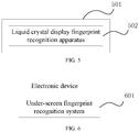
- FIG. 5 is a schematic structural diagram of an electronic device according to the embodiment of the present application.
- the electronic device may include a housing 501 and a liquid crystal display fingerprint recognition apparatus 502.
- the liquid crystal display fingerprint recognition apparatus 502 is located in the housing 501.
- the electronic device may not include the housing 501, and is not limited to the structure shown in FIG.5 .
- the electronic device may also include other components, which will not be detailed herein.
- the liquid crystal display fingerprint recognition apparatus 502 may be the liquid crystal display fingerprint recognition apparatus shown in any of the FIGs. 1 to 4 described above.
- the electronic device may include any of the above liquid crystal display fingerprint recognition apparatus. Since the reflection unit and the fingerprint sensor are disposed between the liquid crystal panel and the backlight module of the display module, and the light incident through the liquid crystal panel is reflected by the reflection unit to the photosensitive surface of the fingerprint sensor, fingerprint light is prevented from being blocked by the backlight module of the LCD; the light is reflected by the reflection unit, which realizes an under-screen optical signal detection loop of the optical fingerprint for the LCD, and then realizes the under-screen optical fingerprint recognition for the LCD.
- An embodiment of the present application further provides an under-screen fingerprint recognition system, for the schematic structural diagram therefore, reference may be specifically made to the fingerprint module in the liquid crystal display fingerprint recognition apparatus according to any one of FIGs. 1-4 described above, which will not be repeated herein.
- the under-screen fingerprint recognition system is applicable to being located under a liquid crystal display module that has a liquid crystal panel and a backlight module to perform under-screen optical fingerprint detection.
- the under-screen fingerprint recognition system includes: a fingerprint light source, a reflection unit and a fingerprint sensor.
- the fingerprint light source is configured to provide light for fingerprint detection, and the reflection unit and the fingerprint sensor are disposed between the liquid crystal panel and the backlight module; the reflection unit has a reflection surface that is disposed toward the liquid crystal panel to receive the light that is emitted by the fingerprint light source, then is reflected, and then is incident through the liquid crystal panel.
- the reflection unit is further configured to reflect the light to the photosensitive surface of the fingerprint sensor; the fingerprint sensor is configured to detect, according to the received light, a fingerprint image of a finger pressing on the liquid crystal display module, and a field of view range of the fingerprint sensor is located in a display area of the liquid crystal display module.
- the under-screen fingerprint recognition system further includes: a transmission unit.
- the transmission unit is located between the liquid crystal panel and the reflection unit to transmit the light incident through the liquid crystal panel to a reflection surface of the reflection unit.
- the reflection unit includes: one reflection unit; the transmission unit is disposed toward the liquid crystal panel to receive the light incident through the liquid crystal panel; the reflection surface of the reflection unit is toward the transmission unit to receive the light incident through the transmission unit; and the reflection surface of the reflection unit is also toward the photosensitive surface of the fingerprint sensor to reflect the light to the photosensitive surface of the fingerprint sensor.
- the reflection unit includes: a first reflection unit and a second reflection unit; a reflection surface of the first reflection unit is toward the liquid crystal panel to receive the light incident through the liquid crystal panel; and the reflection surface of the first reflection unit is also toward a surface of the transmission unit to reflect the light incident through the liquid crystal panel to the transmission unit; a reflection surface of the second reflection unit is toward another surface of the transmission unit to receive light incident through the transmission unit; and the reflection surface of the second reflection unit is also toward the photosensitive surface of the fingerprint sensor to reflect the light incident through the transmission unit to the photosensitive surface of the fingerprint sensor.
- the fingerprint light source is located at a side end of the liquid crystal panel near a non-display area; or it is located between the liquid crystal panel and the backlight module.
- the fingerprint module further includes: a PCB that is connected to the fingerprint sensor; the fingerprint light source is located on the PCB.
- the PCB is a hard PCB, or a FPCB.
- the fingerprint source is an infrared source.
- the under-screen fingerprint recognition system provided by the embodiment of the present invention can reflect the light incident through the liquid crystal panel to the photosensitive surface of the fingerprint sensor, which prevents fingerprint light being blocked by the backlight module of the LCD, and the light is reflected through the reflection unit, which realize an under-screen optical signal detection loop of optical fingerprint for the LCD, and then realizes the under-screen optical fingerprint recognition for the LCD.
- FIG. 6 is a schematic structural diagram of another electronic device according to the embodiment of the present application.
- the electronic device may include an under-screen fingerprint recognition system 601.
- the under-screen fingerprint recognition system 601 may be the fingerprint module 2 in the liquid crystal display fingerprint recognition apparatus shown in any of the above FIGs. 1-4 .
- the electronic device may include any of the above under-screen fingerprint recognition systems. Since the reflection unit and the fingerprint sensor of the under-screen fingerprint recognition system can be disposed between the liquid crystal panel and the backlight module of the display module, and the light incident through the liquid crystal panel is reflected by the reflection unit to the photosensitive surface of the fingerprint sensor, the fingerprint light is prevented from being blocked by the backlight module of the LCD; and the light is reflected by the reflection unit, which realizes an under-screen optical signal detection loop of the optical fingerprint for the LCD, and realizes the under-screen optical fingerprint recognition for the LCD.
- the foregoing program may be stored in a computer readable storage medium, and when the program is executed, the steps of the above method embodiments are performed; while the foregoing storage medium includes: a medium that can store program codes, such as a ROM, a RAM, a magnetic disk, or an optical disk.
Landscapes
- Physics & Mathematics (AREA)
- Engineering & Computer Science (AREA)
- Nonlinear Science (AREA)
- General Physics & Mathematics (AREA)
- Optics & Photonics (AREA)
- Mathematical Physics (AREA)
- Chemical & Material Sciences (AREA)
- Crystallography & Structural Chemistry (AREA)
- Multimedia (AREA)
- Theoretical Computer Science (AREA)
- Human Computer Interaction (AREA)
- Image Input (AREA)
- Devices For Indicating Variable Information By Combining Individual Elements (AREA)
- Liquid Crystal (AREA)
Abstract
Description
- Embodiments of the present application relate to the recognition technology, and in particular, to an under-screen fingerprint recognition system, a liquid crystal display fingerprint recognition apparatus, and an electronic device.
- With the development of electronic technology, display screens of electronic devices are gradually developing to full screen, and the screen ratio is becoming higher and higher, which makes the current mainstream capacitive fingerprint module have nowhere to be placed, and an under-screen optical fingerprint came into being.
- At present, for an organic light-emitting diode (OLED) display screen, the application of under-screen optical fingerprint recognition solution are more and more. The under-screen optical fingerprint solution of the OLED display screen detects a fingerprint by irradiating the finger using light of the screen itself and employing the light transmittance of the OLED display screen.
- However, for a liquid crystal display (LCD), since the light transmittance of the backlight module of the LCD is so poor that an under-screen optical signal detecting loop of an optical fingerprint cannot be formed, thereby the under-screen optical fingerprint recognition cannot be realized.
- The embodiments of the present application provide an under-screen fingerprint recognition system, a liquid crystal display fingerprint recognition apparatus, and an electronic device, so as to implement the under-screen optical fingerprint recognition of an LCD.
- The embodiments of the present invention provide an under-screen fingerprint recognition system that is applicable to being located under a liquid crystal display module that has a liquid crystal panel and a backlight module to perform under-display screen optical fingerprint detection, and the under-screen fingerprint recognition system includes: a fingerprint light source, a reflection unit and a fingerprint sensor;
the fingerprint light source is configured to provide light for fingerprint detection, the reflection unit and the fingerprint sensor are disposed between the liquid crystal panel and the backlight module; the reflection unit has a reflection surface that is disposed toward the liquid crystal panel to receive the light that is emitted by the fingerprint light source, then is reflected, and then is incident through the liquid crystal panel;
the reflection unit is also toward a photosensitive surface of the fingerprint sensor to reflect the light to the photosensitive surface of the fingerprint sensor;
the fingerprint sensor is configured to detect, according to the light received, a fingerprint image of a finger pressing on the liquid crystal display module, and a field of view range of the fingerprint sensor is located in a display area of the liquid crystal display module. - The embodiments of the present application further provide a liquid crystal display fingerprint recognition apparatus, including: a display module and a fingerprint module; where the display module includes a liquid crystal panel and a backlight module that is disposed behind the liquid crystal panel; and the fingerprint module includes a fingerprint light source, a reflection unit and a fingerprint sensor;
the reflection unit and the fingerprint sensor are disposed between the liquid crystal panel and the backlight module; the reflection unit has a reflection surface that is disposed toward the liquid crystal panel to receive light that is emitted by the fingerprint light source, then is reflected, and then is incident through the liquid crystal panel;
the reflection unit is further configured to reflect the light to a photosensitive surface of the fingerprint sensor. - The embodiments of the present application further provide an electronic device, including: the under-screen fingerprint recognition system described above.
- The embodiments of the present application provide an under-screen fingerprint recognition system, a liquid crystal display fingerprint recognition apparatus, and an electronic device, where the under-screen fingerprint recognition system is applicable to being located under a liquid crystal display module that has a liquid crystal panel and a backlight module to perform under-screen optical fingerprint detection, and the under-screen fingerprint recognition system includes: a fingerprint light source, a reflection unit and a fingerprint sensor, the reflection unit and the fingerprint sensor are disposed between the liquid crystal panel and the backlight module; the reflection unit has a reflection surface that is disposed toward the liquid crystal panel to receive light that is emitted by the fingerprint light source, then is reflected, and then is incident through the liquid crystal panel; the reflection unit is further configured to reflect the light to a photosensitive surface of the fingerprint sensor. The reflection unit and the fingerprint sensor of the under-screen fingerprint recognition system are disposed between the liquid crystal panel and the backlight module, and the light incident through the liquid crystal panel is reflected by the reflection unit to the photosensitive surface of the fingerprint sensor, which prevents fingerprint light from being blocked by the backlight module of the LCD; the light is reflected by the reflection unit, and thereby an under-screen optical signal detection loop of the optical fingerprint is realized for the LCD, and then the under-screen optical fingerprint recognition is realized for the LCD.
- In order to more clearly illustrate the technical solutions in the embodiments of the present application or in the prior art, a brief introduction of the drawings used for describing the embodiments or the prior art will be made below. Obviously, the drawings in the following description are some embodiments of the present invention, and for those skilled in the art, other drawings may also be obtained according to these drawings without any creative effort.
-
FIG. 1 is a first schematic stack diagram of a liquid crystal display fingerprint recognition apparatus according to an embodiment of the present application; -
FIG. 2 is a second schematic stack diagram of a liquid crystal display fingerprint recognition apparatus according to an embodiment of the present application; -
FIG. 3 is a third schematic stack diagram of a liquid crystal display fingerprint recognition apparatus according to an embodiment of the present application; -
FIG. 4 is a fourth schematic stack diagram of a liquid crystal display fingerprint recognition apparatus according to an embodiment of the present application; -
FIG. 5 is a schematic structural diagram of an electronic device according to an embodiment of the present application; -
FIG. 6 is a schematic structural diagram of another electronic device according to an embodiment of the present application. - To make the purposes, technical solutions and advantages of the embodiments of the present application clearer, the technical solutions in the embodiments of the present application will be clearly and completely described below with reference to the drawings in the embodiments of the present application. Apparently, the described embodiments are some but not all of the embodiments according to the present application. All other embodiments obtained by those skilled in the art based on the embodiments of the present application without creative efforts fall within the protection scope of the present application.
- All technical and scientific terms used herein have the same meaning as generally understood by those skilled in the art, unless otherwise defined. The terms used in the specification of the present application are only in order to describe the purpose of the specific embodiment, but are not intended to limit the present application. The term "and/or" used herein includes any and all combinations of one or more related listed items. Some embodiments of the present application are described below with reference to the accompanying drawings. The following embodiments and the features in the embodiments may be combined with each other when there's no conflict.
- The following embodiments of the present application provide an under-screen fingerprint recognition system, a liquid crystal display fingerprint recognition apparatus and an electronic device, which can be applied to any electronic device having an LCD with an under-screen optical fingerprint recognition function, such as a smart phone, a notebook computer, a wearable device, and a household appliances. The under-screen optical fingerprint of the LCD can be partially implemented in a display area of the LCD or in the full screen.
- The embodiments of the present application will be described below in combination with a plurality of examples.
- In the liquid crystal display fingerprint recognition apparatus provided by the embodiments of the present application, the number of the reflection units of the fingerprint module may be one or more, and in the following, one reflection unit is taken as an example first for illustration of the liquid crystal display fingerprint recognition apparatus, in combination with a plurality of examples.
-
FIG. 1 is a first schematic stack diagram of a liquid crystal display fingerprint recognition apparatus according to an embodiment of the present application. As shown inFIG. 1 , the liquid crystal display fingerprint recognition apparatus may include: adisplay module 1 and afingerprint module 2. Thedisplay module 1 includes aliquid crystal panel 11 and abacklight module 12 that is disposed behind theliquid crystal panel 11. Thefingerprint module 2 may also be referred to as an under-screen fingerprint recognition system, which may include afingerprint light source 21, areflection unit 22 and afingerprint sensor 23. - The
liquid crystal panel 11 may be located above thebacklight module 12. Thedisplay module 1 may further include acover plate 13, and theliquid crystal panel 11 may be located between thecover plate 13 and thebacklight module 12. - The
reflection unit 22 and thefingerprint sensor 23 are disposed between theliquid crystal panel 11 and thebacklight module 12. A portion perpendicular to thereflection unit 22 and thefingerprint sensor 23 between theliquid crystal panel 11 and thebacklight module 12 in the direction toward theliquid crystal panel 11 is a part of theliquid crystal panel 11, or is empty, or is a part of thecover plate 13, or, and it may be other non-display components. Thereflection unit 22 and thefingerprint sensor 23 disposed between theliquid crystal panel 11 and thebacklight module 12 may block the light from thebacklight module 12 to theliquid crystal panel 11. Even if the portion perpendicular to thereflection unit 22 and thefingerprint sensor 23 in the direction toward theliquid crystal panel 11 is a part of theliquid crystal panel 11, such portion cannot display and is presented as a non-display area of thedisplay module 1. - Therefore, the
reflection unit 22 and thefingerprint sensor 23 can be disposed in an area between theliquid crystal panel 11 and thebacklight module 12, which is perpendicular to the non-display area of thedisplay module 1. The non-display area of thedisplay module 1 may be a bottom non-display area of thedisplay module 1, or may be a frame non-display area of thedisplay module 1. Disposing thereflection unit 22 and thefingerprint sensor 23 of thefingerprint module 2 in an area between theliquid crystal panel 11 and thebacklight module 12 perpendicular to a non-display area of thedisplay module 1, can ensure the display effect of the display area of thedisplay module 1. - The
reflection unit 22 may have a reflection surface that is disposed toward theliquid crystal panel 11 to receive the light that is emitted by thefingerprint light source 21, then is reflected, and then is incident through theliquid crystal panel 11. If as shown inFIG. 1 , thereflection unit 22 has one reflection surface, then the reflection surface of thereflection unit 22 may also be toward the photosensitive surface of thefingerprint sensor 23 and is further configured to reflect the light into the photosensitive surface of thefingerprint sensor 23. Theliquid crystal panel 11 and thefingerprint sensor 23 may be disposed in different directions of the reflection surface of thereflection unit 22, where the different directions of the reflection surface of thereflection unit 22 may be distinguished by an optical axis of thereflection unit 22, that is, the different directions may refer to different directions on both sides of the optical axis of the reflection surface of thereflection unit 22. That is to say, theliquid crystal panel 11 may be located on one side of the optical axis of the reflection surface of thereflection unit 22, and thefingerprint sensor 23 may be located on the other side of the optical axis of the reflection surface of thereflection unit 22. If thereflection unit 22 has two reflection surfaces, then one reflection surface may be disposed toward theliquid crystal panel 11, and the other reflection surface may be disposed toward the photosensitive surface of thefingerprint sensor 23. That is, theliquid crystal panel 11 and thefingerprint sensor 23 may be respectively located in different directions toward the two different reflection surfaces. - If there is one
reflection unit 22 in thefingerprint module 2, then the reflection surface of thereflection unit 22 may be a plane that is parallel to theliquid crystal panel 11, and the sensing surface of thefingerprint sensor 23 may be substantially parallel to the reflection surface of thereflection unit 22. - In the present embodiment, the
display module 1 can be referred to as an LCD display module, and thecover plate 13 can be a glass cover plate. Thebacklight module 12 further includes a backlight source (not shown) to provide light to theliquid crystal panel 11, and theliquid crystal panel 11 can implement display function under the irradiation of the light emitted by the backlight source. The backlight source may be located at a side end of a light guide plate (not shown) in thebacklight module 12 to transmit light to theliquid crystal panel 11 through the light guide plate. The backlight can be a white light emitting diode (LED). - The
fingerprint light source 21 can be used to provide light for fingerprint detection. Thereflection unit 22 and thefingerprint sensor 23 of thefingerprint module 2 are disposed between theliquid crystal panel 11 and thebacklight module 12, and the reflection surface of thereflection unit 23 can be disposed toward theliquid crystal panel 11 so that the light emitted by thefingerprint light source 21 is reflected by the finger pressing on thecover 11, passes through thecover plate 13 and theliquid crystal panel 12 in sequence, and then is incident on the reflection surface of thereflection unit 22 between theliquid crystal panel 11 and thebacklight module 12, i.e. below theliquid crystal panel 11, and the reflection surface of thereflection unit 22 reflects the incident light. The reflection surface of thereflection unit 22 is also toward the photosensitive surface of thefingerprint sensor 23, and is configured to reflect the incident light to the photosensitive surface of thefingerprint sensor 23, so that the fingerprint image data for fingerprint recognition is generated on the photosensitive surface of thefingerprint sensor 23. - The reflection surface of the
reflection unit 22 may be a specular imaging element having a high reflectivity, and generally, the reflection can be implemented by an aluminum film or a silver mirror. Certainly, the reflection surface of thereflection unit 22 may also be implemented in other manners, which will not be detailed herein. Thereflection unit 22 may be, for example, a reflecting mirror. It should be noted that thereflection unit 22 may also be other components that can perform light reflection, and is not limited to the reflecting mirror which is only a possible example. The embodiments of the present application do not limit this. - A field of view range of the
fingerprint sensor 23 is located in the display area of thedisplay module 1, that is, when a finger presses on thedisplay module 1, thefingerprint sensor 23 may detect the fingerprint image data for fingerprint recognition. Thefingerprint sensor 23 may be referred to as an optical sensor, an image sensor, an optical fingerprint sensor, an optical inductor, or a fingerprint detecting inductor, etc. - The light emitted by the
fingerprint light source 21 is reflected by the finger, passes through thecover plate 13 and theliquid crystal panel 12 in sequence, and then is incident onto the reflection surface of thereflection unit 22 , the received light is reflected by the reflection surface of thereflection unit 22 to the photosensitive surface of thefingerprint sensor 23, so that thefingerprint sensor 23 generates a fingerprint image according to the received light, and then performs fingerprint detection. - The liquid crystal display fingerprint recognition apparatus provided by the embodiment of the present application may include: a display module and a fingerprint module; where the display module includes a liquid crystal panel and a backlight module that is disposed behind the liquid crystal panel; the fingerprint module includes a fingerprint light source, a reflection unit and a fingerprint sensor, and the reflection unit and the fingerprint sensor are disposed between the liquid crystal panel and the backlight module; the reflection unit has a reflection surface disposed toward the liquid crystal panel to receive light that is emitted by the fingerprint light source, then is reflected, and then is incident through the liquid crystal panel; the reflection unit is further configured to reflect the light to a photosensitive surface of the fingerprint sensor. The liquid crystal display fingerprint recognition apparatus can dispose the reflection unit and the fingerprint sensor of the fingerprint module between the liquid crystal panel and the backlight module of the display module, and the light incident through the liquid crystal panel is reflected by the reflection unit to the photosensitive surface of the fingerprint sensor, which prevents fingerprint light from being blocked by the backlight module of the LCD; the light is reflected by the reflection unit, which realizes an under-screen optical signal detection loop of optical fingerprint for the LCD, and then realizes the under-screen optical fingerprint recognition for the LCD.
- On the basis of the above a liquid crystal display fingerprint recognition apparatus shown in
FIG. 1 , an embodiment of the present application may also provide a liquid crystal display fingerprint recognition apparatus.FIG. 2 is a second schematic stack diagram of a liquid crystal display fingerprint recognition apparatus according to an embodiment of the present application. As shown inFIG. 2 , the liquid crystal display fingerprint recognition module is based on what is shown inFIG. 1 , where thefingerprint module 2 may further include atransmission unit 25. - The
transmission unit 25 may be disposed between theliquid crystal panel 11 and thereflection unit 22, that is, a surface of thetransmission unit 25 may be toward theliquid crystal panel 11 and another surface may be toward the reflection surface of thereflection unit 22, so as to transmit the light incident through theliquid crystal panel 11 to the reflection surface of thereflection unit 22. - The
transmission unit 25 may be an optical imaging element, and can also be referred to as a lens. Thetransmission unit 25 may have a spherical or aspherical optical transmission structure for focusing incident light onto the reflection surface of thereflection unit 22, and in the present embodiment, the incident light may specifically be the light incident through theliquid crystal panel 11. Thetransmission unit 25 may be a lens or a structure composed of a plurality of lenses. The lens of thetransmission unit 25 may be generally made of a resin material or a glass material. - The optical axis of the
transmission unit 25 may be perpendicular to the optical axis of thereflection unit 22. Certainly, the optical axis of thetransmission unit 25 is not perpendicular to the optical axis of thereflection unit 22, for example nearly perpendicular. The optical axis of thetransmission unit 25 is perpendicular to the optical axis of thereflection unit 22, so that the light transmitted by thetransmission unit 25 is incident on the reflection surface of thereflection unit 22 as much as possible, thereby avoiding omission of the light and ensuring the clarity and integrity of the fingerprint image, and thus ensuring the accuracy of fingerprint detection. - If there is one reflection unit in the
fingerprint module 2, a surface of thetransmission unit 25 may be toward theliquid crystal panel 11 to receive the light incident through theliquid crystal panel 11; another surface of thetransmission unit 11 is toward the reflection surface of thereflection unit 23 to transmit the light incident through thetransmission unit 25 to the reflection surface of thereflection unit 23. - And the reflection surface of the
reflection unit 25 is also toward the photosensitive surface of thefingerprint sensor 23, so as to reflect the light to the photosensitive surface of thefingerprint sensor 23. - In the liquid crystal display fingerprint recognition apparatus shown in
FIG. 1 or FIG. 2 , thereflection unit 22, thefingerprint sensor 23 and thetransmission unit 25 of thefingerprint module 2 may be an integrated module, which can effectively protect the reflection unit. - In the liquid crystal display fingerprint recognition apparatus provided by the embodiment, the light that is incident through the liquid crystal panel is transmitted to the reflection surface of the reflection unit by the transmission unit disposed between the liquid crystal panel and the reflection unit, which improves the focus of the fingerprint light, makes a fingerprint image generated based on the fingerprint light clearer, and ensures the accuracy of fingerprint detection.
- Optionally, in the liquid crystal display fingerprint recognition apparatus shown in
FIG. 1 or FIG. 2 , thefingerprint light source 21 may be located at a side end of theliquid crystal panel 11 near a non-display area. The example in which thefingerprint light source 21 is located at the side end of theliquid crystal panel 11 near the non-display area is shown inFIG. 1 . - The
fingerprint light source 21 is located at a side end of theliquid crystal panel 11, near the non-display area, which can avoid display interference caused by thefingerprint light source 21 and ensure the display effect of the display module, while the under-screen optical fingerprint recognition can be realized for the LCD. - Optionally, the
fingerprint module 2 further includes: a printed circuit board (PCB) 24. ThePCB 24 may be connected to thefingerprint sensor 23; thefingerprint source 21 may be located on thePCB 24. - Optionally, the
PCB 24 may be a hard PCB or a flexible printed circuit board (FPCB). - It should be noted that in
FIG. 1 or FIG. 2 , the FPCB is taken as thePCB 24 for illustrating. The example of taking the hard PCB as thePCB 24 is similar to the FPCB and will not be repeated herein. - Optionally, in another example, the
fingerprint light source 21 may also be located between theliquid crystal panel 11 and thebacklight module 12. If thefingerprint light source 21 can be located between theliquid crystal panel 11 and thebacklight module 12, and the light emitting surface of thefingerprint light source 21 is toward theliquid crystal panel 11. - In the liquid crystal display fingerprint recognition apparatus provided in the embodiment, the
fingerprint light source 21 is disposed between theliquid crystal panel 11 and thebacklight module 12, which improves the integration of the liquid crystal display fingerprint recognition apparatus. - Optionally, the
fingerprint light source 21 as shown above may be an infrared light source regardless of the position of thefingerprint light source 21. The infrared light source may be an infrared light source having a wavelength of 850 nm. The infrared light source may be, for example, an infrared LED light source, an infrared vertical cavity surface emitting laser (VCSEL), an infrared laser diode, etc. - Optionally, if the
fingerprint source 21 is an infrared light source, in order to avoid interference of visible light on fingerprint detection, thefingerprint module 2 further includes: an infrared filter (not shown) for filtering out the visible light other than the infrared light through the infrared filter. - In an implementation, the infrared filter may be located on a surface of the
reflection unit 22 near thefingerprint sensor 23 as shown inFIG. 1 or FIG. 2 ; or a surface of thefingerprint sensor 23 near thereflection unit 22 as shown inFIG. 1 or FIG. 2 . - In another implementation, the infrared filter may be located on a light incident surface or a light exit surface of the
transmission unit 25 inFIG. 2 . - In the liquid crystal display fingerprint recognition apparatus provided by the embodiment, the fingerprint light source is set as an infrared light source, so that the fingerprint light of the fingerprint detection is infrared light, which can avoid the interference of the fingerprint light on the visible light source for display, and ensure the display effect of the display module; and at the same time, the interference of the visible light source on the fingerprint light is also avoided, and the accuracy of the fingerprint detection is effectively ensured.
- The following takes an example of two reflection units for illustration of the structure of the liquid crystal display fingerprint recognition apparatus, with reference to a plurality of examples. It should be noted that, in the liquid crystal display fingerprint recognition apparatus provided by the following embodiments, reference may be made to the above description for introduction of components that are the same as or similar to the components of the fingerprint module provided in
FIG. 1 and FIG. 2 above, and the details will not be repeated below. -
FIG. 3 is a third schematic stack diagram of a liquid crystal display fingerprint recognition apparatus according to an embodiment of the present application. As shown inFIG. 3 , the liquid crystal display fingerprint recognition apparatus may include: adisplay module 1 and afingerprint module 2. Thedisplay module 1 includes aliquid crystal panel 11 and abacklight module 12 that is disposed behind theliquid crystal panel 11. Thefingerprint module 2 may also be referred to as an under-screen fingerprint recognition system that may include afingerprint light source 21, afirst reflection unit 221, asecond reflection unit 222 and afingerprint sensor 23. - The
liquid crystal panel 11 may be located above thebacklight module 12. Thedisplay module 1 may further include acover plate 13, and theliquid crystal panel 11 may be located between thecover plate 13 and thebacklight module 12. - The
first reflection unit 221, thesecond reflection unit 222 and thefingerprint sensor 23 are disposed between theliquid crystal panel 11 and thebacklight module 12. A portion perpendicular to thefirst reflection unit 221, thesecond reflection unit 222 and thefingerprint sensor 23 between theliquid crystal panel 11 and thebacklight module 12 in the direction toward theliquid crystal panel 11 is a part of theliquid crystal panel 11, or is empty, or is a part of thecover plate 13, or, it may be other non-display components. Thefirst reflection unit 221, thesecond reflection unit 222 and thefingerprint sensor 23 that are disposed between theliquid crystal panel 11 and thebacklight module 12 may block the light from thebacklight module 12 to theliquid crystal panel 11. Even if the portion perpendicular to thereflection unit 22 and thefingerprint sensor 23 in the direction toward theliquid crystal panel 11 is a part of theliquid crystal panel 11, such portion cannot display and is presented as a non-display area of thedisplay module 1. - Therefore, the
first reflection unit 221, thesecond reflection unit 222 and thefingerprint sensor 23 are disposed in an area between theliquid crystal panel 11 and thebacklight module 12, which is perpendicular to the non-display area of thedisplay module 1. The non-display area of thedisplay module 1 may be a bottom non-display area of thedisplay module 1, or may be a frame non-display area of thedisplay module 1. Disposing thefirst reflection unit 221, thesecond reflection unit 222 and thefingerprint sensor 23 of thefingerprint module 2 in the area perpendicular to the non-display area of thedisplay module 1 between theliquid crystal panel 11 and thebacklight module 12 can ensure the display effect of the display area of the display module. - If there are two reflection units in the
fingerprint module 2, that is, thefirst reflection unit 221 and thesecond reflection unit 222. - The
first reflection unit 221 has a reflection surface that is disposed toward theliquid crystal panel 11 to receive the light that is emitted by thefingerprint light source 21, then is reflected, and then is incident through theliquid crystal panel 11. As shown inFIG. 3 , if thefirst reflection unit 221 has one reflection surface, then the reflection surface of thefirst reflection unit 221 is also toward the reflection surface of thesecond reflection unit 222 and is further configured to reflect the light onto the reflection surface of thesecond reflection unit 222. Theliquid crystal panel 11 and thesecond reflection unit 222 may be disposed in different directions of the reflection surface of thefirst reflection unit 221, where the different directions of the reflection surface of thefirst reflection unit 221 may be distinguished by the optical axis of thefirst reflection unit 221, that is, the different directions may refer to different directions on both sides of the optical axis of the reflection surface of thefirst reflection unit 221. That is to say, theliquid crystal panel 11 may be located on one side of the optical axis of the reflection surface of thefirst reflection unit 221, and thesecond reflection unit 222 may be located on the other side of the optical axis of the reflection surface of thefirst reflection unit 221. If thefirst reflection unit 221 has two reflection surfaces, one may be disposed toward theliquid crystal panel 11, and the other may be disposed toward thesecond reflection unit 222. That is, theliquid crystal panel 11 and thesecond reflection unit 222 may be respectively located in different directions toward the two different reflection surfaces. - The
second reflection unit 222 may also have a reflection surface that is disposed toward the reflection surface of thefirst reflection unit 221 to receive the light reflected by the reflection surface of thefirst reflection unit 221. As shown inFIG. 3 , if thesecond reflection unit 222 has one reflection surface, then the reflection surface of thesecond reflection unit 222 is also towards the photosensitive surface of thefingerprint sensor 23 to transmit the light reflected by the reflection surface of thesecond reflection unit 222 to the photosensitive surface of thefingerprint sensor 23. Thefirst reflection unit 221 and thefingerprint sensor 23 may be located in different directions of the reflection surface of thesecond reflection unit 222, where the different directions of the reflection surface of thesecond reflection unit 222 may be distinguished by the optical axis of thesecond reflection unit 222, that is, the different directions may refer to different directions on both sides of the optical axis of the reflection surface of thesecond reflection unit 222. In other words, thefirst reflection unit 221 may be located on one side of the optical axis of the reflection surface of thesecond reflection unit 222, and thefingerprint sensor 23 may be located on the other side of the optical axis of the reflection surface of thesecond reflection unit 222. If thesecond reflection unit 222 has two reflection surfaces, one reflection surface may be disposed toward thefirst reflection unit 221, and the other reflection surface may be disposed toward thefingerprint sensor 23. That is, thefirst reflection unit 221 and thefingerprint sensor 23 may be respectively located in different directions toward the two different reflection surfaces. - The reflection surface of the
second reflection unit 222 may be substantially parallel to the reflection surface of thefirst reflection unit 221, which means that the optical axis of the reflection surface of thesecond reflection unit 222 is parallel or nearly parallel to the optical axis of the reflection surface of thefirst reflection unit 221. - The
first reflection unit 221 and thesecond reflection unit 222 may be the same as or similar to thereflection unit 22 in the liquid crystal display fingerprint recognition apparatus shown in aboveFIG. 1 and FIG. 2 , and reference may be made to the above for the details, which will not be repeated herein. - The
fingerprint light source 21 may be the same as or similar to thefingerprint light source 21 in the liquid crystal display fingerprint recognition apparatus of aboveFIG. 1 or FIG. 2 , and reference may be made to the above for the details, which will not be repeated herein. - The light emitted by the
fingerprint light source 21 is reflected by the finger, then passes through thecover plate 13 and theliquid crystal panel 12 in sequence and then is incident onto the reflection surface of thefirst reflection unit 221, the received light is reflected by the reflection surface of thefirst reflection unit 221 to the reflection surface of thesecond reflection unit 222, and reflected by the reflection surface of thesecond reflection unit 222 to the photosensitive surface of thefingerprint sensor 23, so that thefingerprint sensor 23 generates a fingerprint image according to the received light, and then performs fingerprint detection. - The liquid crystal display fingerprint recognition apparatus provided by the embodiment of the present application may include: a display module and a fingerprint module; where the display module includes a liquid crystal panel and a backlight module that is disposed behind the liquid crystal panel; the fingerprint module includes a fingerprint light source, a first reflection unit, a second reflection unit and a fingerprint sensor, and the first reflection unit, the second reflection unit and the fingerprint sensor are located between the liquid crystal panel and the backlight module; and the reflection surface of the first reflection unit is disposed toward the liquid crystal panel to receive the light that is emitted by the fingerprint light source, then is reflected, and then is incident through the liquid crystal panel; the first reflection unit is further configured to make the light reflected by the reflection surface of the first reflection unit incident to the reflection surface of the second reflection unit, and the reflection surface of the second reflection unit is disposed toward the photosensitive surface of the fingerprint sensor, so that the light reflected by the reflection surface of the second reflection unit is incident onto the photosensitive surface of the fingerprint sensor. The liquid crystal display fingerprint recognition apparatus can set the first reflection unit, the second reflection unit and the fingerprint sensor between the liquid crystal panel and the backlight module of the display module, and the light incident through the liquid crystal panel is reflected to the photosensitive surface of the fingerprint sensor by the first reflection unit and the second reflection unit in sequence, which prevents fingerprint light being blocked by the backlight module of the LCD; and the light is reflected by the first reflection unit and the second reflection unit, which realizes an under-screen optical signal detection loop of the optical fingerprint for the LCD, and realizes the under-screen optical fingerprint recognition for the LCD.
- In the liquid crystal display fingerprint recognition apparatus provided by the embodiment, the light incident through the liquid crystal panel is reflected to the photosensitive surface of the fingerprint sensor by the first reflection unit and the second reflection unit in sequence, and folding of the optical path is achieved by the first reflection unit and second reflection unit, which shortens the distance between the liquid crystal panel and the backlight module, realizes the thinness of the fingerprint recognition apparatus of the LCD and increases the object distance of the fingerprint sensor at the same time, thereby improving the field of view range of the fingerprint sensor and expanding the visible fingerprint area.
- On the basis of the liquid crystal display fingerprint recognition apparatus shown in above
FIG. 3 , an embodiment of the present application may also provide a liquid crystal display fingerprint recognition apparatus.FIG. 4 is a fourth schematic stack diagram of a liquid crystal display fingerprint recognition apparatus according to an embodiment of the present application. As shown inFIG. 4 , the liquid crystal display fingerprint recognition apparatus is based on what is shown in aboveFIG. 3 , where thefingerprint module 2 may further include atransmission unit 25. - The
transmission unit 25 may be located between thefirst reflection unit 221 and thesecond reflection unit 222, that is, a surface of thetransmission unit 25 may be disposed toward the reflection surface of thefirst reflection unit 221 for receiving the light reflected by thefirst reflection unit 221, and another surface of thetransmission unit 25 is disposed toward the reflection surface of thesecond reflection unit 222 for transmitting the light reflected by thefirst reflection unit 221 to the reflection surface of thesecond reflection unit 222. - The
transmission unit 25 may be the same as or similar to thetransmission unit 25 in the liquid crystal display fingerprint recognition apparatus shown inFIG. 1 and FIG. 2 in the above embodiments, and reference may be made to the above for the details, which will not be repeated herein. - The optical axis of the
transmission unit 25 may be perpendicular to both the optical axis of the reflection surface of thefirst reflection unit 221 and the optical axis of the reflection surface of thesecond reflection unit 222. Certainly, the optical axis of thetransmission unit 25 may not be perpendicular to the optical axis of the reflection surface of thefirst reflection unit 221, nor to the optical axis of the reflection surface of thesecond reflection unit 222. The optical axis of thetransmission unit 25 may be perpendicular to both the optical axis of the reflection surface of thefirst reflection unit 221 and the optical axis of the reflection surface of thesecond reflection unit 222, so that the light transmitted by thetransmission unit 25 is incident on the reflection surface of thesecond reflection unit 222 as much as possible is perpendicular to the optical axis, thereby avoiding omission of the light and ensuring the clarity and integrity of the fingerprint image, and thus ensuring the accuracy of fingerprint detection. - If there are two reflection units in the fingerprint module, that is, the
first reflection unit 221 and thesecond reflection unit 222, then the reflection surface of thefirst reflection unit 221 is toward theliquid crystal panel 11, and the reflection surface of thefirst reflection unit 221 is configured to receive the light incident through theliquid crystal panel 11; as shown inFIG. 3 , if there is one reflection surface in thefirst reflection unit 221, then the reflection surface of thefirst reflection unit 221 is also toward a surface of thetransmission unit 11 to reflect the light incident through theliquid crystal panel 11 to thetransmission unit 11. Theliquid crystal panel 11 and thetransmission unit 11 may be located in different directions of the reflection surface of thefirst reflection unit 221, where the different directions of the reflection surface of thefirst reflection unit 221 may be distinguished by the optical axis of thefirst reflection unit 221, that is, the different directions may refer to different directions on both sides of the optical axis of the reflection surface of thefirst reflection unit 221. That is to say, theliquid crystal panel 11 may be located on one side of the optical axis of the reflection surface of thefirst reflection unit 221, and thetransmission unit 11 may be located on the other side of the optical axis of the reflection surface of thefirst reflection unit 221. If there are two reflection surfaces in thefirst reflection unit 221, one reflection surface may be disposed toward theliquid crystal panel 11, and the other reflection surface may be disposed toward thetransmission unit 11. That is, theliquid crystal panel 11 and thetransmission unit 11 may be respectively located in different directions toward the two different reflection surfaces. - The reflection surface of the
second reflection unit 222 is toward another surface of thetransmission unit 25 for receiving the light incident through thetransmission unit 25; as shown inFIG. 3 , if there is one reflection surface in thereflection unit 222, the reflection surface of thesecond reflection unit 222 is also toward the photosensitive surface of thefingerprint sensor 23 to reflect the light incident through thetransmission unit 25 to the photosensitive surface of thefingerprint sensor 23. Thetransmission unit 25 and thefingerprint sensor 23 may be located in different directions of the reflection surface of thesecond reflection unit 222, where the different directions of the reflection surface of thesecond reflection unit 222 may be distinguished by the optical axis of thesecond reflection unit 222, that is, the different directions may refer to different directions on both sides of the optical axis of the reflection surface of thesecond reflection unit 222. That is to say, thetransmission unit 25 may be located on one side of the optical axis of the reflection surface of thesecond reflection unit 222, and thefingerprint sensor 23 is located on the other side of the optical axis of the reflection surface of thesecond reflection unit 222. If there are two reflection surfaces in thesecond reflection unit 222, then one reflection surface may be disposed toward thetransmission unit 25, and the other reflection surface may be disposed toward thefingerprint sensor 23. That is, thetransmission unit 25 and thefingerprint sensor 23 may be respectively located in different directions toward the two different reflection surfaces. - In the liquid crystal display fingerprint recognition apparatus shown in
FIG. 3 or FIG. 4 , thesecond reflection unit 222, thefingerprint sensor 23 and thetransmission unit 25 of thefingerprint module 2 may be an integrated module, which can effectively ensure the reflection unit. - In the liquid crystal display fingerprint recognition apparatus provided by the embodiment, the light emitted by the reflection surface of the first reflection unit is transmitted to the reflection surface of the second reflection unit by the transmission unit disposed between the first reflection unit and the second reflection unit, which improves the focus of the fingerprint light, makes a fingerprint image generated based on the fingerprint light clearer, and ensures the accuracy of fingerprint detection.
- Optionally, in the liquid crystal display fingerprint recognition apparatus shown in
FIG. 3 or FIG. 4 , thefingerprint light source 21 may be located at a side end of theliquid crystal panel 11 near a non-display area. The example in which thefingerprint light source 21 is located at the side end of theliquid crystal panel 11 near the non-display area is shown in aboveFIG. 1 . - The
fingerprint light source 21 is located at a side end of theliquid crystal panel 11 near the non-display area, which can avoid display interference caused by thefingerprint light source 21 and ensure the display effect of the display module while the under-screen optical fingerprint recognition can be realized for the LCD. - Optionally, the
fingerprint module 2 further includes: aPCB 24. ThePCB 24 may be connected to thefingerprint sensor 23; thefingerprint source 21 may be located on thePCB 24. - Optionally, the
PCB 24 may be a hard PCB, or a FPCB. - It should be noted that in
FIG. 3 or FIG. 4 , the FPCB is taken as thePCB 24 for illustrating. The example of taking the hard PCB as thePCB 24 is similar to the FPCB and will not be repeated herein. - Optionally, in another example, the
fingerprint light source 21 may also be located between theliquid crystal panel 11 and thebacklight module 12. If thefingerprint light source 21 may be located between theliquid crystal panel 11 and thebacklight module 12, and the light emitting surface of thefingerprint light source 21 is toward theliquid crystal panel 11. - In the liquid crystal display fingerprint recognition apparatus provided in the embodiment, the
fingerprint light source 21 is disposed between theliquid crystal panel 11 and thebacklight module 12, which improves the integration of the liquid crystal display fingerprint recognition apparatus. - Optionally, the
fingerprint light source 21 as shown above may be an infrared light source regardless of the position of thefingerprint light source 21. The infrared light source may be an infrared light source having a wavelength of 850 nm. The infrared light source may be, for example, an infrared LED light source, an infrared VCSEL, an infrared laser diode, etc. - Optionally, if the
fingerprint source 21 is an infrared light source, in order to avoid interference of visible light on fingerprint detection, thefingerprint module 2 further includes: an infrared filter (not shown) for filtering out the visible light other than the infrared light through the infrared filter. - In an implementation, the infrared filter may be located on a surface of the
first reflection unit 221 toward thesecond reflection unit 222 as shown inFIG. 3 or FIG. 4 , or the infrared filter is located on a surface of thesecond reflection unit 222 toward thefingerprint sensor 23 as shown inFIG. 3 or FIG. 4 ; or the infrared filter is located on a surface of thefingerprint sensor 23 toward thesecond reflection unit 222 as shown inFIG. 3 or FIG. 4 . - In another implementation, the infrared filter may be disposed on a light incident surface or a light exit surface of the
transmission unit 25 inFIG. 4 . - In the liquid crystal display fingerprint recognition apparatus provided by the embodiment, the fingerprint light source is set as an infrared light source, so that the fingerprint light of the fingerprint detection is the infrared light, which can avoid the interference of the fingerprint light on the visible light source for display, and ensure the display effect of the display module; and at the same time, the interference of the visible light source on the fingerprint light is avoided, and the accuracy of the fingerprint detection is effectively ensured.
- It should be noted that the above embodiments of the present application are only some possible examples of the liquid crystal fingerprint module provided by the present application, the fingerprint module provided by the present application may further include other numbers of reflection units, such as three or four reflection units, and correspondingly, the positional relationship of the reflection units is adjusted appropriately, which still fall within the scope of protection of the embodiments of the present application as long as the light incident to the fingerprint sensor is a light reflected by the reflection unit.
- An embodiment of the present application may further provide an electronic device having the above liquid crystal display fingerprint recognition apparatus.
FIG. 5 is a schematic structural diagram of an electronic device according to the embodiment of the present application. As shown inFIG. 5 , the electronic device may include ahousing 501 and a liquid crystal displayfingerprint recognition apparatus 502. The liquid crystal displayfingerprint recognition apparatus 502 is located in thehousing 501. Certainly, the electronic device may not include thehousing 501, and is not limited to the structure shown inFIG.5 . The electronic device may also include other components, which will not be detailed herein. - The liquid crystal display
fingerprint recognition apparatus 502 may be the liquid crystal display fingerprint recognition apparatus shown in any of theFIGs. 1 to 4 described above. - The electronic device may include any of the above liquid crystal display fingerprint recognition apparatus. Since the reflection unit and the fingerprint sensor are disposed between the liquid crystal panel and the backlight module of the display module, and the light incident through the liquid crystal panel is reflected by the reflection unit to the photosensitive surface of the fingerprint sensor, fingerprint light is prevented from being blocked by the backlight module of the LCD; the light is reflected by the reflection unit, which realizes an under-screen optical signal detection loop of the optical fingerprint for the LCD, and then realizes the under-screen optical fingerprint recognition for the LCD.
- An embodiment of the present application further provides an under-screen fingerprint recognition system, for the schematic structural diagram therefore, reference may be specifically made to the fingerprint module in the liquid crystal display fingerprint recognition apparatus according to any one of
FIGs. 1-4 described above, which will not be repeated herein. The under-screen fingerprint recognition system is applicable to being located under a liquid crystal display module that has a liquid crystal panel and a backlight module to perform under-screen optical fingerprint detection. The under-screen fingerprint recognition system includes: a fingerprint light source, a reflection unit and a fingerprint sensor. - The fingerprint light source is configured to provide light for fingerprint detection, and the reflection unit and the fingerprint sensor are disposed between the liquid crystal panel and the backlight module; the reflection unit has a reflection surface that is disposed toward the liquid crystal panel to receive the light that is emitted by the fingerprint light source, then is reflected, and then is incident through the liquid crystal panel.
- The reflection unit is further configured to reflect the light to the photosensitive surface of the fingerprint sensor;
the fingerprint sensor is configured to detect, according to the received light, a fingerprint image of a finger pressing on the liquid crystal display module, and a field of view range of the fingerprint sensor is located in a display area of the liquid crystal display module. - In an implementation, the under-screen fingerprint recognition system further includes: a transmission unit.
- The transmission unit is located between the liquid crystal panel and the reflection unit to transmit the light incident through the liquid crystal panel to a reflection surface of the reflection unit.
- In another implementation, the reflection unit includes: one reflection unit; the transmission unit is disposed toward the liquid crystal panel to receive the light incident through the liquid crystal panel; the reflection surface of the reflection unit is toward the transmission unit to receive the light incident through the transmission unit; and the reflection surface of the reflection unit is also toward the photosensitive surface of the fingerprint sensor to reflect the light to the photosensitive surface of the fingerprint sensor.
- In still another implementation, the reflection unit includes: a first reflection unit and a second reflection unit;
a reflection surface of the first reflection unit is toward the liquid crystal panel to receive the light incident through the liquid crystal panel; and the reflection surface of the first reflection unit is also toward a surface of the transmission unit to reflect the light incident through the liquid crystal panel to the transmission unit;
a reflection surface of the second reflection unit is toward another surface of the transmission unit to receive light incident through the transmission unit; and the reflection surface of the second reflection unit is also toward the photosensitive surface of the fingerprint sensor to reflect the light incident through the transmission unit to the photosensitive surface of the fingerprint sensor. - In still another implementation, the fingerprint light source is located at a side end of the liquid crystal panel near a non-display area; or it is located between the liquid crystal panel and the backlight module.
- In still another implementation, the fingerprint module further includes: a PCB that is connected to the fingerprint sensor; the fingerprint light source is located on the PCB.
- In still another implementation, the PCB is a hard PCB, or a FPCB.
- In still another implementation, the fingerprint source is an infrared source.
- The under-screen fingerprint recognition system provided by the embodiment of the present invention can reflect the light incident through the liquid crystal panel to the photosensitive surface of the fingerprint sensor, which prevents fingerprint light being blocked by the backlight module of the LCD, and the light is reflected through the reflection unit, which realize an under-screen optical signal detection loop of optical fingerprint for the LCD, and then realizes the under-screen optical fingerprint recognition for the LCD.
- An embodiment of the present application may further provide an electronic device having the above under-screen fingerprint recognition system.
FIG. 6 is a schematic structural diagram of another electronic device according to the embodiment of the present application. As shown inFIG. 6 , the electronic device may include an under-screenfingerprint recognition system 601. The under-screenfingerprint recognition system 601 may be thefingerprint module 2 in the liquid crystal display fingerprint recognition apparatus shown in any of the aboveFIGs. 1-4 . - The electronic device may include any of the above under-screen fingerprint recognition systems. Since the reflection unit and the fingerprint sensor of the under-screen fingerprint recognition system can be disposed between the liquid crystal panel and the backlight module of the display module, and the light incident through the liquid crystal panel is reflected by the reflection unit to the photosensitive surface of the fingerprint sensor, the fingerprint light is prevented from being blocked by the backlight module of the LCD; and the light is reflected by the reflection unit, which realizes an under-screen optical signal detection loop of the optical fingerprint for the LCD, and realizes the under-screen optical fingerprint recognition for the LCD.
- Those skilled in the art can understand that all or some of the steps for implementing the above method embodiments may be completed by using hardware related to program instructions, the foregoing program may be stored in a computer readable storage medium, and when the program is executed, the steps of the above method embodiments are performed; while the foregoing storage medium includes: a medium that can store program codes, such as a ROM, a RAM, a magnetic disk, or an optical disk.
- Finally, it should be noted that the above embodiments are merely illustrative of the technical solutions of the present application, and are not to limit them; although the present application has been described in detail with reference to the foregoing embodiments, those skilled in the art should understand that they may still modify the technical solutions described in the foregoing embodiments, or equivalently substitute some or all of the technical features; and the modifications or substitutions do not deviate the essence of the corresponding technical solutions from the scope of the technical solutions of various embodiments of the present application.
Claims (17)
- An under-screen fingerprint recognition system, applicable to being located under a liquid crystal display module that has a liquid crystal panel and a backlight module to perform under-screen optical fingerprint detection, wherein the under-screen fingerprint recognition system comprises: a fingerprint light source, a reflection unit and a fingerprint sensor;
the fingerprint light source is configured to provide light for fingerprint detection, the reflection unit and the fingerprint sensor are disposed between the liquid crystal panel and the backlight module; the reflection unit has a reflection surface that is disposed toward the liquid crystal panel to receive the light that is emitted by the fingerprint light source, then is reflected, and then is incident through the liquid crystal panel;
the reflection unit is further configured to reflect the light to a photosensitive surface of the fingerprint sensor;
the fingerprint sensor is configured to detect, according to light that is received, a fingerprint image of a finger pressing on the liquid crystal display module, and a field of view range of the fingerprint sensor is located in a display area of the liquid crystal display module. - The under-screen fingerprint recognition system of claim 1, wherein the under-screen fingerprint recognition system further comprises: a transmission unit;
the transmission unit is disposed between the liquid crystal panel and the reflection unit to transmit light incident through the liquid crystal panel to the reflection surface of the reflection unit. - The under-screen fingerprint recognition system of claim 2, wherein the reflection unit comprises: one reflection unit; a surface of the transmission unit is disposed toward the liquid crystal panel to receive the light incident through the liquid crystal panel, another surface of the transmission unit is disposed toward the reflection surface of the reflection unit to transmit the light incident through the transmission unit to the reflection surface of the reflection unit; the reflection surface of the reflection unit is further toward the photosensitive surface of the fingerprint sensor to reflect the light to the photosensitive surface of the fingerprint sensor.
- The under-screen fingerprint recognition system of claim 2, wherein the reflection unit comprises: a first reflection unit and a second reflection unit; a surface of the transmission unit is disposed toward a reflection surface of the first reflection unit to receive light reflected by the first reflection unit; another surface of the transmission unit is disposed toward a reflection surface of the second reflection unit to transmit the light reflected by the first reflection unit to the reflection surface of the second reflection unit;
the reflection surface of the first reflection unit is disposed toward the liquid crystal panel, and is configured to reflect the light incident through the liquid crystal panel to the transmission unit;
the reflection surface of the second reflection unit is disposed toward the transmission unit, and is configured to reflect the light incident through the transmission unit to the photosensitive surface of the fingerprint sensor. - The under-screen fingerprint recognition system of claim 1, wherein the fingerprint light source is located at a side end of the liquid crystal panel near a non-display area, or the fingerprint light source is located between the liquid crystal panel and the backlight module.
- The under-screen fingerprint recognition system of claim 5, wherein the fingerprint module further comprises: a printed circuit board PCB, and the PCB is connected to the fingerprint sensor; the fingerprint light source is located on the PCB.
- The under-screen fingerprint recognition system of claim 6, wherein the PCB is a hard PCB, or a flexible printed circuit board FPCB.
- The under-screen fingerprint recognition system of any one of claims 1 to 7, wherein the fingerprint light source is an infrared light source.
- An electronic device, comprising: the under-screen fingerprint recognition system according to any one of claims 1 to 8.
- A liquid crystal display fingerprint recognition apparatus, comprising: a display module and a fingerprint module; wherein the display module comprises a liquid crystal panel and a backlight module that is disposed behind the liquid crystal panel; the fingerprint module comprises a fingerprint light source, a reflection unit and a fingerprint sensor;
the reflection unit and the fingerprint sensor are disposed between the liquid crystal panel and the backlight module; a reflection surface of the reflection unit is disposed toward the liquid crystal panel to receive light that is emitted by the fingerprint light source, then is reflected, and then is incident through the liquid crystal panel;
the reflection unit is further configured to reflect the light to a photosensitive surface of the fingerprint sensor. - The liquid crystal display fingerprint recognition apparatus of claim 10, wherein the fingerprint module further comprises: a transmission unit;
the transmission unit is located between the liquid crystal panel and the reflection unit to transmit the light incident through the liquid crystal panel to the reflection surface of the reflection unit. - The liquid crystal display fingerprint recognition apparatus of claim 11, wherein the reflection unit comprises: one reflection unit; a surface of the transmission unit is disposed toward the liquid crystal panel to receive the light incident through the liquid crystal panel; another surface of the transmission unit is toward the reflection surface of the reflection unit to transmit the light incident through the transmission unit to the reflection surface of the reflection unit; the reflection surface of the reflection unit is also toward the photosensitive surface of the fingerprint sensor, to reflect the light to the photosensitive surface of the fingerprint sensor.
- The liquid crystal display fingerprint recognition apparatus of claim 11, wherein the reflection unit comprises: a first reflection unit and a second reflection unit; a surface of the transmission unit is disposed toward a reflection surface of the first reflection unit to receive light reflected by the first reflection unit, and another surface of the transmission unit is disposed toward a reflection surface of the second reflection unit to transmit the light reflected by the first reflection unit to the reflection surface of the second reflection unit;
the reflection surface of the first reflection unit is disposed toward the liquid crystal panel, and is configured to reflect the light incident through the liquid crystal panel to the transmission unit;
the reflection surface of the second reflection unit is disposed toward the transmission unit, and is configured to reflect the light incident through the transmission unit to the photosensitive surface of the fingerprint sensor. - The liquid crystal display fingerprint recognition apparatus of claim 10, wherein the fingerprint light source is located at a side end of the liquid crystal panel near a non-display area, or the fingerprint light source is located between the liquid crystal panel and the backlight module.
- The liquid crystal display fingerprint recognition apparatus of claim 14, wherein the fingerprint module further comprises: a printed circuit board PCB, and the PCB is connected to the fingerprint sensor; the fingerprint light source is located on the PCB.
- The liquid crystal display fingerprint recognition apparatus of claim 15, wherein the PCB is a hard PCB, or a flexible printed circuit board FPCB.
- The liquid crystal display fingerprint recognition apparatus of any one of claims 10 to 16, wherein the fingerprint light source is an infrared light source.
Applications Claiming Priority (1)
| Application Number | Priority Date | Filing Date | Title |
|---|---|---|---|
| PCT/CN2019/072598 WO2020150879A1 (en) | 2019-01-22 | 2019-01-22 | Under-screen fingerprint recognition system, liquid crystal display screen fingerprint recognition apparatus and electronic device |
Publications (2)
| Publication Number | Publication Date |
|---|---|
| EP3709211A1 true EP3709211A1 (en) | 2020-09-16 |
| EP3709211A4 EP3709211A4 (en) | 2020-09-16 |
Family
ID=66938497
Family Applications (1)
| Application Number | Title | Priority Date | Filing Date |
|---|---|---|---|
| EP19821433.0A Withdrawn EP3709211A4 (en) | 2019-01-22 | 2019-01-22 | Under-screen fingerprint recognition system, liquid crystal display screen fingerprint recognition apparatus and electronic device |
Country Status (4)
| Country | Link |
|---|---|
| US (1) | US20200234024A1 (en) |
| EP (1) | EP3709211A4 (en) |
| CN (3) | CN109891432B (en) |
| WO (3) | WO2020150879A1 (en) |
Families Citing this family (25)
| Publication number | Priority date | Publication date | Assignee | Title |
|---|---|---|---|---|
| WO2021012259A1 (en) * | 2019-07-25 | 2021-01-28 | 深圳市汇顶科技股份有限公司 | Under-screen fingerprint identification module, lcd optical fingerprint identification system, and electronic device |
| CN110785771B (en) * | 2019-01-22 | 2023-09-08 | 深圳市汇顶科技股份有限公司 | Under-screen optical fingerprint recognition system, fingerprint recognition display device and electronic equipment |
| CN110320973B (en) * | 2019-06-20 | 2021-07-16 | 维沃移动通信有限公司 | Terminal Equipment |
| CN113383343A (en) * | 2019-07-05 | 2021-09-10 | 深圳市柔宇科技股份有限公司 | Electronic device and flexible display device thereof |
| WO2021016851A1 (en) * | 2019-07-30 | 2021-02-04 | 深圳市汇顶科技股份有限公司 | Fingerprint identification component, optical fingerprint display module and electronic device |
| CN110515238B (en) * | 2019-08-27 | 2024-04-16 | 深圳市隆利科技股份有限公司 | Fingerprint identification backlight unit and electronic equipment |
| CN110458153A (en) * | 2019-09-09 | 2019-11-15 | 上海思立微电子科技有限公司 | Fingerprint recognition system and electronic equipment |
| CN110569825B (en) * | 2019-09-18 | 2023-02-28 | Oppo广东移动通信有限公司 | Display components and under-screen fingerprint recognition electronic equipment |
| CN110619305A (en) * | 2019-09-18 | 2019-12-27 | Oppo广东移动通信有限公司 | Display screen assembly and electronic equipment |
| CN110598663B (en) * | 2019-09-18 | 2021-06-01 | Oppo广东移动通信有限公司 | Display assembly and electronic device and fingerprint processing method |
| CN112684621B (en) | 2019-10-18 | 2022-11-15 | 上海耕岩智能科技有限公司 | An image acquisition device |
| CN111066030B (en) * | 2019-10-29 | 2024-03-15 | 深圳市汇顶科技股份有限公司 | Under-screen fingerprint recognition devices and electronic equipment |
| CN112749588B (en) * | 2019-10-30 | 2024-11-29 | 中兴通讯股份有限公司 | Display screen module and terminal |
| EP3846078A4 (en) * | 2019-11-05 | 2021-08-11 | Shenzhen Goodix Technology Co., Ltd. | Under-screen fingerprint recognition apparatus, lcd fingerprint recognition system, and electronic device |
| CN111066031B (en) * | 2019-11-05 | 2021-08-17 | 深圳市汇顶科技股份有限公司 | Under-screen fingerprint identification device, LCD fingerprint identification system and electronic equipment |
| WO2021087951A1 (en) * | 2019-11-08 | 2021-05-14 | 深圳市汇顶科技股份有限公司 | Optical fingerprint recognition apparatus and electronic device |
| CN111126210B (en) * | 2019-12-13 | 2023-08-25 | 武汉华星光电技术有限公司 | display panel |
| CN111325100B (en) * | 2020-01-21 | 2024-04-09 | 维沃移动通信有限公司 | An electronic device |
| CN111837129A (en) * | 2020-01-22 | 2020-10-27 | 深圳市汇顶科技股份有限公司 | Optical fingerprint identification device and electronic equipment |
| CN111413834B (en) * | 2020-03-27 | 2022-06-10 | 厦门天马微电子有限公司 | Display device |
| CN111766740B (en) * | 2020-06-23 | 2022-11-01 | 厦门天马微电子有限公司 | Display device |
| CN112070066B (en) * | 2020-10-09 | 2023-09-29 | 武汉华星光电技术有限公司 | A display device and its fingerprint identification method |
| CN112272249B (en) * | 2020-10-28 | 2022-02-11 | 业泓科技(成都)有限公司 | Under-screen fingerprint identification device, preparation method thereof and electronic equipment |
| CN112307956A (en) * | 2020-10-30 | 2021-02-02 | 维沃移动通信有限公司 | Display and electronic equipment |
| CN116798085A (en) * | 2022-06-17 | 2023-09-22 | 深圳阜时科技有限公司 | Optical detection modules and electronic equipment |
Family Cites Families (18)
| Publication number | Priority date | Publication date | Assignee | Title |
|---|---|---|---|---|
| US20080285812A1 (en) * | 2004-05-12 | 2008-11-20 | Koninklijke Philips Electronics, N.V. | Personal Identification Method and Apparatus |
| US8094129B2 (en) * | 2006-11-27 | 2012-01-10 | Microsoft Corporation | Touch sensing using shadow and reflective modes |
| US7924272B2 (en) * | 2006-11-27 | 2011-04-12 | Microsoft Corporation | Infrared sensor integrated in a touch panel |
| TWM345260U (en) * | 2008-06-05 | 2008-11-21 | Wintek Corp | Light guiding device and backlight module |
| KR100995668B1 (en) * | 2008-07-15 | 2010-11-19 | 동국대학교 산학협력단 | Bio-recognition information acquisition device using infrared reflection (visible light transmission) mirror |
| JP2012027511A (en) * | 2009-04-23 | 2012-02-09 | Univ Of Tsukuba | Input device |
| JP4902714B2 (en) * | 2009-09-30 | 2012-03-21 | シャープ株式会社 | Optical pointing device, electronic apparatus including the same, light guide, and light guide method. |
| CN102537850A (en) * | 2011-12-16 | 2012-07-04 | 惠州Tcl移动通信有限公司 | Light guide equipment and mobile phone |
| CN106886767B (en) * | 2017-02-23 | 2019-07-05 | 京东方科技集团股份有限公司 | A kind of optical fingerprint identification device and display panel |
| CN112162656B (en) * | 2017-06-29 | 2025-06-13 | 上海耕岩智能科技有限公司 | A contact identification method and device |
| CN107621712A (en) * | 2017-09-07 | 2018-01-23 | 维沃移动通信有限公司 | A kind of liquid crystal display module and display terminal |
| US10303921B1 (en) * | 2018-02-26 | 2019-05-28 | Shenzhen GOODIX Technology Co., Ltd. | On-LCD screen optical fingerprint sensing based on optical imaging with lens-pinhole module and other optical designs |
| CN108446614B (en) * | 2018-03-08 | 2025-10-31 | 联想(北京)有限公司 | Electronic equipment and information processing method |
| CN108446677B (en) * | 2018-05-03 | 2024-08-02 | 东莞市美光达光学科技有限公司 | Fingerprint identification module for lower part of screen |
| CN109031782B (en) * | 2018-07-31 | 2024-03-19 | Oppo广东移动通信有限公司 | Display assembly, electronic equipment and control method of electronic equipment |
| CN109074492B (en) * | 2018-08-06 | 2022-08-26 | 深圳市汇顶科技股份有限公司 | Optical fingerprint identification device under screen and electronic equipment |
| CN108761924B (en) * | 2018-08-14 | 2023-09-29 | 厦门弘汉光电科技有限公司 | Fingerprint identification backlight module of liquid crystal display screen |
| WO2020077505A1 (en) * | 2018-10-15 | 2020-04-23 | 深圳市汇顶科技股份有限公司 | Under-display fingerprint recognition apparatus and electronic device |
-
2019
- 2019-01-22 WO PCT/CN2019/072598 patent/WO2020150879A1/en not_active Ceased
- 2019-01-22 EP EP19821433.0A patent/EP3709211A4/en not_active Withdrawn
- 2019-01-22 CN CN201980000124.0A patent/CN109891432B/en active Active
- 2019-05-06 CN CN201920635179.6U patent/CN209543393U/en active Active
- 2019-05-06 WO PCT/CN2019/085692 patent/WO2020151126A1/en not_active Ceased
- 2019-06-05 WO PCT/CN2019/090217 patent/WO2020151158A1/en not_active Ceased
- 2019-10-18 CN CN201921756269.7U patent/CN210895483U/en active Active
- 2019-12-27 US US16/728,485 patent/US20200234024A1/en not_active Abandoned
Also Published As
| Publication number | Publication date |
|---|---|
| WO2020151126A1 (en) | 2020-07-30 |
| US20200234024A1 (en) | 2020-07-23 |
| CN109891432A (en) | 2019-06-14 |
| CN210895483U (en) | 2020-06-30 |
| WO2020150879A1 (en) | 2020-07-30 |
| CN209543393U (en) | 2019-10-25 |
| CN109891432B (en) | 2023-05-26 |
| WO2020151158A1 (en) | 2020-07-30 |
| EP3709211A4 (en) | 2020-09-16 |
Similar Documents
| Publication | Publication Date | Title |
|---|---|---|
| US20200234024A1 (en) | Under-screen fingerprint recognition system, liquid crystal display fingerprint recognition apparatus and electronic device | |
| US11386691B2 (en) | Optical device, module, apparatus, and system for fingerprint identification | |
| EP3620975B1 (en) | Fingerprint identification apparatus and electronic device | |
| EP3731133B1 (en) | Under-screen fingerprint recognition apparatus and electronic device | |
| EP3623921B1 (en) | Under-screen biometric recognition apparatus and electronic device | |
| US8405637B2 (en) | Optical position sensing system and optical position sensor assembly with convex imaging window | |
| CN107241467B (en) | electronic device | |
| WO2020124306A1 (en) | Liquid crystal display fingerprint module, in-screen fingerprint recognition system, and electronic device | |
| CN109074488B (en) | Fingerprint module and electronic equipment | |
| US9086761B2 (en) | Display apparatus | |
| CN110785771B (en) | Under-screen optical fingerprint recognition system, fingerprint recognition display device and electronic equipment | |
| CN112285887A (en) | Lens assembly, electronic device, depth detection method and storage medium | |
| WO2021119923A1 (en) | Display module and display device | |
| CN210894926U (en) | Reflective film, backlight module, liquid crystal display and fingerprint recognition device under screen | |
| CN209625233U (en) | Shield lower fingerprint recognition system, liquid crystal display fingerprint identification device and electronic equipment | |
| EP3591578B1 (en) | Under-screen biometric identification apparatus and electronic device | |
| CN111837129A (en) | Optical fingerprint identification device and electronic equipment | |
| CN211348911U (en) | Liquid crystal display fingerprint identification system, electronic device and fingerprint identification module | |
| CN210573823U (en) | Fingerprint identification module under screen, LCD optical fingerprint identification system and electronic equipment | |
| CN112799212A (en) | Lens system, optical sensing device and electronic equipment | |
| CN216387571U (en) | Periscopic camera module and terminal equipment | |
| CN110807419A (en) | Electronic device | |
| WO2021012259A1 (en) | Under-screen fingerprint identification module, lcd optical fingerprint identification system, and electronic device | |
| CN111897159B (en) | Display device and display equipment | |
| US11317011B2 (en) | Terminal device |
Legal Events
| Date | Code | Title | Description |
|---|---|---|---|
| STAA | Information on the status of an ep patent application or granted ep patent |
Free format text: STATUS: UNKNOWN |
|
| STAA | Information on the status of an ep patent application or granted ep patent |
Free format text: STATUS: THE INTERNATIONAL PUBLICATION HAS BEEN MADE |
|
| PUAI | Public reference made under article 153(3) epc to a published international application that has entered the european phase |
Free format text: ORIGINAL CODE: 0009012 |
|
| STAA | Information on the status of an ep patent application or granted ep patent |
Free format text: STATUS: REQUEST FOR EXAMINATION WAS MADE |
|
| 17P | Request for examination filed |
Effective date: 20191227 |
|
| A4 | Supplementary search report drawn up and despatched |
Effective date: 20200612 |
|
| AK | Designated contracting states |
Kind code of ref document: A1 Designated state(s): AL AT BE BG CH CY CZ DE DK EE ES FI FR GB GR HR HU IE IS IT LI LT LU LV MC MK MT NL NO PL PT RO RS SE SI SK SM TR |
|
| AX | Request for extension of the european patent |
Extension state: BA ME |
|
| STAA | Information on the status of an ep patent application or granted ep patent |
Free format text: STATUS: EXAMINATION IS IN PROGRESS |
|
| 17Q | First examination report despatched |
Effective date: 20210224 |
|
| DAV | Request for validation of the european patent (deleted) | ||
| DAX | Request for extension of the european patent (deleted) | ||
| STAA | Information on the status of an ep patent application or granted ep patent |
Free format text: STATUS: THE APPLICATION IS DEEMED TO BE WITHDRAWN |
|
| 18D | Application deemed to be withdrawn |
Effective date: 20220120 |