EP3709170A1 - Abnormal state detection device, abnormal state detection method, and abnormal state detection program - Google Patents
Abnormal state detection device, abnormal state detection method, and abnormal state detection program Download PDFInfo
- Publication number
- EP3709170A1 EP3709170A1 EP18877183.6A EP18877183A EP3709170A1 EP 3709170 A1 EP3709170 A1 EP 3709170A1 EP 18877183 A EP18877183 A EP 18877183A EP 3709170 A1 EP3709170 A1 EP 3709170A1
- Authority
- EP
- European Patent Office
- Prior art keywords
- abnormal state
- auxiliary information
- image
- state detection
- unit
- Prior art date
- Legal status (The legal status is an assumption and is not a legal conclusion. Google has not performed a legal analysis and makes no representation as to the accuracy of the status listed.)
- Pending
Links
Images



Classifications
-
- G—PHYSICS
- G06—COMPUTING OR CALCULATING; COUNTING
- G06F—ELECTRIC DIGITAL DATA PROCESSING
- G06F11/00—Error detection; Error correction; Monitoring
- G06F11/30—Monitoring
- G06F11/32—Monitoring with visual or acoustical indication of the functioning of the machine
- G06F11/324—Display of status information
- G06F11/325—Display of status information by lamps or LED's
- G06F11/326—Display of status information by lamps or LED's for error or online/offline status
-
- G—PHYSICS
- G03—PHOTOGRAPHY; CINEMATOGRAPHY; ANALOGOUS TECHNIQUES USING WAVES OTHER THAN OPTICAL WAVES; ELECTROGRAPHY; HOLOGRAPHY
- G03G—ELECTROGRAPHY; ELECTROPHOTOGRAPHY; MAGNETOGRAPHY
- G03G15/00—Apparatus for electrographic processes using a charge pattern
- G03G15/50—Machine control of apparatus for electrographic processes using a charge pattern, e.g. regulating differents parts of the machine, multimode copiers, microprocessor control
- G03G15/5016—User-machine interface; Display panels; Control console
-
- G—PHYSICS
- G03—PHOTOGRAPHY; CINEMATOGRAPHY; ANALOGOUS TECHNIQUES USING WAVES OTHER THAN OPTICAL WAVES; ELECTROGRAPHY; HOLOGRAPHY
- G03G—ELECTROGRAPHY; ELECTROPHOTOGRAPHY; MAGNETOGRAPHY
- G03G15/00—Apparatus for electrographic processes using a charge pattern
- G03G15/55—Self-diagnostics; Malfunction or lifetime display
-
- G—PHYSICS
- G06—COMPUTING OR CALCULATING; COUNTING
- G06F—ELECTRIC DIGITAL DATA PROCESSING
- G06F11/00—Error detection; Error correction; Monitoring
- G06F11/07—Responding to the occurrence of a fault, e.g. fault tolerance
-
- G—PHYSICS
- G06—COMPUTING OR CALCULATING; COUNTING
- G06F—ELECTRIC DIGITAL DATA PROCESSING
- G06F11/00—Error detection; Error correction; Monitoring
- G06F11/07—Responding to the occurrence of a fault, e.g. fault tolerance
- G06F11/0703—Error or fault processing not based on redundancy, i.e. by taking additional measures to deal with the error or fault not making use of redundancy in operation, in hardware, or in data representation
- G06F11/0766—Error or fault reporting or storing
- G06F11/0769—Readable error formats, e.g. cross-platform generic formats, human understandable formats
-
- G—PHYSICS
- G06—COMPUTING OR CALCULATING; COUNTING
- G06F—ELECTRIC DIGITAL DATA PROCESSING
- G06F11/00—Error detection; Error correction; Monitoring
- G06F11/30—Monitoring
- G06F11/32—Monitoring with visual or acoustical indication of the functioning of the machine
-
- G—PHYSICS
- G06—COMPUTING OR CALCULATING; COUNTING
- G06T—IMAGE DATA PROCESSING OR GENERATION, IN GENERAL
- G06T11/00—Two-dimensional [2D] image generation
-
- G—PHYSICS
- G06—COMPUTING OR CALCULATING; COUNTING
- G06T—IMAGE DATA PROCESSING OR GENERATION, IN GENERAL
- G06T7/00—Image analysis
- G06T7/0002—Inspection of images, e.g. flaw detection
- G06T7/0004—Industrial image inspection
- G06T7/0006—Industrial image inspection using a design-rule based approach
-
- G—PHYSICS
- G06—COMPUTING OR CALCULATING; COUNTING
- G06T—IMAGE DATA PROCESSING OR GENERATION, IN GENERAL
- G06T7/00—Image analysis
- G06T7/0002—Inspection of images, e.g. flaw detection
- G06T7/0004—Industrial image inspection
- G06T7/001—Industrial image inspection using an image reference approach
-
- H—ELECTRICITY
- H04—ELECTRIC COMMUNICATION TECHNIQUE
- H04N—PICTORIAL COMMUNICATION, e.g. TELEVISION
- H04N23/00—Cameras or camera modules comprising electronic image sensors; Control thereof
- H04N23/56—Cameras or camera modules comprising electronic image sensors; Control thereof provided with illuminating means
-
- G—PHYSICS
- G06—COMPUTING OR CALCULATING; COUNTING
- G06F—ELECTRIC DIGITAL DATA PROCESSING
- G06F11/00—Error detection; Error correction; Monitoring
- G06F11/30—Monitoring
- G06F11/3055—Monitoring arrangements for monitoring the status of the computing system or of the computing system component, e.g. monitoring if the computing system is on, off, available, not available
-
- G—PHYSICS
- G06—COMPUTING OR CALCULATING; COUNTING
- G06T—IMAGE DATA PROCESSING OR GENERATION, IN GENERAL
- G06T2207/00—Indexing scheme for image analysis or image enhancement
- G06T2207/30—Subject of image; Context of image processing
- G06T2207/30108—Industrial image inspection
Definitions
- the present invention relates to a technique for displaying an abnormal state of a device.
- Patent Literature 1 images an appearance of a detection target device using a monitoring camera and receives information for identifying a state of the device using a dedicated communication means. When an abnormality occurs in the device, it superimposes and displays information for identifying an abnormal state on an image of the device.
- Patent Literature 1 Japanese Patent Application Laid-Open No. 2012-018605
- Patent Literature 1 In a case of using the technique disclosed in Patent Literature 1, it is required to receive the state of the device using a dedicated communication means. In addition, in order to secure the communication means, a device therefor, a place for installing the device, and construction and maintenance of the device are required, which is not convenient.
- an object of the present invention is to allow an abnormal state to be confirmed easily while minimizing constituents of a device for identifying an abnormal state of a device.
- This abnormal state detection device includes an acquisition unit that acquires an image imaging a device that performs an output of an abnormal state using a light emitting diode (LED), an analysis unit that analyzes the abnormal state of the device based on a light emission pattern of the LED in the image, and generates auxiliary information indicating the abnormal state based on an analysis result, and a display control unit that outputs the auxiliary information to a display unit.
- an acquisition unit that acquires an image imaging a device that performs an output of an abnormal state using a light emitting diode (LED)
- an analysis unit that analyzes the abnormal state of the device based on a light emission pattern of the LED in the image, and generates auxiliary information indicating the abnormal state based on an analysis result
- a display control unit that outputs the auxiliary information to a display unit.
- the abnormal state of the device can be analyzed from the image of the light emission pattern of the LED due to a type of abnormality of the device being associated with a light emission pattern of the LED. Based on the analysis result, the abnormal state of the device or the auxiliary information for eliminating the abnormal state can be generated and displayed.
- the display control unit of the abnormal state detection device may superimpose and display the auxiliary information over a part of the image.
- the analysis unit of the abnormal state detection device may generate the auxiliary information based on results in which analysis is performed using a plurality of images obtained by continuously capturing images of the device.
- the analysis unit of the abnormal state detection device may analyze the abnormal state from a plurality of locations in the image.
- the abnormal state detection device may associate the image, the abnormal state, and the auxiliary information with each other and store them, and the analysis unit may obtain the auxiliary information based on the image or the abnormal state stored in a storage unit.
- the analysis unit of the abnormal state detection device may associate the auxiliary information with the abnormal state and the image and store the auxiliary information.
- the analysis unit of the abnormal state detection device may change the auxiliary information in accordance with a change of the abnormal state.
- the communication unit of the abnormal state detection device may receive the auxiliary information by transmitting the image or the analysis results.
- the auxiliary information can be obtained by analyzing the image, or the auxiliary information can be obtained from the analysis result, and thus constituents of the abnormal state detection device can be minimized.
- constituents of a device for identifying an abnormal state of a device can be minimized, and a user can easily check the abnormal state of the device.
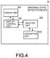
- Fig. 4 is a block diagram illustrating functions of an abnormal state detection device according to a first embodiment.
- the abnormal state detection device 10 includes a display unit 101, a display control unit 102, an acquisition unit 103, and an analysis unit 104.
- the acquisition unit 103 acquires an image of a device (not shown) of which an abnormal state is desired to be detected.
- the acquisition unit 103 outputs the acquired image to the analysis unit 104.
- the analysis unit 104 determines an abnormal state of the device based on the acquired image.
- the analysis unit 104 generates auxiliary information indicating details or the like of the abnormal state based on the determination results and outputs the auxiliary information to the display control unit 102.
- the display control unit 102 outputs auxiliary information to be superimposed on an image of the device displayed on the display unit 101.
- an abnormal state can be determined based on a captured image.
- the auxiliary information can be generated based on results of determining an abnormal state, and the auxiliary information including the abnormal state can be displayed.
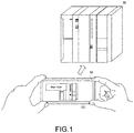
- Fig. 1 is a diagram showing an outline of the abnormal state detection device according to the first embodiment of the present invention.
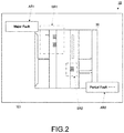
- Fig. 2 is an enlarged view of a display screen of the abnormal state detection device according to the first embodiment of the present invention.
- Fig. 3 is an image diagram showing a procedure in which the abnormal state detection device according to the first embodiment of the present invention detects an abnormal state.
- Fig. 4 is a block diagram of the abnormal state detection device according to the first embodiment of the present invention, as described above.
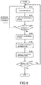
- Fig. 5 is a flowchart for displaying auxiliary information in the abnormal state detection device according to the first embodiment of the present invention.
- an image of the device 30 is acquired by the acquisition unit (a camera) 103 included in the abnormal state detection device 10.
- the entire image of the device 30 is displayed on the display unit 101 of the abnormal state detection device 10.
- the abnormal state detection device 10 may be, for example, any electronic device having an imaging (camera) function such as a smartphone and a tablet.
- the device 30 has state display regions SR1 and SR2 using light emitting diodes (LEDs).
- auxiliary information display regions AR1 and AR2 are set on the display unit 101 as shown in Fig. 2 , the auxiliary information display region AR1 corresponding to a region for displaying auxiliary information on the state display region SR1.
- the auxiliary information display region AR2 corresponds to a region for displaying auxiliary information on the state display region SR2.
- the state display regions SR1 and SR2 can be identified by using a known image recognition technique for an image of the device 30.
- the auxiliary information is displayed in the auxiliary information display region AR1 when the LEDs in the state display region SR1 indicate an abnormal state.
- the auxiliary information is displayed in the auxiliary information display region AR2 when the LEDs in the state display region SR2 indicate an abnormal state.
- a flow of displaying auxiliary information in the auxiliary information display region AR1 is shown, and in Steps 1, 2, and 5, the LEDs 300 emit light to indicate an abnormal state.
- the LEDs 300 are not emitting light.
- the LEDs 300 are emitting red light.
- Steps 3 and 4 are omitted
- the analysis unit 104 determines that an abnormal state has occurred based on the image of Step 5.
- the analysis unit 104 generates auxiliary information.
- the analysis unit 104 transmits the auxiliary information to the display control unit 102.
- the display control unit 102 superimposes the auxiliary information on the captured image of the device 30 of the display unit 101 and displays the auxiliary information in the auxiliary information display region AR1.
- auxiliary information may be, for example, a word indicating an abnormal state, a description regarding the details of the abnormal state, and wording indicating a solution for eliminating the abnormal state. Also, information obtained by combining an abnormal state with explanation means may be used as the auxiliary information.
- the auxiliary information display region AR1 may be scrolled, or the solution may be displayed in a separated manner (the solution is made stepwise) so that an abnormal state can be eliminated step by step.
- an augmented reality (AR) technology that is a technology for augmenting reality may be used.
- AR augmented reality
- a type of an abnormal state and a handling method therefor are displayed to be superimposed in the vicinity of a position of the LEDs 300 of the device 30 that is determined to be in an abnormal state.
- a marker-less type vision-based AR technology may be used.
- the auxiliary information display region AR1 is superimposed near a position where the LEDs 300 emit light.
- the acquisition unit 103 acquires images continuously to include the LEDs of the device (not shown) of which an abnormal state is desired to be detected in the images or acquires a video thereof.
- the abnormal state detection device 10 includes the display unit 101, the display control unit 102, the acquisition unit 103, and the analysis unit 104.
- the acquisition unit 103 outputs the acquired images to the analysis unit 104. By outputting the continuously acquired images, analysis accuracy can be further improved.
- the analysis unit 104 analyzes the light emission pattern of the LEDs from the plurality of acquired images.
- a specific analysis method of the light emission pattern of the LEDs using the images for example, there is a method of comparing brightnesses of the LEDs of the plurality of images. By acquiring a change in luminance of the same LED, the light emission pattern of the LEDs can be determined.
- a method of analyzing the light emission pattern of the LEDs using a video may be, for example, a method of defining frame rates of the video and acquiring a change in luminance of the same LED for each frame rate. This makes it possible to determine the light emission pattern of the LEDs.
- the light emission pattern of the LEDs is associated with abnormal states. Therefore, the analysis unit 104 can detect an abnormal state from the light emission pattern.
- an abnormal state can be determined by the same processing, and auxiliary information when two or more LEDs are combined can be obtained.
- the analysis unit 104 outputs the auxiliary information to the display control unit 102 using AR technology.
- the display control unit 102 outputs the auxiliary information to the display unit 101.
- the display unit 101 superimposes the captured image of the device and displays the auxiliary information.
- the acquisition unit 103 acquires an image or a video (S101).
- the analysis unit 104 receives the image or the video from the acquisition unit 103 and analyzes an abnormal state (S102). The analysis unit 104 determines whether or not the number of times in which an abnormal state is able to be determined (the designated number of times: n) has been reached (S103). If the number of times is within the designated number (S103: Yes), the steps of acquiring the image (S101) and analyzing an abnormal state (S102) are repeated to acquire the abnormal state (S104).
- the analysis unit 104 acquires the auxiliary information from the storage unit 105 (S105).
- the analysis unit 104 outputs the auxiliary information to the display control unit 102.
- the display control unit 102 displays the auxiliary information on the display unit 101 (S106).
- the analysis unit 104 determines whether reanalysis is necessary (S107) or not. If there has not been complete recovery from an abnormal state due to a change of the abnormal state, reanalysis is determined to be required (S107: Yes) and the acquisition unit 103 acquires an image or a video again (S101).
- step (S107) of determining whether reanalysis is necessary or not when it is determined that recovery from an abnormal state is not possible even if reanalysis were continued, the flow may be terminated.
- the analysis unit 104 may end the flow.
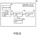
- Fig. 6 is a block diagram of the abnormal state detection device according to the second embodiment of the present invention.
- Fig. 7 is a flowchart for registering and displaying auxiliary information in the abnormal state detection device according to the second embodiment of the present invention.
- an abnormal state detection device 10A includes the display unit 101, the display control unit 102, the acquisition unit 103, the analysis unit 104, and a storage unit 105.
- the abnormal state detection device 10A according to the second embodiment is different from the abnormal state detection device 10 according to the first embodiment in that the storage unit 105 is provided and a function of registering auxiliary information is provided.
- the other configuration of the abnormal state detection device 10A is the same as that of the abnormal state detection device 10, and the description of the same parts will be omitted.
- the storage unit 105 associates a light emission pattern, an abnormal state, and auxiliary information with each other and stores them.
- the analysis unit 104 makes an inquiry to the storage unit 105 as necessary.
- the analysis unit 104 acquires the auxiliary information registered in the storage unit 105 based on the light emission pattern.
- the acquisition unit 103 acquires an image or a video (S201).
- the analysis unit 104 receives the image or the video from the acquisition unit 103 and analyzes an abnormal state (S202). The analysis unit 104 determines whether or not the number of times is a number (the designated number of times: n) in which an abnormal state is able to be analyzed (S203). If the number of times is within the designated number (S203: Yes), the steps of acquiring the image (S201) and analyzing an abnormal state (S202) are repeated to identify an abnormal state (S204).
- the analysis unit 104 determines whether or not auxiliary information can be obtained from the storage unit 105 (S205). If the auxiliary information cannot be obtained (S205: No), the analysis unit 104 determines whether to register the abnormal state (S206) that is occurring. When the abnormal state is registered (S206: Yes), the analysis unit 104 associates the image (or video) acquired by the acquisition unit 103 with the auxiliary information associated with the image or video and registers them (S207). Whether an abnormal state can be registered or not can be selected by an operation input unit (not shown).
- the analysis unit 104 outputs the auxiliary information to the display control unit 102, and the display control unit 102 displays the auxiliary information on the display unit 101 (S208).
- the analysis unit 104 outputs the auxiliary information to the display control unit 102, and the display control unit 102 displays the auxiliary information on the display unit 101 (S208).
- the analysis unit 104 may display the auxiliary information for itself based on the light emission pattern of the LEDs.
- the input when registering the auxiliary information may be performed by using a software keyboard or the like of the abnormal state detection device 10A.
- Fig. 8 is a block diagram of the abnormal state detection device according to the third embodiment of the present invention.
- an abnormal state detection device 10B according to the third embodiment is different from the abnormal state detection device 10 according to the first embodiment in that a storage unit 105 and a communication unit 106 are provided.
- the other configuration of the abnormal state detection device 10B is the same as that of the abnormal state detection device 10, and the description of the same parts will be omitted.
- the abnormal state detection device 10B includes the display unit 101, the display control unit 102, the acquisition unit 103, the analysis unit 104, the storage unit 105, and the communication unit 106.
- the acquisition unit 103 outputs an acquired image to the analysis unit 104.
- the analysis unit 104 analyzes a light emission pattern of the LEDs in the plurality of acquired image.
- the analysis unit 104 transmits the light emission pattern of the LEDs to the communication unit 106.
- the communication unit 106 transmits data to an external device having an abnormal state storage unit (not shown).
- the communication unit 106 receives an abnormal state and an analysis method from the light emission pattern of the LEDs from the external device.
- the communication unit 106 outputs the abnormal state and a solution to the analysis unit 104.
- the analysis unit 104 generates auxiliary information based on the acquired abnormal state and the analysis method.
- the display unit 101 can display the auxiliary information by superimposing it on a captured image of the device.
- the communication unit 106 described above communicates with the external device.
- the abnormal state may be obtained by using a general-purpose network such as the Internet or a cloud for the light emission pattern of the LEDs.
Landscapes
- Engineering & Computer Science (AREA)
- Theoretical Computer Science (AREA)
- General Physics & Mathematics (AREA)
- Physics & Mathematics (AREA)
- Quality & Reliability (AREA)
- General Engineering & Computer Science (AREA)
- Computer Vision & Pattern Recognition (AREA)
- Microelectronics & Electronic Packaging (AREA)
- Signal Processing (AREA)
- Multimedia (AREA)
- Alarm Systems (AREA)
- Debugging And Monitoring (AREA)
- Closed-Circuit Television Systems (AREA)
- Studio Devices (AREA)
- Investigating Materials By The Use Of Optical Means Adapted For Particular Applications (AREA)
Abstract
Description
- The present invention relates to a technique for displaying an abnormal state of a device.
- A device disclosed in
Patent Literature 1 images an appearance of a detection target device using a monitoring camera and receives information for identifying a state of the device using a dedicated communication means. When an abnormality occurs in the device, it superimposes and displays information for identifying an abnormal state on an image of the device. - [Patent Literature 1]
Japanese Patent Application Laid-Open No.2012-018605 - However, in a case of using the technique disclosed in
Patent Literature 1, it is required to receive the state of the device using a dedicated communication means. In addition, in order to secure the communication means, a device therefor, a place for installing the device, and construction and maintenance of the device are required, which is not convenient. - Therefore, an object of the present invention is to allow an abnormal state to be confirmed easily while minimizing constituents of a device for identifying an abnormal state of a device.
- This abnormal state detection device includes an acquisition unit that acquires an image imaging a device that performs an output of an abnormal state using a light emitting diode (LED), an analysis unit that analyzes the abnormal state of the device based on a light emission pattern of the LED in the image, and generates auxiliary information indicating the abnormal state based on an analysis result, and a display control unit that outputs the auxiliary information to a display unit.
- With this configuration, the abnormal state of the device can be analyzed from the image of the light emission pattern of the LED due to a type of abnormality of the device being associated with a light emission pattern of the LED. Based on the analysis result, the abnormal state of the device or the auxiliary information for eliminating the abnormal state can be generated and displayed.
- The display control unit of the abnormal state detection device may superimpose and display the auxiliary information over a part of the image.
- With this configuration, since a lighting state of the device and the auxiliary information can be displayed on the same screen, good visibility is provided.
- The analysis unit of the abnormal state detection device may generate the auxiliary information based on results in which analysis is performed using a plurality of images obtained by continuously capturing images of the device.
- With this configuration, since a blinking pattern or the like can be analyzed, various pieces of detailed auxiliary information can be displayed.
- The analysis unit of the abnormal state detection device may analyze the abnormal state from a plurality of locations in the image.
- With this configuration, even when a detection target device has a plurality of LEDs or a plurality of devices are displayed, the abnormal state can be analyzed for each.
- The abnormal state detection device may associate the image, the abnormal state, and the auxiliary information with each other and store them, and the analysis unit may obtain the auxiliary information based on the image or the abnormal state stored in a storage unit.
- With this configuration, since a plurality of pieces of information are associated with each other, it is possible to efficiently search for the auxiliary information.
- The analysis unit of the abnormal state detection device may associate the auxiliary information with the abnormal state and the image and store the auxiliary information.
- With this configuration, even when auxiliary information does not exist, the abnormal state and the image can be stored in association with each other. Thus, this can be used for the next analysis.
- The analysis unit of the abnormal state detection device may change the auxiliary information in accordance with a change of the abnormal state.
- With this configuration, even when required auxiliary information changes due to a change of an abnormal state, appropriate auxiliary information can be obtained. Thus, an abnormal state can be smoothly resolved.
- The communication unit of the abnormal state detection device may receive the auxiliary information by transmitting the image or the analysis results.
- With this configuration, in an external device (apparatus), the auxiliary information can be obtained by analyzing the image, or the auxiliary information can be obtained from the analysis result, and thus constituents of the abnormal state detection device can be minimized.
- According to the present invention, constituents of a device for identifying an abnormal state of a device can be minimized, and a user can easily check the abnormal state of the device.
-
-
Fig. 1 is a diagram showing an outline of an abnormal state detection device according to a first embodiment of the present invention. -
Fig. 2 is an enlarged view of a display of the abnormal state detection device according to the first embodiment of the present invention. -
Fig. 3 is an image diagram showing a procedure in which the abnormal state detection device according to the first embodiment of the present invention detects an abnormal state. -
Fig. 4 is a block diagram of the abnormal state detection device according to the first embodiment of the present invention. -
Fig. 5 is a flowchart for displaying auxiliary information in the abnormal state detection device according to the first embodiment of the present invention. -
Fig. 6 is a block diagram of an abnormal state detection device according to a second embodiment of the present invention. -
Fig. 7 is a flowchart for registering and displaying auxiliary information in the abnormal state detection device according to the second embodiment of the present invention. -
Fig. 8 is a block diagram of an abnormal state detection device according to a third embodiment of the present invention. - First, an example adopting the present invention will be described with reference to
Fig. 4. Fig. 4 is a block diagram illustrating functions of an abnormal state detection device according to a first embodiment. - As shown in
Fig. 4 , the abnormalstate detection device 10 includes adisplay unit 101, adisplay control unit 102, anacquisition unit 103, and ananalysis unit 104. - The
acquisition unit 103 acquires an image of a device (not shown) of which an abnormal state is desired to be detected. Theacquisition unit 103 outputs the acquired image to theanalysis unit 104. Theanalysis unit 104 determines an abnormal state of the device based on the acquired image. Theanalysis unit 104 generates auxiliary information indicating details or the like of the abnormal state based on the determination results and outputs the auxiliary information to thedisplay control unit 102. Thedisplay control unit 102 outputs auxiliary information to be superimposed on an image of the device displayed on thedisplay unit 101. - Thus, an abnormal state can be determined based on a captured image. In addition, the auxiliary information can be generated based on results of determining an abnormal state, and the auxiliary information including the abnormal state can be displayed.
-
Fig. 1 is a diagram showing an outline of the abnormal state detection device according to the first embodiment of the present invention.Fig. 2 is an enlarged view of a display screen of the abnormal state detection device according to the first embodiment of the present invention.Fig. 3 is an image diagram showing a procedure in which the abnormal state detection device according to the first embodiment of the present invention detects an abnormal state.Fig. 4 is a block diagram of the abnormal state detection device according to the first embodiment of the present invention, as described above.Fig. 5 is a flowchart for displaying auxiliary information in the abnormal state detection device according to the first embodiment of the present invention. - First, an outline of the abnormal state detection device according to the first embodiment will be described with reference to
Figs. 1 and2 . - In the example shown in
Fig. 1 , an image of thedevice 30 is acquired by the acquisition unit (a camera) 103 included in the abnormalstate detection device 10. The entire image of thedevice 30 is displayed on thedisplay unit 101 of the abnormalstate detection device 10. The abnormalstate detection device 10 may be, for example, any electronic device having an imaging (camera) function such as a smartphone and a tablet. - As shown in
Fig. 2 , thedevice 30 has state display regions SR1 and SR2 using light emitting diodes (LEDs). In addition, auxiliary information display regions AR1 and AR2 are set on thedisplay unit 101 as shown inFig. 2 , the auxiliary information display region AR1 corresponding to a region for displaying auxiliary information on the state display region SR1. Similarly, the auxiliary information display region AR2 corresponds to a region for displaying auxiliary information on the state display region SR2. - The state display regions SR1 and SR2 can be identified by using a known image recognition technique for an image of the
device 30. - The auxiliary information is displayed in the auxiliary information display region AR1 when the LEDs in the state display region SR1 indicate an abnormal state. Similarly, the auxiliary information is displayed in the auxiliary information display region AR2 when the LEDs in the state display region SR2 indicate an abnormal state.
- Although an example in which an entire image of the
device 30 is captured has been described in the present embodiment, it is sufficient if at least a region such as the state display regions SR1 and SR2 that can indicate an abnormal state using the LEDs or the like is captured, as described above. - In the example shown in
Fig. 3 , a flow of displaying auxiliary information in the auxiliary information display region AR1 is shown, and inSteps LEDs 300 emit light to indicate an abnormal state. - In an image of
Step 1 acquired by the acquisition unit (camera) 103, theLEDs 300 are not emitting light. - In an image of
Step 2 acquired by the acquisition unit (camera) 103, theLEDs 300 are emitting red light. - If the
LEDs 300 continuously emit red light fromStep 2 to Step 5 (Steps 3 and 4 are omitted), theanalysis unit 104 determines that an abnormal state has occurred based on the image ofStep 5. - Next, the
analysis unit 104 generates auxiliary information. Theanalysis unit 104 transmits the auxiliary information to thedisplay control unit 102. - The
display control unit 102 superimposes the auxiliary information on the captured image of thedevice 30 of thedisplay unit 101 and displays the auxiliary information in the auxiliary information display region AR1. - Further, the auxiliary information may be, for example, a word indicating an abnormal state, a description regarding the details of the abnormal state, and wording indicating a solution for eliminating the abnormal state. Also, information obtained by combining an abnormal state with explanation means may be used as the auxiliary information.
- If the wording has a number of characters that cannot be displayed in the auxiliary information display region AR1, the auxiliary information display region AR1 may be scrolled, or the solution may be displayed in a separated manner (the solution is made stepwise) so that an abnormal state can be eliminated step by step.
- Here, a specific method for displaying the auxiliary information in the auxiliary information display region AR1 will be described.
- In order to configure the auxiliary information display region AR1, for example, an augmented reality (AR) technology that is a technology for augmenting reality may be used. In the present invention, by using AR technology, a type of an abnormal state and a handling method therefor are displayed to be superimposed in the vicinity of a position of the
LEDs 300 of thedevice 30 that is determined to be in an abnormal state. - For example, a marker-less type vision-based AR technology may be used. When the
LEDs 300 are determined to be in an abnormal state by analyzing a light emission pattern of theLEDs 300, the auxiliary information display region AR1 is superimposed near a position where theLEDs 300 emit light. - Next, a flow of the specific processing will be described with reference to
Figs. 4 and5 . As described above, theacquisition unit 103 acquires images continuously to include the LEDs of the device (not shown) of which an abnormal state is desired to be detected in the images or acquires a video thereof. - As described above, the abnormal
state detection device 10 includes thedisplay unit 101, thedisplay control unit 102, theacquisition unit 103, and theanalysis unit 104. - The
acquisition unit 103 outputs the acquired images to theanalysis unit 104. By outputting the continuously acquired images, analysis accuracy can be further improved. - The
analysis unit 104 analyzes the light emission pattern of the LEDs from the plurality of acquired images. As a specific analysis method of the light emission pattern of the LEDs using the images, for example, there is a method of comparing brightnesses of the LEDs of the plurality of images. By acquiring a change in luminance of the same LED, the light emission pattern of the LEDs can be determined. Further, a method of analyzing the light emission pattern of the LEDs using a video may be, for example, a method of defining frame rates of the video and acquiring a change in luminance of the same LED for each frame rate. This makes it possible to determine the light emission pattern of the LEDs. - The light emission pattern of the LEDs is associated with abnormal states. Therefore, the
analysis unit 104 can detect an abnormal state from the light emission pattern. - In addition, even when a plurality of LEDs are present, an abnormal state can be determined by the same processing, and auxiliary information when two or more LEDs are combined can be obtained.
- The
analysis unit 104 outputs the auxiliary information to thedisplay control unit 102 using AR technology. Thedisplay control unit 102 outputs the auxiliary information to thedisplay unit 101. Thedisplay unit 101 superimposes the captured image of the device and displays the auxiliary information. - A flow of processing will be described with reference to the flowchart of
Fig. 5 . - The
acquisition unit 103 acquires an image or a video (S101). - The
analysis unit 104 receives the image or the video from theacquisition unit 103 and analyzes an abnormal state (S102). Theanalysis unit 104 determines whether or not the number of times in which an abnormal state is able to be determined (the designated number of times: n) has been reached (S103). If the number of times is within the designated number (S103: Yes), the steps of acquiring the image (S101) and analyzing an abnormal state (S102) are repeated to acquire the abnormal state (S104). - The
analysis unit 104 acquires the auxiliary information from the storage unit 105 (S105). Theanalysis unit 104 outputs the auxiliary information to thedisplay control unit 102. Thedisplay control unit 102 displays the auxiliary information on the display unit 101 (S106). - The
analysis unit 104 determines whether reanalysis is necessary (S107) or not. If there has not been complete recovery from an abnormal state due to a change of the abnormal state, reanalysis is determined to be required (S107: Yes) and theacquisition unit 103 acquires an image or a video again (S101). - When the
analysis unit 104 determines that an abnormal state has transitioned to a normal state and that reanalysis is unnecessary (S107: No), the processing ends. - Also, in the step (S107) of determining whether reanalysis is necessary or not, when it is determined that recovery from an abnormal state is not possible even if reanalysis were continued, the flow may be terminated.
- Further, when the number of times exceeds the designated number (S103: No), repetition of the steps is terminated, the step of acquiring the abnormal state (S104) is executed, and the subsequent steps are executed.
- Also, when an abnormal state cannot be identified (S102), the
analysis unit 104 may end the flow. - Next, an outline of an abnormal state detection device according to a second embodiment will be described with reference to
Figs. 6 and7 .Fig. 6 is a block diagram of the abnormal state detection device according to the second embodiment of the present invention.Fig. 7 is a flowchart for registering and displaying auxiliary information in the abnormal state detection device according to the second embodiment of the present invention. - As shown in
Fig. 6 , an abnormalstate detection device 10A includes thedisplay unit 101, thedisplay control unit 102, theacquisition unit 103, theanalysis unit 104, and astorage unit 105. The abnormalstate detection device 10A according to the second embodiment is different from the abnormalstate detection device 10 according to the first embodiment in that thestorage unit 105 is provided and a function of registering auxiliary information is provided. The other configuration of the abnormalstate detection device 10A is the same as that of the abnormalstate detection device 10, and the description of the same parts will be omitted. - As shown in
Figs. 6 and7 , thestorage unit 105 associates a light emission pattern, an abnormal state, and auxiliary information with each other and stores them. Theanalysis unit 104 makes an inquiry to thestorage unit 105 as necessary. Theanalysis unit 104 acquires the auxiliary information registered in thestorage unit 105 based on the light emission pattern. - The
acquisition unit 103 acquires an image or a video (S201). - The
analysis unit 104 receives the image or the video from theacquisition unit 103 and analyzes an abnormal state (S202). Theanalysis unit 104 determines whether or not the number of times is a number (the designated number of times: n) in which an abnormal state is able to be analyzed (S203). If the number of times is within the designated number (S203: Yes), the steps of acquiring the image (S201) and analyzing an abnormal state (S202) are repeated to identify an abnormal state (S204). - The
analysis unit 104 determines whether or not auxiliary information can be obtained from the storage unit 105 (S205). If the auxiliary information cannot be obtained (S205: No), theanalysis unit 104 determines whether to register the abnormal state (S206) that is occurring. When the abnormal state is registered (S206: Yes), theanalysis unit 104 associates the image (or video) acquired by theacquisition unit 103 with the auxiliary information associated with the image or video and registers them (S207). Whether an abnormal state can be registered or not can be selected by an operation input unit (not shown). - The
analysis unit 104 outputs the auxiliary information to thedisplay control unit 102, and thedisplay control unit 102 displays the auxiliary information on the display unit 101 (S208). - Further, when the designated number of times has been exceeded (S203: No), repetition of the steps is terminated, the step of identifying an abnormal state (S204) is executed, and the subsequent steps are executed.
- If the auxiliary information can be obtained (S205: Yes), the
analysis unit 104 outputs the auxiliary information to thedisplay control unit 102, and thedisplay control unit 102 displays the auxiliary information on the display unit 101 (S208). - If the auxiliary information is not registered (S206: No), the
analysis unit 104 ends the flow. - Also, it is not necessary to make an inquiry to the
storage unit 105 for all light emission patterns of the LEDs, and theanalysis unit 104 may display the auxiliary information for itself based on the light emission pattern of the LEDs. - Also, the input when registering the auxiliary information may be performed by using a software keyboard or the like of the abnormal
state detection device 10A. - Next, an outline of an abnormal state detection device according to a third embodiment will be described with reference to
Fig. 8. Fig. 8 is a block diagram of the abnormal state detection device according to the third embodiment of the present invention. - As shown in
Fig. 8 , an abnormalstate detection device 10B according to the third embodiment is different from the abnormalstate detection device 10 according to the first embodiment in that astorage unit 105 and acommunication unit 106 are provided. The other configuration of the abnormalstate detection device 10B is the same as that of the abnormalstate detection device 10, and the description of the same parts will be omitted. - The abnormal
state detection device 10B includes thedisplay unit 101, thedisplay control unit 102, theacquisition unit 103, theanalysis unit 104, thestorage unit 105, and thecommunication unit 106. - The
acquisition unit 103 outputs an acquired image to theanalysis unit 104. - The
analysis unit 104 analyzes a light emission pattern of the LEDs in the plurality of acquired image. Theanalysis unit 104 transmits the light emission pattern of the LEDs to thecommunication unit 106. Thecommunication unit 106 transmits data to an external device having an abnormal state storage unit (not shown). Thecommunication unit 106 receives an abnormal state and an analysis method from the light emission pattern of the LEDs from the external device. - The
communication unit 106 outputs the abnormal state and a solution to theanalysis unit 104. Theanalysis unit 104 generates auxiliary information based on the acquired abnormal state and the analysis method. - Also by using this method, the
display unit 101 can display the auxiliary information by superimposing it on a captured image of the device. - Further, the
communication unit 106 described above communicates with the external device. However, the abnormal state may be obtained by using a general-purpose network such as the Internet or a cloud for the light emission pattern of the LEDs. -
- AR1, AR2
- Auxiliary information display region
- SR1, SR2
- State display region
- 10, 10A, 10B
- Abnormal state detection device
- 30
- Device
- 101
- Display unit
- 102
- Display control unit
- 103
- Acquisition unit
- 104
- Analysis unit
- 105
- Storage unit
- 106
- Communication unit
- 300
- LED
Claims (10)
- An abnormal state detection device comprising:an acquisition unit which acquires an image imaging a device that performs an output of an abnormal state using an LED;an analysis unit which analyzes the abnormal state of the device based on a light emission pattern of the LED in the image, and generates auxiliary information indicating the abnormal state based on an analysis result; anda display control unit which outputs the auxiliary information to a display unit.
- The abnormal state detection device according to claim 1, wherein the display control unit superimposes and displays the auxiliary information over a part of the image.
- The abnormal state detection device according to claim 1 or 2, wherein the analysis unit generates the auxiliary information based on the analysis result obtained by performing analysis using a plurality of images obtained by continuously imaging the device.
- The abnormal state detection device according to any one of claims 1 to 3, wherein the analysis unit analyzes a plurality of abnormal states from the image.
- The abnormal state detection device according to any one of claims 1 to 4, further comprising a storage unit which associates the image, the abnormal state, and the auxiliary information with each other and stores them,
wherein the analysis unit obtains the auxiliary information based on the image or the abnormal state stored in the storage unit. - The abnormal state detection device according to claim 5, wherein the analysis unit associates the abnormal state, the image, and the auxiliary information with each other and causes the storage unit to store them.
- The abnormal state detection device according to any one of claims 1 to 6, wherein the analysis unit changes the auxiliary information in accordance with a change of the abnormal state.
- The abnormal state detection device according to any one of claims 1 to 7, further comprising a communication unit that transmits the image or the analysis result and receives the auxiliary information.
- An abnormal state detection method using an abnormal state detection device which executes steps of:acquiring an image of a device in an abnormal state;analyzing the abnormal state of the device from the image and generating auxiliary information indicating the abnormal state based on an analysis result; andoutputting the auxiliary information to a display unit.
- An abnormal state detection program which causes a computer to execute processes of:acquiring an image of a device in an abnormal state;analyzing the abnormal state of the device from the image and generating auxiliary information indicating the abnormal state based on an analysis result; andoutputting the auxiliary information to a display unit.
Applications Claiming Priority (2)
| Application Number | Priority Date | Filing Date | Title |
|---|---|---|---|
| JP2017216985A JP6904223B2 (en) | 2017-11-10 | 2017-11-10 | Abnormal state detection device, abnormal state detection method, and abnormal state detection program |
| PCT/JP2018/040054 WO2019093171A1 (en) | 2017-11-10 | 2018-10-29 | Abnormal state detection device, abnormal state detection method, and abnormal state detection program |
Publications (2)
| Publication Number | Publication Date |
|---|---|
| EP3709170A1 true EP3709170A1 (en) | 2020-09-16 |
| EP3709170A4 EP3709170A4 (en) | 2021-07-21 |
Family
ID=66437738
Family Applications (1)
| Application Number | Title | Priority Date | Filing Date |
|---|---|---|---|
| EP18877183.6A Pending EP3709170A4 (en) | 2017-11-10 | 2018-10-29 | Abnormal state detection device, abnormal state detection method, and abnormal state detection program |
Country Status (5)
| Country | Link |
|---|---|
| US (1) | US11574399B2 (en) |
| EP (1) | EP3709170A4 (en) |
| JP (1) | JP6904223B2 (en) |
| CN (1) | CN111033472B (en) |
| WO (1) | WO2019093171A1 (en) |
Families Citing this family (7)
| Publication number | Priority date | Publication date | Assignee | Title |
|---|---|---|---|---|
| JP2021125859A (en) * | 2020-02-10 | 2021-08-30 | カシオ計算機株式会社 | Display output control device, display output control system, display output control method and program |
| US20230011330A1 (en) * | 2021-07-09 | 2023-01-12 | At&T Intellectual Property I, L.P. | Device condition determination |
| US12183077B2 (en) * | 2022-08-17 | 2024-12-31 | Honeywell International Inc. | System gateway analysis |
| JP7809626B2 (en) * | 2022-11-07 | 2026-02-02 | キヤノン株式会社 | Information processing device, information processing method, and computer program |
| CN116596267B (en) * | 2023-05-31 | 2023-11-21 | 上海秦望环保材料有限公司 | Comprehensive treatment management system for garbage incinerator slag |
| CN116416249B (en) * | 2023-06-08 | 2023-09-05 | 张家港市民华塑胶有限公司 | Quality detection and evaluation method and system for artificial sports grass filaments |
| CN118587636B (en) * | 2024-08-05 | 2024-10-29 | 中国交通信息科技集团有限公司杭州分公司 | Anomaly detection method, device, equipment and medium |
Family Cites Families (27)
| Publication number | Priority date | Publication date | Assignee | Title |
|---|---|---|---|---|
| US4460969A (en) * | 1980-12-04 | 1984-07-17 | The United States Of America As Represented By The Secretary Of The Army | Image spectrum analyzer for cartographic feature extraction |
| US6677565B1 (en) * | 1998-08-18 | 2004-01-13 | Veeco Tucson Inc. | High speed autofocus and tilt for an optical imaging system |
| US6133844A (en) * | 1998-12-21 | 2000-10-17 | Lexmark International, Inc. | System and method for programming an operator panel LED for printer |
| US8570378B2 (en) * | 2002-07-27 | 2013-10-29 | Sony Computer Entertainment Inc. | Method and apparatus for tracking three-dimensional movements of an object using a depth sensing camera |
| US9174119B2 (en) * | 2002-07-27 | 2015-11-03 | Sony Computer Entertainement America, LLC | Controller for providing inputs to control execution of a program when inputs are combined |
| JP2005242916A (en) * | 2004-02-27 | 2005-09-08 | Japan Network Storage Laboratory Inc | Rack for computer equipment |
| JP2006039963A (en) * | 2004-07-27 | 2006-02-09 | Brother Ind Ltd | Error handling information display program and image forming system |
| US8427426B2 (en) * | 2005-05-27 | 2013-04-23 | Sony Computer Entertainment Inc. | Remote input device |
| JP4234715B2 (en) * | 2005-12-13 | 2009-03-04 | シャープ株式会社 | Electronic equipment operation system |
| USRE48417E1 (en) * | 2006-09-28 | 2021-02-02 | Sony Interactive Entertainment Inc. | Object direction using video input combined with tilt angle information |
| US8325710B2 (en) * | 2007-08-09 | 2012-12-04 | Phybridge Inc. | Inline power system and method for network communications |
| CN102291869B (en) * | 2010-06-21 | 2014-03-26 | 鸿富锦精密工业(深圳)有限公司 | Light emitting diode (LED) control system and method |
| JP5349417B2 (en) * | 2010-07-09 | 2013-11-20 | 株式会社日立システムズ | Maintenance and monitoring system using augmented reality technology |
| US8738754B2 (en) * | 2011-04-07 | 2014-05-27 | International Business Machines Corporation | Systems and methods for managing computing systems utilizing augmented reality |
| JP5509158B2 (en) * | 2011-07-28 | 2014-06-04 | 京セラドキュメントソリューションズ株式会社 | Image forming system, image forming apparatus, portable terminal |
| JP5914385B2 (en) * | 2012-05-09 | 2016-05-11 | 太平洋工業株式会社 | Server monitoring apparatus and server monitoring system |
| JP2014010529A (en) * | 2012-06-28 | 2014-01-20 | Hitachi Systems Ltd | Incident management operation system, method for automatically creating failure determination condition for incident management operation system, and method for automatically transmitting failure countermeasure procedure addition request for incident management operation system |
| JP2015039095A (en) * | 2012-07-31 | 2015-02-26 | 株式会社東芝 | Electronic device, method and program |
| US8867819B2 (en) * | 2013-01-28 | 2014-10-21 | International Business Machines Corporation | Information technology asset location using visual detectors |
| JP6065640B2 (en) * | 2013-02-21 | 2017-01-25 | ブラザー工業株式会社 | Computer program and control device |
| EP2784681A1 (en) | 2013-03-27 | 2014-10-01 | British Telecommunications public limited company | Visual diagnosis tool |
| WO2015068275A1 (en) * | 2013-11-08 | 2015-05-14 | 株式会社日立製作所 | Monitoring system and monitoring method |
| JP2015130052A (en) * | 2014-01-07 | 2015-07-16 | 株式会社日立システムズ | Rack and equipment automatic monitoring system, automatic failure notification method, and automatic failure notification program |
| JP2016006595A (en) * | 2014-06-20 | 2016-01-14 | 日本電気通信システム株式会社 | State monitoring system and state monitoring method |
| WO2016131022A1 (en) * | 2015-02-12 | 2016-08-18 | Glowforge Inc. | Cloud controlled laser fabrication |
| JP2019203691A (en) * | 2016-11-11 | 2019-11-28 | オムロン株式会社 | Lighting device |
| US10209202B1 (en) * | 2017-06-14 | 2019-02-19 | Facebook Technologies, Llc | Optical characterization system for wide field of view diffractive optical elements |
-
2017
- 2017-11-10 JP JP2017216985A patent/JP6904223B2/en active Active
-
2018
- 2018-10-29 CN CN201880052822.0A patent/CN111033472B/en active Active
- 2018-10-29 US US16/639,737 patent/US11574399B2/en active Active
- 2018-10-29 EP EP18877183.6A patent/EP3709170A4/en active Pending
- 2018-10-29 WO PCT/JP2018/040054 patent/WO2019093171A1/en not_active Ceased
Also Published As
| Publication number | Publication date |
|---|---|
| EP3709170A4 (en) | 2021-07-21 |
| US20210125321A1 (en) | 2021-04-29 |
| CN111033472A (en) | 2020-04-17 |
| JP6904223B2 (en) | 2021-07-14 |
| US11574399B2 (en) | 2023-02-07 |
| CN111033472B (en) | 2023-11-28 |
| JP2019087178A (en) | 2019-06-06 |
| WO2019093171A1 (en) | 2019-05-16 |
Similar Documents
| Publication | Publication Date | Title |
|---|---|---|
| US11574399B2 (en) | Abnormal state detection device, abnormal state detection method, and recording medium | |
| US11798193B2 (en) | Multi-dimensional image detection on at least two acquired images | |
| EP3270134A1 (en) | Gas leak location estimating device, gas leak location estimating system, gas leak location estimating method and gas leak location estimating program | |
| US20170278057A1 (en) | Information processing apparatus, shelf label management system, control method, and program | |
| US9113152B2 (en) | Frame block comparison | |
| US20180027218A1 (en) | Work assistance device, work assistance system, work assistance method, and recording medium storing work assistance program | |
| JP2015165400A (en) | Method for product recognition from multiple images | |
| US20230026038A1 (en) | Image processing apparatus, image processing method, and storage medium | |
| US20110304636A1 (en) | Wallpaper image generation method and portable electric device thereof | |
| US11527067B2 (en) | Electronic device, action instance generation method, and recording medium | |
| US20190164281A1 (en) | Robotic pill filling, counting, and validation | |
| US11113531B2 (en) | Annotation device, annotation method, and non-transitory computer-readable storage medium | |
| CN113447128A (en) | Multi-person body temperature detection method and device, electronic equipment and storage medium | |
| WO2017169907A1 (en) | Work assistance device, work assistance method, and recording medium | |
| KR101576445B1 (en) | image evalution automation method and apparatus using video signal | |
| US9934593B2 (en) | Status determination system | |
| JP2019021318A (en) | Telepresence framework for marking region of interest using head-mounted devices | |
| US10489921B2 (en) | Behavior analysis apparatus and behavior analysis method | |
| US11302010B2 (en) | Gas-detection image processing device, gas-detection image processing method, and gas-detection image processing program | |
| US20110304467A1 (en) | Image monitoring device and method | |
| JP2017224229A (en) | Facility monitoring portable terminal and facility monitoring system | |
| CN115766797A (en) | Micromodule temperature visualization method, device, handheld terminal and temperature inspection method | |
| JPWO2019167278A1 (en) | Store equipment, store systems, image acquisition methods, and programs | |
| CN111258890A (en) | Program test method, storage medium, and system | |
| WO2023180032A1 (en) | Augmented reality-enabled systems and methods for cable identification |
Legal Events
| Date | Code | Title | Description |
|---|---|---|---|
| STAA | Information on the status of an ep patent application or granted ep patent |
Free format text: STATUS: THE INTERNATIONAL PUBLICATION HAS BEEN MADE |
|
| PUAI | Public reference made under article 153(3) epc to a published international application that has entered the european phase |
Free format text: ORIGINAL CODE: 0009012 |
|
| STAA | Information on the status of an ep patent application or granted ep patent |
Free format text: STATUS: REQUEST FOR EXAMINATION WAS MADE |
|
| 17P | Request for examination filed |
Effective date: 20200214 |
|
| AK | Designated contracting states |
Kind code of ref document: A1 Designated state(s): AL AT BE BG CH CY CZ DE DK EE ES FI FR GB GR HR HU IE IS IT LI LT LU LV MC MK MT NL NO PL PT RO RS SE SI SK SM TR |
|
| AX | Request for extension of the european patent |
Extension state: BA ME |
|
| DAV | Request for validation of the european patent (deleted) | ||
| DAX | Request for extension of the european patent (deleted) | ||
| A4 | Supplementary search report drawn up and despatched |
Effective date: 20210622 |
|
| RIC1 | Information provided on ipc code assigned before grant |
Ipc: G06F 11/32 20060101AFI20210616BHEP Ipc: G06F 11/07 20060101ALI20210616BHEP Ipc: H04N 5/232 20060101ALI20210616BHEP Ipc: G03G 15/00 20060101ALI20210616BHEP Ipc: G06T 11/00 20060101ALI20210616BHEP Ipc: G06F 11/30 20060101ALI20210616BHEP Ipc: G06T 7/00 20170101ALI20210616BHEP Ipc: H04N 5/225 20060101ALI20210616BHEP |
|
| STAA | Information on the status of an ep patent application or granted ep patent |
Free format text: STATUS: EXAMINATION IS IN PROGRESS |
|
| 17Q | First examination report despatched |
Effective date: 20230314 |