EP3709147A1 - Method and apparatus for determining fingerprint collection region - Google Patents
Method and apparatus for determining fingerprint collection region Download PDFInfo
- Publication number
- EP3709147A1 EP3709147A1 EP19216905.0A EP19216905A EP3709147A1 EP 3709147 A1 EP3709147 A1 EP 3709147A1 EP 19216905 A EP19216905 A EP 19216905A EP 3709147 A1 EP3709147 A1 EP 3709147A1
- Authority
- EP
- European Patent Office
- Prior art keywords
- change rate
- moment
- contact region
- determining
- fingerprint
- Prior art date
- Legal status (The legal status is an assumption and is not a legal conclusion. Google has not performed a legal analysis and makes no representation as to the accuracy of the status listed.)
- Granted
Links
Images




Classifications
-
- G—PHYSICS
- G06—COMPUTING OR CALCULATING; COUNTING
- G06V—IMAGE OR VIDEO RECOGNITION OR UNDERSTANDING
- G06V40/00—Recognition of biometric, human-related or animal-related patterns in image or video data
- G06V40/10—Human or animal bodies, e.g. vehicle occupants or pedestrians; Body parts, e.g. hands
- G06V40/12—Fingerprints or palmprints
- G06V40/13—Sensors therefor
- G06V40/1318—Sensors therefor using electro-optical elements or layers, e.g. electroluminescent sensing
-
- G—PHYSICS
- G06—COMPUTING OR CALCULATING; COUNTING
- G06F—ELECTRIC DIGITAL DATA PROCESSING
- G06F3/00—Input arrangements for transferring data to be processed into a form capable of being handled by the computer; Output arrangements for transferring data from processing unit to output unit, e.g. interface arrangements
- G06F3/01—Input arrangements or combined input and output arrangements for interaction between user and computer
- G06F3/048—Interaction techniques based on graphical user interfaces [GUI]
- G06F3/0487—Interaction techniques based on graphical user interfaces [GUI] using specific features provided by the input device, e.g. functions controlled by the rotation of a mouse with dual sensing arrangements, or of the nature of the input device, e.g. tap gestures based on pressure sensed by a digitiser
- G06F3/0488—Interaction techniques based on graphical user interfaces [GUI] using specific features provided by the input device, e.g. functions controlled by the rotation of a mouse with dual sensing arrangements, or of the nature of the input device, e.g. tap gestures based on pressure sensed by a digitiser using a touch-screen or digitiser, e.g. input of commands through traced gestures
- G06F3/04883—Interaction techniques based on graphical user interfaces [GUI] using specific features provided by the input device, e.g. functions controlled by the rotation of a mouse with dual sensing arrangements, or of the nature of the input device, e.g. tap gestures based on pressure sensed by a digitiser using a touch-screen or digitiser, e.g. input of commands through traced gestures for inputting data by handwriting, e.g. gesture or text
-
- G—PHYSICS
- G06—COMPUTING OR CALCULATING; COUNTING
- G06F—ELECTRIC DIGITAL DATA PROCESSING
- G06F21/00—Security arrangements for protecting computers, components thereof, programs or data against unauthorised activity
- G06F21/30—Authentication, i.e. establishing the identity or authorisation of security principals
- G06F21/31—User authentication
- G06F21/32—User authentication using biometric data, e.g. fingerprints, iris scans or voiceprints
-
- G—PHYSICS
- G06—COMPUTING OR CALCULATING; COUNTING
- G06F—ELECTRIC DIGITAL DATA PROCESSING
- G06F3/00—Input arrangements for transferring data to be processed into a form capable of being handled by the computer; Output arrangements for transferring data from processing unit to output unit, e.g. interface arrangements
- G06F3/01—Input arrangements or combined input and output arrangements for interaction between user and computer
- G06F3/03—Arrangements for converting the position or the displacement of a member into a coded form
- G06F3/041—Digitisers, e.g. for touch screens or touch pads, characterised by the transducing means
-
- G—PHYSICS
- G06—COMPUTING OR CALCULATING; COUNTING
- G06F—ELECTRIC DIGITAL DATA PROCESSING
- G06F3/00—Input arrangements for transferring data to be processed into a form capable of being handled by the computer; Output arrangements for transferring data from processing unit to output unit, e.g. interface arrangements
- G06F3/01—Input arrangements or combined input and output arrangements for interaction between user and computer
- G06F3/048—Interaction techniques based on graphical user interfaces [GUI]
- G06F3/0487—Interaction techniques based on graphical user interfaces [GUI] using specific features provided by the input device, e.g. functions controlled by the rotation of a mouse with dual sensing arrangements, or of the nature of the input device, e.g. tap gestures based on pressure sensed by a digitiser
- G06F3/0488—Interaction techniques based on graphical user interfaces [GUI] using specific features provided by the input device, e.g. functions controlled by the rotation of a mouse with dual sensing arrangements, or of the nature of the input device, e.g. tap gestures based on pressure sensed by a digitiser using a touch-screen or digitiser, e.g. input of commands through traced gestures
-
- G—PHYSICS
- G06—COMPUTING OR CALCULATING; COUNTING
- G06V—IMAGE OR VIDEO RECOGNITION OR UNDERSTANDING
- G06V10/00—Arrangements for image or video recognition or understanding
- G06V10/20—Image preprocessing
- G06V10/25—Determination of region of interest [ROI] or a volume of interest [VOI]
-
- G—PHYSICS
- G06—COMPUTING OR CALCULATING; COUNTING
- G06V—IMAGE OR VIDEO RECOGNITION OR UNDERSTANDING
- G06V40/00—Recognition of biometric, human-related or animal-related patterns in image or video data
- G06V40/10—Human or animal bodies, e.g. vehicle occupants or pedestrians; Body parts, e.g. hands
- G06V40/12—Fingerprints or palmprints
- G06V40/13—Sensors therefor
-
- G—PHYSICS
- G06—COMPUTING OR CALCULATING; COUNTING
- G06V—IMAGE OR VIDEO RECOGNITION OR UNDERSTANDING
- G06V40/00—Recognition of biometric, human-related or animal-related patterns in image or video data
- G06V40/10—Human or animal bodies, e.g. vehicle occupants or pedestrians; Body parts, e.g. hands
- G06V40/12—Fingerprints or palmprints
- G06V40/1365—Matching; Classification
-
- G—PHYSICS
- G06—COMPUTING OR CALCULATING; COUNTING
- G06F—ELECTRIC DIGITAL DATA PROCESSING
- G06F2203/00—Indexing scheme relating to G06F3/00 - G06F3/048
- G06F2203/041—Indexing scheme relating to G06F3/041 - G06F3/045
- G06F2203/04101—2.5D-digitiser, i.e. digitiser detecting the X/Y position of the input means, finger or stylus, also when it does not touch, but is proximate to the digitiser's interaction surface and also measures the distance of the input means within a short range in the Z direction, possibly with a separate measurement setup
Definitions
- the present disclosure relates to the field of fingerprint collection technology, and more specifically to a method and an apparatus for determining a fingerprint collection region, an electronic device and a non-transitory computer readable storage medium.
- fingerprint identification can be performed by using fingerprint identification sensors disposed in a display region of the terminal device.
- the present disclosure relates generally to the field of fingerprint identification technologies, and more specifically to a method and an apparatus for determining a fingerprint collection region, an electronic device, and a non-transitory computer readable storage medium.
- a method of determining a fingerprint collection region includes: determining a contact region according to a touch signal generated by a touch operation from a starting moment t0 of sensing the touch operation; determining a change rate of a feature parameter of the contact region; and determining the fingerprint collection region according to the contact region when the change rate is smaller than or equal to a preset change rate.
- the apparatus includes: a contact region determining module, configured to determine a contact region according to a touch signal generated by a touch operation from a starting moment t0 of sensing the touch operation; a change rate determining module, configured to determine a change rate of a feature parameter of the contact region; and a collection region determining module, configured to determine the fingerprint collection region according to the contact region when the change rate is smaller than or equal to a preset change rate.
- an electronic device includes: one or more processors; and a memory for storing processor executable instructions.
- the one or more processors are configured to determine a contact region according to a touch signal generated by a touch operation from a starting moment t0 of sensing the touch operation; determine a change rate of a feature parameter of the contact region; and determine the fingerprint collection region according to the contact region when the change rate is smaller than or equal to a preset change rate.
- a non-transitory computer readable storage medium storing computer programs, where the programs are executed by one or more processors to determine a contact region according to a touch signal generated by a touch operation from a starting moment t0 of sensing the touch operation; determine a change rate of a feature parameter of the contact region; and determine the fingerprint collection region according to the contact region when the change rate is smaller than or equal to a preset change rate.
- the manner of performing fingerprint identification can be limited on a mobile device such as a mobile phone.
- a "gravity" center (or center of force) of the contact region is determined, typically by calculating a weighted average of touch signals (i.e. weighted according to the force of each touch signal).
- the gravity center determined in this way may not coincide with an actual center or geometrical center (centroid) of the contact region.
- a circular region is determined with the gravity center as a center of the circle based on a fixed radius, and all fingerprint identification sensors within the circular region are started to perform fingerprint identification. For example, as shown in FIG. 1 , when a gravity center of a contact region is located in a fingerprint collection region, the gravity center is taken as the center, a circular region 101 is determined with the gravity center as the center of the circular region based on a fixed radius so that fingerprints within the circular region 101 are identified.
- the contact region within the circular region may be a small part of a contact region between the user and the terminal device, resulting in incomplete collected fingerprint information.
- a shape of the contact region between a finger and a screen is not circular.
- the shape of the contact region 102 between the finger of the user and the terminal device is elliptical, and the contact region may not cover the circular region in the fingerprint collection region, so that a gap exists between the contact region and the circular region.
- the collected fingerprint information may not cover even a half of the contact region, resulting in the incomplete collected fingerprint information.
- the circular region 101 (a region indicated by a dotted line) located in the contact region 102 is a small area, and less fingerprint information is collected, which affecting the fingerprint identification.
- FIG. 5 is a flowchart illustrating a method of determining a fingerprint collection region according to some embodiments of the present disclosure, which can be applied to or improve upon various devices such as the mobile phones illustrated in FIGS. 1-4 , or other terminal devices such as a mobile phone, a tablet computer and a wearable device.
- the terminal device includes a touching circuit and a fingerprint identifying circuit.
- the touching circuit may include a plurality of touch sensors and a touch processor
- the fingerprint identifying circuit may include a plurality of fingerprint identification sensors and a fingerprint identification processor.
- the touch sensors include but are not limited to mutual-inductive capacitive sensors and self-inductive capacitive sensors, and a specific type of the sensors may be selected according to requirements.
- the fingerprint identification sensors include but are not limited to photosensors and ultrasonic sensors, and a specific type of the sensor may be selected according to requirements.
- the terminal device may further include a display panel having touch sensors and the fingerprint identification sensors thereon.
- a region where the fingerprint identification sensors are disposed in some embodiments of the present disclosure may be far larger than a region where the fingerprint identification sensors are disposed in the related art.
- the region where the fingerprint identification sensors are disposed in the related art is a small region with a fixed shape and size at a lower half portion of the display panel.
- fingerprint registration or fingerprint identification is performed, all the fingerprint identification sensors within the region are started.
- a region where the fingerprint identification sensors are disposed in some embodiments of the present disclosure may be a half region of the display panel or even the entire display panel. In this case, when fingerprint registration or fingerprint identification is performed, only the fingerprint identification sensors in the fingerprint collection region within the region are started.
- a contact area is greater than a preset area is determined before the fingerprint collection region is determined.
- the contact area is greater than the preset area, it is determined that the user does not touch unintentionally, so that the fingerprint collection region is to be determined, and the fingerprint is collected through the fingerprint identification sensors within the fingerprint collection region.
- the contact areas between the finger and the terminal device may also be different. Some users do not unintentionally touch the terminal device, but the contact area between the finger and the terminal device is small. If the preset area is taken as a determination criterion, an operation of an intentional touch of the user may be determined as an unintentional touch. Then, the fingerprint will not be collected, resulting in no response to the operation of the user and affecting the use experience.
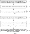
- the method of determining a fingerprint collection region may include the following steps S1-S3.
- a contact region is determined according to a touch signal generated by a touch operation from a starting moment t0 of sensing the touch operation.
- a change rate of a feature parameter of the contact region is determined.
- the fingerprint collection region is determined according to the contact region if the change rate is smaller than or equal to a preset change rate.
- the contact region may be determined according to the touch signals generated by the touch operation from the starting moment t0 of sensing the touch operation.
- Touch sensors may sense the touch operation and generate the touch signals.
- the contact region may be obtained by performing fitting according to the positions of the touch sensors generating the touch signals. For example, if the contact region is elliptical, determining the contact region includes determining at least the following four pieces of information: a length of an elliptical major axis, a length of an elliptical minor axis, a position of a center point and an included angle between the major axis and a terminal bezel or an included angle between the minor axis and the terminal bezel.
- the change rate of the feature parameter of the contact region may include a change rate of a contact region stress, a change rate of the elliptical major axis and a change rate of the elliptical minor axis.
- the change rate refers to a change in length within a unit time.
- the length may be represented by the number of touch sensors or the number of pixels.
- the preset change rate may be set to 3 pixels/100 milliseconds.
- the feature parameter of the contact region may change, for example, in stress and contact area, from a moment at which a finger of the user starts to contact the terminal device to a moment at which the finger completely presses on the terminal device.
- the change rate of the feature parameter of the contact region may be determined in this example. Take the change rate of the feature parameter of the contact region is the change rate of the area of the contact region as an example. If the change rate is smaller than or equal to the preset change rate, it indicates that the contact region tends to be stable, and the area of the contact region remains substantially unchanged as well.
- the fingerprint collection region may be determined according to the contact region (that is, the contact region determined when the change rate is smaller than or equal to the preset change rate).
- the determined contact region coincides with the contact region when the finger of the user completely presses on the terminal device. Further, it is ensured that the fingerprint collection region coinciding with the contact region when the finger of the user completely presses on the terminal device may be determined according to the determined contact region, and the fingerprint information may be completely collected by starting the fingerprint identification sensors in the fingerprint collection region.
- the preset area is not required to take the preset area as the determination criterion, which is helpful to avoid determining an operation of an intentional touch of the user as an unintentional touch.
- the determined fingerprint collection region coincides with the contact region when the finger of the user completely presses on the terminal device and the fingerprint collection region (the contact region) is a region covered by the finger of the user.
- the fingerprint identification sensors in the fingerprint collection region are photosensors, light emitted by the photosensors is still blocked by the finger of the user without light leakage, thereby improving the use experiences.
- all fingerprint identification sensors in the fingerprint collection region are controlled to perform fingerprint identification, all fingerprints of the fingerprint collection region may be identified, which helps to collect more fingerprint information and facilitate subsequent operations such as fingerprint identification and fingerprint authentication.
- the shape, position and area of the determined fingerprint collection region may be same as the shape, position and area of the contact region, and the inclination angle relative to the terminal bezel of the determined fingerprint collection region may be same as the inclination angle relative to the terminal bezel of the contact region.
- fingerprint identification may be performed by triggering the fingerprint identification sensors in the fingerprint collection region.
- the area of the contact region may also be considered in some embodiments of the present disclosure.
- the fingerprint collection region is determined according to the contact region when the area of the contact region is greater than or equal to a preset area and the change rate is smaller than or equal to a preset change rate.
- the preset area may be a small area, and may be represented by the number of touch sensors or the number of pixels.
- the area of the contact region is smaller than the preset area, for example, the area of the contact region is smaller than 10 pixels, it may be determined that the touch signals in the contact region is not generated by a user contacting the terminal device for collecting the fingerprint, which may be noise signals or an unintentional touch on the terminal device. Therefore, it is not required to determine the fingerprint collection region according to the contact region, reducing consumption of resources.
- the feature parameter is used to represent the area of the contact region.
- the feature parameter used for representing the area of the contact region in a case that the contact region is approximate to an ellipse, the feature parameter may include an elliptical major axis and an elliptical minor axis.
- the change rate of the feature parameter is smaller than or equal to the preset change rate, it may be more intuitively concluded that the area of the contact region tends to be stable, thereby it can determine the fingerprint collection region more accurately according to the contact region.
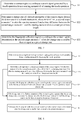
- FIG. 6 is a flowchart illustrating another method of determining a fingerprint collection region according to some embodiments of the present disclosure. As shown in FIG. 6 , determining the change rate of the feature parameter of the contact region includes the following step S21.
- the change rate of the feature parameter of the contact region from a first moment t1 to a second moment t2 is determined, where t0 ⁇ t1 ⁇ t2 ⁇ t', a first target moment t' is after the starting moment t0 and a time difference between the first target moment t' and the starting moment t0 is a first preset time length.
- Determining the fingerprint collection region according to the contact region includes the following step S31.
- the fingerprint collection region is determined according to the contact region determined at the first target moment t'.
- the change rate of the feature parameter of the contact region may be determined from the first moment t1 to the second moment t2 which are between t0 and t'.
- the first preset change rate refers to a change rate within a time range close to t'.
- the time range close to t' may be from (t'-10) ms to (t'+10) ms.
- the fingerprint collection region is determined according to the contact region determined at the first target moment t', that is, when the area of the contact region tends to be stable, the fingerprint collection region is determined according to the contact region when the area of the contact region between the finger of the user and the terminal device is maximum. Therefore, it may be ensured that the area of the determined fingerprint collection region is same as the maximum contact area between the finger and the terminal device when the user performs a touch operation, thereby the fingerprint information may be collected completely by starting the fingerprint identification sensors in the fingerprint collection region.
- t1 and t2 may be moments close to t'.
- a time length from t1 to t' is smaller than or equal to 1/3 of the first preset time length
- t2 is between t1 and t'
- t2 may even be equal to t'.
- a time length from a moment at which a finger starts to contact the terminal device to a moment at which an area of the contact region reaches the maximum area is the first preset time length.
- a time length from a moment at which a contact area between a finger and the terminal device is zero to a moment at which the contact area reaches the maximum area is the first preset time length. Therefore, the change rate of the contact area tends to be stable within the time range close to t', and the change rate of the contact area does not tend to be stable within a time range away from t', that is, it is highly probable that the change rate is greater than the first preset change rate.
- the change rate of the contact area is determined by selecting t1 and t2 within the time range close to t', i.e., the change rate of the feature parameter of the contact region may be determined within the time range close to t', which may accurately reflect whether the change rate of the contact area close to t' tends to be stable.
- the fingerprint collection region is determined according to the contact region, and the fingerprint information may be collected completely by starting the fingerprint identification sensors in the fingerprint collection region.
- the first preset time length is from a moment at which a finger starts to contact the terminal device to a moment at which a contact area between the finger and the terminal device reaches a stable maximum value.
- the stable maximum value of the contact area may refer to an area where the contact area between the finger and the terminal device no longer increases.
- the first preset time length may be determined by performing statistics based on big data.
- the first preset time length may be obtained by performing statistics for a large number of time lengths, each of which is from a moment at which a finger starts to contact the terminal device to a moment at which a contact area between the finger and the terminal reaches a stable maximum value, and by calculating an average value of the large number of time lengths.
- the first preset time length may be 300 milliseconds. That is, a time length from a moment at which a finger starts to contact the terminal device to a moment at which a contact area between the finger and the contact region reaches a stable maximum value is around 300 milliseconds.
- FIG. 7 is a flowchart illustrating another method of determining a fingerprint collection region according to some embodiments of the present disclosure. As shown in FIG. 7 , determining the change rate of the feature parameter of the contract region includes the following step S22.
- the change rate of the feature parameter of the contact region from a third moment t3 to a fourth moment t4 is determined, where t0 ⁇ t3 ⁇ t" ⁇ t4, a second target moment t" is after the starting moment t0 and a time difference between the second target moment t" and the starting moment t0 is a second preset time length.
- Determining the fingerprint collection region according to the contact region includes the following step S32.
- the fingerprint collection region is determined according to the contact region determined at the second target moment t".
- the change rate of the feature parameter of the contact region may be determined from the third moment t3 to the fourth moment t4 respectively at two sides of t".
- the change rate during this time, from t3 to t4 is smaller than or equal to a second preset change rate (the second preset change rate may be greater than or equal to the first preset change rate)
- the fingerprint collection region may be determined according to the contact region determined at the second target moment t".
- the fingerprint collection region is determined according to the contact region when the contact area between the finger of the user and the terminal device is larger.
- the area of the determined fingerprint collection region is approximate to the maximum contact area between the finger and the terminal device when the user performs a touch operation, so that relatively complete fingerprint information may be collected by starting the fingerprint identification sensors in the fingerprint collection region.
- the second preset time length is from a moment at which the finger starts to contact the terminal device to a moment at which the contact area between the finger and the contact region reaches a smooth rising period.
- the smooth rising period refers to a moment in which the contact area still changes but with a small change rate, for example, the change rate of the contact area is smaller than a preset change rate.
- the second preset time length may be determined by performing statistics based on big data.
- the second preset time length may be obtained by performing statistics for a large number of time lengths, each of which is from a moment at which the finger starts to contact the terminal device to a moment at which the contact area between the finger and the terminal device reaches a smooth rising period, and by calculating an average value of the large number of time lengths.
- the second preset time length may be 100 milliseconds. That is, a time length from a moment at which the finger starts to contact the terminal device to a moment at which the contact area between the finger and the contact region reaches a smooth rising period is around 100 milliseconds.
- FIG. 8 is a flowchart illustrating another method of determining a fingerprint collection region according to some embodiments of the present disclosure. As shown in FIG. 8 , the method further includes the following steps S4-S5.
- step S4 if the change rate of the feature parameter of the contact region is greater than the preset change rate, the change rate after the first target moment t' is determined until the change rate is smaller than or equal to the preset change rate.
- the fingerprint collection region is determined according to the contact region determined after the change rate is smaller than or equal to the preset change rate.
- the change rate is greater than the preset change rate, it indicates that the area of the contact region is not yet stable (for example, the user is still adjusting a posture for contacting the terminal device). In this case, it is not helpful to accurately collect a fingerprint pattern of the user.
- the change rate of the area of the contact region after the first target moment t' may be determined until the change rate is smaller than or equal to the preset change rate, and the fingerprint collection region may be determined according to the contact region determined after the change rate is smaller than or equal to the preset change rate.
- the fingerprint collection region may be determined according to the contact region, thereby ensuring that the determined contact region coincides with the contact region when the finger of the user completely presses on the terminal device. It is further ensured that the fingerprint collection region coinciding with the contact region when the finger of the user completely presses on the terminal device is determined according to the determined contact region.
- FIG. 9 is a flowchart illustrating another method of determining a fingerprint collection region according to some embodiments of the present disclosure. As shown in FIG. 9 , before the contact region is determined according to the touch signals, the method further includes the following steps S6-S7.
- step S6 a type of the touch operation is determined.
- a time length corresponding to the type is selected as the first preset time length.
- the terminal device will not collect the fingerprint pattern of the user and make response based on the collected fingerprint pattern until a delay of at least the first preset time length has passed.
- the type of the touch operation is determined, and the time length corresponding to the type is selected as the first preset time length. It can ensure that the selected first preset time length will be a delay suitable for the type of the touch operation, so as to maintain the user experience.
- the type includes fingerprint registration and fingerprint identification, and the first preset time length corresponding to the fingerprint registration is greater than the first preset time length corresponding to the fingerprint identification.
- the type of the touch operation may include fingerprint registration and fingerprint identification.
- a complete fingerprint pattern may be collected by registering the fingerprint of the user into the fingerprint identification sensors for multiple times, and therefore, the fingerprint registration usually takes long time. In this case, the delay tolerable by the user is longer.
- the first preset time length corresponding to the fingerprint registration may be set to be greater than the first preset time length corresponding to the fingerprint identification.
- the first preset time length corresponding to the fingerprint registration may be 300 milliseconds, and the first preset time length corresponding to the fingerprint identification may be 100 milliseconds.
- the first preset time length corresponding to the fingerprint identification in this example may be understood as the second preset time length in the above example shown in FIG. 7 . Therefore, when the type of the touch operation is the fingerprint identification, the change rate of the feature parameter of the contact region may be determined based on the above example shown in FIG. 7 .
- FIG. 10 is a flowchart illustrating another method of determining a fingerprint collection region according to some embodiments of the present disclosure. As shown in FIG. 10 , when the type of the touch operation is fingerprint identification, after the fingerprint collection region is determined according to the contact region, the method further includes the following step S8.
- the fingerprint collection region is expanded according to a preset proportional coefficient.
- the first preset time length corresponding to the fingerprint registration is greater than the first preset time length corresponding to the fingerprint identification, that is, the first preset time length corresponding to the fingerprint identification is shorter.
- the finger of the user may fail to complete an operation from a moment at which the finger starts to contact the terminal device to a moment at which the finger contacts the terminal device completely within the shorter first preset time length.
- the first preset time length corresponding to the fingerprint identification is 100 milliseconds, and the time length required from a moment at which the finger starts to contact the terminal device to a moment at which the finger contacts the terminal device completely is 300 milliseconds.
- the finger of the user starts contacting the terminal device for 100 milliseconds, the finger does not completely contact the terminal device, that is, the contact area is smaller than the contact area of completely contacting the terminal device. Therefore, the fingerprint collection region may be expanded according to the preset proportional coefficient, thereby collecting more complete fingerprint pattern of the user.
- the contact area between the finger and the terminal device is A; and when the finger of the user starts contacting the terminal device and maintains the contact for 300 milliseconds, the contact area between the finger and the terminal device is 112%A.
- the major axis and the minor axis of the contact region may be expanded respectively so that the area of the expanded contact region is 1.12 times of the contact area before expansion.
- the method further includes:
- the method may further include:
- the type includes fingerprint registration and fingerprint identification, and the second preset time length corresponding to the fingerprint registration is greater than the second preset time length corresponding to the fingerprint identification.
- the present disclosure further provides examples of apparatuses for determining a fingerprint collection region.
- FIG. 11 is a block diagram illustrating an apparatus for determining a fingerprint collection region according to some embodiments of the present disclosure.
- the apparatus for determining a fingerprint collection region according to some embodiments of the present disclosure may be applied to a terminal device such as a mobile phone, a tablet computer and a wearable device.
- the terminal device includes a touching circuit and a fingerprint identifying circuit.
- the touching circuit may include a plurality of touch sensors and a touch processor
- the fingerprint identifying circuit may include a plurality of fingerprint identification sensors and fingerprint identification processors.
- the touch sensors include but are not limited to mutual-inductive capacitive sensors and self-inductive capacitive sensors, and a specific type of the sensors may be selected according to requirements.
- the fingerprint identification sensors include but are not limited to photosensors and ultrasonic sensors, and a specific type of the sensors may be selected according to requirements.
- the terminal device may further include a display panel having touch sensors and the fingerprint identification sensors thereon.
- a region where the fingerprint identification sensors are disposed in some embodiments of the present disclosure may be far larger than a region where the fingerprint identification sensors are disposed in the related art.
- the apparatus for determining a fingerprint collection region includes:
- the feature parameter of the contact region is used to represent the area of the contact region.
- the change rate determining module 2 is configured to determine the change rate of the feature parameter of the contact region from a first moment t1 to a second moment t2, where t0 ⁇ t1 ⁇ t2 ⁇ t', a first target moment t' is after the starting moment t0 and a time difference between the first target moment t' and the starting moment t0 is a first preset time length.
- the collection region determining module 3 is configured to determine the fingerprint collection region according to the contact region determined at the first target moment t' when the change rate is smaller than or equal to a first preset change rate.
- the first preset time length is from a moment at which a finger starts to contact the terminal device to a moment at which a contact area between the finger and the terminal device reaches a stable maximum value.
- the change rate determining module 2 is configured to determine the change rate of the feature parameter of the contact region from a third moment t3 to a fourth moment t4, where t0 ⁇ t3 ⁇ t" ⁇ t4, a second target moment t" is after the starting moment t0 and a time difference between the second target moment t" and the starting moment t0 is a second preset time length.
- the collection region determining module 3 is configured to determine the fingerprint collection region according to the contact region determined at the second target moment t" when the change rate is smaller than or equal to a second preset change rate.
- the second preset time length is from a moment at which the finger starts to contact the terminal device to a moment at which the contact area between the finger and the terminal device reaches a smooth rising period.
- the change rate determining module 2 is further configured to, when the change rate of the area of the contact region is greater than the preset change rate, determine the change rate after the first target moment t' until the change rate is smaller than or equal to the preset change rate.
- the collection region determining module 3 is further configured to determine the fingerprint collection region according to the contact region determined after the change rate is smaller than or equal to the preset change rate.
- FIG. 12 is a block diagram illustrating another apparatus for determining a fingerprint collection region according to some embodiments of the present disclosure. As shown in FIG. 12 , the apparatus further includes:
- the type includes fingerprint registration and fingerprint identification, and the first preset time length corresponding to the fingerprint registration is greater than the first preset time length corresponding to the fingerprint identification.
- FIG. 13 is a block diagram illustrating another apparatus for determining a fingerprint collection region according to some embodiments of the present disclosure. As shown in FIG. 13 , when the type of the touch operation is the fingerprint identification, the apparatus further includes: a region expanding module 6, configured to expand the fingerprint collection region according to a preset proportional coefficient.
- the apparatus may further include: a fingerprint collection region determining module, configured to, when the change rate of the feature parameter of the contact region is greater than the preset change rate, determine the change rate after the fourth moment t4 until the change rate is smaller than or equal to another preset change rate (the second preset change rate), determine the fingerprint collection region according to the contact region determined after the change rate is smaller than or equal to the preset change rate.
- a fingerprint collection region determining module configured to, when the change rate of the feature parameter of the contact region is greater than the preset change rate, determine the change rate after the fourth moment t4 until the change rate is smaller than or equal to another preset change rate (the second preset change rate), determine the fingerprint collection region according to the contact region determined after the change rate is smaller than or equal to the preset change rate.
- the apparatus may further include: a second preset time length determining module, configured to determine a type of the touch operation and select a time length corresponding to the type as the second preset time length.
- a second preset time length determining module configured to determine a type of the touch operation and select a time length corresponding to the type as the second preset time length.
- the type includes fingerprint registration and fingerprint identification, and the second preset time length corresponding to the fingerprint registration is greater than the second preset time length corresponding to the fingerprint identification.
- the electronic device includes:
- the one or more processors are configured to execute steps of the method in any one of the examples described above.
- Some embodiments of the present disclosure further provide a computer readable storage medium storing computer programs.
- the programs are executed by the processor to implement steps of the method in any one of the examples described above.
- FIG. 14 is a block diagram illustrating an apparatus 1400 for determining a fingerprint collection region according to some embodiments of the present disclosure.
- the apparatus 1400 may include a mobile phone, a computer, a digital broadcast terminal, a message transceiving device, a game console, a tablet device, a medical device, a fitness device, a personal digital assistant, and the like.
- the apparatus 1400 may include one or more of the following components: a processing component 1402, a memory 1404, a power supply component 1406, a multimedia component 1408, an audio component 1410, an input/output (I/O) interface 1412, a sensor component 1414, and a communication component 1416.
- a processing component 1402 a memory 1404, a power supply component 1406, a multimedia component 1408, an audio component 1410, an input/output (I/O) interface 1412, a sensor component 1414, and a communication component 1416.
- the processing component 1402 generally controls overall operations of the apparatus 1400, such as operations associated with display, phone calls, data communications, camera operations and record operations.
- the processing component 1402 may include one or more processors 1420 to execute instructions to complete all or a part of steps of the above method.
- the processing component 1402 may include one or more modules which facilitate the interaction between the processing component 1402 and other components.
- the processing component 1402 may include a multimedia module to facilitate the interaction between the multimedia component 1408 and the processing component 1402.
- the memory 1404 is to store various types of data to support operations on the apparatus 1400. Examples of such data include instructions for any application or method that operates on the apparatus 1400 contact data, phonebook data, messages, pictures, videos, and so on.
- the memory 1404 may be implemented by any type of volatile or non-volatile storage devices or a combination thereof, such as a Static Random Access Memory (SRAM), an Electrically Erasable Programmable Read-Only Memory (EEPROM), an Erasable Programmable Read-Only Memory (EPROM), a Programmable Read-Only Memory (PROM), a Read-Only Memory (ROM), a magnetic memory, a flash memory, a magnetic disk or a compact disk.
- SRAM Static Random Access Memory
- EEPROM Electrically Erasable Programmable Read-Only Memory
- EPROM Erasable Programmable Read-Only Memory
- PROM Programmable Read-Only Memory
- ROM Read-Only Memory
- magnetic memory a magnetic memory
- flash memory a magnetic disk or a
- the power supply component 1406 supplies power for different components of the apparatus 1400.
- the power supply component 1406 may include a power supply management system, one or more power supplies, and other association components for generating, managing and distributing power for the apparatus 1400.
- circuits, device components, modules, units, blocks, or portions may have modular configurations, or are composed of discrete components, but nonetheless can be referred to as "units,” “modules,” or “portions” in general.
- the "circuits,” “components,” “modules,” “blocks,” “portions,” or “units” referred to herein may or may not be in modular forms.
- the multimedia component 1408 includes a screen providing an output interface between the apparatus 1400 and a user.
- the screen may include a Liquid Crystal Display (LCD) and a Touch Panel (TP).
- LCD Liquid Crystal Display
- TP Touch Panel
- OLED organic light-emitting diode
- the screen may be implemented as a touch screen to receive input signals from a user.
- the touch panel may include one or more touch sensors to sense a touch, a slide and a gesture on the touch panel.
- the touch sensors may not only sense a boundary of a touch or swipe, but also sense a duration and a pressure associated with the touch or swipe.
- the multimedia component 1408 may include a front camera and/or a rear camera.
- the front camera and/or rear camera may receive external multimedia data when the apparatus 1400 is in an operation mode, such as a photographing mode or a video mode.
- Each of the front camera and the rear camera may be a fixed optical lens system or have focal length and optical zooming capability.
- the audio component 1410 is to output and/or input an audio signal.
- the audio component 1410 includes a microphone (MIC).
- the microphone is configured to receive an external audio signal.
- the received audio signal may be further stored in the memory 1404 or sent via the communication component 1416.
- the audio component 1410 further includes a speaker for outputting an audio signal.
- the I/O interface 1412 provides an interface between the processing component 1402 and a peripheral interface module.
- the above peripheral interface module may be a keyboard, a click wheel, a button, or the like. These buttons may include but are not limited to, a home button, a volume button, a start button and a lock button.
- the sensor component 1414 includes one or more sensors to provide a status assessment of various aspects for the apparatus 1400.
- the sensor component 1414 may detect an on/off state of the apparatus 1400 and a relative positioning of components.
- the components are a display and a keypad of the apparatus 1400.
- the sensor component 1414 may also detect in position of the apparatus 1400 or a component of the apparatus 1400, a presence or absence of a contact between a user and the apparatus 1400, an orientation or acceleration/deceleration of the apparatus 1400, and a change in temperature of the apparatus 1400.
- the sensor component 1414 may include a proximity sensor to detect the presence of a nearby object without any physical touch.
- the sensor component 1414 may further include an optical sensor, such as a Complementary Metal-Oxide-Semiconductor (CMOS) or Charged Coupled Device (CCD) image sensor which is used in imaging applications.
- CMOS Complementary Metal-Oxide-Semiconductor
- CCD Charged Coupled Device
- the sensor component 1414 may further include an acceleration sensor, a gyro sensor, a magnetic sensor, a pressure sensor, or a temperature sensor.
- the communication component 1416 is to facilitate wired or wireless communication between the apparatus 1400 and other devices.
- the apparatus 1400 may access a wireless network based on a communication standard, such as WiFi, 2G or 3G, 4G LTE, 5G NR or a combination thereof.
- the communication component 1416 receives a broadcast signal or broadcast related information from an external broadcast management system via a broadcast channel.
- the communication component 1416 may further include a Near Field Communication (NFC) module for promoting short-range communication.
- the NFC module may be implemented based on radio frequency identification (RFID) technology, infrared data association (IrDA) technology, ultra-wideband (UWB) technology, Bluetooth (BT) technology and other technology.
- RFID radio frequency identification
- IrDA infrared data association
- UWB ultra-wideband
- Bluetooth Bluetooth
- the apparatus 1400 may be implemented by one or more of application specific integrated circuits (ASIC), digital signal processors (DSP), digital signal processing devices (DSPD), programmable logic devices (PLD), field programmable gate arrays (FPGA), controllers, microcontrollers, microprocessors or other electronic elements, for executing the method in any one of the examples described above.
- ASIC application specific integrated circuits
- DSP digital signal processors
- DSPD digital signal processing devices
- PLD programmable logic devices
- FPGA field programmable gate arrays
- controllers microcontrollers, microprocessors or other electronic elements, for executing the method in any one of the examples described above.
- non-transitory computer readable storage medium including instructions, such as the memory 1404 including instructions.
- the above instructions may be executed by the processor 1420 of the apparatus 1400 to complete the above method.
- the non-transitory computer readable storage medium may be a Read-Only Memory (ROM), a Random-Access Memory (RAM), a CD-ROM, a magnetic tape, a floppy disk and an optical data storage device, etc.
- modules/units can each be implemented by hardware, or software, or a combination of hardware and software.
- modules/units may be combined as one module/unit, and each of the above described modules/units may be further divided into a plurality of sub-modules/sub-units.
- first and second are used for descriptive purposes only and are not to be construed as indicating or implying a relative importance or implicitly indicating the number of technical features indicated.
- elements referred to as “first” and “second” may include one or more of the features either explicitly or implicitly.
- a plurality indicates two or more unless specifically defined otherwise.
- the terms “installed,” “connected,” “coupled,” “fixed” and the like shall be understood broadly, and may be either a fixed connection or a detachable connection, or integrated, unless otherwise explicitly defined. These terms can refer to mechanical or electrical connections, or both. Such connections can be direct connections or indirect connections through an intermediate medium. These terms can also refer to the internal connections or the interactions between elements. The specific meanings of the above terms in the present disclosure can be understood by those of ordinary skill in the art on a case-by-case basis.
- a first element being "on,” “over,” or “below” a second element may indicate direct contact between the first and second elements, without contact, or indirect through an intermediate medium, unless otherwise explicitly stated and defined.
- a first element being "above,” “over,” or “at an upper surface of' a second element may indicate that the first element is directly above the second element, or merely that the first element is at a level higher than the second element.
- the first element “below,” “underneath,” or “at a lower surface of' the second element may indicate that the first element is directly below the second element, or merely that the first element is at a level lower than the second feature.
- the first and second elements may or may not be in contact with each other.
- the terms “one embodiment,” “some embodiments,” “example,” “specific example,” or “some examples,” and the like may indicate a specific feature described in connection with the embodiment or example, a structure, a material or feature included in at least one embodiment or example.
- the schematic representation of the above terms is not necessarily directed to the same embodiment or example.
- control and/or interface software or app can be provided in a form of a non-transitory computer-readable storage medium having instructions stored thereon is further provided.
- the non-transitory computer-readable storage medium may be a Read-Only Memory (ROM), a Random-Access Memory (RAM), a Compact Disc Read-Only Memory (CD-ROM), a magnetic tape, a floppy disk, optical data storage equipment, a flash drive such as a USB drive or an SD card, and the like.
- Implementations of the subject matter and the operations described in this disclosure can be implemented in digital electronic circuitry, or in computer software, firmware, or hardware, including the structures disclosed herein and their structural equivalents, or in combinations of one or more of them. Implementations of the subject matter described in this disclosure can be implemented as one or more computer programs, i.e., one or more modules of computer program instructions, encoded on one or more computer storage medium for execution by, or to control the operation of, data processing apparatus.
- the program instructions can be encoded on an artificially-generated propagated signal, e.g., a machine-generated electrical, optical, or electromagnetic signal, that is generated to encode information for transmission to suitable receiver apparatus for execution by a data processing apparatus.
- an artificially-generated propagated signal e.g., a machine-generated electrical, optical, or electromagnetic signal
- a computer storage medium can be, or be included in, a computer-readable storage device, a computer-readable storage substrate, a random or serial access memory array or device, or a combination of one or more of them.
- a computer storage medium is not a propagated signal
- a computer storage medium can be a source or destination of computer program instructions encoded in an artificially-generated propagated signal.
- the computer storage medium can also be, or be included in, one or more separate components or media (e.g., multiple CDs, disks, drives, or other storage devices). Accordingly, the computer storage medium may be tangible.
- the operations described in this disclosure can be implemented as operations performed by a data processing apparatus on data stored on one or more computer-readable storage devices or received from other sources.
- the devices in this disclosure can include special purpose logic circuitry, e.g., an FPGA (field-programmable gate array), or an ASIC (application-specific integrated circuit).
- the device can also include, in addition to hardware, code that creates an execution environment for the computer program in question, e.g., code that constitutes processor firmware, a protocol stack, a database management system, an operating system, a cross-platform runtime environment, a virtual machine, or a combination of one or more of them.
- the devices and execution environment can realize various different computing model infrastructures, such as web services, distributed computing, and grid computing infrastructures.
- the devices can be controlled remotely through the Internet, on a smart phone, a tablet computer or other types of computers, with a web-based graphic user interface (GUI).
- GUI graphic user interface
- a computer program (also known as a program, software, software application, app, script, or code) can be written in any form of programming language, including compiled or interpreted languages, declarative or procedural languages, and it can be deployed in any form, including as a stand-alone program or as a module, component, subroutine, object, or other unit suitable for use in a computing environment.
- a computer program may, but need not, correspond to a file in a file system.
- a program can be stored in a portion of a file that holds other programs or data (e.g., one or more scripts stored in a mark-up language document), in a single file dedicated to the program in question, or in multiple coordinated files (e.g., files that store one or more modules, sub-programs, or portions of code).
- a computer program can be deployed to be executed on one computer or on multiple computers that are located at one site or distributed across multiple sites and interconnected by a communication network.
- the processes and logic flows described in this disclosure can be performed by one or more programmable processors executing one or more computer programs to perform actions by operating on input data and generating output.
- the processes and logic flows can also be performed by, and apparatus can also be implemented as, special purpose logic circuitry, e.g., an FPGA, or an ASIC.
- processors or processing circuits suitable for the execution of a computer program include, by way of example, both general and special purpose microprocessors, and any one or more processors of any kind of digital computer.
- a processor will receive instructions and data from a read-only memory, or a random-access memory, or both.
- Elements of a computer can include a processor configured to perform actions in accordance with instructions and one or more memory devices for storing instructions and data.
- a computer will also include, or be operatively coupled to receive data from or transfer data to, or both, one or more mass storage devices for storing data, e.g., magnetic, magneto-optical disks, or optical disks.
- mass storage devices for storing data
- a computer need not have such devices.
- a computer can be embedded in another device, e.g., a mobile telephone, a personal digital assistant (PDA), a mobile audio or video player, a game console, a Global Positioning System (GPS) receiver, or a portable storage device (e.g., a universal serial bus (USB) flash drive), to name just a few.
- PDA personal digital assistant
- GPS Global Positioning System
- USB universal serial bus
- Devices suitable for storing computer program instructions and data include all forms of non-volatile memory, media and memory devices, including by way of example semiconductor memory devices, e.g., EPROM, EEPROM, and flash memory devices; magnetic disks, e.g., internal hard disks or removable disks; magneto-optical disks; and CD-ROM and DVD-ROM disks.
- semiconductor memory devices e.g., EPROM, EEPROM, and flash memory devices
- magnetic disks e.g., internal hard disks or removable disks
- magneto-optical disks e.g., CD-ROM and DVD-ROM disks.
- the processor and the memory can be supplemented by, or incorporated in, special purpose logic circuitry.
- implementations of the subject matter described in this specification can be implemented with a computer and/or a display device, e.g., a VR/AR device, ahead-mount display (HMD) device, a head-up display (HUD) device, smart eyewear (e.g., glasses), a CRT (cathode-ray tube), LCD (liquid-crystal display), OLED (organic light emitting diode) display, other flexible configuration, or any other monitor for displaying information to the user and a keyboard, a pointing device, e.g., a mouse, trackball, etc., or a touch screen, touch pad, etc., by which the user can provide input to the computer.
- a display device e.g., a VR/AR device, ahead-mount display (HMD) device, a head-up display (HUD) device, smart eyewear (e.g., glasses), a CRT (cathode-ray tube), LCD (liquid-crystal display), OLED (organic light emitting
- feedback provided to the user can be any form of sensory feedback, e.g., visual feedback, auditory feedback, or tactile feedback; and input from the user can be received in any form, including acoustic, speech, or tactile input.
- a user can speak commands to the audio processing device, to perform various operations.
- Implementations of the subject matter described in this specification can be implemented in a computing system that includes a back-end component, e.g., as a data server, or that includes a middleware component, e.g., an application server, or that includes a front-end component, e.g., a client computer having a graphical user interface or a Web browser through which a user can interact with an implementation of the subject matter described in this specification, or any combination of one or more such back-end, middleware, or front-end components.
- the components of the system can be interconnected by any form or medium of digital data communication, e.g., a communication network.
- Examples of communication networks include a local area network (“LAN”) and a wide area network (“WAN”), an inter-network (e.g., the Internet), and peer-to-peer networks (e.g., ad hoc peer-to-peer networks).
- LAN local area network
- WAN wide area network
- inter-network e.g., the Internet
- peer-to-peer networks e.g., ad hoc peer-to-peer networks.
Landscapes
- Engineering & Computer Science (AREA)
- Theoretical Computer Science (AREA)
- Physics & Mathematics (AREA)
- General Physics & Mathematics (AREA)
- General Engineering & Computer Science (AREA)
- Human Computer Interaction (AREA)
- Multimedia (AREA)
- Computer Security & Cryptography (AREA)
- Computer Hardware Design (AREA)
- Software Systems (AREA)
- Image Input (AREA)
- Telephone Function (AREA)
Abstract
Description
- The present disclosure relates to the field of fingerprint collection technology, and more specifically to a method and an apparatus for determining a fingerprint collection region, an electronic device and a non-transitory computer readable storage medium.
- With the development of fingerprint identification technologies, under-screen fingerprint identification are realized in many terminal devices, where fingerprint identification can be performed by using fingerprint identification sensors disposed in a display region of the terminal device.
- The present disclosure relates generally to the field of fingerprint identification technologies, and more specifically to a method and an apparatus for determining a fingerprint collection region, an electronic device, and a non-transitory computer readable storage medium.
- According to a first aspect of the present disclosure, a method of determining a fingerprint collection region is provided. The method includes: determining a contact region according to a touch signal generated by a touch operation from a starting moment t0 of sensing the touch operation; determining a change rate of a feature parameter of the contact region; and determining the fingerprint collection region according to the contact region when the change rate is smaller than or equal to a preset change rate.
- According to a second aspect of the present disclosure, there an apparatus for determining a fingerprint collection region is provided. The apparatus includes: a contact region determining module, configured to determine a contact region according to a touch signal generated by a touch operation from a starting moment t0 of sensing the touch operation; a change rate determining module, configured to determine a change rate of a feature parameter of the contact region; and a collection region determining module, configured to determine the fingerprint collection region according to the contact region when the change rate is smaller than or equal to a preset change rate.
- According to a third aspect of the present disclosure, an electronic device is provided. The electronic device includes: one or more processors; and a memory for storing processor executable instructions. The one or more processors are configured to determine a contact region according to a touch signal generated by a touch operation from a starting moment t0 of sensing the touch operation; determine a change rate of a feature parameter of the contact region; and determine the fingerprint collection region according to the contact region when the change rate is smaller than or equal to a preset change rate.
- According to a fourth aspect of the present disclosure, a non-transitory computer readable storage medium storing computer programs is provided, where the programs are executed by one or more processors to determine a contact region according to a touch signal generated by a touch operation from a starting moment t0 of sensing the touch operation; determine a change rate of a feature parameter of the contact region; and determine the fingerprint collection region according to the contact region when the change rate is smaller than or equal to a preset change rate.
- It is to be understood that the above general descriptions and the below detailed descriptions are merely exemplary and explanatory, and are not intended to limit the present disclosure.
- The accompanying drawings, which are incorporated in and constitute a part of the present disclosure, illustrate examples consistent with the present disclosure and serve to explain the principles of the present disclosure together with the specification.
-
FIG. 1 is a schematic diagram illustrating a mobile phone having a fingerprint collection region according to some embodiments. -
FIG. 2 is a schematic diagram illustrating a relationship of a contact region and a fingerprint collection region on a mobile phone according to some embodiments. -
FIG. 3 is a schematic diagram illustrating another relationship of a contact region and a fingerprint collection region on a mobile phone according to some embodiments. -
FIG. 4 is a schematic diagram illustrating still another relationship of a contact region and a fingerprint collection region on a mobile phone according to some embodiments. -
FIG. 5 is a flowchart illustrating a method of determining a fingerprint collection region according to some embodiments of the present disclosure. -
FIG. 6 is a flowchart illustrating another method of determining a fingerprint collection region according to some embodiments of the present disclosure. -
FIG. 7 is a flowchart illustrating another method of determining a fingerprint collection region according to some embodiments of the present disclosure. -
FIG. 8 is a flowchart illustrating another method of determining a fingerprint collection region according to some embodiments of the present disclosure. -
FIG. 9 is a flowchart illustrating another method of determining a fingerprint collection region according to some embodiments of the present disclosure. -
FIG. 10 is a flowchart illustrating another method of determining a fingerprint collection region according to some embodiments of the present disclosure. -
FIG. 11 is a block diagram illustrating an apparatus for determining a fingerprint collection region according to some embodiments of the present disclosure. -
FIG. 12 is a block diagram illustrating another apparatus for determining a fingerprint collection region according to some embodiments of the present disclosure. -
FIG. 13 is a block diagram illustrating another apparatus for determining a fingerprint collection region according to some embodiments of the present disclosure. -
FIG. 14 is a block diagram illustrating an apparatus for determining a fingerprint collection region according to some embodiments of the present disclosure. - Examples will be described in detail herein, with the illustrations thereof represented in the drawings. When the following descriptions involve the drawings, like numerals in different drawings refer to like or similar elements unless otherwise indicated. The embodiments described in the following examples do not represent all embodiments consistent with the present disclosure. Rather, they are merely examples of apparatuses and methods consistent with some aspects of the present disclosure as detailed in the appended claims.
- The manner of performing fingerprint identification can be limited on a mobile device such as a mobile phone. For example, in determining a contact region by a user on a terminal device, a "gravity" center (or center of force) of the contact region is determined, typically by calculating a weighted average of touch signals (i.e. weighted according to the force of each touch signal). However, because the user may apply a different force at various positions of a finger when touching a terminal device, the gravity center determined in this way may not coincide with an actual center or geometrical center (centroid) of the contact region.
- When the gravity center is located in a fingerprint identification region, a circular region is determined with the gravity center as a center of the circle based on a fixed radius, and all fingerprint identification sensors within the circular region are started to perform fingerprint identification. For example, as shown in
FIG. 1 , when a gravity center of a contact region is located in a fingerprint collection region, the gravity center is taken as the center, acircular region 101 is determined with the gravity center as the center of the circular region based on a fixed radius so that fingerprints within thecircular region 101 are identified. - However, since the gravity center may not coincide with the center of the contact region, the contact region within the circular region may be a small part of a contact region between the user and the terminal device, resulting in incomplete collected fingerprint information. For example, when the user performs a fingerprint identification operation, a shape of the contact region between a finger and a screen is not circular.
- For example, as shown in
FIG. 2 , the shape of thecontact region 102 between the finger of the user and the terminal device is elliptical, and the contact region may not cover the circular region in the fingerprint collection region, so that a gap exists between the contact region and the circular region. When all fingerprint identification sensors, for example, photosensors, within the circular region are started, since the photosensors at the gap are not blocked by the finger, and the light leakage will be observed by the user in the case shown inFIG. 2 , thereby affecting the use experiences. Further, the collected fingerprint information may not cover even a half of the contact region, resulting in the incomplete collected fingerprint information. - Even if the
contact region 102 is completely located within thecircular region 101 as shown inFIG. 3 , since the radius of thecircular region 101 is fixed, the user can only contact the fingerprint collection region with a part of the finger, for example, a fingertip. As a result, the light leakage problem indicated inFIG. 2 still exists, and less fingerprint information is collected, which is not desirable for the fingerprint identification. - If the circular region is reduced to avoid the light leakage problem as shown in
FIG. 4 , since the circular region 101 (a region indicated by a dotted line) located in thecontact region 102 is a small area, and less fingerprint information is collected, which affecting the fingerprint identification. -
FIG. 5 is a flowchart illustrating a method of determining a fingerprint collection region according to some embodiments of the present disclosure, which can be applied to or improve upon various devices such as the mobile phones illustrated inFIGS. 1-4 , or other terminal devices such as a mobile phone, a tablet computer and a wearable device. The terminal device includes a touching circuit and a fingerprint identifying circuit. The touching circuit may include a plurality of touch sensors and a touch processor, and the fingerprint identifying circuit may include a plurality of fingerprint identification sensors and a fingerprint identification processor. - The touch sensors include but are not limited to mutual-inductive capacitive sensors and self-inductive capacitive sensors, and a specific type of the sensors may be selected according to requirements. The fingerprint identification sensors include but are not limited to photosensors and ultrasonic sensors, and a specific type of the sensor may be selected according to requirements.
- In some embodiments, the terminal device may further include a display panel having touch sensors and the fingerprint identification sensors thereon.
- It is noted that a region where the fingerprint identification sensors are disposed in some embodiments of the present disclosure may be far larger than a region where the fingerprint identification sensors are disposed in the related art.
- For example, as shown in
FIG. 1 , the region where the fingerprint identification sensors are disposed in the related art is a small region with a fixed shape and size at a lower half portion of the display panel. When fingerprint registration or fingerprint identification is performed, all the fingerprint identification sensors within the region are started. - However, a region where the fingerprint identification sensors are disposed in some embodiments of the present disclosure may be a half region of the display panel or even the entire display panel. In this case, when fingerprint registration or fingerprint identification is performed, only the fingerprint identification sensors in the fingerprint collection region within the region are started.
- In the related art, to avoid collecting the fingerprint of an unintentional touch, whether a contact area is greater than a preset area is determined before the fingerprint collection region is determined. When the contact area is greater than the preset area, it is determined that the user does not touch unintentionally, so that the fingerprint collection region is to be determined, and the fingerprint is collected through the fingerprint identification sensors within the fingerprint collection region.
- However, there is a problem in the existing way of determining whether the user unintentionally touches the terminal device according to the contact area. Since different human fingers have different widths and lengths, the contact areas between the finger and the terminal device may also be different. Some users do not unintentionally touch the terminal device, but the contact area between the finger and the terminal device is small. If the preset area is taken as a determination criterion, an operation of an intentional touch of the user may be determined as an unintentional touch. Then, the fingerprint will not be collected, resulting in no response to the operation of the user and affecting the use experience.
- As shown in
FIG. 5 , the method of determining a fingerprint collection region may include the following steps S1-S3. - At step S1, a contact region is determined according to a touch signal generated by a touch operation from a starting moment t0 of sensing the touch operation.
- At step S2, a change rate of a feature parameter of the contact region is determined.
- At step S3, the fingerprint collection region is determined according to the contact region if the change rate is smaller than or equal to a preset change rate.
- In some embodiments, the contact region may be determined according to the touch signals generated by the touch operation from the starting moment t0 of sensing the touch operation. Touch sensors may sense the touch operation and generate the touch signals. The contact region may be obtained by performing fitting according to the positions of the touch sensors generating the touch signals. For example, if the contact region is elliptical, determining the contact region includes determining at least the following four pieces of information: a length of an elliptical major axis, a length of an elliptical minor axis, a position of a center point and an included angle between the major axis and a terminal bezel or an included angle between the minor axis and the terminal bezel.
- A position, a shape and an area of the contact region and an inclination angle of the contact region relative to the terminal bezel are determined according to the above four pieces of information, then the contact region may be determined accurately. The change rate of the feature parameter of the contact region may include a change rate of a contact region stress, a change rate of the elliptical major axis and a change rate of the elliptical minor axis. The change rate refers to a change in length within a unit time. In this example, the length may be represented by the number of touch sensors or the number of pixels. For example, if the length is represented by the number of pixels, the preset change rate may be set to 3 pixels/100 milliseconds.
- The feature parameter of the contact region may change, for example, in stress and contact area, from a moment at which a finger of the user starts to contact the terminal device to a moment at which the finger completely presses on the terminal device. The change rate of the feature parameter of the contact region may be determined in this example. Take the change rate of the feature parameter of the contact region is the change rate of the area of the contact region as an example. If the change rate is smaller than or equal to the preset change rate, it indicates that the contact region tends to be stable, and the area of the contact region remains substantially unchanged as well. The fingerprint collection region may be determined according to the contact region (that is, the contact region determined when the change rate is smaller than or equal to the preset change rate). Therefore, it is ensured that the determined contact region coincides with the contact region when the finger of the user completely presses on the terminal device. Further, it is ensured that the fingerprint collection region coinciding with the contact region when the finger of the user completely presses on the terminal device may be determined according to the determined contact region, and the fingerprint information may be completely collected by starting the fingerprint identification sensors in the fingerprint collection region.
- According to some embodiments of the present disclosure, it is not required to take the preset area as the determination criterion, which is helpful to avoid determining an operation of an intentional touch of the user as an unintentional touch.
- According to some embodiments of the present disclosure, the determined fingerprint collection region coincides with the contact region when the finger of the user completely presses on the terminal device and the fingerprint collection region (the contact region) is a region covered by the finger of the user. Thus, even if the fingerprint identification sensors in the fingerprint collection region are photosensors, light emitted by the photosensors is still blocked by the finger of the user without light leakage, thereby improving the use experiences.
- According to some embodiments of the present disclosure, since all fingerprint identification sensors in the fingerprint collection region are controlled to perform fingerprint identification, all fingerprints of the fingerprint collection region may be identified, which helps to collect more fingerprint information and facilitate subsequent operations such as fingerprint identification and fingerprint authentication.
- The shape, position and area of the determined fingerprint collection region may be same as the shape, position and area of the contact region, and the inclination angle relative to the terminal bezel of the determined fingerprint collection region may be same as the inclination angle relative to the terminal bezel of the contact region. After the fingerprint collection region is determined, fingerprint identification may be performed by triggering the fingerprint identification sensors in the fingerprint collection region.
- Preferably, the area of the contact region may also be considered in some embodiments of the present disclosure. The fingerprint collection region is determined according to the contact region when the area of the contact region is greater than or equal to a preset area and the change rate is smaller than or equal to a preset change rate. The preset area may be a small area, and may be represented by the number of touch sensors or the number of pixels. When the area of the contact region is smaller than the preset area, for example, the area of the contact region is smaller than 10 pixels, it may be determined that the touch signals in the contact region is not generated by a user contacting the terminal device for collecting the fingerprint, which may be noise signals or an unintentional touch on the terminal device. Therefore, it is not required to determine the fingerprint collection region according to the contact region, reducing consumption of resources.
- Preferably, the feature parameter is used to represent the area of the contact region.
- In some embodiments, the feature parameter used for representing the area of the contact region, in a case that the contact region is approximate to an ellipse, the feature parameter may include an elliptical major axis and an elliptical minor axis. When the change rate of the feature parameter is smaller than or equal to the preset change rate, it may be more intuitively concluded that the area of the contact region tends to be stable, thereby it can determine the fingerprint collection region more accurately according to the contact region.
-
FIG. 6 is a flowchart illustrating another method of determining a fingerprint collection region according to some embodiments of the present disclosure. As shown inFIG. 6 , determining the change rate of the feature parameter of the contact region includes the following step S21. - At step S21, the change rate of the feature parameter of the contact region from a first moment t1 to a second moment t2 is determined, where t0≤t1<t2≤t', a first target moment t' is after the starting moment t0 and a time difference between the first target moment t' and the starting moment t0 is a first preset time length.
- Determining the fingerprint collection region according to the contact region includes the following step S31.
- At step S31, the fingerprint collection region is determined according to the contact region determined at the first target moment t'.
- In this example, the change rate of the feature parameter of the contact region may be determined from the first moment t1 to the second moment t2 which are between t0 and t'. When the change rate from the moment t1 until the moment t2 is smaller than or equal to a first preset change rate, it may be determined that the area of the contact region tends to be stable. The first preset change rate refers to a change rate within a time range close to t'. The time range close to t' may be from (t'-10) ms to (t'+10) ms. In other words, when the change rate is smaller than or equal to the first preset change rate, the area of the contact region no longer increases or increases by a small amount. Thus, the fingerprint collection region is determined according to the contact region determined at the first target moment t', that is, when the area of the contact region tends to be stable, the fingerprint collection region is determined according to the contact region when the area of the contact region between the finger of the user and the terminal device is maximum. Therefore, it may be ensured that the area of the determined fingerprint collection region is same as the maximum contact area between the finger and the terminal device when the user performs a touch operation, thereby the fingerprint information may be collected completely by starting the fingerprint identification sensors in the fingerprint collection region.
- Preferably, t1 and t2 may be moments close to t'. For example, a time length from t1 to t' is smaller than or equal to 1/3 of the first preset time length, t2 is between t1 and t', and t2 may even be equal to t'.
- Generally, a time length from a moment at which a finger starts to contact the terminal device to a moment at which an area of the contact region reaches the maximum area is the first preset time length. In other words, a time length from a moment at which a contact area between a finger and the terminal device is zero to a moment at which the contact area reaches the maximum area is the first preset time length. Therefore, the change rate of the contact area tends to be stable within the time range close to t', and the change rate of the contact area does not tend to be stable within a time range away from t', that is, it is highly probable that the change rate is greater than the first preset change rate.
- If the change rate of the feature parameter of the contact region is determined within a time range away from t', it is highly probably concluded that the change rate of the contact area does not tend to be stable. However, since the contact area within the time range away from t' is usually unstable, the obtained conclusion that the change rate of the contact area does not tend to be stable cannot accurately reflect whether the change rate of the contact area close to t' tends to be stable.
- According to this example, the change rate of the contact area is determined by selecting t1 and t2 within the time range close to t', i.e., the change rate of the feature parameter of the contact region may be determined within the time range close to t', which may accurately reflect whether the change rate of the contact area close to t' tends to be stable. Further, when the contact area tends to be stable, the fingerprint collection region is determined according to the contact region, and the fingerprint information may be collected completely by starting the fingerprint identification sensors in the fingerprint collection region.
- Optionally, the first preset time length is from a moment at which a finger starts to contact the terminal device to a moment at which a contact area between the finger and the terminal device reaches a stable maximum value. The stable maximum value of the contact area may refer to an area where the contact area between the finger and the terminal device no longer increases.
- In some embodiments, the first preset time length, i.e., t'-t0, may be determined by performing statistics based on big data. For example, the first preset time length may be obtained by performing statistics for a large number of time lengths, each of which is from a moment at which a finger starts to contact the terminal device to a moment at which a contact area between the finger and the terminal reaches a stable maximum value, and by calculating an average value of the large number of time lengths. For example, the first preset time length may be 300 milliseconds. That is, a time length from a moment at which a finger starts to contact the terminal device to a moment at which a contact area between the finger and the contact region reaches a stable maximum value is around 300 milliseconds.
-
FIG. 7 is a flowchart illustrating another method of determining a fingerprint collection region according to some embodiments of the present disclosure. As shown inFIG. 7 , determining the change rate of the feature parameter of the contract region includes the following step S22. - At step S22, the change rate of the feature parameter of the contact region from a third moment t3 to a fourth moment t4 is determined, where t0≤t3<t"<t4, a second target moment t" is after the starting moment t0 and a time difference between the second target moment t" and the starting moment t0 is a second preset time length.
- Determining the fingerprint collection region according to the contact region includes the following step S32.
- At step S32, the fingerprint collection region is determined according to the contact region determined at the second target moment t".
- In this example, the change rate of the feature parameter of the contact region may be determined from the third moment t3 to the fourth moment t4 respectively at two sides of t". When the change rate during this time, from t3 to t4, is smaller than or equal to a second preset change rate (the second preset change rate may be greater than or equal to the first preset change rate), it may be determined that the area of the contact region tends to be stable (by comparing the area of the contact region tending to be stable in this example with the area of the contact region tending to be stable indicated in the example shown in
FIG. 6 , the area of the contact region indicated in the example shown inFIG. 6 may be more stable). Therefore, the fingerprint collection region may be determined according to the contact region determined at the second target moment t". That is, when the area of the contact region tends to be stable, the fingerprint collection region is determined according to the contact region when the contact area between the finger of the user and the terminal device is larger. Thus, it may be ensured that the area of the determined fingerprint collection region is approximate to the maximum contact area between the finger and the terminal device when the user performs a touch operation, so that relatively complete fingerprint information may be collected by starting the fingerprint identification sensors in the fingerprint collection region. - Optionally, the second preset time length is from a moment at which the finger starts to contact the terminal device to a moment at which the contact area between the finger and the contact region reaches a smooth rising period. The smooth rising period refers to a moment in which the contact area still changes but with a small change rate, for example, the change rate of the contact area is smaller than a preset change rate.
- In some embodiments, the second preset time length, i.e., t"-t0, may be determined by performing statistics based on big data. For example, the second preset time length may be obtained by performing statistics for a large number of time lengths, each of which is from a moment at which the finger starts to contact the terminal device to a moment at which the contact area between the finger and the terminal device reaches a smooth rising period, and by calculating an average value of the large number of time lengths. For example, the second preset time length may be 100 milliseconds. That is, a time length from a moment at which the finger starts to contact the terminal device to a moment at which the contact area between the finger and the contact region reaches a smooth rising period is around 100 milliseconds.
-
FIG. 8 is a flowchart illustrating another method of determining a fingerprint collection region according to some embodiments of the present disclosure. As shown inFIG. 8 , the method further includes the following steps S4-S5. - At step S4, if the change rate of the feature parameter of the contact region is greater than the preset change rate, the change rate after the first target moment t' is determined until the change rate is smaller than or equal to the preset change rate.
- At step S5, the fingerprint collection region is determined according to the contact region determined after the change rate is smaller than or equal to the preset change rate.
- In some embodiments, if the change rate is greater than the preset change rate, it indicates that the area of the contact region is not yet stable (for example, the user is still adjusting a posture for contacting the terminal device). In this case, it is not helpful to accurately collect a fingerprint pattern of the user.
- In this example, the change rate of the area of the contact region after the first target moment t' may be determined until the change rate is smaller than or equal to the preset change rate, and the fingerprint collection region may be determined according to the contact region determined after the change rate is smaller than or equal to the preset change rate. As a result, when the area of the contact region tends to be stable, the fingerprint collection region may be determined according to the contact region, thereby ensuring that the determined contact region coincides with the contact region when the finger of the user completely presses on the terminal device. It is further ensured that the fingerprint collection region coinciding with the contact region when the finger of the user completely presses on the terminal device is determined according to the determined contact region.
-
FIG. 9 is a flowchart illustrating another method of determining a fingerprint collection region according to some embodiments of the present disclosure. As shown inFIG. 9 , before the contact region is determined according to the touch signals, the method further includes the following steps S6-S7. - At step S6, a type of the touch operation is determined.
- At step S7, a time length corresponding to the type is selected as the first preset time length.
- In some embodiments, there is a first preset time length between the first target moment t' and a starting moment t0 of sensing the touch operation, in other words, from a moment when the user starts touching the terminal device, the terminal device will not collect the fingerprint pattern of the user and make response based on the collected fingerprint pattern until a delay of at least the first preset time length has passed.
- However, for different types of touch operations, delays acceptable to the user are different. In the example, the type of the touch operation is determined, and the time length corresponding to the type is selected as the first preset time length. It can ensure that the selected first preset time length will be a delay suitable for the type of the touch operation, so as to maintain the user experience.
- Optionally, the type includes fingerprint registration and fingerprint identification, and the first preset time length corresponding to the fingerprint registration is greater than the first preset time length corresponding to the fingerprint identification.
- In some embodiments, the type of the touch operation may include fingerprint registration and fingerprint identification. Generally, a complete fingerprint pattern may be collected by registering the fingerprint of the user into the fingerprint identification sensors for multiple times, and therefore, the fingerprint registration usually takes long time. In this case, the delay tolerable by the user is longer.
- For the fingerprint identification, for example, fingerprint identification for unlocking and fingerprint identification for payment which generally are all instant operations, and the user needs to quickly see an operation result. In this case, the delay tolerable by the user is generally short. Therefore, the first preset time length corresponding to the fingerprint registration may be set to be greater than the first preset time length corresponding to the fingerprint identification.
- For example, the first preset time length corresponding to the fingerprint registration may be 300 milliseconds, and the first preset time length corresponding to the fingerprint identification may be 100 milliseconds.
- It is to be noted that the first preset time length corresponding to the fingerprint identification in this example may be understood as the second preset time length in the above example shown in
FIG. 7 . Therefore, when the type of the touch operation is the fingerprint identification, the change rate of the feature parameter of the contact region may be determined based on the above example shown inFIG. 7 . -
FIG. 10 is a flowchart illustrating another method of determining a fingerprint collection region according to some embodiments of the present disclosure. As shown inFIG. 10 , when the type of the touch operation is fingerprint identification, after the fingerprint collection region is determined according to the contact region, the method further includes the following step S8. - At step S8, the fingerprint collection region is expanded according to a preset proportional coefficient.
- In some embodiments, since the first preset time length corresponding to the fingerprint registration is greater than the first preset time length corresponding to the fingerprint identification, that is, the first preset time length corresponding to the fingerprint identification is shorter. The finger of the user may fail to complete an operation from a moment at which the finger starts to contact the terminal device to a moment at which the finger contacts the terminal device completely within the shorter first preset time length.
- For example, the first preset time length corresponding to the fingerprint identification is 100 milliseconds, and the time length required from a moment at which the finger starts to contact the terminal device to a moment at which the finger contacts the terminal device completely is 300 milliseconds. After the finger of the user starts contacting the terminal device for 100 milliseconds, the finger does not completely contact the terminal device, that is, the contact area is smaller than the contact area of completely contacting the terminal device. Therefore, the fingerprint collection region may be expanded according to the preset proportional coefficient, thereby collecting more complete fingerprint pattern of the user.
- For example, when the finger of the user starts contacting the terminal device and maintains the contact for 100 milliseconds, the contact area between the finger and the terminal device is A; and when the finger of the user starts contacting the terminal device and maintains the contact for 300 milliseconds, the contact area between the finger and the terminal device is 112%A. In this case, after the finger starts contacting the terminal device for 100 milliseconds, the major axis and the minor axis of the contact region may be expanded respectively so that the area of the expanded contact region is 1.12 times of the contact area before expansion.
- Optionally, the method further includes:
- if the change rate of the feature parameter of the contact region is greater than another preset change rate (a second preset change rate), determining the change rate after the fourth moment t4 until the change rate is smaller than or equal to the preset change rate; and
- determining the fingerprint collection region according to the contact region determined after the change rate is smaller than or equal to the preset change rate.
- Optionally, before the contact region is determined according to the touch signals, the method may further include:
- determining a type of the touch operation; and
- selecting a time length corresponding to the type as the second preset time length.
- Optionally, the type includes fingerprint registration and fingerprint identification, and the second preset time length corresponding to the fingerprint registration is greater than the second preset time length corresponding to the fingerprint identification.
- Corresponding to the foregoing examples of methods of determining a fingerprint collection region, the present disclosure further provides examples of apparatuses for determining a fingerprint collection region.
-
FIG. 11 is a block diagram illustrating an apparatus for determining a fingerprint collection region according to some embodiments of the present disclosure. The apparatus for determining a fingerprint collection region according to some embodiments of the present disclosure may be applied to a terminal device such as a mobile phone, a tablet computer and a wearable device. The terminal device includes a touching circuit and a fingerprint identifying circuit. The touching circuit may include a plurality of touch sensors and a touch processor, and the fingerprint identifying circuit may include a plurality of fingerprint identification sensors and fingerprint identification processors. - The touch sensors include but are not limited to mutual-inductive capacitive sensors and self-inductive capacitive sensors, and a specific type of the sensors may be selected according to requirements. The fingerprint identification sensors include but are not limited to photosensors and ultrasonic sensors, and a specific type of the sensors may be selected according to requirements.
- In some embodiments, the terminal device may further include a display panel having touch sensors and the fingerprint identification sensors thereon.
- It is to be noted that a region where the fingerprint identification sensors are disposed in some embodiments of the present disclosure may be far larger than a region where the fingerprint identification sensors are disposed in the related art.
- As shown in
FIG. 11 , the apparatus for determining a fingerprint collection region includes: - a contact
region determining module 1, configured to determine a contact region according to a touch signal generated by a touch operation from a starting moment t0 of sensing the touch operation; - a change
rate determining module 2, configured to determine a change rate of a feature parameter of the contact region; and - a collection
region determining module 3, configured to determine the fingerprint collection region according to the contact region when the change rate is smaller than or equal to a preset change rate. - Optionally, the feature parameter of the contact region is used to represent the area of the contact region.
- Optionally, the change
rate determining module 2 is configured to determine the change rate of the feature parameter of the contact region from a first moment t1 to a second moment t2, where t0≤t1<t2≤t', a first target moment t' is after the starting moment t0 and a time difference between the first target moment t' and the starting moment t0 is a first preset time length. - The collection
region determining module 3 is configured to determine the fingerprint collection region according to the contact region determined at the first target moment t' when the change rate is smaller than or equal to a first preset change rate. - Optionally, the first preset time length is from a moment at which a finger starts to contact the terminal device to a moment at which a contact area between the finger and the terminal device reaches a stable maximum value.
- The change
rate determining module 2 is configured to determine the change rate of the feature parameter of the contact region from a third moment t3 to a fourth moment t4, where t0≤t3<t"<t4, a second target moment t" is after the starting moment t0 and a time difference between the second target moment t" and the starting moment t0 is a second preset time length. - The collection
region determining module 3 is configured to determine the fingerprint collection region according to the contact region determined at the second target moment t" when the change rate is smaller than or equal to a second preset change rate. - Optionally, the second preset time length is from a moment at which the finger starts to contact the terminal device to a moment at which the contact area between the finger and the terminal device reaches a smooth rising period.
- Optionally, the change
rate determining module 2 is further configured to, when the change rate of the area of the contact region is greater than the preset change rate, determine the change rate after the first target moment t' until the change rate is smaller than or equal to the preset change rate. - The collection
region determining module 3 is further configured to determine the fingerprint collection region according to the contact region determined after the change rate is smaller than or equal to the preset change rate. -
FIG. 12 is a block diagram illustrating another apparatus for determining a fingerprint collection region according to some embodiments of the present disclosure. As shown inFIG. 12 , the apparatus further includes: - a
type determining module 4, configured to determine a type of the touch operation; and - a time
length selecting module 5, configured to select a time length corresponding to the type as the first preset time length. - Optionally, the type includes fingerprint registration and fingerprint identification, and the first preset time length corresponding to the fingerprint registration is greater than the first preset time length corresponding to the fingerprint identification.
-
FIG. 13 is a block diagram illustrating another apparatus for determining a fingerprint collection region according to some embodiments of the present disclosure. As shown inFIG. 13 , when the type of the touch operation is the fingerprint identification, the apparatus further includes:
aregion expanding module 6, configured to expand the fingerprint collection region according to a preset proportional coefficient. - A specific manner in which each module of the apparatus in the above example performs an operation has been already described in detail in the relevant method examples, details of which will not be repeated herein.
- Optionally, the apparatus may further include:
a fingerprint collection region determining module, configured to, when the change rate of the feature parameter of the contact region is greater than the preset change rate, determine the change rate after the fourth moment t4 until the change rate is smaller than or equal to another preset change rate (the second preset change rate), determine the fingerprint collection region according to the contact region determined after the change rate is smaller than or equal to the preset change rate. - Optionally, the apparatus may further include:
a second preset time length determining module, configured to determine a type of the touch operation and select a time length corresponding to the type as the second preset time length. - Optionally, the type includes fingerprint registration and fingerprint identification, and the second preset time length corresponding to the fingerprint registration is greater than the second preset time length corresponding to the fingerprint identification.
- For the apparatus examples, since it basically corresponds to the method examples, reference may be made to the partial description of the method examples. The apparatus examples described above are merely illustrative, where the modules described as separate components may be or not be physically separate, and the components displayed as modules may or may not be physical modules, that is., may be located at one place, or may also be distributed to multiple network modules. Some or all of the modules may be selected according to actual needs to achieve the objectives of the present disclosure. It can be understood and implemented by those of ordinary skill in the art without any creative effort.
- Some embodiments of the present disclosure further provide an electronic device. The electronic device includes:
- one or more processors; and
- a memory for storing processor executable instructions.
- The one or more processors are configured to execute steps of the method in any one of the examples described above.
- Some embodiments of the present disclosure further provide a computer readable storage medium storing computer programs. The programs are executed by the processor to implement steps of the method in any one of the examples described above.
-
FIG. 14 is a block diagram illustrating anapparatus 1400 for determining a fingerprint collection region according to some embodiments of the present disclosure. For example, theapparatus 1400 may include a mobile phone, a computer, a digital broadcast terminal, a message transceiving device, a game console, a tablet device, a medical device, a fitness device, a personal digital assistant, and the like. - As shown in
FIG. 14 , theapparatus 1400 may include one or more of the following components: aprocessing component 1402, amemory 1404, apower supply component 1406, amultimedia component 1408, anaudio component 1410, an input/output (I/O)interface 1412, asensor component 1414, and acommunication component 1416. - The
processing component 1402 generally controls overall operations of theapparatus 1400, such as operations associated with display, phone calls, data communications, camera operations and record operations. Theprocessing component 1402 may include one ormore processors 1420 to execute instructions to complete all or a part of steps of the above method. Further, theprocessing component 1402 may include one or more modules which facilitate the interaction between theprocessing component 1402 and other components. For example, theprocessing component 1402 may include a multimedia module to facilitate the interaction between themultimedia component 1408 and theprocessing component 1402. - The
memory 1404 is to store various types of data to support operations on theapparatus 1400. Examples of such data include instructions for any application or method that operates on theapparatus 1400 contact data, phonebook data, messages, pictures, videos, and so on. Thememory 1404 may be implemented by any type of volatile or non-volatile storage devices or a combination thereof, such as a Static Random Access Memory (SRAM), an Electrically Erasable Programmable Read-Only Memory (EEPROM), an Erasable Programmable Read-Only Memory (EPROM), a Programmable Read-Only Memory (PROM), a Read-Only Memory (ROM), a magnetic memory, a flash memory, a magnetic disk or a compact disk. - The
power supply component 1406 supplies power for different components of theapparatus 1400. Thepower supply component 1406 may include a power supply management system, one or more power supplies, and other association components for generating, managing and distributing power for theapparatus 1400. - The various circuits, device components, modules, units, blocks, or portions may have modular configurations, or are composed of discrete components, but nonetheless can be referred to as "units," "modules," or "portions" in general. In other words, the "circuits," "components," "modules," "blocks," "portions," or "units" referred to herein may or may not be in modular forms.
- The
multimedia component 1408 includes a screen providing an output interface between theapparatus 1400 and a user. In some examples, the screen may include a Liquid Crystal Display (LCD) and a Touch Panel (TP). In some embodiments, an organic light-emitting diode (OLED) display or other types of displays can be adopted. - If the screen includes the touch panel, the screen may be implemented as a touch screen to receive input signals from a user. The touch panel may include one or more touch sensors to sense a touch, a slide and a gesture on the touch panel. The touch sensors may not only sense a boundary of a touch or swipe, but also sense a duration and a pressure associated with the touch or swipe. In some examples, the
multimedia component 1408 may include a front camera and/or a rear camera. The front camera and/or rear camera may receive external multimedia data when theapparatus 1400 is in an operation mode, such as a photographing mode or a video mode. Each of the front camera and the rear camera may be a fixed optical lens system or have focal length and optical zooming capability. - The
audio component 1410 is to output and/or input an audio signal. For example, theaudio component 1410 includes a microphone (MIC). When theapparatus 1400 is in an operable mode, such as a call mode, a record mode and a voice identification mode, the microphone is configured to receive an external audio signal. The received audio signal may be further stored in thememory 1404 or sent via thecommunication component 1416. In some examples, theaudio component 1410 further includes a speaker for outputting an audio signal. - The I/
O interface 1412 provides an interface between theprocessing component 1402 and a peripheral interface module. The above peripheral interface module may be a keyboard, a click wheel, a button, or the like. These buttons may include but are not limited to, a home button, a volume button, a start button and a lock button. - The
sensor component 1414 includes one or more sensors to provide a status assessment of various aspects for theapparatus 1400. For example, thesensor component 1414 may detect an on/off state of theapparatus 1400 and a relative positioning of components. For example, the components are a display and a keypad of theapparatus 1400. Thesensor component 1414 may also detect in position of theapparatus 1400 or a component of theapparatus 1400, a presence or absence of a contact between a user and theapparatus 1400, an orientation or acceleration/deceleration of theapparatus 1400, and a change in temperature of theapparatus 1400. Thesensor component 1414 may include a proximity sensor to detect the presence of a nearby object without any physical touch. Thesensor component 1414 may further include an optical sensor, such as a Complementary Metal-Oxide-Semiconductor (CMOS) or Charged Coupled Device (CCD) image sensor which is used in imaging applications. In some examples, thesensor component 1414 may further include an acceleration sensor, a gyro sensor, a magnetic sensor, a pressure sensor, or a temperature sensor. - The
communication component 1416 is to facilitate wired or wireless communication between theapparatus 1400 and other devices. Theapparatus 1400 may access a wireless network based on a communication standard, such as WiFi, 2G or 3G, 4G LTE, 5G NR or a combination thereof. In some embodiments, thecommunication component 1416 receives a broadcast signal or broadcast related information from an external broadcast management system via a broadcast channel. In some embodiments, thecommunication component 1416 may further include a Near Field Communication (NFC) module for promoting short-range communication. For example, the NFC module may be implemented based on radio frequency identification (RFID) technology, infrared data association (IrDA) technology, ultra-wideband (UWB) technology, Bluetooth (BT) technology and other technology. - In some embodiments, the
apparatus 1400 may be implemented by one or more of application specific integrated circuits (ASIC), digital signal processors (DSP), digital signal processing devices (DSPD), programmable logic devices (PLD), field programmable gate arrays (FPGA), controllers, microcontrollers, microprocessors or other electronic elements, for executing the method in any one of the examples described above. - In some embodiments, there is further provided a non-transitory computer readable storage medium including instructions, such as the
memory 1404 including instructions. The above instructions may be executed by theprocessor 1420 of theapparatus 1400 to complete the above method. For example, the non-transitory computer readable storage medium may be a Read-Only Memory (ROM), a Random-Access Memory (RAM), a CD-ROM, a magnetic tape, a floppy disk and an optical data storage device, etc. - Those of ordinary skill in the art will understand that the above described modules/units can each be implemented by hardware, or software, or a combination of hardware and software. Those of ordinary skill in the art will also understand that multiple ones of the above described modules/units may be combined as one module/unit, and each of the above described modules/units may be further divided into a plurality of sub-modules/sub-units.
- In the present disclosure, it is to be understood that the terms "lower," "upper," "center," "longitudinal," "transverse," "length," "width," "thickness," "upper," "lower," "front," "back," "left," "right," "vertical," "horizontal," "top," "bottom," "inside," "outside," "clockwise," "counterclockwise," "axial," "radial," "circumferential," "column," "row," and other orientation or positional relationships are based on example orientations illustrated in the drawings, and are merely for the convenience of the description of some embodiments, rather than indicating or implying the device or component being constructed and operated in a particular orientation. Therefore, these terms are not to be construed as limiting the scope of the present disclosure.
- Moreover, the terms "first" and "second" are used for descriptive purposes only and are not to be construed as indicating or implying a relative importance or implicitly indicating the number of technical features indicated. Thus, elements referred to as "first" and "second" may include one or more of the features either explicitly or implicitly. In the description of the present disclosure, "a plurality" indicates two or more unless specifically defined otherwise.
- In the present disclosure, the terms "installed," "connected," "coupled," "fixed" and the like shall be understood broadly, and may be either a fixed connection or a detachable connection, or integrated, unless otherwise explicitly defined. These terms can refer to mechanical or electrical connections, or both. Such connections can be direct connections or indirect connections through an intermediate medium. These terms can also refer to the internal connections or the interactions between elements. The specific meanings of the above terms in the present disclosure can be understood by those of ordinary skill in the art on a case-by-case basis.
- In the present disclosure, a first element being "on," "over," or "below" a second element may indicate direct contact between the first and second elements, without contact, or indirect through an intermediate medium, unless otherwise explicitly stated and defined.
- Moreover, a first element being "above," "over," or "at an upper surface of' a second element may indicate that the first element is directly above the second element, or merely that the first element is at a level higher than the second element. The first element "below," "underneath," or "at a lower surface of' the second element may indicate that the first element is directly below the second element, or merely that the first element is at a level lower than the second feature. The first and second elements may or may not be in contact with each other.
- In the description of the present disclosure, the terms "one embodiment," "some embodiments," "example," "specific example," or "some examples," and the like may indicate a specific feature described in connection with the embodiment or example, a structure, a material or feature included in at least one embodiment or example. In the present disclosure, the schematic representation of the above terms is not necessarily directed to the same embodiment or example.
- Moreover, the particular features, structures, materials, or characteristics described may be combined in a suitable manner in any one or more embodiments or examples. In addition, various embodiments or examples described in the specification, as well as features of various embodiments or examples, may be combined and reorganized.
- In some embodiments, the control and/or interface software or app can be provided in a form of a non-transitory computer-readable storage medium having instructions stored thereon is further provided. For example, the non-transitory computer-readable storage medium may be a Read-Only Memory (ROM), a Random-Access Memory (RAM), a Compact Disc Read-Only Memory (CD-ROM), a magnetic tape, a floppy disk, optical data storage equipment, a flash drive such as a USB drive or an SD card, and the like.
- Implementations of the subject matter and the operations described in this disclosure can be implemented in digital electronic circuitry, or in computer software, firmware, or hardware, including the structures disclosed herein and their structural equivalents, or in combinations of one or more of them. Implementations of the subject matter described in this disclosure can be implemented as one or more computer programs, i.e., one or more modules of computer program instructions, encoded on one or more computer storage medium for execution by, or to control the operation of, data processing apparatus.
- Alternatively, or in addition, the program instructions can be encoded on an artificially-generated propagated signal, e.g., a machine-generated electrical, optical, or electromagnetic signal, that is generated to encode information for transmission to suitable receiver apparatus for execution by a data processing apparatus. A computer storage medium can be, or be included in, a computer-readable storage device, a computer-readable storage substrate, a random or serial access memory array or device, or a combination of one or more of them.
- Moreover, while a computer storage medium is not a propagated signal, a computer storage medium can be a source or destination of computer program instructions encoded in an artificially-generated propagated signal. The computer storage medium can also be, or be included in, one or more separate components or media (e.g., multiple CDs, disks, drives, or other storage devices). Accordingly, the computer storage medium may be tangible.
- The operations described in this disclosure can be implemented as operations performed by a data processing apparatus on data stored on one or more computer-readable storage devices or received from other sources.
- The devices in this disclosure can include special purpose logic circuitry, e.g., an FPGA (field-programmable gate array), or an ASIC (application-specific integrated circuit). The device can also include, in addition to hardware, code that creates an execution environment for the computer program in question, e.g., code that constitutes processor firmware, a protocol stack, a database management system, an operating system, a cross-platform runtime environment, a virtual machine, or a combination of one or more of them. The devices and execution environment can realize various different computing model infrastructures, such as web services, distributed computing, and grid computing infrastructures. For example, the devices can be controlled remotely through the Internet, on a smart phone, a tablet computer or other types of computers, with a web-based graphic user interface (GUI).
- A computer program (also known as a program, software, software application, app, script, or code) can be written in any form of programming language, including compiled or interpreted languages, declarative or procedural languages, and it can be deployed in any form, including as a stand-alone program or as a module, component, subroutine, object, or other unit suitable for use in a computing environment. A computer program may, but need not, correspond to a file in a file system. A program can be stored in a portion of a file that holds other programs or data (e.g., one or more scripts stored in a mark-up language document), in a single file dedicated to the program in question, or in multiple coordinated files (e.g., files that store one or more modules, sub-programs, or portions of code). A computer program can be deployed to be executed on one computer or on multiple computers that are located at one site or distributed across multiple sites and interconnected by a communication network.
- The processes and logic flows described in this disclosure can be performed by one or more programmable processors executing one or more computer programs to perform actions by operating on input data and generating output. The processes and logic flows can also be performed by, and apparatus can also be implemented as, special purpose logic circuitry, e.g., an FPGA, or an ASIC.
- Processors or processing circuits suitable for the execution of a computer program include, by way of example, both general and special purpose microprocessors, and any one or more processors of any kind of digital computer. Generally, a processor will receive instructions and data from a read-only memory, or a random-access memory, or both. Elements of a computer can include a processor configured to perform actions in accordance with instructions and one or more memory devices for storing instructions and data.
- Generally, a computer will also include, or be operatively coupled to receive data from or transfer data to, or both, one or more mass storage devices for storing data, e.g., magnetic, magneto-optical disks, or optical disks. However, a computer need not have such devices. Moreover, a computer can be embedded in another device, e.g., a mobile telephone, a personal digital assistant (PDA), a mobile audio or video player, a game console, a Global Positioning System (GPS) receiver, or a portable storage device (e.g., a universal serial bus (USB) flash drive), to name just a few.
- Devices suitable for storing computer program instructions and data include all forms of non-volatile memory, media and memory devices, including by way of example semiconductor memory devices, e.g., EPROM, EEPROM, and flash memory devices; magnetic disks, e.g., internal hard disks or removable disks; magneto-optical disks; and CD-ROM and DVD-ROM disks. The processor and the memory can be supplemented by, or incorporated in, special purpose logic circuitry.
- To provide for interaction with a user, implementations of the subject matter described in this specification can be implemented with a computer and/or a display device, e.g., a VR/AR device, ahead-mount display (HMD) device, a head-up display (HUD) device, smart eyewear (e.g., glasses), a CRT (cathode-ray tube), LCD (liquid-crystal display), OLED (organic light emitting diode) display, other flexible configuration, or any other monitor for displaying information to the user and a keyboard, a pointing device, e.g., a mouse, trackball, etc., or a touch screen, touch pad, etc., by which the user can provide input to the computer.
- Other types of devices can be used to provide for interaction with a user as well; for example, feedback provided to the user can be any form of sensory feedback, e.g., visual feedback, auditory feedback, or tactile feedback; and input from the user can be received in any form, including acoustic, speech, or tactile input. In an example, a user can speak commands to the audio processing device, to perform various operations.
- Implementations of the subject matter described in this specification can be implemented in a computing system that includes a back-end component, e.g., as a data server, or that includes a middleware component, e.g., an application server, or that includes a front-end component, e.g., a client computer having a graphical user interface or a Web browser through which a user can interact with an implementation of the subject matter described in this specification, or any combination of one or more such back-end, middleware, or front-end components. The components of the system can be interconnected by any form or medium of digital data communication, e.g., a communication network. Examples of communication networks include a local area network ("LAN") and a wide area network ("WAN"), an inter-network (e.g., the Internet), and peer-to-peer networks (e.g., ad hoc peer-to-peer networks).
- While this specification contains many specific implementation details, these should not be construed as limitations on the scope of any claims, but rather as descriptions of features specific to particular implementations. Certain features that are described in this specification in the context of separate implementations can also be implemented in combination in a single implementation. Conversely, various features that are described in the context of a single implementation can also be implemented in multiple implementations separately or in any suitable subcombinations.
- Moreover, although features may be described above as acting in certain combinations and even initially claimed as such, one or more features from a claimed combination can in some cases be excised from the combination, and the claimed combination may be directed to a subcombination or variations of a subcombination.
- Similarly, while operations are depicted in the drawings in a particular order, this should not be understood as requiring that such operations be performed in the particular order shown or in sequential order, or that all illustrated operations be performed, to achieve desirable results. In certain circumstances, multitasking and parallel processing may be advantageous. Moreover, the separation of various system components in the implementations described above should not be understood as requiring such separation in all implementations, and it should be understood that the described program components and systems can generally be integrated together in a single software product or packaged into multiple software products.
- Thus, particular implementations of the subject matter have been described. Other implementations are within the scope of the following claims. In some cases, the actions recited in the claims can be performed in a different order and still achieve desirable results. In addition, the processes depicted in the accompanying figures do not necessarily require the particular order shown, or sequential order, to achieve desirable results. In certain implementations, multitasking or parallel processing may be utilized.
- It is intended that the specification and embodiments be considered as examples only. Other embodiments of the disclosure will be apparent to those skilled in the art in view of the specification and drawings of the present disclosure. That is, although specific embodiments have been described above in detail, the description is merely for purposes of illustration. It should be appreciated, therefore, that many aspects described above are not intended as required or essential elements unless explicitly stated otherwise.
- Various modifications of, and equivalent acts corresponding to, the disclosed aspects of the example embodiments, in addition to those described above, can be made by a person of ordinary skill in the art, having the benefit of the present disclosure, without departing from the scope of the disclosure defined in the following claims, the scope of which is to be accorded the broadest interpretation so as to encompass such modifications and equivalent structures.
Claims (15)
- A method of determining a fingerprint collection region, the method being applied to a terminal device, and comprising:determining a contact region according to a touch signal generated by a touch operation from a starting moment t0 of sensing the touch operation;determining a change rate of a feature parameter of the contact region; anddetermining the fingerprint collection region according to the contact region when the change rate is smaller than or equal to a preset change rate.
- The method according to claim 1, wherein the feature parameter is used to represent an area of the contact region.
- The method according to any of claims 1-2, wherein determining the change rate of the feature parameter of the contact region comprises:determining the change rate of the feature parameter of the contact region from a first moment t1 to a second moment t2, wherein t0≤t1<t2≤t', a first target moment t' is after the starting moment t0 and a time difference between the first target moment t' and the starting moment t0 is a first preset time length; andwherein determining the fingerprint collection region according to the contact region comprises: determining the fingerprint collection region according to the contact region determined at the first target moment t' when the change rate is smaller than or equal to a first preset change rate.
- The method according to claim 3, wherein the first preset time length is from a moment at which a finger starts to contact the terminal device to a moment at which a contact area between the finger and the terminal device reaches a stable maximum value.
- The method according to any of claims 1-2, wherein determining the change rate of the feature parameter of the contact region comprises:determining the change rate of the feature parameter of the contact region from a third moment t3 to a fourth moment t4, wherein t0≤t3<t"<t4, a second target moment t" is after the starting moment t0 and a time difference between the second target moment t" and the starting moment t0 is a second preset time length; andwherein determining the fingerprint collection region according to the contact region comprises: determining the fingerprint collection region according to the contact region determined at the second target moment t" when the change rate is smaller than or equal to a second preset change rate.
- The method according to claim 5, wherein the second preset time length is from a moment at which a finger starts to contact the terminal device to a moment at which a contact area between the finger and the terminal device reaches a smooth rising period.
- The method according to claim 3, further comprising:when the change rate of the feature parameter of the contact region is greater than the preset change rate, determining the change rate after the first target moment t' until the change rate is smaller than or equal to the preset change rate; anddetermining the fingerprint collection region according to the contact region determined after the change rate is smaller than or equal to the preset change rate.
- The method according to claim 3, wherein the method further comprises:determining a type of the touch operation; andselecting a time length corresponding to the type as the first preset time length.
- The method according to claim 8, wherein the type comprises fingerprint registration and fingerprint identification, and the first preset time length corresponding to the fingerprint registration is greater than the first preset time length corresponding to the fingerprint identification.
- The method according to claim 1, wherein when the type of the touch operation is the fingerprint identification, the method further comprises:
expanding the fingerprint collection region according to a preset proportional coefficient. - An apparatus for determining a fingerprint collection region, the apparatus being applied to a terminal device, and comprising:a contact region determining module, configured to determine a contact region according to a touch signal generated by a touch operation from a starting moment t0 of sensing the touch operation;a change rate determining module, configured to determine a change rate of a feature parameter of the contact region; anda collection region determining module, configured to determine the fingerprint collection region according to the contact region when the change rate is smaller than or equal to a preset change rate.
- The apparatus according to claim 11, wherein determining the change rate of the feature parameter of the contact region comprises:determining the change rate of the feature parameter of the contact region from a first moment t1 to a second moment t2, wherein t0≤t1<t2≤t', a first target moment t' is after the starting moment t0 and a time difference between the first target moment t' and the starting moment t0 is a first preset time length; andwherein determining the fingerprint collection region according to the contact region comprises: determining the fingerprint collection region according to the contact region determined at the first target moment t' when the change rate is smaller than or equal to a first preset change rate.
- The apparatus according to claim 11, wherein determining the change rate of the feature parameter of the contact region comprises:determining the change rate of the feature parameter of the contact region from a third moment t3 to a fourth moment t4, wherein t0≤t3<t"<t4, a second target moment t" is after the starting moment t0 and a time difference between the second target moment t" and the starting moment t0 is a second preset time length; andwherein determining the fingerprint collection region according to the contact region comprises: determining the fingerprint collection region according to the contact region determined at the second target moment t" when the change rate is smaller than or equal to a second preset change rate.
- An electronic device, comprising:one or more processors; anda memory for storing processor executable instructions,wherein when the instructions are invoked, the one or more processors are caused to perform operations in accordance with the method of any of claims 1-10.
- A non-transitory computer readable storage medium storing computer programs, wherein when the programs are executed by one or more processors, the one or more processors are caused to perform operations in accordance with the method of any of claims 1-10.
Applications Claiming Priority (1)
| Application Number | Priority Date | Filing Date | Title |
|---|---|---|---|
| CN201910193012.3A CN111695382B (en) | 2019-03-14 | 2019-03-14 | Fingerprint collection area determination method and fingerprint collection area determination device |
Publications (2)
| Publication Number | Publication Date |
|---|---|
| EP3709147A1 true EP3709147A1 (en) | 2020-09-16 |
| EP3709147B1 EP3709147B1 (en) | 2022-03-02 |
Family
ID=68944175
Family Applications (1)
| Application Number | Title | Priority Date | Filing Date |
|---|---|---|---|
| EP19216905.0A Active EP3709147B1 (en) | 2019-03-14 | 2019-12-17 | Method and apparatus for determining fingerprint collection region |
Country Status (3)
| Country | Link |
|---|---|
| US (1) | US11087116B2 (en) |
| EP (1) | EP3709147B1 (en) |
| CN (1) | CN111695382B (en) |
Families Citing this family (8)
| Publication number | Priority date | Publication date | Assignee | Title |
|---|---|---|---|---|
| EP3679519B1 (en) * | 2017-09-07 | 2024-11-06 | Fingerprint Cards Anacatum IP AB | Method and fingerprint sensing system for determining finger contact with a fingerprint sensor |
| CN111488761B (en) * | 2019-01-25 | 2024-04-26 | 北京小米移动软件有限公司 | Fingerprint identification method, device, electronic device and computer-readable storage medium |
| CN111695382B (en) | 2019-03-14 | 2024-02-13 | 北京小米移动软件有限公司 | Fingerprint collection area determination method and fingerprint collection area determination device |
| US11475705B2 (en) * | 2019-12-05 | 2022-10-18 | Novatek Microelectronics Corp. | Method for fingerprint recognition and fingerprint recognition device |
| CN112416174B (en) * | 2020-11-25 | 2022-11-25 | 信利(仁寿)高端显示科技有限公司 | Touch display panel light leakage analysis method, touch display panel and manufacturing method |
| CN112684970B (en) * | 2020-12-31 | 2022-11-29 | 腾讯科技(深圳)有限公司 | Adaptive display method and device of virtual scene, electronic equipment and storage medium |
| TWI766550B (en) * | 2021-01-20 | 2022-06-01 | 速博思股份有限公司 | Touch control method |
| CN113568524B (en) * | 2021-07-20 | 2023-09-08 | 中国银联股份有限公司 | Touch screen behavior detection method and device, electronic equipment and storage medium |
Citations (4)
| Publication number | Priority date | Publication date | Assignee | Title |
|---|---|---|---|---|
| WO2013173838A2 (en) * | 2012-05-18 | 2013-11-21 | Apple Inc. | Device, method, and graphical user interface for manipulating user interfaces based on fingerprint sensor inputs |
| CN107704744A (en) * | 2017-09-05 | 2018-02-16 | 广东欧珀移动通信有限公司 | Identity verification method, device and mobile terminal |
| EP3358455A1 (en) * | 2017-02-03 | 2018-08-08 | Samsung Electronics Co., Ltd. | Apparatus and method for controlling fingerprint sensor |
| EP3396515A1 (en) * | 2017-04-28 | 2018-10-31 | Guangdong Oppo Mobile Telecommunications Corp., Ltd. | Method for displaying fingerprint identification area and mobile terminal |
Family Cites Families (16)
| Publication number | Priority date | Publication date | Assignee | Title |
|---|---|---|---|---|
| TWI457842B (en) | 2010-09-29 | 2014-10-21 | Gingy Technology Inc | A segmented image recognition method and a region identification device thereof |
| US9898642B2 (en) | 2013-09-09 | 2018-02-20 | Apple Inc. | Device, method, and graphical user interface for manipulating user interfaces based on fingerprint sensor inputs |
| KR102123092B1 (en) | 2013-11-21 | 2020-06-15 | 삼성전자주식회사 | Method for identifying fingerprint and electronic device thereof |
| KR102177150B1 (en) * | 2014-02-19 | 2020-11-10 | 삼성전자 주식회사 | Apparatus and method for recognizing a fingerprint |
| US9734379B2 (en) | 2014-09-03 | 2017-08-15 | Fingerprint Cards Ab | Guided fingerprint enrollment |
| KR102290892B1 (en) | 2014-12-12 | 2021-08-19 | 엘지전자 주식회사 | Mobile terminal and method for controlling the same |
| KR102338864B1 (en) | 2015-02-12 | 2021-12-13 | 삼성전자주식회사 | Electronic device and method for registration finger print |
| CN106570442B (en) | 2015-10-09 | 2021-05-14 | 小米科技有限责任公司 | Fingerprint identification method and device |
| CN106203290B (en) * | 2016-06-28 | 2018-03-02 | 广东欧珀移动通信有限公司 | A kind of fingerprint image acquisition method and terminal |
| CN107194331B (en) | 2017-05-08 | 2019-04-12 | 维沃移动通信有限公司 | A kind of fingerprint identification method and mobile terminal |
| US11354934B2 (en) | 2018-05-03 | 2022-06-07 | Microsoft Technology Licensing, Llc | Location matched small segment fingerprint reader |
| WO2020056771A1 (en) * | 2018-09-21 | 2020-03-26 | 深圳市汇顶科技股份有限公司 | Fingerprint identification apparatus and electronic device |
| KR102734293B1 (en) | 2018-12-10 | 2024-11-26 | 삼성전자주식회사 | Method and apparatus for preprocessing fingerprint image |
| CN111488761B (en) | 2019-01-25 | 2024-04-26 | 北京小米移动软件有限公司 | Fingerprint identification method, device, electronic device and computer-readable storage medium |
| US11074428B2 (en) | 2019-01-30 | 2021-07-27 | Novatek Microelectronics Corp. | Fingerprint identification device and method |
| CN111695382B (en) | 2019-03-14 | 2024-02-13 | 北京小米移动软件有限公司 | Fingerprint collection area determination method and fingerprint collection area determination device |
-
2019
- 2019-03-14 CN CN201910193012.3A patent/CN111695382B/en active Active
- 2019-11-29 US US16/699,504 patent/US11087116B2/en active Active
- 2019-12-17 EP EP19216905.0A patent/EP3709147B1/en active Active
Patent Citations (4)
| Publication number | Priority date | Publication date | Assignee | Title |
|---|---|---|---|---|
| WO2013173838A2 (en) * | 2012-05-18 | 2013-11-21 | Apple Inc. | Device, method, and graphical user interface for manipulating user interfaces based on fingerprint sensor inputs |
| EP3358455A1 (en) * | 2017-02-03 | 2018-08-08 | Samsung Electronics Co., Ltd. | Apparatus and method for controlling fingerprint sensor |
| EP3396515A1 (en) * | 2017-04-28 | 2018-10-31 | Guangdong Oppo Mobile Telecommunications Corp., Ltd. | Method for displaying fingerprint identification area and mobile terminal |
| CN107704744A (en) * | 2017-09-05 | 2018-02-16 | 广东欧珀移动通信有限公司 | Identity verification method, device and mobile terminal |
Also Published As
| Publication number | Publication date |
|---|---|
| EP3709147B1 (en) | 2022-03-02 |
| US20200293746A1 (en) | 2020-09-17 |
| CN111695382B (en) | 2024-02-13 |
| CN111695382A (en) | 2020-09-22 |
| US11087116B2 (en) | 2021-08-10 |
Similar Documents
| Publication | Publication Date | Title |
|---|---|---|
| EP3709147B1 (en) | Method and apparatus for determining fingerprint collection region | |
| US10824333B2 (en) | Keyboard display method and device, terminal and storage medium based on a split-screen window state | |
| EP3576014B1 (en) | Fingerprint recognition method, electronic device, and storage medium | |
| US11126334B2 (en) | Method, device and storage medium for inputting data | |
| US11169638B2 (en) | Method and apparatus for scanning touch screen, and medium | |
| US11264027B2 (en) | Method and apparatus for determining target audio data during application waking-up | |
| US11062119B2 (en) | Fingerprint recognition method and device | |
| US20210182015A1 (en) | Audio playing control method and device and storage medium | |
| US11695301B2 (en) | Wireless charging method and device, foldable-screen electronic device and storage medium | |
| US11375504B2 (en) | Method for indicating time-domain information of common control resource set of remaining minimum system information | |
| US20200409725A1 (en) | Method for page displaying, display terminal and storage medium | |
| US20210405773A1 (en) | Method and apparatus for detecting orientation of electronic device, and storage medium | |
| US11368739B2 (en) | Method and apparatus for inputting information on display interface, and storage medium | |
| US11137859B2 (en) | Method and apparatus for determining point report position of touch point, and electronic device | |
| US11164024B2 (en) | Method, apparatus and storage medium for controlling image acquisition component | |
| US11157085B2 (en) | Method and apparatus for switching display mode, mobile terminal and storage medium | |
| US11513679B2 (en) | Method and apparatus for processing touch signal, and medium | |
| US11452040B2 (en) | Method and apparatus for identifying electronic device, terminal device, and electronic device | |
| US20220197478A1 (en) | Method for cursor control, electronic device and storage medium | |
| US11432231B2 (en) | AC barring methods and apparatuses | |
| US20220137763A1 (en) | Small-screen window display method, device and storage medium | |
| US11443021B2 (en) | Unlocking processing method and device, and computer storage medium | |
| US11665778B2 (en) | Function controlling method, function controlling device and storage medium | |
| US11095767B2 (en) | Screen display method and device, mobile terminal and storage medium | |
| EP2996295A1 (en) | Method and device for processing pwm data |
Legal Events
| Date | Code | Title | Description |
|---|---|---|---|
| PUAI | Public reference made under article 153(3) epc to a published international application that has entered the european phase |
Free format text: ORIGINAL CODE: 0009012 |
|
| STAA | Information on the status of an ep patent application or granted ep patent |
Free format text: STATUS: THE APPLICATION HAS BEEN PUBLISHED |
|
| AK | Designated contracting states |
Kind code of ref document: A1 Designated state(s): AL AT BE BG CH CY CZ DE DK EE ES FI FR GB GR HR HU IE IS IT LI LT LU LV MC MK MT NL NO PL PT RO RS SE SI SK SM TR |
|
| AX | Request for extension of the european patent |
Extension state: BA ME |
|
| STAA | Information on the status of an ep patent application or granted ep patent |
Free format text: STATUS: REQUEST FOR EXAMINATION WAS MADE |
|
| 17P | Request for examination filed |
Effective date: 20210308 |
|
| RBV | Designated contracting states (corrected) |
Designated state(s): AL AT BE BG CH CY CZ DE DK EE ES FI FR GB GR HR HU IE IS IT LI LT LU LV MC MK MT NL NO PL PT RO RS SE SI SK SM TR |
|
| REG | Reference to a national code |
Ref country code: DE Ref legal event code: R079 Ref document number: 602019012096 Country of ref document: DE Free format text: PREVIOUS MAIN CLASS: G06F0003048800 Ipc: G06K0009320000 |
|
| RIC1 | Information provided on ipc code assigned before grant |
Ipc: G06K 9/32 20060101AFI20210728BHEP Ipc: G06F 3/0488 20130101ALI20210728BHEP Ipc: G06F 21/32 20130101ALI20210728BHEP Ipc: G06K 9/00 20060101ALI20210728BHEP |
|
| GRAP | Despatch of communication of intention to grant a patent |
Free format text: ORIGINAL CODE: EPIDOSNIGR1 |
|
| STAA | Information on the status of an ep patent application or granted ep patent |
Free format text: STATUS: GRANT OF PATENT IS INTENDED |
|
| INTG | Intention to grant announced |
Effective date: 20210915 |
|
| GRAS | Grant fee paid |
Free format text: ORIGINAL CODE: EPIDOSNIGR3 |
|
| GRAA | (expected) grant |
Free format text: ORIGINAL CODE: 0009210 |
|
| STAA | Information on the status of an ep patent application or granted ep patent |
Free format text: STATUS: THE PATENT HAS BEEN GRANTED |
|
| AK | Designated contracting states |
Kind code of ref document: B1 Designated state(s): AL AT BE BG CH CY CZ DE DK EE ES FI FR GB GR HR HU IE IS IT LI LT LU LV MC MK MT NL NO PL PT RO RS SE SI SK SM TR |
|
| REG | Reference to a national code |
Ref country code: GB Ref legal event code: FG4D |
|
| REG | Reference to a national code |
Ref country code: CH Ref legal event code: EP Ref country code: AT Ref legal event code: REF Ref document number: 1472862 Country of ref document: AT Kind code of ref document: T Effective date: 20220315 |
|
| REG | Reference to a national code |
Ref country code: DE Ref legal event code: R096 Ref document number: 602019012096 Country of ref document: DE |
|
| REG | Reference to a national code |
Ref country code: IE Ref legal event code: FG4D |
|
| REG | Reference to a national code |
Ref country code: LT Ref legal event code: MG9D |
|
| REG | Reference to a national code |
Ref country code: NL Ref legal event code: MP Effective date: 20220302 |
|
| PG25 | Lapsed in a contracting state [announced via postgrant information from national office to epo] |
Ref country code: SE Free format text: LAPSE BECAUSE OF FAILURE TO SUBMIT A TRANSLATION OF THE DESCRIPTION OR TO PAY THE FEE WITHIN THE PRESCRIBED TIME-LIMIT Effective date: 20220302 Ref country code: RS Free format text: LAPSE BECAUSE OF FAILURE TO SUBMIT A TRANSLATION OF THE DESCRIPTION OR TO PAY THE FEE WITHIN THE PRESCRIBED TIME-LIMIT Effective date: 20220302 Ref country code: NO Free format text: LAPSE BECAUSE OF FAILURE TO SUBMIT A TRANSLATION OF THE DESCRIPTION OR TO PAY THE FEE WITHIN THE PRESCRIBED TIME-LIMIT Effective date: 20220602 Ref country code: LT Free format text: LAPSE BECAUSE OF FAILURE TO SUBMIT A TRANSLATION OF THE DESCRIPTION OR TO PAY THE FEE WITHIN THE PRESCRIBED TIME-LIMIT Effective date: 20220302 Ref country code: HR Free format text: LAPSE BECAUSE OF FAILURE TO SUBMIT A TRANSLATION OF THE DESCRIPTION OR TO PAY THE FEE WITHIN THE PRESCRIBED TIME-LIMIT Effective date: 20220302 Ref country code: ES Free format text: LAPSE BECAUSE OF FAILURE TO SUBMIT A TRANSLATION OF THE DESCRIPTION OR TO PAY THE FEE WITHIN THE PRESCRIBED TIME-LIMIT Effective date: 20220302 Ref country code: BG Free format text: LAPSE BECAUSE OF FAILURE TO SUBMIT A TRANSLATION OF THE DESCRIPTION OR TO PAY THE FEE WITHIN THE PRESCRIBED TIME-LIMIT Effective date: 20220602 |
|
| REG | Reference to a national code |
Ref country code: AT Ref legal event code: MK05 Ref document number: 1472862 Country of ref document: AT Kind code of ref document: T Effective date: 20220302 |
|
| PG25 | Lapsed in a contracting state [announced via postgrant information from national office to epo] |
Ref country code: PL Free format text: LAPSE BECAUSE OF FAILURE TO SUBMIT A TRANSLATION OF THE DESCRIPTION OR TO PAY THE FEE WITHIN THE PRESCRIBED TIME-LIMIT Effective date: 20220302 Ref country code: LV Free format text: LAPSE BECAUSE OF FAILURE TO SUBMIT A TRANSLATION OF THE DESCRIPTION OR TO PAY THE FEE WITHIN THE PRESCRIBED TIME-LIMIT Effective date: 20220302 Ref country code: GR Free format text: LAPSE BECAUSE OF FAILURE TO SUBMIT A TRANSLATION OF THE DESCRIPTION OR TO PAY THE FEE WITHIN THE PRESCRIBED TIME-LIMIT Effective date: 20220603 Ref country code: FI Free format text: LAPSE BECAUSE OF FAILURE TO SUBMIT A TRANSLATION OF THE DESCRIPTION OR TO PAY THE FEE WITHIN THE PRESCRIBED TIME-LIMIT Effective date: 20220302 |
|
| PG25 | Lapsed in a contracting state [announced via postgrant information from national office to epo] |
Ref country code: NL Free format text: LAPSE BECAUSE OF FAILURE TO SUBMIT A TRANSLATION OF THE DESCRIPTION OR TO PAY THE FEE WITHIN THE PRESCRIBED TIME-LIMIT Effective date: 20220302 |
|
| PG25 | Lapsed in a contracting state [announced via postgrant information from national office to epo] |
Ref country code: SM Free format text: LAPSE BECAUSE OF FAILURE TO SUBMIT A TRANSLATION OF THE DESCRIPTION OR TO PAY THE FEE WITHIN THE PRESCRIBED TIME-LIMIT Effective date: 20220302 Ref country code: SK Free format text: LAPSE BECAUSE OF FAILURE TO SUBMIT A TRANSLATION OF THE DESCRIPTION OR TO PAY THE FEE WITHIN THE PRESCRIBED TIME-LIMIT Effective date: 20220302 Ref country code: RO Free format text: LAPSE BECAUSE OF FAILURE TO SUBMIT A TRANSLATION OF THE DESCRIPTION OR TO PAY THE FEE WITHIN THE PRESCRIBED TIME-LIMIT Effective date: 20220302 Ref country code: PT Free format text: LAPSE BECAUSE OF FAILURE TO SUBMIT A TRANSLATION OF THE DESCRIPTION OR TO PAY THE FEE WITHIN THE PRESCRIBED TIME-LIMIT Effective date: 20220704 Ref country code: EE Free format text: LAPSE BECAUSE OF FAILURE TO SUBMIT A TRANSLATION OF THE DESCRIPTION OR TO PAY THE FEE WITHIN THE PRESCRIBED TIME-LIMIT Effective date: 20220302 Ref country code: CZ Free format text: LAPSE BECAUSE OF FAILURE TO SUBMIT A TRANSLATION OF THE DESCRIPTION OR TO PAY THE FEE WITHIN THE PRESCRIBED TIME-LIMIT Effective date: 20220302 Ref country code: AT Free format text: LAPSE BECAUSE OF FAILURE TO SUBMIT A TRANSLATION OF THE DESCRIPTION OR TO PAY THE FEE WITHIN THE PRESCRIBED TIME-LIMIT Effective date: 20220302 |
|
| PG25 | Lapsed in a contracting state [announced via postgrant information from national office to epo] |
Ref country code: IS Free format text: LAPSE BECAUSE OF FAILURE TO SUBMIT A TRANSLATION OF THE DESCRIPTION OR TO PAY THE FEE WITHIN THE PRESCRIBED TIME-LIMIT Effective date: 20220702 Ref country code: AL Free format text: LAPSE BECAUSE OF FAILURE TO SUBMIT A TRANSLATION OF THE DESCRIPTION OR TO PAY THE FEE WITHIN THE PRESCRIBED TIME-LIMIT Effective date: 20220302 |
|
| REG | Reference to a national code |
Ref country code: DE Ref legal event code: R097 Ref document number: 602019012096 Country of ref document: DE |
|
| PLBE | No opposition filed within time limit |
Free format text: ORIGINAL CODE: 0009261 |
|
| STAA | Information on the status of an ep patent application or granted ep patent |
Free format text: STATUS: NO OPPOSITION FILED WITHIN TIME LIMIT |
|
| PG25 | Lapsed in a contracting state [announced via postgrant information from national office to epo] |
Ref country code: DK Free format text: LAPSE BECAUSE OF FAILURE TO SUBMIT A TRANSLATION OF THE DESCRIPTION OR TO PAY THE FEE WITHIN THE PRESCRIBED TIME-LIMIT Effective date: 20220302 |
|
| 26N | No opposition filed |
Effective date: 20221205 |
|
| PG25 | Lapsed in a contracting state [announced via postgrant information from national office to epo] |
Ref country code: SI Free format text: LAPSE BECAUSE OF FAILURE TO SUBMIT A TRANSLATION OF THE DESCRIPTION OR TO PAY THE FEE WITHIN THE PRESCRIBED TIME-LIMIT Effective date: 20220302 |
|
| P01 | Opt-out of the competence of the unified patent court (upc) registered |
Effective date: 20230523 |
|
| PG25 | Lapsed in a contracting state [announced via postgrant information from national office to epo] |
Ref country code: IT Free format text: LAPSE BECAUSE OF FAILURE TO SUBMIT A TRANSLATION OF THE DESCRIPTION OR TO PAY THE FEE WITHIN THE PRESCRIBED TIME-LIMIT Effective date: 20220302 |
|
| REG | Reference to a national code |
Ref country code: CH Ref legal event code: PL |
|
| REG | Reference to a national code |
Ref country code: BE Ref legal event code: MM Effective date: 20221231 |
|
| PG25 | Lapsed in a contracting state [announced via postgrant information from national office to epo] |
Ref country code: LU Free format text: LAPSE BECAUSE OF NON-PAYMENT OF DUE FEES Effective date: 20221217 |
|
| PG25 | Lapsed in a contracting state [announced via postgrant information from national office to epo] |
Ref country code: LI Free format text: LAPSE BECAUSE OF NON-PAYMENT OF DUE FEES Effective date: 20221231 Ref country code: IE Free format text: LAPSE BECAUSE OF NON-PAYMENT OF DUE FEES Effective date: 20221217 Ref country code: CH Free format text: LAPSE BECAUSE OF NON-PAYMENT OF DUE FEES Effective date: 20221231 |
|
| PG25 | Lapsed in a contracting state [announced via postgrant information from national office to epo] |
Ref country code: BE Free format text: LAPSE BECAUSE OF NON-PAYMENT OF DUE FEES Effective date: 20221231 |
|
| PG25 | Lapsed in a contracting state [announced via postgrant information from national office to epo] |
Ref country code: CY Free format text: LAPSE BECAUSE OF FAILURE TO SUBMIT A TRANSLATION OF THE DESCRIPTION OR TO PAY THE FEE WITHIN THE PRESCRIBED TIME-LIMIT Effective date: 20220302 |
|
| PG25 | Lapsed in a contracting state [announced via postgrant information from national office to epo] |
Ref country code: MK Free format text: LAPSE BECAUSE OF FAILURE TO SUBMIT A TRANSLATION OF THE DESCRIPTION OR TO PAY THE FEE WITHIN THE PRESCRIBED TIME-LIMIT Effective date: 20220302 Ref country code: HU Free format text: LAPSE BECAUSE OF FAILURE TO SUBMIT A TRANSLATION OF THE DESCRIPTION OR TO PAY THE FEE WITHIN THE PRESCRIBED TIME-LIMIT; INVALID AB INITIO Effective date: 20191217 |
|
| PG25 | Lapsed in a contracting state [announced via postgrant information from national office to epo] |
Ref country code: MC Free format text: LAPSE BECAUSE OF FAILURE TO SUBMIT A TRANSLATION OF THE DESCRIPTION OR TO PAY THE FEE WITHIN THE PRESCRIBED TIME-LIMIT Effective date: 20220302 |
|
| PG25 | Lapsed in a contracting state [announced via postgrant information from national office to epo] |
Ref country code: TR Free format text: LAPSE BECAUSE OF FAILURE TO SUBMIT A TRANSLATION OF THE DESCRIPTION OR TO PAY THE FEE WITHIN THE PRESCRIBED TIME-LIMIT Effective date: 20220302 Ref country code: MC Free format text: LAPSE BECAUSE OF FAILURE TO SUBMIT A TRANSLATION OF THE DESCRIPTION OR TO PAY THE FEE WITHIN THE PRESCRIBED TIME-LIMIT Effective date: 20220302 |
|
| PG25 | Lapsed in a contracting state [announced via postgrant information from national office to epo] |
Ref country code: MT Free format text: LAPSE BECAUSE OF FAILURE TO SUBMIT A TRANSLATION OF THE DESCRIPTION OR TO PAY THE FEE WITHIN THE PRESCRIBED TIME-LIMIT Effective date: 20220302 |
|
| PGFP | Annual fee paid to national office [announced via postgrant information from national office to epo] |
Ref country code: GB Payment date: 20241226 Year of fee payment: 6 |
|
| PGFP | Annual fee paid to national office [announced via postgrant information from national office to epo] |
Ref country code: FR Payment date: 20241224 Year of fee payment: 6 |
|
| PGFP | Annual fee paid to national office [announced via postgrant information from national office to epo] |
Ref country code: DE Payment date: 20251126 Year of fee payment: 7 |