EP3708974A1 - Fluid level detection apparatus, fluid level detection method, and computer-readable medium containing fluid level detection program - Google Patents
Fluid level detection apparatus, fluid level detection method, and computer-readable medium containing fluid level detection program Download PDFInfo
- Publication number
- EP3708974A1 EP3708974A1 EP20150007.1A EP20150007A EP3708974A1 EP 3708974 A1 EP3708974 A1 EP 3708974A1 EP 20150007 A EP20150007 A EP 20150007A EP 3708974 A1 EP3708974 A1 EP 3708974A1
- Authority
- EP
- European Patent Office
- Prior art keywords
- fluid level
- vibration
- container
- fluid
- level detection
- Prior art date
- Legal status (The legal status is an assumption and is not a legal conclusion. Google has not performed a legal analysis and makes no representation as to the accuracy of the status listed.)
- Granted
Links
Images



Classifications
-
- G—PHYSICS
- G01—MEASURING; TESTING
- G01F—MEASURING VOLUME, VOLUME FLOW, MASS FLOW OR LIQUID LEVEL; METERING BY VOLUME
- G01F23/00—Indicating or measuring liquid level or level of fluent solid material, e.g. indicating in terms of volume or indicating by means of an alarm
- G01F23/22—Indicating or measuring liquid level or level of fluent solid material, e.g. indicating in terms of volume or indicating by means of an alarm by measuring physical variables, other than linear dimensions, pressure or weight, dependent on the level to be measured, e.g. by difference of heat transfer of steam or water
-
- G—PHYSICS
- G01—MEASURING; TESTING
- G01F—MEASURING VOLUME, VOLUME FLOW, MASS FLOW OR LIQUID LEVEL; METERING BY VOLUME
- G01F23/00—Indicating or measuring liquid level or level of fluent solid material, e.g. indicating in terms of volume or indicating by means of an alarm
- G01F23/22—Indicating or measuring liquid level or level of fluent solid material, e.g. indicating in terms of volume or indicating by means of an alarm by measuring physical variables, other than linear dimensions, pressure or weight, dependent on the level to be measured, e.g. by difference of heat transfer of steam or water
- G01F23/28—Indicating or measuring liquid level or level of fluent solid material, e.g. indicating in terms of volume or indicating by means of an alarm by measuring physical variables, other than linear dimensions, pressure or weight, dependent on the level to be measured, e.g. by difference of heat transfer of steam or water by measuring the variations of parameters of electromagnetic or acoustic waves applied directly to the liquid or fluent solid material
- G01F23/296—Acoustic waves
- G01F23/2961—Acoustic waves for discrete levels
-
- G—PHYSICS
- G01—MEASURING; TESTING
- G01D—MEASURING NOT SPECIALLY ADAPTED FOR A SPECIFIC VARIABLE; ARRANGEMENTS FOR MEASURING TWO OR MORE VARIABLES NOT COVERED IN A SINGLE OTHER SUBCLASS; TARIFF METERING APPARATUS; MEASURING OR TESTING NOT OTHERWISE PROVIDED FOR
- G01D3/00—Indicating or recording apparatus with provision for the special purposes referred to in the subgroups
- G01D3/028—Indicating or recording apparatus with provision for the special purposes referred to in the subgroups mitigating undesired influences, e.g. temperature, pressure
- G01D3/036—Indicating or recording apparatus with provision for the special purposes referred to in the subgroups mitigating undesired influences, e.g. temperature, pressure on measuring arrangements themselves
- G01D3/0365—Indicating or recording apparatus with provision for the special purposes referred to in the subgroups mitigating undesired influences, e.g. temperature, pressure on measuring arrangements themselves the undesired influence being measured using a separate sensor, which produces an influence related signal
-
- G—PHYSICS
- G01—MEASURING; TESTING
- G01F—MEASURING VOLUME, VOLUME FLOW, MASS FLOW OR LIQUID LEVEL; METERING BY VOLUME
- G01F23/00—Indicating or measuring liquid level or level of fluent solid material, e.g. indicating in terms of volume or indicating by means of an alarm
- G01F23/80—Arrangements for signal processing
- G01F23/806—Particular electronic circuits for handling non-digital processing equipment
- G01F23/808—Particular electronic circuits for handling non-digital processing equipment containing circuits handling parameters other than liquid level
-
- G—PHYSICS
- G01—MEASURING; TESTING
- G01K—MEASURING TEMPERATURE; MEASURING QUANTITY OF HEAT; THERMALLY-SENSITIVE ELEMENTS NOT OTHERWISE PROVIDED FOR
- G01K1/00—Details of thermometers not specially adapted for particular types of thermometer
- G01K1/20—Compensating for effects of temperature changes other than those to be measured, e.g. changes in ambient temperature
- G01K1/22—Compensating for effects of temperature changes other than those to be measured, e.g. changes in ambient temperature by means of fluid contained in a hollow body having parts which are deformable or displaceable under the pressure developed by the fluid
-
- G—PHYSICS
- G01—MEASURING; TESTING
- G01F—MEASURING VOLUME, VOLUME FLOW, MASS FLOW OR LIQUID LEVEL; METERING BY VOLUME
- G01F23/00—Indicating or measuring liquid level or level of fluent solid material, e.g. indicating in terms of volume or indicating by means of an alarm
- G01F23/22—Indicating or measuring liquid level or level of fluent solid material, e.g. indicating in terms of volume or indicating by means of an alarm by measuring physical variables, other than linear dimensions, pressure or weight, dependent on the level to be measured, e.g. by difference of heat transfer of steam or water
- G01F23/28—Indicating or measuring liquid level or level of fluent solid material, e.g. indicating in terms of volume or indicating by means of an alarm by measuring physical variables, other than linear dimensions, pressure or weight, dependent on the level to be measured, e.g. by difference of heat transfer of steam or water by measuring the variations of parameters of electromagnetic or acoustic waves applied directly to the liquid or fluent solid material
- G01F23/296—Acoustic waves
Definitions
- the invention relates to a technique that detects a fluid level of a fluid provided in a container.
- a mobile body such as a helicopter indirectly monitors an amount of a lubricant provided in a transmission on the basis of a hydraulic pressure in a lubrication system.
- An aspect of the invention provides a fluid level detection apparatus that includes a vibrator, a vibration sensor, and a controller.
- the vibrator is configured to apply a vibration to a container that contains a fluid.
- the vibration sensor is configured to detect a vibration wave that is generated by the vibrator and propagates through the container.
- the controller is configured to control an operation of the vibrator and perform arithmetic processing on a detection signal obtained from the vibration sensor.
- the vibrator and the vibration sensor are provided on an outer wall surface of the container at respective positions that interpose, from above and below, a fluid level of the fluid provided in the container.
- the controller is configured to calculate a height of the fluid level, on the basis of the vibration wave detected by the vibration sensor.
- Another aspect of the invention provides a fluid level detection method that includes: providing a vibrator and a vibration sensor on an outer wall surface of a container at respective positions that interpose, from above and below, a fluid level of a fluid provided in the container, in which the vibrator is configured to apply a vibration to the container that contains the fluid, and the vibration sensor is configured to detect a vibration wave that is generated by the vibrator and propagates through the container; and calculating, with a controller, a height of the fluid level, on the basis of the vibration wave detected by the vibration sensor.
- a further aspect of the invention provides a non-transitory computer readable medium containing a fluid level detection program.
- the fluid level detection program causes, when executed by a computer, the computer to implement a method.
- the method includes calculating a height of a fluid level of a fluid provided in a container, on the basis of a vibration wave generated by a vibrator and detected by a vibration sensor.
- the vibrator is configured to apply a vibration to the container that contains the fluid.
- the vibration sensor is configured to detect the vibration wave that is generated by the vibrator and propagates through the container.
- the vibrator and the vibration sensor are provided on an outer wall surface of the container at respective positions that interpose, from above and below, the fluid level of the fluid provided in the container.
- FIG. 1 is a cross-sectional view of a transmission assembly 20 that serves as a target to be diagnosed by the diagnosis system 10.
- FIG. 2 is a block diagram illustrating an example of a schematic configuration of the diagnosis system 10.
- the diagnosis system 10 illustrates an example of a fluid level detection apparatus according to at least one embodiment of the invention.
- the diagnosis system 10 may be mounted on a mobile body such as a helicopter 100, and may monitor an amount of a lubricant in the transmission assembly 20 of the helicopter 100.
- the helicopter 100 may serve as an "aircraft".
- the transmission assembly 20 may so converting an output of an engine as to have the appropriate number of rotations and an appropriate angle, and may transmit the converted output of the engine to a rotor.
- the transmission assembly 20 may include gears that convert the output of the engine in terms of the number of rotations and the angle, and bearings that support the respective gears.
- the transmission assembly 20 may also include a non-illustrated pump for a fluid 30, for example a lubricant 30 that lubricates the gears and the bearings, and a container 23, for example an oil sump 23 that contains the lubricant 30, as illustrated in FIG. 1 .
- the oil sump 23 may include a metal or a composite. In one embodiment, the oil sump 23 may serve as a "lubricant sump".
- the diagnosis system 10 includes an actuator 11, a vibration sensor 12, and a controller 14.
- the diagnosis system 10 may include a temperature sensor 13.
- the actuator 11 applies a vibration to the oil sump 23.
- the actuator 11 may be provided on an upper end of an outer wall surface of the oil sump 23.
- the actuator 11 may serve as a "vibrator".
- the vibration sensor 12 detects a vibration wave that is generated by the actuator 11 and propagates through the oil sump 23.
- the vibration sensor 12 may be an optical fiber sensor that detects ultrasonic vibration.
- the vibration sensor 12 may be disposed at a position corresponding to the actuator 11.
- the vibration sensor 12 is provided on the outer wall surface of the oil sump 23 at a position that interposes a fluid level 30a of the lubricant 30 between the actuator 11 and the vibration sensor 12 from above and below.
- the vibration sensor 12 may be provided at a lower end, positioned below the actuator 11, of the outer wall surface of the oil sump 23.
- the temperature sensor 13 may measure a temperature of a wall of the oil sump 23.
- the temperature sensor 13 may be provided at a lower part of the outer wall surface of the oil sump 23.
- the temperature sensor 13 may indirectly acquire a temperature of the lubricant 30 on the basis of the temperature of the wall of the oil sump 23.
- the controller 14 may be or may include a computer that has elements including a central processing unit (CPU) 143 and a memory (or a storage) 142.
- the controller 14 may control each part of the diagnosis system 10 comprehensively. For example, on the basis of a predetermined program and/or an operation performed by a pilot, the controller 14 controls an operation of the actuator 11 and performs arithmetic processing on a detection signal obtained from the vibration sensor 12, the temperature sensor 13, or both. By controlling the operation of the actuator 11 and performing the arithmetic processing, the controller 14 calculates a height of the fluid level 30a in the oil sump 23.
- the controller 14 may hold in advance a fluid level detection program 141 in the memory 142.
- the fluid level detection program 141 may allow for execution of a later-described fluid level detection process.
- the fluid level detection program 141 may be supplied from a computer-readable medium provided outside of the controller 14.
- the fluid level detection program 141 may be supplied via a network.
- the memory 142 may serve as a "non-transitory computer-readable medium".
- the CPU 143 may serve as a "controller”.
- the fluid level detection process may be performed by the diagnosis system 10, and may detect the fluid level 30a in the oil sump 23 to determine excess and deficiency of the lubricant 30.
- FIG. 3 is a flowchart illustrating an example of a flow of the fluid level detection process.
- FIGS. 4A and 4B are diagrams each illustrating an example of a principle of detecting the height of the fluid level 30a on the basis of the fluid level detection process.
- the fluid level detection process may detect the height of the fluid level 30a of the lubricant 30 in the oil sump 23 and determine whether the lubricant 30 is held at an appropriate amount.
- the fluid level detection process may be executed through causing the CPU 143 in the controller 14 to read out the fluid level detection program 141 from the memory 142 and expand the fluid level detection program 141.
- the fluid level detection process may be executed through causing the CPU 143 to execute the fluid level detection program 141 read out from the computer-readable medium provided outside of the controller 14, or causing the CPU 143 to execute the fluid level detection program 141 supplied via the network.
- the controller 14 may first acquire the temperature of the lubricant 30 (step S1). For example, the controller 14 may acquire the temperature of the wall of the oil sump 23 by means of the temperature sensor 13, and may calculate the temperature of the lubricant 30 on the basis of the temperature of the wall of the oil sump 23.
- the temperature of the lubricant 30 may be calculated on the basis of a previously-acquired relational expression or a previously-acquired table that represents a relationship between the temperature of the wall of the oil sump 23 and the temperature of the lubricant 30.
- the temperature of the lubricant 30 may be determined on the basis of a heat-transfer calculation.
- the acquisition of the temperature of the lubricant 30 in step S1 may be performed until the calculation of the height of the fluid level 30a is performed in later-described step S4.
- the controller 14 may drive the actuator 11 and thereby applies the vibration to the oil sump 23 (step S2).
- the controller 14 may cause the actuator 11 to generate a broadband ultrasonic vibration (such as Lamb waves) that covers a predetermined frequency range.
- the controller 14 detects, with the vibration sensor 12, the vibration wave that is generated by the actuator 11 and propagates through the oil sump 23 (step S3).
- the controller 14 calculates the height of the fluid level 30a of the lubricant 30 on the basis of the vibration wave detected in step S3 (step S4).
- the controller 14 may calculate the height of the fluid level 30a of the lubricant 30 on the basis of the temperature of the lubricant 30 acquired in step S1 and the vibration wave detected in step S3.
- the controller 14 may first apply a filtering process to the vibration wave detected in step S3 to extract a high frequency component and a low frequency component.
- the high frequency component may have a first predetermined frequency bandwidth that is higher than a first predetermined frequency.
- the low frequency component may have a second predetermined frequency bandwidth that is lower than a second predetermined frequency.
- the predetermined frequencies that serve as thresholds of the respective high frequency component and low frequency component, and/or the predetermined frequency bandwidths that serve as thresholds of the respective high frequency component and low frequency component, may be different from each other between the high frequency component and the low frequency component.
- the predetermined frequencies that serve as the thresholds of the respective high frequency component and low frequency component, and/or the predetermined frequency bandwidths that serve as the thresholds of the respective high frequency component and low frequency component may be the same as each other between the high frequency component and the low frequency component.
- the controller 14 may calculate a nominal value of the height of the fluid level 30a of the lubricant 30, on the basis of the high frequency component in the detected vibration wave.
- the vibration waveform that propagates through the oil sump 23 is more attenuated when an amount of lubricant is large, and is less attenuated when the amount of lubricant is small, as illustrated in FIGS. 4A and 4B .
- the controller 14 may determine a rough position of the fluid level 30a of the lubricant 30 as the nominal value, on the basis of the high frequency component in the detected vibration wave.
- a method of calculating the height of the fluid level 30a, or the nominal value of the height of the fluid level 30a is not particularly limited.
- data on correlation between a waveform of the vibration wave and the height of the fluid level 30a may be acquired in advance, and the height of the fluid level 30a or the nominal value of the height of the fluid level 30a may be calculated on the basis of the correlation data.
- the controller 14 may correct the nominal value of the height of the fluid level 30a, on the basis of the low frequency component in the detected vibration wave.
- the controller 14 may correct the nominal value of the height of the fluid level 30a, on the basis of the temperature of the lubricant 30 acquired in step S1 and the low frequency component in the detected vibration wave.
- the lubricant 30 causes a change in its viscosity depending on the temperature and thus causes a change in ease of the propagation of the vibration wave.
- the vibration at a low frequency is less attenuated but is more susceptible to a temperature as compared with the vibration at the high frequency, making it possible to obtain more accurate data on an influence of the temperature of the lubricant 30 from the low frequency component.
- the controller 14 may compensate the nominal value of the height of the fluid level 30a by an amount corresponding to the change in the temperature of the lubricant 30, on the basis of the low frequency component in the vibration wave and the temperature of the lubricant 30.
- a method of correcting the nominal value of the height of the fluid level 30a is not particularly limited.
- data on correlation between the temperature of the lubricant 30 and the waveform of the vibration wave may be acquired in advance, and the nominal value of the height of the fluid level 30a may be corrected on the basis of the correlation data.
- the controller 14 may determine whether the height of the fluid level 30a calculated in step S4 is lower than a predetermined threshold (step S5).
- the threshold may be an upper limit, at which dry run occurs, of a range of the amount of lubricant.
- step S5 determines that the height of the fluid level 30a is equal to or higher than the predetermined threshold (step S5: NO)
- the controller 14 may advance the process to later-described step S7.
- One reason is that the lubricant 30 satisfies a required amount of lubricant.
- step S5 determines that the height of the fluid level 30a is lower than the predetermined threshold (step S5: YES)
- the controller 14 may warn the pilot of the deficiency in the lubricant 30 (step S6).
- the controller 14 may warn the pilot of the deficiency in the lubricant 30 (step S6).
- One reason is that the lubricant 30 does not satisfy the required amount of lubricant.
- controller 14 may determine whether to end the fluid level detection process (step S7). If the controller 14 determines not to end the fluid level detection process (step S7: NO), the controller 14 may advance the process to the above-described step S1.
- the controller 14 may repeat the calculation of the height of the fluid level 30a (i.e., the calculation of the amount of lubricant) and the determination on the excess and the deficiency of the lubricant 30 to thereby monitor the amount of the lubricant 30, until the controller 14 determines to end the fluid level detection process.
- step S7 the controller 14 may end the fluid level detection process.
- the controller 14 may determine to end the fluid level detection process when a body of the helicopter 100 is stopped.
- the actuator 11 and the vibration sensor 12 are provided on the outer wall surface of the oil sump 23 at the respective positions that interpose, from above and below, the fluid level 30a of the lubricant 30 provided in the oil sump 23.
- the height of the fluid level 30a is calculated on the basis of the vibration wave that is generated by the actuator 11 and detected by the vibration sensor 12.
- the vibration wave may be the ultrasonic vibration.
- the height of the fluid level 30a may be corrected on the basis of the temperature of the lubricant 30 actually measured by the temperature sensor 13. Hence, it is possible to calculate, more accurately, the height of the fluid level 30a in which the influence of the temperature of the lubricant 30 has been taken into consideration.
- the nominal value of the height of the fluid level 30a may be calculated on the basis of the high frequency component in the vibration wave detected by the vibration sensor 12, and the nominal value may be corrected on the basis of the low frequency component in the detected vibration wave.
- diagnosis system 40 differs from the diagnosis system 10 according to the first embodiment, in that the diagnosis system 40 is able to detect a fluctuation in a fluid level.
- FIGS. 5A and 5B are diagrams each illustrating a container or a fuel tank 52 of an aircraft 50 that serves as a target to be diagnosed by the diagnosis system 40, in which FIG. 5A illustrates an example of an external appearance of the aircraft 50, and FIG. 5B schematically illustrates an example of a tank chamber 53 of the fuel tank 52.
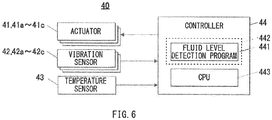
- FIG. 6 is a block diagram illustrating an example of a schematic configuration of the diagnosis system 40.
- the diagnosis system 40 illustrates an example of a fluid level detection apparatus according to at least one embodiment of the invention.
- the diagnosis system 40 may be mounted on a mobile body such as the aircraft 50, and may monitor an amount of a fuel in the fuel tank 52 of the aircraft 50.
- the fuel tank 52 may be disposed in a fuselage 51 of the aircraft 50, and may contain the fuel.
- the fuel tank 52 may be partitioned into a plurality of tank chambers 53.
- the tank chambers 53 each may include a partition wall having a hole that allows inside of one tank chamber 53 and inside of adjacent another tank chamber 53 to be in communication with each other.
- the fuel tank 52 may include a metal or a composite.
- the diagnosis system 40 may include three vibrators or actuators 41 (i.e., actuators 41a to 41c), three vibration sensors 42 (i.e., vibration sensors 42a to 42c), and a controller 44.
- the diagnosis system 40 may include a temperature sensor 43.
- the three actuators 41, the three vibration sensors 42, and the temperature sensor 43 may be provided on each of the tank chambers 53.
- a description is given by referring to only one of the tank chambers 53 provided with the three actuators 41, the three vibration sensors 42, and the temperature sensor 43 that are used for a detection of a fluid level in the relevant tank chamber 53.
- the three actuators 41 each may apply a vibration to the fuel tank 52, or to the tank chamber 53.
- the three actuators 41 may be provided at respective planar positions of the tank chamber 53 that are different from each other, such that the fluctuation of a fluid level 60a of a fuel 60 in the tank chamber 53 is detectable.
- the three actuators 41 may be provided at respective positions that are different from each other within a horizontal plane, orthogonal to a vertical direction, of the tank chamber 53.
- the tank chamber 53 here is in an ordinary state in which the tank chamber 53 is not tilted.
- the first actuator 41a among the three actuators 41 may be disposed at a right upper end of a front outer wall surface 53a of the tank chamber 53
- the second actuator 41b among the three actuators 41 may be disposed at a left upper end of the front outer wall surface 53a of the tank chamber 53.
- the third actuator 41c among the three actuators 41 may be disposed at a middle upper end of a rear outer wall surface 53b of the tank chamber 53.
- positions of the three actuators 41 are not limited to those in the above-described example of the second example embodiment, as long as the positions of the three actuators 41 are different from each other within the horizontal plane of the tank chamber 53 in the ordinary state.
- the number of actuators 41 is not particularly limited, as long as the diagnosis system 40 includes the three actuators 41 disposed at the respective positions that are different from each other within the horizontal plane of the tank chamber 53.
- the three vibration sensors 42 each may detect the vibration wave that propagates through the fuel tank 52, or the tank chamber 53.
- the three vibration sensors 42 each may be the optical fiber sensor that detects the ultrasonic vibration.
- the three vibration sensors 42 may correspond to the respective three actuators 41, and may be disposed at respective positions below the corresponding three actuators 41.
- the first vibration sensor 42a among the three vibration sensors 42 may be disposed at a right lower end of the front outer wall surface 53a of the tank chamber 53, and the second vibration sensor 42b among the three vibration sensors 42 may be disposed at a left lower end of the front outer wall surface 53a of the tank chamber 53. Further, in the example illustrated in FIG. 5B , the third vibration sensor 42c among the three vibration sensors 42 may be disposed at a middle lower end of the rear outer wall surface 53b of the tank chamber 53.
- the positions of the three vibration sensors 42 are not limited to those in the above-described example of the second example embodiment, as long as the three vibration sensors 42 are provided at the respective planar positions of the tank chamber 53 that correspond to the three actuators 41 and that are different from each other.
- the tank chamber 53 here is in the ordinary state.
- the positions of the three vibration sensors 42 are not limited to those in the above-described example of the second example embodiment, as long as the positions of the three vibration sensors 42 are different from each other within the horizontal plane of the tank chamber 53 in the ordinary state. Further, the number of vibration sensors 42 is not particularly limited, as long as the diagnosis system 40 includes the three vibration sensors 42 that correspond to the respective three actuators 41.
- the temperature sensor 43 may be provided at a lower part of the outer wall surface of the fuel tank 52 (or the tank chamber 53), and may measure a temperature of a wall of the tank chamber 53.
- the temperature sensor 43 may indirectly acquire a temperature of the fuel 60 on the basis of the temperature of the wall of the tank chamber 53.
- the controller 44 may be or may include a computer that has elements including a central processing unit (CPU) 443 and a memory (or a storage) 442.
- the controller 44 may control each part of the diagnosis system 40 comprehensively. For example, on the basis of a predetermined program and/or an operation performed by the pilot, the controller 44 may control an operation of each of the three actuators 41 and perform arithmetic processing on a detection signal obtained from each of the three vibration sensors 42, the temperature sensor 43, or both.
- the controller 44 may calculate a height of the fluid level 60a in the fuel tank 52.
- the controller 44 may hold in advance a fluid level detection program 441 in the memory 442.
- the fluid level detection program 441 may allow for execution of a later-described fluid level detection process.
- the fluid level detection program 441 may be supplied from the computer-readable medium provided outside of the controller 44.
- the fluid level detection program 441 may be supplied via the network.
- the memory 442 may serve as the "non-transitory computer-readable medium”.
- the CPU 443 may serve as the "controller”.
- the fluid level detection process may be performed by the diagnosis system 40, and may detect the fluid level 60a in the fuel tank 52 (i.e., in the tank chamber 53) to determine excess and deficiency of the fuel 60.
- FIG. 7 is a flowchart illustrating an example of a flow of the fluid level detection process.
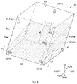
- FIG. 8 is a diagram illustrating a state in which the fluid level 60a of the fuel 60 in the tank chamber 53 fluctuates.
- the fluid level detection process may detect the height of the fluid level 60a of the fuel 60 in the fuel tank 52 (i.e., in the tank chamber 53) and determine whether the fuel 60 is held at an appropriate amount.
- the fluid level detection process may be executed through causing the CPU 443 in the controller 44 to read out the fluid level detection program 441 from the memory 442 and expand the fluid level detection program 441.
- the fluid level detection process may be executed through causing the CPU 443 to execute the fluid level detection program 441 read out from the computer-readable medium provided outside of the controller 44, or causing the CPU 443 to execute the fluid level detection program 441 supplied via the network.
- the controller 44 may first acquire the temperature of the fuel 60 (step T1).
- the controller 44 may acquire the temperature of the fuel 60 in a manner similar to that of step S1 in the fluid level detection process according to the first example embodiment described above.
- the controller 44 may acquire the temperature of the wall of the tank chamber 53 by means of the temperature sensor 43, and may calculate the temperature of the fuel 60 on the basis of the temperature of the wall of the tank chamber 53.
- the temperature of the fuel 60 may be calculated on the basis of a previously-acquired relational expression or a previously-acquired table that represents a relationship between the temperature of the wall of the tank chamber 53 and the temperature of the fuel 60.
- the temperature of the fuel 60 may be determined on the basis of a heat-transfer calculation.
- the acquisition of the temperature of the fuel 60 in step T1 may be performed until the calculation of heights of the fluid level 60a is performed in later-described step T4.
- the controller 44 may drive the three actuators 41 and thereby apply the vibration to the tank chamber 53 (step T2).
- the controller 44 may cause one or more of the three actuators 41 to generate a broadband ultrasonic vibration (such as the Lamb waves) that covers a predetermined frequency range.
- the controller 44 may detect, with the three vibration sensors 42, the vibration waves that are generated by the respective corresponding actuators 41 and propagate through the fuel tank 52 (step T3).
- the three actuators 41 may generate the vibrations having respective frequencies that are different from each other, to allow the three vibration sensors 42 to distinguish between those vibrations generated by the respective corresponding actuators 41.
- the controller 44 may calculate heights of the fluid level 60a of the fuel 60 at the planar positions of the respective three vibration sensors 42, on the basis of the vibrations detected in step T3 (step T4). In some example embodiments, the controller 44 may calculate the heights of the fluid level 60a of the fuel 60 on the basis of the temperature of the fuel 60 acquired in step T1 and the vibration waves detected in step T3.
- the controller 44 may calculate the heights of the fluid level 60a of the fuel 60 at the planar positions, or at the positions within the horizontal plane, of the respective vibration sensors 42 in the tank chamber 53. For example, the controller 44 may calculate the heights of the fluid level 60a at the planar positions of the respective vibration sensors 42 in a manner similar to that in step S4 performed in the fluid level detection process according to the first example embodiment described above.
- the controller 44 may first apply the filtering process to each of the vibration waves detected in step T3 to extract the high frequency component and the low frequency component.
- the high frequency component may have the first predetermined frequency bandwidth that is higher than the first predetermined frequency.
- the low frequency component may have the second predetermined frequency bandwidth that is lower than the second predetermined frequency.
- the predetermined frequencies that serve as thresholds of the respective high frequency component and low frequency component, and/or the predetermined frequency bandwidths that serve as thresholds of the respective high frequency component and low frequency component, may be different from each other between the high frequency component and the low frequency component.
- the predetermined frequencies that serve as the thresholds of the respective high frequency component and low frequency component, and/or the predetermined frequency bandwidths that serve as the thresholds of the respective high frequency component and low frequency component may be the same as each other between the high frequency component and the low frequency component.
- the controller 44 may calculate the nominal value of each of the heights of the fluid level 60a of the fuel 60, on the basis of the high frequency components in the detected vibration waves. Note that a method of calculating the heights of the fluid level 60a, or the nominal value of each of the heights of the fluid level 60a, is not particularly limited.
- data on correlation between waveforms of the respective vibration waves and the heights of the fluid level 60a may be acquired in advance, and the heights of the fluid level 60a or the nominal value of each of the heights of the fluid level 60a may be calculated on the basis of the correlation data.
- the controller 44 may correct the nominal value of each of the heights of the fluid level 60a of the fuel 60, on the basis of the low frequency components in the detected vibration waves. In some example embodiments, the controller 44 may correct the nominal value of each of the heights of the fluid level 60a, on the basis of the temperature of the fuel 60 acquired in step T1 and the low frequency components in the detected vibration waves.
- a method of correcting the nominal value of each of the heights of the fluid level 60a is not particularly limited.
- data on correlation between the temperature of the fuel 60 and the waveforms of the respective vibration waves may be acquired in advance, and the nominal value of each of the heights of the fluid level 60a may be corrected on the basis of the correlation data.
- the above example processes thus allow for calculation of heights h1 to h3 of the fluid level 60a at the planar positions of the respective three vibration sensors 42 as illustrated in FIG. 8 .
- the controller 44 may estimate the height of the fluid level 60a in the ordinary state of the tank chamber 53, on the basis of the three heights h1 to h3 of the fluid level 60a calculated in step T4 (step T5).
- the controller 44 may calculate an estimated height of the fluid level 60a in the ordinary state of the tank chamber 53 in which the tank chamber 53 is not tilted (i.e., the estimated height of the fluid level 60a where no fluctuation occurs in the fluid level 60a), on the basis of the three heights h1 to h3 of the fluid level 60a and a positional relationship between the three vibration sensors 42 corresponding to those heights h1 to h3 of the fluid level 60a.
- the controller 44 may determine whether the estimated height of the fluid level 60a calculated in step T5 is lower than a predetermined threshold (step T6).
- step T6 determines that the estimated height of the fluid level 60a is equal to or higher than the predetermined threshold (step T6: NO)
- the controller 44 may advance the process to later-described step T8.
- One reason is that the fuel 60 satisfies a required amount of fuel.
- step T6 the controller 44 may warn the pilot of the deficiency in the fuel 60 (step T7).
- step T7 One reason is that the fuel 60 does not satisfy the required amount of fuel.
- controller 44 may determine whether to end the fluid level detection process (step T8). If the controller 44 determines not to end the fluid level detection process (step T8: NO), the controller 44 may advance the process to the above-described step T1.
- the controller 44 may repeat the calculation of the estimated height of the fluid level 60a (i.e., the calculation of the amount of fuel) and the determination on the excess and the deficiency of the fuel 60 to thereby monitor the amount of the fuel 60, until the controller 44 determines to end the fluid level detection process.
- step T8 the controller 44 may end the fluid level detection process.
- the controller 44 may determine to end the fluid level detection process when the body of the aircraft 50 is stopped.
- the three actuators 41 may be provided at the respective planar positions, of the fuel tank 52 (i.e., the tank chamber 53) in the ordinary state, that are different from each other.
- the three vibration sensors 42 may be provided at the respective planar positions of the fuel tank 52 (i.e., the tank chamber 53) that correspond to the three actuators 41 and that are different from each other.
- the three heights h1 to h3 of the fluid level 60a at the planar positions of those three vibration sensors 42 may be calculated. Further, the height of the fluid level 60a where no fluctuation occurs in the fluid level 60a may be determined on the basis of the thus-calculated heights h1 to h3 of the fluid level 60a.
- the three actuators 41 may generate the respective vibrations having respective frequencies that are different from each other. With this configuration, it is possible to further ensure that the three vibration sensors 42 are able to distinguish between the vibrations generated by the respective corresponding actuators 41.
- the temperature of the wall of the oil sump or the tank chamber may be measured to determine the temperature of the lubricant or the fuel, and the height(s) of the fluid level may be corrected on the basis of the temperature of the lubricant or the fuel.
- the temperature to be measured and the temperature to be used for the correction are not limited thereto.
- the temperature to be measured and the temperature to be used for the correction each may be any temperature that has a correlation with the temperature of the lubricant or the fuel.
- the nominal value of the height(s) of the fluid level may be corrected on the basis of the low frequency component in the detected vibration wave and the temperature of the lubricant or the fuel. In some example embodiments, the nominal value of the height(s) of the fluid level may be corrected on the basis of only one of the low frequency component in the detected vibration wave, the temperature of the lubricant, and the temperature of the fuel.
- the height(s) of the fluid level of the lubricant or the fuel may be detected on the basis of the actuator(s) and the vibration sensor(s).
- the actuator(s) and the vibration sensor(s) may be used to detect a crack and/or a damage of the wall in addition to the height(s) of the fluid level of the lubricant or the fuel.
- the crack and/or the damage of the wall may be identified on the basis of a manner in which the vibration wave changes.
- the vibrator(s) or actuator(s) and the vibration sensor(s) to correspond to each other while interposing the fluid level from the above and the below suffices. Accordingly, in some example embodiments, the planar positions, or the positions within the horizontal plane, of the actuator(s) and the corresponding vibration sensor(s) in the ordinary state do not necessarily have to be the same as each other. Further, in some example embodiments, the actuator(s) and the vibration sensor(s) may not be provided on a one-on-one basis.
- the first example embodiment describes an example of the detection of the fluid level 30a of the lubricant 30 provided in the oil sump 23 of the transmission assembly 20 of the helicopter 100.
- the second example embodiment describes an example of the detection of the fluid level 60a of the fuel 60 provided in the fuel tank 52 (or the tank chamber 53) of the aircraft 50.
- Embodiments of the invention are not limited to those examples. Any embodiment of the invention is applicable widely to any technique that detects a fluid level of a fluid provided in a container.
- a technique according to the second example embodiment may be applied to the first example embodiment to detect the fluid level of a fuel provided in a fuel tank of the helicopter 100.
- a technique according to the first example embodiment may be applied to the second example embodiment to detect the fluid level of a lubricant provided in a lubricant sump of the aircraft 50.
- a mobile body such as a helicopter monitors, in an indirect fashion, an amount of lubricant provided in a transmission on the basis of a hydraulic pressure in a lubrication system.
- Such an indirect monitoring does not monitor the amount of lubricant in a direct fashion, meaning that it is not possible to immediately detect a leakage of the lubricant if the lubricant is leaked, which in turn can result in dry run.
- one method may be to provide an oil meter or an oil level gauge on an inner side of a case or a container that contains the lubricant, and detect an amount of lubricant or a height of a lubricant level.
- an oil meter or an oil level gauge on an inner side of a case or a container that contains the lubricant, and detect an amount of lubricant or a height of a lubricant level.
- the controllers 14 and 44 respectively illustrated in FIGS. 2 and 6 are each implementable by circuitry including at least one semiconductor integrated circuit such as at least one processor (e.g., a central processing unit (CPU)), at least one application specific integrated circuit (ASIC), and/or at least one field programmable gate array (FPGA).
- processor e.g., a central processing unit (CPU)
- ASIC application specific integrated circuit
- FPGA field programmable gate array
- At least one processor is configurable, by reading instructions from at least one machine readable non-transitory tangible medium, to perform all or a part of functions of the controllers 14 or 44.
- a medium may take many forms, including, but not limited to, any type of magnetic medium such as a hard disk, any type of optical medium such as a CD and a DVD, any type of semiconductor memory (i.e., semiconductor circuit) such as a volatile memory and a non-volatile memory.
- the volatile memory may include a DRAM and a SRAM
- the nonvolatile memory may include a ROM and a NVRAM.
- the ASIC is an integrated circuit (IC) customized to perform
- the FPGA is an integrated circuit designed to be configured after manufacturing in order to perform, all or a part of the functions of the controllers 14 and 44 respectively illustrated in FIGS. 2 and 6 .
Landscapes
- Physics & Mathematics (AREA)
- General Physics & Mathematics (AREA)
- Fluid Mechanics (AREA)
- Thermal Sciences (AREA)
- Acoustics & Sound (AREA)
- Electromagnetism (AREA)
- Engineering & Computer Science (AREA)
- Signal Processing (AREA)
- Measurement Of Levels Of Liquids Or Fluent Solid Materials (AREA)
Abstract
Description
- The present application claims priority from Japanese Patent Application No.
2019-046757 filed on March 14, 2019 2019-152424 filed on August 23, 2019 - The invention relates to a technique that detects a fluid level of a fluid provided in a container.
- A mobile body such as a helicopter indirectly monitors an amount of a lubricant provided in a transmission on the basis of a hydraulic pressure in a lubrication system.
- An aspect of the invention provides a fluid level detection apparatus that includes a vibrator, a vibration sensor, and a controller. The vibrator is configured to apply a vibration to a container that contains a fluid. The vibration sensor is configured to detect a vibration wave that is generated by the vibrator and propagates through the container. The controller is configured to control an operation of the vibrator and perform arithmetic processing on a detection signal obtained from the vibration sensor.
- The vibrator and the vibration sensor are provided on an outer wall surface of the container at respective positions that interpose, from above and below, a fluid level of the fluid provided in the container. The controller is configured to calculate a height of the fluid level, on the basis of the vibration wave detected by the vibration sensor.
- Another aspect of the invention provides a fluid level detection method that includes: providing a vibrator and a vibration sensor on an outer wall surface of a container at respective positions that interpose, from above and below, a fluid level of a fluid provided in the container, in which the vibrator is configured to apply a vibration to the container that contains the fluid, and the vibration sensor is configured to detect a vibration wave that is generated by the vibrator and propagates through the container; and calculating, with a controller, a height of the fluid level, on the basis of the vibration wave detected by the vibration sensor.
- A further aspect of the invention provides a non-transitory computer readable medium containing a fluid level detection program. The fluid level detection program causes, when executed by a computer, the computer to implement a method. The method includes calculating a height of a fluid level of a fluid provided in a container, on the basis of a vibration wave generated by a vibrator and detected by a vibration sensor.
- The vibrator is configured to apply a vibration to the container that contains the fluid. The vibration sensor is configured to detect the vibration wave that is generated by the vibrator and propagates through the container. The vibrator and the vibration sensor are provided on an outer wall surface of the container at respective positions that interpose, from above and below, the fluid level of the fluid provided in the container.
- The accompanying drawings are included to provide a further understanding of the invention, and are incorporated in and constitute a part of this specification. The drawings illustrate embodiments and, together with the specification, serve to explain the principles of the invention.
- FIG. 1
- is a cross-sectional view of a transmission assembly that serves as a target to be diagnosed by a diagnosis system according to one example embodiment of the invention.
- FIG. 2
- is a block diagram illustrating an example of a schematic configuration of the diagnosis system according to one example embodiment.
- FIG. 3
- is a flowchart illustrating an example of a flow of a fluid level detection process according to one example embodiment.
- FIGS. 4A and 4B
- are diagrams each illustrating an example of a principle of detecting a height of a fluid level on the basis of the fluid level detection process according to one example embodiment.
- FIGS. 5A and 5B
- are diagrams each illustrating a fuel tank of an aircraft that serves as a target to be diagnosed by a diagnosis system according to one example embodiment of the invention, in which
- FIG. 5A
- illustrates an example of an external appearance of the aircraft, and
- FIG. 5B
- illustrates an example of a tank chamber of the fuel tank.
- FIG. 6
- is a block diagram illustrating an example of a schematic configuration of the diagnosis system according to one example embodiment.
- FIG. 7
- is a flowchart illustrating an example of a flow of a fluid level detection process according to one example embodiment.
- FIG. 8
- is a diagram illustrating a state in which a fluid level fluctuates in the tank chamber according to one example embodiment.
- In the following, some embodiments of the invention are described in detail with reference to the accompanying drawings. Note that the following description is directed to illustrative examples of the invention and not to be construed as limiting to the invention. Factors including, without limitation, numerical values, shapes, materials, components, positions of the components, and how the components are coupled to each other are illustrative only and not to be construed as limiting to the invention.
- Further, elements in the following example embodiments which are not recited in a most-generic independent claim of the invention are optional and may be provided on an as-needed basis. The drawings are schematic and are not intended to be drawn to scale. Throughout the present specification and the drawings, elements having substantially the same function and configuration are denoted with the same reference numerals to avoid any redundant description.
- A description is given first of an example of a configuration of a
diagnosis system 10 according to a first example embodiment of the invention. -
FIG. 1 is a cross-sectional view of atransmission assembly 20 that serves as a target to be diagnosed by thediagnosis system 10.FIG. 2 is a block diagram illustrating an example of a schematic configuration of thediagnosis system 10. - The
diagnosis system 10 according to the first example embodiment illustrates an example of a fluid level detection apparatus according to at least one embodiment of the invention. Thediagnosis system 10 may be mounted on a mobile body such as ahelicopter 100, and may monitor an amount of a lubricant in thetransmission assembly 20 of thehelicopter 100. In one embodiment, thehelicopter 100 may serve as an "aircraft". - The
transmission assembly 20 may so converting an output of an engine as to have the appropriate number of rotations and an appropriate angle, and may transmit the converted output of the engine to a rotor. Thetransmission assembly 20 may include gears that convert the output of the engine in terms of the number of rotations and the angle, and bearings that support the respective gears. - The
transmission assembly 20 may also include a non-illustrated pump for a fluid 30, for example alubricant 30 that lubricates the gears and the bearings, and acontainer 23, for example anoil sump 23 that contains thelubricant 30, as illustrated inFIG. 1 . Theoil sump 23 may include a metal or a composite. In one embodiment, theoil sump 23 may serve as a "lubricant sump". - Referring to
FIGS. 1 and2 , thediagnosis system 10 includes anactuator 11, avibration sensor 12, and acontroller 14. Thediagnosis system 10 may include atemperature sensor 13. - The
actuator 11 applies a vibration to theoil sump 23. Theactuator 11 may be provided on an upper end of an outer wall surface of theoil sump 23. In one embodiment, theactuator 11 may serve as a "vibrator". - The
vibration sensor 12 detects a vibration wave that is generated by theactuator 11 and propagates through theoil sump 23. In some example embodiments, thevibration sensor 12 may be an optical fiber sensor that detects ultrasonic vibration. Thevibration sensor 12 may be disposed at a position corresponding to theactuator 11. - The
vibration sensor 12 is provided on the outer wall surface of theoil sump 23 at a position that interposes afluid level 30a of thelubricant 30 between the actuator 11 and thevibration sensor 12 from above and below. For example, thevibration sensor 12 may be provided at a lower end, positioned below theactuator 11, of the outer wall surface of theoil sump 23. - The
temperature sensor 13 may measure a temperature of a wall of theoil sump 23. Thetemperature sensor 13 may be provided at a lower part of the outer wall surface of theoil sump 23. Thetemperature sensor 13 may indirectly acquire a temperature of thelubricant 30 on the basis of the temperature of the wall of theoil sump 23. - The
controller 14 may be or may include a computer that has elements including a central processing unit (CPU) 143 and a memory (or a storage) 142. Thecontroller 14 may control each part of thediagnosis system 10 comprehensively. For example, on the basis of a predetermined program and/or an operation performed by a pilot, thecontroller 14 controls an operation of theactuator 11 and performs arithmetic processing on a detection signal obtained from thevibration sensor 12, thetemperature sensor 13, or both. By controlling the operation of theactuator 11 and performing the arithmetic processing, thecontroller 14 calculates a height of thefluid level 30a in theoil sump 23. - The
controller 14 may hold in advance a fluidlevel detection program 141 in thememory 142. The fluidlevel detection program 141 may allow for execution of a later-described fluid level detection process. In some example embodiments, the fluidlevel detection program 141 may be supplied from a computer-readable medium provided outside of thecontroller 14. In some example embodiments, the fluidlevel detection program 141 may be supplied via a network. In one embodiment, thememory 142 may serve as a "non-transitory computer-readable medium". - In one embodiment, the
CPU 143 may serve as a "controller". - A description is given next of an example of the fluid level detection process. The fluid level detection process may be performed by the
diagnosis system 10, and may detect thefluid level 30a in theoil sump 23 to determine excess and deficiency of thelubricant 30. -
FIG. 3 is a flowchart illustrating an example of a flow of the fluid level detection process.FIGS. 4A and 4B are diagrams each illustrating an example of a principle of detecting the height of thefluid level 30a on the basis of the fluid level detection process. - The fluid level detection process according to the first example embodiment may detect the height of the
fluid level 30a of thelubricant 30 in theoil sump 23 and determine whether thelubricant 30 is held at an appropriate amount. The fluid level detection process may be executed through causing theCPU 143 in thecontroller 14 to read out the fluidlevel detection program 141 from thememory 142 and expand the fluidlevel detection program 141. - In some example embodiments, the fluid level detection process may be executed through causing the
CPU 143 to execute the fluidlevel detection program 141 read out from the computer-readable medium provided outside of thecontroller 14, or causing theCPU 143 to execute the fluidlevel detection program 141 supplied via the network. - Referring to
FIG. 3 , upon execution of the fluid level detection process, thecontroller 14 may first acquire the temperature of the lubricant 30 (step S1). For example, thecontroller 14 may acquire the temperature of the wall of theoil sump 23 by means of thetemperature sensor 13, and may calculate the temperature of thelubricant 30 on the basis of the temperature of the wall of theoil sump 23. - For example, the temperature of the
lubricant 30 may be calculated on the basis of a previously-acquired relational expression or a previously-acquired table that represents a relationship between the temperature of the wall of theoil sump 23 and the temperature of thelubricant 30. - Alternatively, the temperature of the
lubricant 30 may be determined on the basis of a heat-transfer calculation. - In some example embodiments, the acquisition of the temperature of the
lubricant 30 in step S1 may be performed until the calculation of the height of thefluid level 30a is performed in later-described step S4. - Thereafter, the
controller 14 may drive theactuator 11 and thereby applies the vibration to the oil sump 23 (step S2). In some example embodiments, thecontroller 14 may cause theactuator 11 to generate a broadband ultrasonic vibration (such as Lamb waves) that covers a predetermined frequency range. - Thereafter, the
controller 14 detects, with thevibration sensor 12, the vibration wave that is generated by theactuator 11 and propagates through the oil sump 23 (step S3). - Thereafter, the
controller 14 calculates the height of thefluid level 30a of thelubricant 30 on the basis of the vibration wave detected in step S3 (step S4). In some example embodiments, thecontroller 14 may calculate the height of thefluid level 30a of thelubricant 30 on the basis of the temperature of thelubricant 30 acquired in step S1 and the vibration wave detected in step S3. - In one example, in step S4, the
controller 14 may first apply a filtering process to the vibration wave detected in step S3 to extract a high frequency component and a low frequency component. The high frequency component may have a first predetermined frequency bandwidth that is higher than a first predetermined frequency. The low frequency component may have a second predetermined frequency bandwidth that is lower than a second predetermined frequency. - The predetermined frequencies that serve as thresholds of the respective high frequency component and low frequency component, and/or the predetermined frequency bandwidths that serve as thresholds of the respective high frequency component and low frequency component, may be different from each other between the high frequency component and the low frequency component.
- Alternatively, the predetermined frequencies that serve as the thresholds of the respective high frequency component and low frequency component, and/or the predetermined frequency bandwidths that serve as the thresholds of the respective high frequency component and low frequency component, may be the same as each other between the high frequency component and the low frequency component.
- Thereafter, the
controller 14 may calculate a nominal value of the height of thefluid level 30a of thelubricant 30, on the basis of the high frequency component in the detected vibration wave. The vibration waveform that propagates through theoil sump 23 is more attenuated when an amount of lubricant is large, and is less attenuated when the amount of lubricant is small, as illustrated inFIGS. 4A and 4B . - Further, in general, the vibration at a high frequency is easily attenuated and is high in directionality as well, making it easier to detect the
fluid level 30a. Accordingly, thecontroller 14 may determine a rough position of thefluid level 30a of thelubricant 30 as the nominal value, on the basis of the high frequency component in the detected vibration wave. - Note that a method of calculating the height of the
fluid level 30a, or the nominal value of the height of thefluid level 30a, is not particularly limited. For example, data on correlation between a waveform of the vibration wave and the height of thefluid level 30a may be acquired in advance, and the height of thefluid level 30a or the nominal value of the height of thefluid level 30a may be calculated on the basis of the correlation data. - Thereafter, the
controller 14 may correct the nominal value of the height of thefluid level 30a, on the basis of the low frequency component in the detected vibration wave. In some example embodiments, thecontroller 14 may correct the nominal value of the height of thefluid level 30a, on the basis of the temperature of thelubricant 30 acquired in step S1 and the low frequency component in the detected vibration wave. Thelubricant 30 causes a change in its viscosity depending on the temperature and thus causes a change in ease of the propagation of the vibration wave. - In addition, the vibration at a low frequency is less attenuated but is more susceptible to a temperature as compared with the vibration at the high frequency, making it possible to obtain more accurate data on an influence of the temperature of the
lubricant 30 from the low frequency component. Accordingly, thecontroller 14 may compensate the nominal value of the height of thefluid level 30a by an amount corresponding to the change in the temperature of thelubricant 30, on the basis of the low frequency component in the vibration wave and the temperature of thelubricant 30. - Note that a method of correcting the nominal value of the height of the
fluid level 30a is not particularly limited. For example, data on correlation between the temperature of thelubricant 30 and the waveform of the vibration wave may be acquired in advance, and the nominal value of the height of thefluid level 30a may be corrected on the basis of the correlation data. - The above example processes make it possible to calculate, more accurately, the height of the
fluid level 30a in which the influence of the temperature of thelubricant 30 has been taken into consideration.
Thereafter, thecontroller 14 may determine whether the height of thefluid level 30a calculated in step S4 is lower than a predetermined threshold (step S5). For example, the threshold may be an upper limit, at which dry run occurs, of a range of the amount of lubricant. - If the
controller 14 determines that the height of thefluid level 30a is equal to or higher than the predetermined threshold (step S5: NO), thecontroller 14 may advance the process to later-described step S7. One reason is that thelubricant 30 satisfies a required amount of lubricant. - If the
controller 14 determines that the height of thefluid level 30a is lower than the predetermined threshold (step S5: YES), thecontroller 14 may warn the pilot of the deficiency in the lubricant 30 (step S6). One reason is that thelubricant 30 does not satisfy the required amount of lubricant. - Thereafter, the
controller 14 may determine whether to end the fluid level detection process (step S7). If thecontroller 14 determines not to end the fluid level detection process (step S7: NO), thecontroller 14 may advance the process to the above-described step S1. - In this case, the
controller 14 may repeat the calculation of the height of thefluid level 30a (i.e., the calculation of the amount of lubricant) and the determination on the excess and the deficiency of thelubricant 30 to thereby monitor the amount of thelubricant 30, until thecontroller 14 determines to end the fluid level detection process. - If the
controller 14 determines to end the fluid level detection process (step S7: YES), thecontroller 14 may end the fluid level detection process. For example, thecontroller 14 may determine to end the fluid level detection process when a body of thehelicopter 100 is stopped. - According to the first example embodiment of the invention, the
actuator 11 and thevibration sensor 12 are provided on the outer wall surface of theoil sump 23 at the respective positions that interpose, from above and below, thefluid level 30a of thelubricant 30 provided in theoil sump 23. The height of thefluid level 30a is calculated on the basis of the vibration wave that is generated by theactuator 11 and detected by thevibration sensor 12. The vibration wave may be the ultrasonic vibration. - With this configuration, it is possible to suitably detect the height of the
fluid level 30a from the outside of theoil sump 23 that contains thelubricant 30. This configuration in turn allows theactuator 11 and thevibration sensor 12 to be in non-contact with thelubricant 30. Hence, it is possible to improve maintenance of thetransmission assembly 20. - In some example embodiments, the height of the
fluid level 30a may be corrected on the basis of the temperature of thelubricant 30 actually measured by thetemperature sensor 13. Hence, it is possible to calculate, more accurately, the height of thefluid level 30a in which the influence of the temperature of thelubricant 30 has been taken into consideration. - In some example embodiments, the nominal value of the height of the
fluid level 30a may be calculated on the basis of the high frequency component in the vibration wave detected by thevibration sensor 12, and the nominal value may be corrected on the basis of the low frequency component in the detected vibration wave. With this configuration, a rough position of thefluid level 30a is detected on the basis of the high frequency component, and the position is corrected on the basis of the low frequency component that is more susceptible to the influence of the temperature. - Hence, it is possible to calculate, even more accurately, the height of the
fluid level 30a in which the influence of the temperature of thelubricant 30 has been taken into consideration. - A description is given next of an example of a
diagnosis system 40 according to a second example embodiment of the invention. Note that the same or equivalent elements as those of the foregoing first example embodiment are denoted with the same reference numerals, and will not be described in detail. Thediagnosis system 40 according to the second example embodiment differs from thediagnosis system 10 according to the first embodiment, in that thediagnosis system 40 is able to detect a fluctuation in a fluid level. - A description is given first of an example of a configuration of the
diagnosis system 40 according to the second example embodiment of the invention. -
FIGS. 5A and 5B are diagrams each illustrating a container or afuel tank 52 of anaircraft 50 that serves as a target to be diagnosed by thediagnosis system 40, in whichFIG. 5A illustrates an example of an external appearance of theaircraft 50, andFIG. 5B schematically illustrates an example of atank chamber 53 of thefuel tank 52.FIG. 6 is a block diagram illustrating an example of a schematic configuration of thediagnosis system 40. - The
diagnosis system 40 according to the second example embodiment illustrates an example of a fluid level detection apparatus according to at least one embodiment of the invention. Thediagnosis system 40 may be mounted on a mobile body such as theaircraft 50, and may monitor an amount of a fuel in thefuel tank 52 of theaircraft 50. - Referring to
FIG. 5A , thefuel tank 52 may be disposed in afuselage 51 of theaircraft 50, and may contain the fuel. Thefuel tank 52 may be partitioned into a plurality oftank chambers 53. Thetank chambers 53 each may include a partition wall having a hole that allows inside of onetank chamber 53 and inside of adjacent anothertank chamber 53 to be in communication with each other. Thefuel tank 52 may include a metal or a composite. - Referring to
FIGS. 5B and6 , thediagnosis system 40 may include three vibrators or actuators 41 (i.e., actuators 41a to 41c), three vibration sensors 42 (i.e., vibration sensors 42a to 42c), and acontroller 44. Thediagnosis system 40 may include atemperature sensor 43. - The three actuators 41, the three vibration sensors 42, and the
temperature sensor 43 may be provided on each of thetank chambers 53. In the following, for description purpose, a description is given by referring to only one of thetank chambers 53 provided with the three actuators 41, the three vibration sensors 42, and thetemperature sensor 43 that are used for a detection of a fluid level in therelevant tank chamber 53. - The three actuators 41 each may apply a vibration to the
fuel tank 52, or to thetank chamber 53. The three actuators 41 may be provided at respective planar positions of thetank chamber 53 that are different from each other, such that the fluctuation of afluid level 60a of afuel 60 in thetank chamber 53 is detectable. For example, the three actuators 41 may be provided at respective positions that are different from each other within a horizontal plane, orthogonal to a vertical direction, of thetank chamber 53. - The
tank chamber 53 here is in an ordinary state in which thetank chamber 53 is not tilted. In an example illustrated inFIG. 5B , the first actuator 41a among the three actuators 41 may be disposed at a right upper end of a frontouter wall surface 53a of thetank chamber 53, and the second actuator 41b among the three actuators 41 may be disposed at a left upper end of the frontouter wall surface 53a of thetank chamber 53. - Further, in the example illustrated in
FIG. 5B , the third actuator 41c among the three actuators 41 may be disposed at a middle upper end of a rearouter wall surface 53b of thetank chamber 53. - Note that the positions of the three actuators 41 are not limited to those in the above-described example of the second example embodiment, as long as the positions of the three actuators 41 are different from each other within the horizontal plane of the
tank chamber 53 in the ordinary state. - Further, the number of actuators 41 is not particularly limited, as long as the
diagnosis system 40 includes the three actuators 41 disposed at the respective positions that are different from each other within the horizontal plane of thetank chamber 53. - The three vibration sensors 42 each may detect the vibration wave that propagates through the
fuel tank 52, or thetank chamber 53. In some example embodiments, the three vibration sensors 42 each may be the optical fiber sensor that detects the ultrasonic vibration. The three vibration sensors 42 may correspond to the respective three actuators 41, and may be disposed at respective positions below the corresponding three actuators 41. - In an example illustrated in
FIG. 5B , the first vibration sensor 42a among the three vibration sensors 42 may be disposed at a right lower end of the frontouter wall surface 53a of thetank chamber 53, and the second vibration sensor 42b among the three vibration sensors 42 may be disposed at a left lower end of the frontouter wall surface 53a of thetank chamber 53. Further, in the example illustrated inFIG. 5B , the third vibration sensor 42c among the three vibration sensors 42 may be disposed at a middle lower end of the rearouter wall surface 53b of thetank chamber 53. - Note that the positions of the three vibration sensors 42 are not limited to those in the above-described example of the second example embodiment, as long as the three vibration sensors 42 are provided at the respective planar positions of the
tank chamber 53 that correspond to the three actuators 41 and that are different from each other. Thetank chamber 53 here is in the ordinary state. - In other words, the positions of the three vibration sensors 42 are not limited to those in the above-described example of the second example embodiment, as long as the positions of the three vibration sensors 42 are different from each other within the horizontal plane of the
tank chamber 53 in the ordinary state. Further, the number of vibration sensors 42 is not particularly limited, as long as thediagnosis system 40 includes the three vibration sensors 42 that correspond to the respective three actuators 41. - The
temperature sensor 43 may be provided at a lower part of the outer wall surface of the fuel tank 52 (or the tank chamber 53), and may measure a temperature of a wall of thetank chamber 53. Thetemperature sensor 43 may indirectly acquire a temperature of thefuel 60 on the basis of the temperature of the wall of thetank chamber 53. - The
controller 44 may be or may include a computer that has elements including a central processing unit (CPU) 443 and a memory (or a storage) 442. Thecontroller 44 may control each part of thediagnosis system 40 comprehensively. For example, on the basis of a predetermined program and/or an operation performed by the pilot, thecontroller 44 may control an operation of each of the three actuators 41 and perform arithmetic processing on a detection signal obtained from each of the three vibration sensors 42, thetemperature sensor 43, or both. - By controlling the operation of each of the actuators 41 and performing the arithmetic processing, the
controller 44 may calculate a height of thefluid level 60a in thefuel tank 52. - The
controller 44 may hold in advance a fluidlevel detection program 441 in thememory 442. The fluidlevel detection program 441 may allow for execution of a later-described fluid level detection process. In some example embodiments, the fluidlevel detection program 441 may be supplied from the computer-readable medium provided outside of thecontroller 44. In some example embodiments, the fluidlevel detection program 441 may be supplied via the network. - In one embodiment, the
memory 442 may serve as the "non-transitory computer-readable medium". - In one embodiment, the
CPU 443 may serve as the "controller". - A description is given next of an example of the fluid level detection process. The fluid level detection process may be performed by the
diagnosis system 40, and may detect thefluid level 60a in the fuel tank 52 (i.e., in the tank chamber 53) to determine excess and deficiency of thefuel 60. -
FIG. 7 is a flowchart illustrating an example of a flow of the fluid level detection process.FIG. 8 is a diagram illustrating a state in which thefluid level 60a of thefuel 60 in thetank chamber 53 fluctuates. - The fluid level detection process according to the second example embodiment may detect the height of the
fluid level 60a of thefuel 60 in the fuel tank 52 (i.e., in the tank chamber 53) and determine whether thefuel 60 is held at an appropriate amount. The fluid level detection process may be executed through causing theCPU 443 in thecontroller 44 to read out the fluidlevel detection program 441 from thememory 442 and expand the fluidlevel detection program 441. - In some example embodiments, the fluid level detection process may be executed through causing the
CPU 443 to execute the fluidlevel detection program 441 read out from the computer-readable medium provided outside of thecontroller 44, or causing theCPU 443 to execute the fluidlevel detection program 441 supplied via the network. - Referring to
FIG. 7 , upon execution of the fluid level detection process, thecontroller 44 may first acquire the temperature of the fuel 60 (step T1). - In one example, the
controller 44 may acquire the temperature of thefuel 60 in a manner similar to that of step S1 in the fluid level detection process according to the first example embodiment described above. For example, thecontroller 44 may acquire the temperature of the wall of thetank chamber 53 by means of thetemperature sensor 43, and may calculate the temperature of thefuel 60 on the basis of the temperature of the wall of thetank chamber 53. - For example, the temperature of the
fuel 60 may be calculated on the basis of a previously-acquired relational expression or a previously-acquired table that represents a relationship between the temperature of the wall of thetank chamber 53 and the temperature of thefuel 60. Alternatively, the temperature of thefuel 60 may be determined on the basis of a heat-transfer calculation. - In some example embodiments, the acquisition of the temperature of the
fuel 60 in step T1 may be performed until the calculation of heights of thefluid level 60a is performed in later-described step T4. - Thereafter, the
controller 44 may drive the three actuators 41 and thereby apply the vibration to the tank chamber 53 (step T2). In some example embodiments, thecontroller 44 may cause one or more of the three actuators 41 to generate a broadband ultrasonic vibration (such as the Lamb waves) that covers a predetermined frequency range. - Thereafter, the
controller 44 may detect, with the three vibration sensors 42, the vibration waves that are generated by the respective corresponding actuators 41 and propagate through the fuel tank 52 (step T3). - In some example embodiments, the three actuators 41 may generate the vibrations having respective frequencies that are different from each other, to allow the three vibration sensors 42 to distinguish between those vibrations generated by the respective corresponding actuators 41.
- Thereafter, the
controller 44 may calculate heights of thefluid level 60a of thefuel 60 at the planar positions of the respective three vibration sensors 42, on the basis of the vibrations detected in step T3 (step T4). In some example embodiments, thecontroller 44 may calculate the heights of thefluid level 60a of thefuel 60 on the basis of the temperature of thefuel 60 acquired in step T1 and the vibration waves detected in step T3. - In step T4, the
controller 44 may calculate the heights of thefluid level 60a of thefuel 60 at the planar positions, or at the positions within the horizontal plane, of the respective vibration sensors 42 in thetank chamber 53. For example, thecontroller 44 may calculate the heights of thefluid level 60a at the planar positions of the respective vibration sensors 42 in a manner similar to that in step S4 performed in the fluid level detection process according to the first example embodiment described above. - In one example, in step T4, the
controller 44 may first apply the filtering process to each of the vibration waves detected in step T3 to extract the high frequency component and the low frequency component. The high frequency component may have the first predetermined frequency bandwidth that is higher than the first predetermined frequency. - The low frequency component may have the second predetermined frequency bandwidth that is lower than the second predetermined frequency. The predetermined frequencies that serve as thresholds of the respective high frequency component and low frequency component, and/or the predetermined frequency bandwidths that serve as thresholds of the respective high frequency component and low frequency component, may be different from each other between the high frequency component and the low frequency component.
- Alternatively, the predetermined frequencies that serve as the thresholds of the respective high frequency component and low frequency component, and/or the predetermined frequency bandwidths that serve as the thresholds of the respective high frequency component and low frequency component, may be the same as each other between the high frequency component and the low frequency component.
- Thereafter, the
controller 44 may calculate the nominal value of each of the heights of thefluid level 60a of thefuel 60, on the basis of the high frequency components in the detected vibration waves. Note that a method of calculating the heights of thefluid level 60a, or the nominal value of each of the heights of thefluid level 60a, is not particularly limited. - For example, data on correlation between waveforms of the respective vibration waves and the heights of the
fluid level 60a may be acquired in advance, and the heights of thefluid level 60a or the nominal value of each of the heights of thefluid level 60a may be calculated on the basis of the correlation data. - Thereafter, the
controller 44 may correct the nominal value of each of the heights of thefluid level 60a of thefuel 60, on the basis of the low frequency components in the detected vibration waves. In some example embodiments, thecontroller 44 may correct the nominal value of each of the heights of thefluid level 60a, on the basis of the temperature of thefuel 60 acquired in step T1 and the low frequency components in the detected vibration waves. - Note that a method of correcting the nominal value of each of the heights of the
fluid level 60a is not particularly limited. For example, data on correlation between the temperature of thefuel 60 and the waveforms of the respective vibration waves may be acquired in advance, and the nominal value of each of the heights of thefluid level 60a may be corrected on the basis of the correlation data. - The above example processes thus allow for calculation of heights h1 to h3 of the
fluid level 60a at the planar positions of the respective three vibration sensors 42 as illustrated inFIG. 8 . By determining a difference between the heights h1 to h3, it is possible to detect a fluctuation of thefluid level 60a caused by, for example, a tilt of thetank chamber 53 or acceleration/deceleration of a body of theaircraft 50. - Thereafter, the
controller 44 may estimate the height of thefluid level 60a in the ordinary state of thetank chamber 53, on the basis of the three heights h1 to h3 of thefluid level 60a calculated in step T4 (step T5). - For example, the
controller 44 may calculate an estimated height of thefluid level 60a in the ordinary state of thetank chamber 53 in which thetank chamber 53 is not tilted (i.e., the estimated height of thefluid level 60a where no fluctuation occurs in thefluid level 60a), on the basis of the three heights h1 to h3 of thefluid level 60a and a positional relationship between the three vibration sensors 42 corresponding to those heights h1 to h3 of thefluid level 60a. - Thereafter, the
controller 44 may determine whether the estimated height of thefluid level 60a calculated in step T5 is lower than a predetermined threshold (step T6). - If the
controller 44 determines that the estimated height of thefluid level 60a is equal to or higher than the predetermined threshold (step T6: NO), thecontroller 44 may advance the process to later-described step T8. One reason is that thefuel 60 satisfies a required amount of fuel. - If the
controller 44 determines that the estimated height of thefluid level 60a is lower than the predetermined threshold (step T6: YES), thecontroller 44 may warn the pilot of the deficiency in the fuel 60 (step T7). One reason is that thefuel 60 does not satisfy the required amount of fuel. - Thereafter, the
controller 44 may determine whether to end the fluid level detection process (step T8). If thecontroller 44 determines not to end the fluid level detection process (step T8: NO), thecontroller 44 may advance the process to the above-described step T1. - In this case, the
controller 44 may repeat the calculation of the estimated height of thefluid level 60a (i.e., the calculation of the amount of fuel) and the determination on the excess and the deficiency of thefuel 60 to thereby monitor the amount of thefuel 60, until thecontroller 44 determines to end the fluid level detection process. - If the
controller 44 determines to end the fluid level detection process (step T8: YES), thecontroller 44 may end the fluid level detection process. For example, thecontroller 44 may determine to end the fluid level detection process when the body of theaircraft 50 is stopped. - According to the second example embodiment of the invention, it is possible to achieve effects that are similar to those of the first example embodiment described above.
- In addition, in the second example embodiment, the three actuators 41 may be provided at the respective planar positions, of the fuel tank 52 (i.e., the tank chamber 53) in the ordinary state, that are different from each other. Further, the three vibration sensors 42 may be provided at the respective planar positions of the fuel tank 52 (i.e., the tank chamber 53) that correspond to the three actuators 41 and that are different from each other.
- With this configuration, on the basis of the vibration waves detected by the three vibration sensors 42, the three heights h1 to h3 of the
fluid level 60a at the planar positions of those three vibration sensors 42 may be calculated. Further, the height of thefluid level 60a where no fluctuation occurs in thefluid level 60a may be determined on the basis of the thus-calculated heights h1 to h3 of thefluid level 60a. - Hence, it is possible to detect the amount of the
fuel 60 more accurately even in a case where thefluid level 30a fluctuates due to bank of the body of theaircraft 50, acceleration or deceleration of the body of theaircraft 50, or any other factor that causes the fluctuation in thefluid level 60a. This in turn makes it possible to detect a remaining amount of thefuel 60 more accurately and to improve safety upon operation accordingly. - In addition, in some example embodiments, the three actuators 41 may generate the respective vibrations having respective frequencies that are different from each other. With this configuration, it is possible to further ensure that the three vibration sensors 42 are able to distinguish between the vibrations generated by the respective corresponding actuators 41.
- Although some example embodiments of the invention have been described in the foregoing, the invention is by no means limited to the first and the second example embodiments described above. Various changes and modifications may be made to any embodiment without departing from the scope of the invention.
- For example, in the foregoing example embodiments, the temperature of the wall of the oil sump or the tank chamber may be measured to determine the temperature of the lubricant or the fuel, and the height(s) of the fluid level may be corrected on the basis of the temperature of the lubricant or the fuel.
- However, the temperature to be measured and the temperature to be used for the correction are not limited thereto. In some example embodiments, the temperature to be measured and the temperature to be used for the correction each may be any temperature that has a correlation with the temperature of the lubricant or the fuel.
- In the foregoing example embodiments, the nominal value of the height(s) of the fluid level may be corrected on the basis of the low frequency component in the detected vibration wave and the temperature of the lubricant or the fuel. In some example embodiments, the nominal value of the height(s) of the fluid level may be corrected on the basis of only one of the low frequency component in the detected vibration wave, the temperature of the lubricant, and the temperature of the fuel.
- In the foregoing example embodiments, the height(s) of the fluid level of the lubricant or the fuel may be detected on the basis of the actuator(s) and the vibration sensor(s). In some example embodiments, the actuator(s) and the vibration sensor(s) may be used to detect a crack and/or a damage of the wall in addition to the height(s) of the fluid level of the lubricant or the fuel. For example, the crack and/or the damage of the wall may be identified on the basis of a manner in which the vibration wave changes.
- With this configuration, it is possible to determine a correlation between the damage or the like of a container and a change in a fluid level in the container. Hence, it is possible to identify a cause of a decrease in the fluid level promptly, in an example case where the container is damaged and the fluid in the container is leaked.
- In the foregoing example embodiments, causing the vibrator(s) or actuator(s) and the vibration sensor(s) to correspond to each other while interposing the fluid level from the above and the below suffices. Accordingly, in some example embodiments, the planar positions, or the positions within the horizontal plane, of the actuator(s) and the corresponding vibration sensor(s) in the ordinary state do not necessarily have to be the same as each other. Further, in some example embodiments, the actuator(s) and the vibration sensor(s) may not be provided on a one-on-one basis.
- The first example embodiment describes an example of the detection of the
fluid level 30a of thelubricant 30 provided in theoil sump 23 of thetransmission assembly 20 of thehelicopter 100. The second example embodiment describes an example of the detection of thefluid level 60a of thefuel 60 provided in the fuel tank 52 (or the tank chamber 53) of theaircraft 50. Embodiments of the invention, however, are not limited to those examples. Any embodiment of the invention is applicable widely to any technique that detects a fluid level of a fluid provided in a container. - The invention encompasses any possible combination of some or all of the various embodiments and the modifications described herein and incorporated herein. For example, a technique according to the second example embodiment may be applied to the first example embodiment to detect the fluid level of a fuel provided in a fuel tank of the
helicopter 100. For example, a technique according to the first example embodiment may be applied to the second example embodiment to detect the fluid level of a lubricant provided in a lubricant sump of theaircraft 50. - A mobile body such as a helicopter monitors, in an indirect fashion, an amount of lubricant provided in a transmission on the basis of a hydraulic pressure in a lubrication system. Such an indirect monitoring does not monitor the amount of lubricant in a direct fashion, meaning that it is not possible to immediately detect a leakage of the lubricant if the lubricant is leaked, which in turn can result in dry run.
- To address such a concern, one method may be to provide an oil meter or an oil level gauge on an inner side of a case or a container that contains the lubricant, and detect an amount of lubricant or a height of a lubricant level. For example, reference is made to Japanese Unexamined Patent Application Publication
JP 2008-014 267 A - Providing the measuring instrument on the inner side of the container, however, involves many difficulties, including modification of a transmission and time-consuming inspection and replacement.
- It is desirable to accurately detect an amount of lubricant (fuel) or a height of a lubricant level (fuel level) from the outside of a container. At least one embodiment makes it possible to detect a height of a fluid level appropriately from the outside of a container that contains a fluid. The
controllers FIGS. 2 and6 are each implementable by circuitry including at least one semiconductor integrated circuit such as at least one processor (e.g., a central processing unit (CPU)), at least one application specific integrated circuit (ASIC), and/or at least one field programmable gate array (FPGA). - At least one processor is configurable, by reading instructions from at least one machine readable non-transitory tangible medium, to perform all or a part of functions of the
controllers - The volatile memory may include a DRAM and a SRAM, and the nonvolatile memory may include a ROM and a NVRAM. The ASIC is an integrated circuit (IC) customized to perform, and the FPGA is an integrated circuit designed to be configured after manufacturing in order to perform, all or a part of the functions of the
controllers FIGS. 2 and6 . -
- 10
- diagnosis system
- 11
- actuator (vibrator)
- 12
- vibration sensor
- 13
- temperature sensor
- 14
- controller
- 20
- transmission assembly
- 23
- container, lubricant sump
- 30
- fluid, lubricant
- 30a
- fluid level
- 41
- actuator (vibrator)
- 41 a
- actuator (vibrator)
- 41b
- actuator (vibrator)
- 41 c
- actuator (vibrator)
- 42
- vibration sensor
- 42a
- vibration sensor
- 42b
- vibration sensor
- 42c
- vibration sensor
- 43
- temperature sensor
- 44
- controller
- 50
- aircraft
- 51
- fuselage
- 52
- fuel tank
- 53
- tank chamber
- 53a
- front outer wall surface
- 53b
- a rear outer wall surface
- 60
- fuel
- 60a
- fluid level
- 100
- helicopter, aircraft
- 141
- fluid level detection program
- 142
- memory, storage
- 143
- CPU
- 441
- fluid level detection program
- 442
- memory, storage
- 443
- CPU
Claims (8)
- A fluid level detection apparatus (10) comprising:- a vibrator (11) configured to apply a vibration to a container (23) that contains a fluid;- a vibration sensor (12) configured to detect a vibration wave that is generated by the vibrator (11) and propagates through the container (23); and- a controller (14) configured to control an operation of the vibrator (11) and perform arithmetic processing on a detection signal obtained from the vibration sensor (12),- the vibrator (11) and the vibration sensor (12) being provided on an outer wall surface of the container (23) at respective positions that interpose, from above and below, a fluid level (30a) of the fluid (30) provided in the container (23),- the controller (14) being configured to calculate a height of the fluid level, on a basis of the vibration wave detected by the vibration sensor (12).
- The fluid level detection apparatus (10) according to claim 1, further comprising a temperature sensor (13) configured to measure a temperature of the fluid (30) provided in the container (23), wherein the controller (14) is configured to correct the height of the calculated fluid level on a basis of the temperature measured by the temperature sensor (13).
- The fluid level detection apparatus (10) according to claim 1 or 2, wherein the controller (14) is configured to cause the vibrator (11) to generate, as the vibration, an ultrasonic vibration that covers a predetermined frequency range, and
wherein the controller (14) is configured to calculate, as the height of the fluid level (30a), a nominal value of the height of the fluid level on a basis of a high frequency component in the vibration wave detected by the vibration sensor (12), and correct the nominal value on a basis of a low frequency component in the vibration wave detected by the vibration sensor (12), the high frequency component being higher than a first predetermined frequency, the low frequency component being lower than a second predetermined frequency. - The fluid level detection apparatus (10)
according to any one of claims 1 to 3,
wherein the vibrator (41) comprises at least three vibrators (41a, 41b, 41c) provided at respective positions that are different from each other within a horizontal plane of the container (52) that is in an ordinary state, the ordinary state being a state in which the container (52) is not tilted, and wherein the vibration sensor (42) comprises at least three vibration sensors (42a, 42b, 42c) provided at respective positions that correspond to the at least three vibrators (41a, 41b, 41c) and that are different from each other within the horizontal plane of the container (52) that is in the ordinary state. - The fluid level detection apparatus (40) according to claim 4,
wherein the controller (44) is configured to cause the at least three vibrators (11) to apply, to the container (52), the vibrations at frequencies that are different from each other. - The fluid level detection apparatus (40)
according to any one of claims 1 to 5,
wherein the fluid level detection apparatus (40) is mounted on an aircraft (50, 100) and configured to detect the fluid level (30a) of a lubricant (30) serving as the fluid and provided in a lubricant sump (23) of the aircraft (100), or detect the fluid level (60a) of a fuel (60) serving as the fluid and provided in a fuel tank (52) of the aircraft (50, 100). - A fluid level detection method comprising:- providing a vibrator (11, 41) and a vibration sensor (12, 42) on an outer wall surface of a container (23, 52) at respective positions that interpose, from above and below, a fluid level of a fluid provided in the container, the vibrator (11, 41) being configured to apply a vibration to the container (23, 52) that contains the fluid (30, 60), the vibration sensor (12, 42) being configured to detect a vibration wave that is generated by the vibrator (11, 41) and propagates through the container (23, 52); and- calculating, with a controller (14, 44), a height of the fluid level (30a, 60a), on a basis of the vibration wave detected by the vibration sensor (12, 42).
- A non-transitory computer readable medium containing a fluid level detection program, the fluid level detection program (141, 441) causing, when executed by a computer, the computer to implement a method, the method comprising- calculating a height of a fluid level (30a, 60a) of a fluid (30, 60) provided in a container (23, 52), on a basis of a vibration wave generated by a vibrator (11, 41) and detected by a vibration sensor (12, 42), the vibrator (11,41) being configured to apply a vibration to the container (23, 52) that contains the fluid (30, 60), the vibration sensor (12, 42) being configured to detect the vibration wave that is generated by the vibrator (11, 41) and propagates through the container (23, 52), the vibrator (11, 41) and the vibration sensor (12, 42) being provided on an outer wall surface of the container (23, 52) at respective positions that interpose, from above and below, the fluid level (30a, 60a) of the fluid (30, 60) provided in the container (23, 52).
Applications Claiming Priority (2)
| Application Number | Priority Date | Filing Date | Title |
|---|---|---|---|
| JP2019046757 | 2019-03-14 | ||
| JP2019152424A JP7372781B2 (en) | 2019-03-14 | 2019-08-23 | Liquid level detection device, liquid level detection method, and liquid level detection program |
Publications (2)
| Publication Number | Publication Date |
|---|---|
| EP3708974A1 true EP3708974A1 (en) | 2020-09-16 |
| EP3708974B1 EP3708974B1 (en) | 2023-06-14 |
Family
ID=69104262
Family Applications (1)
| Application Number | Title | Priority Date | Filing Date |
|---|---|---|---|
| EP20150007.1A Active EP3708974B1 (en) | 2019-03-14 | 2020-01-02 | Fluid level detection apparatus, fluid level detection method, and computer-readable medium containing fluid level detection program |
Country Status (2)
| Country | Link |
|---|---|
| US (1) | US11385094B2 (en) |
| EP (1) | EP3708974B1 (en) |
Cited By (2)
| Publication number | Priority date | Publication date | Assignee | Title |
|---|---|---|---|---|
| CN113720421A (en) * | 2021-09-22 | 2021-11-30 | 北京锐达仪表有限公司 | Vibration wave layered interface measuring device and measuring method |
| EP4269958A1 (en) * | 2022-04-28 | 2023-11-01 | Simmonds Precision Products, Inc. | Guided wave liquid level measurement systems and methods |
Families Citing this family (1)
| Publication number | Priority date | Publication date | Assignee | Title |
|---|---|---|---|---|
| US11566936B1 (en) | 2016-02-12 | 2023-01-31 | Munters Corporation | Method and apparatus to non-intrusively measure the weight of loose bulk material within a rigid containing structure |
Citations (5)
| Publication number | Priority date | Publication date | Assignee | Title |
|---|---|---|---|---|
| US6631639B1 (en) * | 2001-09-07 | 2003-10-14 | Cosense, Inc | System and method of non-invasive discreet, continuous and multi-point level liquid sensing using flexural waves |
| JP2008014267A (en) | 2006-07-07 | 2008-01-24 | Nissan Motor Co Ltd | Fuel level detector |
| DE102010062108A1 (en) * | 2010-11-29 | 2012-05-31 | Robert Bosch Gmbh | Method for determining inclination of surface of liquid relative to container of e.g. vehicle, involves measuring distance of points of detection device to surface of liquid or granular material in container by using radar beams |
| US20160320226A1 (en) * | 2015-04-30 | 2016-11-03 | Siemens Industry, Inc. | Determining height of a liquid level interface in a container from acoustic signal or echo time measurement |
| US20180080809A1 (en) * | 2015-07-31 | 2018-03-22 | Obschestvo S Ogranichennoi Otvetstvennostyu "Nauchno-Issledovatelsky Tsentr Tekhnoavtomat" | Method for controlling the liquid level in tanks as per characteristics of lamb waves and device for ultrasonic control of the liquid level in tanks |
Family Cites Families (8)
| Publication number | Priority date | Publication date | Assignee | Title |
|---|---|---|---|---|
| DE3738515A1 (en) * | 1987-11-13 | 1989-05-24 | Bosch Gmbh Robert | FUELLSTANDSANZEIGER |
| GB8828282D0 (en) * | 1988-12-03 | 1989-01-05 | Sensotect Ltd | Fluid level monitor |
| DE19538680C2 (en) * | 1995-10-17 | 1998-10-08 | Endress Hauser Gmbh Co | Arrangement for monitoring a predetermined fill level of a liquid in a container |
| US5793705A (en) * | 1996-09-18 | 1998-08-11 | International Business Machines Corporation | Ultrasonic liquid level gauge for tanks subject to movement and vibration |
| KR20000053591A (en) * | 1999-01-25 | 2000-08-25 | 사토 요시하루 | System and method for detecting liquid serving as object to be detected in vessel using ultrasonic sensor |
| DE19961856A1 (en) * | 1999-12-22 | 2001-06-28 | Endress Hauser Gmbh Co | Prism lambwave sensor |
| DE10354473B4 (en) * | 2003-11-21 | 2006-05-24 | Fraunhofer-Gesellschaft zur Förderung der angewandten Forschung e.V. | Multi-channel ultrasonic measuring device |
| US10746586B2 (en) * | 2015-05-28 | 2020-08-18 | Sonicu, Llc | Tank-in-tank container fill level indicator |
-
2020
- 2020-01-02 EP EP20150007.1A patent/EP3708974B1/en active Active
- 2020-01-27 US US16/752,765 patent/US11385094B2/en active Active
Patent Citations (5)
| Publication number | Priority date | Publication date | Assignee | Title |
|---|---|---|---|---|
| US6631639B1 (en) * | 2001-09-07 | 2003-10-14 | Cosense, Inc | System and method of non-invasive discreet, continuous and multi-point level liquid sensing using flexural waves |
| JP2008014267A (en) | 2006-07-07 | 2008-01-24 | Nissan Motor Co Ltd | Fuel level detector |
| DE102010062108A1 (en) * | 2010-11-29 | 2012-05-31 | Robert Bosch Gmbh | Method for determining inclination of surface of liquid relative to container of e.g. vehicle, involves measuring distance of points of detection device to surface of liquid or granular material in container by using radar beams |
| US20160320226A1 (en) * | 2015-04-30 | 2016-11-03 | Siemens Industry, Inc. | Determining height of a liquid level interface in a container from acoustic signal or echo time measurement |
| US20180080809A1 (en) * | 2015-07-31 | 2018-03-22 | Obschestvo S Ogranichennoi Otvetstvennostyu "Nauchno-Issledovatelsky Tsentr Tekhnoavtomat" | Method for controlling the liquid level in tanks as per characteristics of lamb waves and device for ultrasonic control of the liquid level in tanks |
Cited By (3)
| Publication number | Priority date | Publication date | Assignee | Title |
|---|---|---|---|---|
| CN113720421A (en) * | 2021-09-22 | 2021-11-30 | 北京锐达仪表有限公司 | Vibration wave layered interface measuring device and measuring method |
| CN113720421B (en) * | 2021-09-22 | 2023-09-22 | 北京锐达仪表有限公司 | Vibration wave layering interface measuring device and measuring method |
| EP4269958A1 (en) * | 2022-04-28 | 2023-11-01 | Simmonds Precision Products, Inc. | Guided wave liquid level measurement systems and methods |
Also Published As
| Publication number | Publication date |
|---|---|
| US11385094B2 (en) | 2022-07-12 |
| US20200292371A1 (en) | 2020-09-17 |
| EP3708974B1 (en) | 2023-06-14 |
Similar Documents
| Publication | Publication Date | Title |
|---|---|---|
| EP3708974B1 (en) | Fluid level detection apparatus, fluid level detection method, and computer-readable medium containing fluid level detection program | |
| US9846436B2 (en) | Flight monitoring system and method for monitoring flight of unmanned aerial vehicle | |
| CN105539814B (en) | Determine the method and high-lift system of unit status in the high-lift system of aircraft | |
| CN105843168B (en) | The Servocontrol device of the lubrication property of machinery is measured by experimental modal analysis | |
| US11499545B2 (en) | Systems and methods for piston rod monitoring | |
| EP3929460B1 (en) | Anomaly detection system and anomaly detection method | |
| US20190056257A1 (en) | Method for determining density of a medium in a tank of a hybrid tank measurement system | |
| KR101949622B1 (en) | Method for operating a machine plant having a shaft train | |
| US20190378181A1 (en) | Diagnosis cost output device, diagnosis cost output method, and computer-readable recording medium | |
| EP3364167A1 (en) | Sensor device | |
| KR20160109158A (en) | Machinery health monitering method | |
| CN104122440A (en) | Method for sensing crystal oscillator frequency shift | |
| JP6826970B2 (en) | Leakage position estimation device and leakage position estimation method | |
| JP7372781B2 (en) | Liquid level detection device, liquid level detection method, and liquid level detection program | |
| KR20210015741A (en) | Device diagnostic device, plasma processing device and device diagnostic method | |
| KR102080473B1 (en) | Diagnostic device and diagnostic method | |
| JP6742014B1 (en) | Abnormality discrimination method for structure and abnormality discrimination system | |
| CN104712734A (en) | Monitoring unit used for transmission unit of rail vehicle | |
| KR101061938B1 (en) | Leak Test System of Fuel Tank | |
| JP2017173090A (en) | Vibration measuring device for rotary machines, vibration measuring method for rotary machines, and program | |
| CN104344939A (en) | Method for determining a parameter relevant for causing damage to a structure | |
| JP6081219B2 (en) | Rotating machine monitoring system and rotating machine monitoring method | |
| CN113272680B (en) | Method for determining diaphragm state of ultrasonic sensor and analysis system | |
| US20170241823A1 (en) | Method for operating a coriolis mass flowmeter | |
| US20150211975A1 (en) | Measuring device, measuring method, and computer-readable storage medium |
Legal Events
| Date | Code | Title | Description |
|---|---|---|---|
| PUAI | Public reference made under article 153(3) epc to a published international application that has entered the european phase |
Free format text: ORIGINAL CODE: 0009012 |
|
| STAA | Information on the status of an ep patent application or granted ep patent |
Free format text: STATUS: THE APPLICATION HAS BEEN PUBLISHED |
|
| AK | Designated contracting states |
Kind code of ref document: A1 Designated state(s): AL AT BE BG CH CY CZ DE DK EE ES FI FR GB GR HR HU IE IS IT LI LT LU LV MC MK MT NL NO PL PT RO RS SE SI SK SM TR |
|
| AX | Request for extension of the european patent |
Extension state: BA ME |
|
| STAA | Information on the status of an ep patent application or granted ep patent |
Free format text: STATUS: REQUEST FOR EXAMINATION WAS MADE |
|
| 17P | Request for examination filed |
Effective date: 20210315 |
|
| RBV | Designated contracting states (corrected) |
Designated state(s): AL AT BE BG CH CY CZ DE DK EE ES FI FR GB GR HR HU IE IS IT LI LT LU LV MC MK MT NL NO PL PT RO RS SE SI SK SM TR |
|
| STAA | Information on the status of an ep patent application or granted ep patent |
Free format text: STATUS: EXAMINATION IS IN PROGRESS |
|
| 17Q | First examination report despatched |
Effective date: 20210817 |
|
| RIN1 | Information on inventor provided before grant (corrected) |
Inventor name: HORI, KEIJI Inventor name: TAKAHASHI, KOHEI Inventor name: MURATA, IWAO Inventor name: TOMIZAWA, TSUTOMU |
|
| REG | Reference to a national code |
Ref legal event code: R079 Ipc: G01D0003036000 Ref country code: DE Ref legal event code: R079 Ref document number: 602020012385 Country of ref document: DE Free format text: PREVIOUS MAIN CLASS: G01F0023220000 Ipc: G01D0003036000 |
|
| RIC1 | Information provided on ipc code assigned before grant |
Ipc: G01F 23/22 20060101ALI20220408BHEP Ipc: G01F 23/296 20060101ALI20220408BHEP Ipc: H03H 9/00 20060101ALI20220408BHEP Ipc: G01K 7/42 20060101ALI20220408BHEP Ipc: G01F 23/80 20220101ALI20220408BHEP Ipc: G01D 3/028 20060101AFI20220408BHEP |
|
| RIC1 | Information provided on ipc code assigned before grant |
Ipc: G01F 23/80 20220101ALI20220509BHEP Ipc: G01F 23/22 20060101ALI20220509BHEP Ipc: G01F 23/296 20060101ALI20220509BHEP Ipc: G01D 3/036 20060101AFI20220509BHEP |
|
| GRAP | Despatch of communication of intention to grant a patent |
Free format text: ORIGINAL CODE: EPIDOSNIGR1 |
|
| STAA | Information on the status of an ep patent application or granted ep patent |
Free format text: STATUS: GRANT OF PATENT IS INTENDED |
|
| INTG | Intention to grant announced |
Effective date: 20220623 |
|
| GRAS | Grant fee paid |
Free format text: ORIGINAL CODE: EPIDOSNIGR3 |
|
| GRAJ | Information related to disapproval of communication of intention to grant by the applicant or resumption of examination proceedings by the epo deleted |
Free format text: ORIGINAL CODE: EPIDOSDIGR1 |
|
| GRAL | Information related to payment of fee for publishing/printing deleted |
Free format text: ORIGINAL CODE: EPIDOSDIGR3 |
|
| STAA | Information on the status of an ep patent application or granted ep patent |
Free format text: STATUS: EXAMINATION IS IN PROGRESS |
|
| INTC | Intention to grant announced (deleted) | ||
| GRAP | Despatch of communication of intention to grant a patent |
Free format text: ORIGINAL CODE: EPIDOSNIGR1 |
|
| STAA | Information on the status of an ep patent application or granted ep patent |
Free format text: STATUS: GRANT OF PATENT IS INTENDED |
|
| INTG | Intention to grant announced |
Effective date: 20230103 |
|
| GRAA | (expected) grant |
Free format text: ORIGINAL CODE: 0009210 |
|
| STAA | Information on the status of an ep patent application or granted ep patent |
Free format text: STATUS: THE PATENT HAS BEEN GRANTED |
|
| AK | Designated contracting states |
Kind code of ref document: B1 Designated state(s): AL AT BE BG CH CY CZ DE DK EE ES FI FR GB GR HR HU IE IS IT LI LT LU LV MC MK MT NL NO PL PT RO RS SE SI SK SM TR |
|
| REG | Reference to a national code |
Ref country code: CH Ref legal event code: EP |
|
| REG | Reference to a national code |
Ref country code: DE Ref legal event code: R096 Ref document number: 602020012385 Country of ref document: DE |
|
| REG | Reference to a national code |
Ref country code: AT Ref legal event code: REF Ref document number: 1579521 Country of ref document: AT Kind code of ref document: T Effective date: 20230715 |
|
| REG | Reference to a national code |
Ref country code: LT Ref legal event code: MG9D |
|
| REG | Reference to a national code |
Ref country code: NL Ref legal event code: MP Effective date: 20230614 |
|
| PG25 | Lapsed in a contracting state [announced via postgrant information from national office to epo] |
Ref country code: SE Free format text: LAPSE BECAUSE OF FAILURE TO SUBMIT A TRANSLATION OF THE DESCRIPTION OR TO PAY THE FEE WITHIN THE PRESCRIBED TIME-LIMIT Effective date: 20230614 Ref country code: NO Free format text: LAPSE BECAUSE OF FAILURE TO SUBMIT A TRANSLATION OF THE DESCRIPTION OR TO PAY THE FEE WITHIN THE PRESCRIBED TIME-LIMIT Effective date: 20230914 Ref country code: ES Free format text: LAPSE BECAUSE OF FAILURE TO SUBMIT A TRANSLATION OF THE DESCRIPTION OR TO PAY THE FEE WITHIN THE PRESCRIBED TIME-LIMIT Effective date: 20230614 |
|
| REG | Reference to a national code |
Ref country code: AT Ref legal event code: MK05 Ref document number: 1579521 Country of ref document: AT Kind code of ref document: T Effective date: 20230614 |
|
| PG25 | Lapsed in a contracting state [announced via postgrant information from national office to epo] |
Ref country code: RS Free format text: LAPSE BECAUSE OF FAILURE TO SUBMIT A TRANSLATION OF THE DESCRIPTION OR TO PAY THE FEE WITHIN THE PRESCRIBED TIME-LIMIT Effective date: 20230614 Ref country code: NL Free format text: LAPSE BECAUSE OF FAILURE TO SUBMIT A TRANSLATION OF THE DESCRIPTION OR TO PAY THE FEE WITHIN THE PRESCRIBED TIME-LIMIT Effective date: 20230614 Ref country code: LV Free format text: LAPSE BECAUSE OF FAILURE TO SUBMIT A TRANSLATION OF THE DESCRIPTION OR TO PAY THE FEE WITHIN THE PRESCRIBED TIME-LIMIT Effective date: 20230614 Ref country code: LT Free format text: LAPSE BECAUSE OF FAILURE TO SUBMIT A TRANSLATION OF THE DESCRIPTION OR TO PAY THE FEE WITHIN THE PRESCRIBED TIME-LIMIT Effective date: 20230614 Ref country code: HR Free format text: LAPSE BECAUSE OF FAILURE TO SUBMIT A TRANSLATION OF THE DESCRIPTION OR TO PAY THE FEE WITHIN THE PRESCRIBED TIME-LIMIT Effective date: 20230614 Ref country code: GR Free format text: LAPSE BECAUSE OF FAILURE TO SUBMIT A TRANSLATION OF THE DESCRIPTION OR TO PAY THE FEE WITHIN THE PRESCRIBED TIME-LIMIT Effective date: 20230915 |
|
| PG25 | Lapsed in a contracting state [announced via postgrant information from national office to epo] |
Ref country code: FI Free format text: LAPSE BECAUSE OF FAILURE TO SUBMIT A TRANSLATION OF THE DESCRIPTION OR TO PAY THE FEE WITHIN THE PRESCRIBED TIME-LIMIT Effective date: 20230614 |
|
| PG25 | Lapsed in a contracting state [announced via postgrant information from national office to epo] |
Ref country code: SK Free format text: LAPSE BECAUSE OF FAILURE TO SUBMIT A TRANSLATION OF THE DESCRIPTION OR TO PAY THE FEE WITHIN THE PRESCRIBED TIME-LIMIT Effective date: 20230614 |
|
| PG25 | Lapsed in a contracting state [announced via postgrant information from national office to epo] |
Ref country code: IS Free format text: LAPSE BECAUSE OF FAILURE TO SUBMIT A TRANSLATION OF THE DESCRIPTION OR TO PAY THE FEE WITHIN THE PRESCRIBED TIME-LIMIT Effective date: 20231014 |
|
| PG25 | Lapsed in a contracting state [announced via postgrant information from national office to epo] |
Ref country code: SM Free format text: LAPSE BECAUSE OF FAILURE TO SUBMIT A TRANSLATION OF THE DESCRIPTION OR TO PAY THE FEE WITHIN THE PRESCRIBED TIME-LIMIT Effective date: 20230614 Ref country code: SK Free format text: LAPSE BECAUSE OF FAILURE TO SUBMIT A TRANSLATION OF THE DESCRIPTION OR TO PAY THE FEE WITHIN THE PRESCRIBED TIME-LIMIT Effective date: 20230614 Ref country code: RO Free format text: LAPSE BECAUSE OF FAILURE TO SUBMIT A TRANSLATION OF THE DESCRIPTION OR TO PAY THE FEE WITHIN THE PRESCRIBED TIME-LIMIT Effective date: 20230614 Ref country code: PT Free format text: LAPSE BECAUSE OF FAILURE TO SUBMIT A TRANSLATION OF THE DESCRIPTION OR TO PAY THE FEE WITHIN THE PRESCRIBED TIME-LIMIT Effective date: 20231016 Ref country code: IS Free format text: LAPSE BECAUSE OF FAILURE TO SUBMIT A TRANSLATION OF THE DESCRIPTION OR TO PAY THE FEE WITHIN THE PRESCRIBED TIME-LIMIT Effective date: 20231014 Ref country code: EE Free format text: LAPSE BECAUSE OF FAILURE TO SUBMIT A TRANSLATION OF THE DESCRIPTION OR TO PAY THE FEE WITHIN THE PRESCRIBED TIME-LIMIT Effective date: 20230614 Ref country code: CZ Free format text: LAPSE BECAUSE OF FAILURE TO SUBMIT A TRANSLATION OF THE DESCRIPTION OR TO PAY THE FEE WITHIN THE PRESCRIBED TIME-LIMIT Effective date: 20230614 Ref country code: AT Free format text: LAPSE BECAUSE OF FAILURE TO SUBMIT A TRANSLATION OF THE DESCRIPTION OR TO PAY THE FEE WITHIN THE PRESCRIBED TIME-LIMIT Effective date: 20230614 |
|
| PG25 | Lapsed in a contracting state [announced via postgrant information from national office to epo] |
Ref country code: PL Free format text: LAPSE BECAUSE OF FAILURE TO SUBMIT A TRANSLATION OF THE DESCRIPTION OR TO PAY THE FEE WITHIN THE PRESCRIBED TIME-LIMIT Effective date: 20230614 |
|
| REG | Reference to a national code |
Ref country code: DE Ref legal event code: R097 Ref document number: 602020012385 Country of ref document: DE |
|
| PLBE | No opposition filed within time limit |
Free format text: ORIGINAL CODE: 0009261 |
|
| STAA | Information on the status of an ep patent application or granted ep patent |
Free format text: STATUS: NO OPPOSITION FILED WITHIN TIME LIMIT |
|
| PG25 | Lapsed in a contracting state [announced via postgrant information from national office to epo] |
Ref country code: DK Free format text: LAPSE BECAUSE OF FAILURE TO SUBMIT A TRANSLATION OF THE DESCRIPTION OR TO PAY THE FEE WITHIN THE PRESCRIBED TIME-LIMIT Effective date: 20230614 |
|
| PG25 | Lapsed in a contracting state [announced via postgrant information from national office to epo] |
Ref country code: SI Free format text: LAPSE BECAUSE OF FAILURE TO SUBMIT A TRANSLATION OF THE DESCRIPTION OR TO PAY THE FEE WITHIN THE PRESCRIBED TIME-LIMIT Effective date: 20230614 |
|
| 26N | No opposition filed |
Effective date: 20240315 |
|
| PG25 | Lapsed in a contracting state [announced via postgrant information from national office to epo] |
Ref country code: SI Free format text: LAPSE BECAUSE OF FAILURE TO SUBMIT A TRANSLATION OF THE DESCRIPTION OR TO PAY THE FEE WITHIN THE PRESCRIBED TIME-LIMIT Effective date: 20230614 |
|
| PG25 | Lapsed in a contracting state [announced via postgrant information from national office to epo] |
Ref country code: MC Free format text: LAPSE BECAUSE OF FAILURE TO SUBMIT A TRANSLATION OF THE DESCRIPTION OR TO PAY THE FEE WITHIN THE PRESCRIBED TIME-LIMIT Effective date: 20230614 |
|
| PG25 | Lapsed in a contracting state [announced via postgrant information from national office to epo] |
Ref country code: MC Free format text: LAPSE BECAUSE OF FAILURE TO SUBMIT A TRANSLATION OF THE DESCRIPTION OR TO PAY THE FEE WITHIN THE PRESCRIBED TIME-LIMIT Effective date: 20230614 |
|
| REG | Reference to a national code |
Ref country code: CH Ref legal event code: PL |
|
| PG25 | Lapsed in a contracting state [announced via postgrant information from national office to epo] |
Ref country code: LU Free format text: LAPSE BECAUSE OF NON-PAYMENT OF DUE FEES Effective date: 20240102 |
|
| PG25 | Lapsed in a contracting state [announced via postgrant information from national office to epo] |
Ref country code: LU Free format text: LAPSE BECAUSE OF NON-PAYMENT OF DUE FEES Effective date: 20240102 |
|
| PG25 | Lapsed in a contracting state [announced via postgrant information from national office to epo] |
Ref country code: BE Free format text: LAPSE BECAUSE OF NON-PAYMENT OF DUE FEES Effective date: 20240131 |
|
| PG25 | Lapsed in a contracting state [announced via postgrant information from national office to epo] |
Ref country code: CH Free format text: LAPSE BECAUSE OF NON-PAYMENT OF DUE FEES Effective date: 20240131 |
|
| PG25 | Lapsed in a contracting state [announced via postgrant information from national office to epo] |
Ref country code: CH Free format text: LAPSE BECAUSE OF NON-PAYMENT OF DUE FEES Effective date: 20240131 Ref country code: BE Free format text: LAPSE BECAUSE OF NON-PAYMENT OF DUE FEES Effective date: 20240131 |
|
| REG | Reference to a national code |
Ref country code: BE Ref legal event code: MM Effective date: 20240131 |
|
| PG25 | Lapsed in a contracting state [announced via postgrant information from national office to epo] |
Ref country code: BG Free format text: LAPSE BECAUSE OF FAILURE TO SUBMIT A TRANSLATION OF THE DESCRIPTION OR TO PAY THE FEE WITHIN THE PRESCRIBED TIME-LIMIT Effective date: 20230614 |
|
| PG25 | Lapsed in a contracting state [announced via postgrant information from national office to epo] |
Ref country code: BG Free format text: LAPSE BECAUSE OF FAILURE TO SUBMIT A TRANSLATION OF THE DESCRIPTION OR TO PAY THE FEE WITHIN THE PRESCRIBED TIME-LIMIT Effective date: 20230614 |
|
| PG25 | Lapsed in a contracting state [announced via postgrant information from national office to epo] |
Ref country code: IE Free format text: LAPSE BECAUSE OF NON-PAYMENT OF DUE FEES Effective date: 20240102 |
|
| PG25 | Lapsed in a contracting state [announced via postgrant information from national office to epo] |
Ref country code: IE Free format text: LAPSE BECAUSE OF NON-PAYMENT OF DUE FEES Effective date: 20240102 |
|
| PG25 | Lapsed in a contracting state [announced via postgrant information from national office to epo] |
Ref country code: CY Free format text: LAPSE BECAUSE OF FAILURE TO SUBMIT A TRANSLATION OF THE DESCRIPTION OR TO PAY THE FEE WITHIN THE PRESCRIBED TIME-LIMIT; INVALID AB INITIO Effective date: 20200102 |
|
| PG25 | Lapsed in a contracting state [announced via postgrant information from national office to epo] |
Ref country code: HU Free format text: LAPSE BECAUSE OF FAILURE TO SUBMIT A TRANSLATION OF THE DESCRIPTION OR TO PAY THE FEE WITHIN THE PRESCRIBED TIME-LIMIT; INVALID AB INITIO Effective date: 20200102 |
|
| PG25 | Lapsed in a contracting state [announced via postgrant information from national office to epo] |
Ref country code: TR Free format text: LAPSE BECAUSE OF FAILURE TO SUBMIT A TRANSLATION OF THE DESCRIPTION OR TO PAY THE FEE WITHIN THE PRESCRIBED TIME-LIMIT Effective date: 20230614 |
|
| PGFP | Annual fee paid to national office [announced via postgrant information from national office to epo] |
Ref country code: GB Payment date: 20260123 Year of fee payment: 7 |
|
| PGFP | Annual fee paid to national office [announced via postgrant information from national office to epo] |
Ref country code: DE Payment date: 20260121 Year of fee payment: 7 |
|
| PGFP | Annual fee paid to national office [announced via postgrant information from national office to epo] |
Ref country code: IT Payment date: 20260126 Year of fee payment: 7 |
|
| PGFP | Annual fee paid to national office [announced via postgrant information from national office to epo] |
Ref country code: FR Payment date: 20260123 Year of fee payment: 7 |