EP3708924A1 - Heat pump - Google Patents
Heat pump Download PDFInfo
- Publication number
- EP3708924A1 EP3708924A1 EP18877202.4A EP18877202A EP3708924A1 EP 3708924 A1 EP3708924 A1 EP 3708924A1 EP 18877202 A EP18877202 A EP 18877202A EP 3708924 A1 EP3708924 A1 EP 3708924A1
- Authority
- EP
- European Patent Office
- Prior art keywords
- evaporator
- refrigerant
- valve
- stage side
- side compressor
- Prior art date
- Legal status (The legal status is an assumption and is not a legal conclusion. Google has not performed a legal analysis and makes no representation as to the accuracy of the status listed.)
- Pending
Links
Images



Classifications
-
- F—MECHANICAL ENGINEERING; LIGHTING; HEATING; WEAPONS; BLASTING
- F25—REFRIGERATION OR COOLING; COMBINED HEATING AND REFRIGERATION SYSTEMS; HEAT PUMP SYSTEMS; MANUFACTURE OR STORAGE OF ICE; LIQUEFACTION SOLIDIFICATION OF GASES
- F25B—REFRIGERATION MACHINES, PLANTS OR SYSTEMS; COMBINED HEATING AND REFRIGERATION SYSTEMS; HEAT PUMP SYSTEMS
- F25B41/00—Fluid-circulation arrangements
- F25B41/20—Disposition of valves, e.g. of on-off valves or flow control valves
- F25B41/22—Disposition of valves, e.g. of on-off valves or flow control valves between evaporator and compressor
-
- F—MECHANICAL ENGINEERING; LIGHTING; HEATING; WEAPONS; BLASTING
- F25—REFRIGERATION OR COOLING; COMBINED HEATING AND REFRIGERATION SYSTEMS; HEAT PUMP SYSTEMS; MANUFACTURE OR STORAGE OF ICE; LIQUEFACTION SOLIDIFICATION OF GASES
- F25B—REFRIGERATION MACHINES, PLANTS OR SYSTEMS; COMBINED HEATING AND REFRIGERATION SYSTEMS; HEAT PUMP SYSTEMS
- F25B1/00—Compression machines, plants or systems with non-reversible cycle
- F25B1/10—Compression machines, plants or systems with non-reversible cycle with multi-stage compression
-
- F—MECHANICAL ENGINEERING; LIGHTING; HEATING; WEAPONS; BLASTING
- F25—REFRIGERATION OR COOLING; COMBINED HEATING AND REFRIGERATION SYSTEMS; HEAT PUMP SYSTEMS; MANUFACTURE OR STORAGE OF ICE; LIQUEFACTION SOLIDIFICATION OF GASES
- F25B—REFRIGERATION MACHINES, PLANTS OR SYSTEMS; COMBINED HEATING AND REFRIGERATION SYSTEMS; HEAT PUMP SYSTEMS
- F25B41/00—Fluid-circulation arrangements
- F25B41/20—Disposition of valves, e.g. of on-off valves or flow control valves
-
- F—MECHANICAL ENGINEERING; LIGHTING; HEATING; WEAPONS; BLASTING
- F25—REFRIGERATION OR COOLING; COMBINED HEATING AND REFRIGERATION SYSTEMS; HEAT PUMP SYSTEMS; MANUFACTURE OR STORAGE OF ICE; LIQUEFACTION SOLIDIFICATION OF GASES
- F25B—REFRIGERATION MACHINES, PLANTS OR SYSTEMS; COMBINED HEATING AND REFRIGERATION SYSTEMS; HEAT PUMP SYSTEMS
- F25B5/00—Compression machines, plants or systems, with several evaporator circuits, e.g. for varying refrigerating capacity
- F25B5/02—Compression machines, plants or systems, with several evaporator circuits, e.g. for varying refrigerating capacity arranged in parallel
-
- F—MECHANICAL ENGINEERING; LIGHTING; HEATING; WEAPONS; BLASTING
- F25—REFRIGERATION OR COOLING; COMBINED HEATING AND REFRIGERATION SYSTEMS; HEAT PUMP SYSTEMS; MANUFACTURE OR STORAGE OF ICE; LIQUEFACTION SOLIDIFICATION OF GASES
- F25B—REFRIGERATION MACHINES, PLANTS OR SYSTEMS; COMBINED HEATING AND REFRIGERATION SYSTEMS; HEAT PUMP SYSTEMS
- F25B2339/00—Details of evaporators; Details of condensers
- F25B2339/04—Details of condensers
- F25B2339/047—Water-cooled condensers
-
- F—MECHANICAL ENGINEERING; LIGHTING; HEATING; WEAPONS; BLASTING
- F25—REFRIGERATION OR COOLING; COMBINED HEATING AND REFRIGERATION SYSTEMS; HEAT PUMP SYSTEMS; MANUFACTURE OR STORAGE OF ICE; LIQUEFACTION SOLIDIFICATION OF GASES
- F25B—REFRIGERATION MACHINES, PLANTS OR SYSTEMS; COMBINED HEATING AND REFRIGERATION SYSTEMS; HEAT PUMP SYSTEMS
- F25B25/00—Machines, plants or systems, using a combination of modes of operation covered by two or more of the groups F25B1/00 - F25B23/00
- F25B25/005—Machines, plants or systems, using a combination of modes of operation covered by two or more of the groups F25B1/00 - F25B23/00 using primary and secondary systems
-
- F—MECHANICAL ENGINEERING; LIGHTING; HEATING; WEAPONS; BLASTING
- F25—REFRIGERATION OR COOLING; COMBINED HEATING AND REFRIGERATION SYSTEMS; HEAT PUMP SYSTEMS; MANUFACTURE OR STORAGE OF ICE; LIQUEFACTION SOLIDIFICATION OF GASES
- F25B—REFRIGERATION MACHINES, PLANTS OR SYSTEMS; COMBINED HEATING AND REFRIGERATION SYSTEMS; HEAT PUMP SYSTEMS
- F25B2600/00—Control issues
- F25B2600/25—Control of valves
- F25B2600/2519—On-off valves
-
- F—MECHANICAL ENGINEERING; LIGHTING; HEATING; WEAPONS; BLASTING
- F25—REFRIGERATION OR COOLING; COMBINED HEATING AND REFRIGERATION SYSTEMS; HEAT PUMP SYSTEMS; MANUFACTURE OR STORAGE OF ICE; LIQUEFACTION SOLIDIFICATION OF GASES
- F25B—REFRIGERATION MACHINES, PLANTS OR SYSTEMS; COMBINED HEATING AND REFRIGERATION SYSTEMS; HEAT PUMP SYSTEMS
- F25B2700/00—Sensing or detecting of parameters; Sensors therefor
- F25B2700/21—Temperatures
- F25B2700/2116—Temperatures of a condenser
- F25B2700/21163—Temperatures of a condenser of the refrigerant at the outlet of the condenser
-
- F—MECHANICAL ENGINEERING; LIGHTING; HEATING; WEAPONS; BLASTING
- F25—REFRIGERATION OR COOLING; COMBINED HEATING AND REFRIGERATION SYSTEMS; HEAT PUMP SYSTEMS; MANUFACTURE OR STORAGE OF ICE; LIQUEFACTION SOLIDIFICATION OF GASES
- F25B—REFRIGERATION MACHINES, PLANTS OR SYSTEMS; COMBINED HEATING AND REFRIGERATION SYSTEMS; HEAT PUMP SYSTEMS
- F25B2700/00—Sensing or detecting of parameters; Sensors therefor
- F25B2700/21—Temperatures
- F25B2700/2117—Temperatures of an evaporator
Definitions
- the present invention relates to a heat pump including a refrigerant circuit.
- a refrigeration cycle including a refrigerant circuit through which a refrigerant circulates while being repeatedly compressed and expanded that is, a heat pump
- a heat pump for example, as described in Patent Document 1, a refrigerant may be compressed in two stages by a low-stage side compressor which compresses a refrigerant and a high-stage side compressor which further compresses the refrigerant discharged from the low-stage side compressor.
- the heat pump includes an evaporator which evaporates the refrigerant on an upstream side of the low-stage side compressor.
- the evaporator is a heat exchanger which exchanges heat between the refrigerant and a heating medium such as water or air.
- Patent Document 1 Japanese Unexamined Patent Application, First Publication No. 2016-90102
- a refrigerant from an evaporator is introduced into a low-stage side compressor, and thereafter is introduced into a high-stage side compressor.
- a heat exchange amount in the evaporator is not always constant, and may fluctuate due to an environmental factor or the like. Accordingly, a temperature of a refrigerant introduced from a heat exchanger into the low-stage side compressor is not constant, and the refrigerant introduced into the low-stage side compressor may not be in a state optimum for compression in the low-stage side compressor. In some cases, efficient operation of the entire heat pump cannot be performed.
- the present invention provides a heat pump which can introduce a refrigerant in a state optimum for compression into a low-stage side compressor and a high-stage side compressor and can perform an efficient operation.
- a heat pump including: a low-stage side compressor; a high-stage side compressor which is connected to a downstream side of the low-stage side compressor in series, a condenser which is connected to a downstream side of the high-stage side compressor; an expansion mechanism which is connected to a downstream side of the condenser; a first evaporator and a second evaporator which are connected to a downstream side of the expansion mechanism in parallel; a first flow path through which a downstream side of the first evaporator and an upstream side of the low-stage side compressor are connected to each other; a first valve which opens or closes the first flow path; a second flow path through which the downstream side of the first evaporator and an upstream side of the high-stage side compressor are connected to each other; a second valve which opens or closes the second flow path; a third flow path through which a downstream side of the second evaporator and the upstream side of the low-stage side compressor are connected to
- the heat pump includes the first evaporator and the second evaporator. That is, the heat pump has a multi-source type refrigerant circuit including a plurality of heat exchangers having different heat exchange amounts or installation environments.
- a heat exchange amount fluctuates and a temperature of the refrigerant is changed. Accordingly, in some cases, the state of the refrigerant directed toward the low-stage side compressor and the high-stage side compressor may not be optimum for compression in the low-stage side compressor and the high-stage side compressor.
- opening or closing the first flow path, the second flow path, the third flow path, and the fourth flow path by the first valve, the second valve, the third valve, and the fourth valve not only can the refrigerant be introduced from the first evaporator into the low-stage side compressor, but also the refrigerant can be directly introduced into the high-stage side compressor by bypassing the low-stage side compressor.
- an introduction path of the refrigerant from the second evaporator to the compressor can be switched. That is, not only can the refrigerant be introduced from the second evaporator into the low-stage side compressor, but also the refrigerant can be directly introduced into the high-stage side compressor by bypassing the low-stage side compressor.
- the heat pump may further include a control unit which controls opening or closing operations of the first valve, the second valve, the third valve, and the fourth valve according to loads on the first evaporator and the second evaporator.
- the introduction path of the refrigerant can be automatically switched so that the refrigerant is introduced into the compressor capable of performing optimum compression according to the state of the refrigerant flowing out from each evaporator.
- control unit may control the opening or closing operations of the first valve, the second valve, the third valve, and the fourth valve so that a first state where a refrigerant from the first evaporator is introduced into the low-stage side compressor and a refrigerant from the second evaporator is directly introduced into the high-stage side compressor and a second state where the refrigerant from the first evaporator is directly introduced into the high-stage side compressor and the refrigerant from the second evaporator is introduced into the low-stage side compressor are switchable to each other.
- the refrigerant since the flow of the refrigerant can be switched between the first state and the second state, the flow of the refrigerant from the first evaporator and the flow of the refrigerant from the second evaporator do not interfere with each other, the refrigerant circulates so that the flow of the refrigerant from the first evaporator and the flow of the refrigerant from the second evaporator cross each other, and the refrigerant can be introduced into an optimum compressor. Therefore, a degree of freedom of an operation increases, and an efficient operation can be performed.
- the refrigerant in the state optimum for compression can be introduced into the low-stage side compressor and the high-stage side compressor, and an efficient operation can be performed.
- the heat pump 1 has a refrigerant circuit 2 which is operated in a two-stage compression cycle.
- the refrigerant circuit 2 has a low-stage side compressor 3, a high-stage side compressor 4, a condenser 5, an expansion valve (expansion mechanism) 6, and an evaporator 10, and the components are connected by a pipe 15 in this order.
- a refrigerant R such as carbon dioxide circulates through the refrigerant circuit 2.
- the refrigerant R is not particularly limited to carbon dioxide.
- the low-stage side compressor 3 sucks the refrigerant R and compresses the refrigerant R.
- the high-stage side compressor 4 is connected in series to the low-stage side compressor 3, and compresses the refrigerant R discharged from the low-stage side compressor 3 to a higher pressure.
- the condenser 5 exchanges heat between the high-temperature and high-pressure refrigerant R discharged from the high-stage side compressor 4 and a heating medium R1 such as air or water to cool and condense the refrigerant R.
- a heating medium R1 such as air or water
- the expansion valve 6 adiabatically expands the refrigerant R from the condenser 5 and decompresses the refrigerant R.
- a plurality (two in this embodiment) of expansion valves 6 are provided on an upstream side (inlet side) of the evaporator 10 in correspondence with a first evaporator 11 and a second evaporator 12 described later.
- the first evaporator 11 and the second evaporator 12 are provided as the evaporator 10.
- the first evaporator 11 and the second evaporator 12 are provided in parallel.
- the first evaporator 11 is an air heat exchanger which performs heat exchange between the refrigerant R which has passed through the expansion valve 6 and air serving as the heating medium R2, for example.
- the pipe 15 between the first evaporator 11 and an upstream side (suction side) of the low-stage side compressor 3 forms a first flow path C1.
- the first flow path C1 includes a first valve 21 which opens or closes the first flow path C1 so that the refrigerant R can flow through the first flow path C1 or cannot flow through the first flow path C1.
- the pipe 15 between the first evaporator 11 and an upstream side (a suction side of the high-stage side compressor 4 and a discharge side of the low-stage side compressor 3) of the high-stage side compressor 4 forms a second flow path C2.
- the second flow path C2 includes a second valve 22 which opens or closes the second flow path C2 so that the refrigerant R can flow through the second flow path C2 or cannot flow through the second flow path C2.
- the first flow path C1 is provided so as to branch from the second flow path C2 on an upstream side of a position where the second valve 22 is provided, that is, on a side closer to the first evaporator 11.
- the second evaporator 12 is a water heat exchanger which performs heat exchange between the refrigerant R which has passed through the expansion valve 6 and water serving as the heating medium R3, for example.
- the pipe 15 between the second evaporator 12 and the upstream side (suction side) of the low-stage side compressor 3 forms a third flow path C3.
- the third flow path C3 includes a third valve 23 which opens or closes the third flow path C3 so that the refrigerant R can flow through the third flow path C3 or cannot flow through the third flow path C3.
- the first flow path C1 is connected to the third flow path C3 on a downstream side of a position where the third valve 23 is provided, that is, at a position closer to the low-stage side compressor 3.
- the pipe 15 between the second evaporator 12 and the upstream side (the suction side of the high-stage side compressor 4 and the discharge side of the low-stage side compressor 3) of the high-stage side compressor 4 forms a fourth flow path C4.
- the fourth flow path C4 includes a fourth valve 24 which opens or closes the fourth flow path C4 so that the refrigerant R can flow through the fourth flow path C4 or cannot flow through the fourth flow path C4.
- the fourth flow path C4 is provided so as to branch from the third flow path C3 on an upstream side of a position where the third valve 23 is provided, that is, on a side closer to the second evaporator 12.
- a control unit 30 such as a MICRO-PROCESSING UNIT (MPU) for opening or closing the first valve 21, the second valve 22, the third valve 23, and the fourth valve 24 is provided.
- MPU MICRO-PROCESSING UNIT
- the control unit 30 opens or closes the first valve 21, the second valve 22, the third valve 23, and the fourth valve 24 according to loads (heat exchange amounts) on the first evaporator 11 and the second evaporator 12.
- a temperature of the refrigerant R flowing out from the first evaporator 11 is defined as T1
- a temperature of the refrigerant R flowing out from the second evaporator 12 is defined as T2.
- a case where T1 ⁇ T2 is satisfied is an A mode (first state).
- the control unit 30 closes the second valve 22 and opens the first valve 21 so that the refrigerant R from the first evaporator 11 is introduced into the low-stage side compressor 3. Therefore, the refrigerant R from the first evaporator 11 is compressed by the low-stage side compressor 3, and thereafter, is compressed by the high-stage side compressor 4.
- control unit 30 closes the third valve 23 and opens the fourth valve 24 so that the refrigerant R from the second evaporator 12 is introduced only into the high-stage side compressor 4 without passing through the low-stage side compressor 3. Therefore, the refrigerant R from the second evaporator 12 is compressed only by the high-stage side compressor 4.
- T1> T2 is a B mode (second state).
- the control unit 30 closes the first valve 21 and open the second valve 22 so that the refrigerant R from the first evaporator 11 is introduced only into the high-stage side compressor 4 without passing through the low-stage side compressor 3. Therefore, the refrigerant R from the first evaporator 11 is compressed only by the high-stage side compressor 4 without passing through the low-stage side compressor 3.
- control unit 30 closes the fourth valve 24 and opens the third valve 23 so that the refrigerant R from the second evaporator 12 is introduced into the low-stage side compressor 3. Therefore, the refrigerant R from the second evaporator 12 is compressed by the low-stage side compressor 3, and thereafter, is compressed by the high-stage side compressor 4.
- a C mode is when T1 ⁇ T2 is satisfied and the temperature of the refrigerant R flowing out from the condenser 5 is equal to T1 and T2.
- the control unit 30 stops an operation of the low-stage side compressor 3. Further, the control unit 30 closes the first valve 21 and the third valve 23 and opens the second valve 22 and the fourth valve 24 so that the refrigerant R flowing out from the first evaporator 11 and the second evaporator 12 is introduced only into the high-stage side compressor 4 without passing through the low-stage side compressor 3. Therefore, both the refrigerant R from the first evaporator 11 and the refrigerant R from the second evaporator 12 are compressed by the high-stage side compressor 4 without passing through the low-stage side compressor 3.
- a D mode is when T1 ⁇ T2 is satisfied and a temperature difference between the temperature of the refrigerant R flowing out from the condenser 5 and T1 and T2 is large.
- the control unit 30 closes the second valve 22 and the fourth valve 24 and opens the first valve 21 and the third valve 23 so that the refrigerant R flowing out from the first evaporator 11 and the second evaporator 12 is introduced into the low-stage side compressor 3. Therefore, both the refrigerant R from the first evaporator 11 and the refrigerant R from the second evaporator 12 are compressed by the low-stage side compressor 3, and thereafter, are compressed by the high-stage side compressor 4.
- the heat pump 1 includes the first evaporator 11 and the second evaporator 12. That is, the heat pump 1 has a multi-source type refrigerant circuit 2 including a plurality of heat exchangers having different heat exchange amounts or installation environments, that is, the first evaporator 11 and the second evaporator 12.
- the load fluctuates and the temperature of the refrigerant R is changed. Accordingly, in some cases, the state of the refrigerant R directed toward the low-stage side compressor 3 and the high-stage side compressor 4 may not be optimum for compression in the low-stage side compressor 3 and the high-stage side compressor 4.
- control unit 30 opens or closes the first flow path C1, the second flow path C2, the third flow path C3, and the fourth flow path C4 by the first valve 21, the second valve 22, the third valve 23, and the fourth valve 24 so that not only can the refrigerant R be introduced from the first evaporator 11 into the low-stage side compressor 3, but also the refrigerant R can be directly introduced into the high-stage side compressor 4 by bypassing the low-stage side compressor 3.
- a circulation path of the refrigerant R from the second evaporator 12 can be switched. That is, not only can the refrigerant R be introduced from the second evaporator 12 into the low-stage side compressor 3, but also the refrigerant R can be directly introduced into the high-stage side compressor 4 by bypassing the low-stage side compressor 3.
- the introduction path of the refrigerant R can be automatically switched to the compressor capable of performing optimum compression of the low-stage side compressor 3 and the high-stage side compressor 4 according to the state of the refrigerant R flowing out from each of the first evaporator 11 and the second evaporator 12.
- the refrigerant R from the first evaporator 11 can be introduced into any one of the low-stage side compressor 3 and the high-stage side compressor 4
- the refrigerant R from the second evaporator 12 can be introduced into any one of the low-stage side compressor 3 and the high-stage side compressor 4.
- the refrigerant R circulates so that the flow of the refrigerant R from the first evaporator 11 and the flow of the refrigerant R from the second evaporator 12 cross each other, and can flow into the low-stage side compressor 3 and the high-stage side compressor 4. Therefore, a degree of freedom of an operation increases.
- control unit 30 does not necessarily have to be provided.
- the first valve 21, the second valve 22, the third valve 23, and the fourth valve 24 may be manually opened or closed.
- evaporators 10 may be provided, and the number of the evaporators 10 is not limited to the above-described case.
- the refrigerant in the state optimum for compression can be introduced into the low-stage side compressor and the high-stage side compressor, and an efficient operation can be performed.
Landscapes
- Engineering & Computer Science (AREA)
- Physics & Mathematics (AREA)
- Mechanical Engineering (AREA)
- Thermal Sciences (AREA)
- General Engineering & Computer Science (AREA)
- Compression-Type Refrigeration Machines With Reversible Cycles (AREA)
- Heat-Pump Type And Storage Water Heaters (AREA)
Abstract
Description
- The present invention relates to a heat pump including a refrigerant circuit.
- Priority is claimed on Japanese Patent Application No.
2017-215660, filed November 8, 2017 - In the related art, a refrigeration cycle including a refrigerant circuit through which a refrigerant circulates while being repeatedly compressed and expanded, that is, a heat pump is known. In this heat pump, for example, as described in
Patent Document 1, a refrigerant may be compressed in two stages by a low-stage side compressor which compresses a refrigerant and a high-stage side compressor which further compresses the refrigerant discharged from the low-stage side compressor. - Moreover, the heat pump includes an evaporator which evaporates the refrigerant on an upstream side of the low-stage side compressor. For example, the evaporator is a heat exchanger which exchanges heat between the refrigerant and a heating medium such as water or air.
- [Patent Document 1] Japanese Unexamined Patent Application, First Publication No.
2016-90102 - Here, in a heat pump of
Patent Document 1, a refrigerant from an evaporator is introduced into a low-stage side compressor, and thereafter is introduced into a high-stage side compressor. - However, a heat exchange amount in the evaporator is not always constant, and may fluctuate due to an environmental factor or the like. Accordingly, a temperature of a refrigerant introduced from a heat exchanger into the low-stage side compressor is not constant, and the refrigerant introduced into the low-stage side compressor may not be in a state optimum for compression in the low-stage side compressor. In some cases, efficient operation of the entire heat pump cannot be performed.
- Therefore, the present invention provides a heat pump which can introduce a refrigerant in a state optimum for compression into a low-stage side compressor and a high-stage side compressor and can perform an efficient operation.
- According to a first aspect of the present invention, there is provided a heat pump including: a low-stage side compressor; a high-stage side compressor which is connected to a downstream side of the low-stage side compressor in series, a condenser which is connected to a downstream side of the high-stage side compressor; an expansion mechanism which is connected to a downstream side of the condenser; a first evaporator and a second evaporator which are connected to a downstream side of the expansion mechanism in parallel; a first flow path through which a downstream side of the first evaporator and an upstream side of the low-stage side compressor are connected to each other; a first valve which opens or closes the first flow path; a second flow path through which the downstream side of the first evaporator and an upstream side of the high-stage side compressor are connected to each other; a second valve which opens or closes the second flow path; a third flow path through which a downstream side of the second evaporator and the upstream side of the low-stage side compressor are connected to each other; a third valve which opens or closes the third flow path; a fourth flow path through which the downstream side of the second evaporator and the upstream side of the high-stage side compressor are connected to each other; and a fourth valve which opens or closes the fourth flow path.
- Accordingly, the heat pump includes the first evaporator and the second evaporator. That is, the heat pump has a multi-source type refrigerant circuit including a plurality of heat exchangers having different heat exchange amounts or installation environments.
- Here, in each evaporator, a heat exchange amount fluctuates and a temperature of the refrigerant is changed. Accordingly, in some cases, the state of the refrigerant directed toward the low-stage side compressor and the high-stage side compressor may not be optimum for compression in the low-stage side compressor and the high-stage side compressor. Here, by opening or closing the first flow path, the second flow path, the third flow path, and the fourth flow path by the first valve, the second valve, the third valve, and the fourth valve, not only can the refrigerant be introduced from the first evaporator into the low-stage side compressor, but also the refrigerant can be directly introduced into the high-stage side compressor by bypassing the low-stage side compressor. Further, at the same time as switching of an introduction path of the refrigerant from the first evaporator to the compressor, an introduction path of the refrigerant from the second evaporator to the compressor can be switched. That is, not only can the refrigerant be introduced from the second evaporator into the low-stage side compressor, but also the refrigerant can be directly introduced into the high-stage side compressor by bypassing the low-stage side compressor.
- Therefore, it is possible to switch the introduction path of the refrigerant to a compressor capable of performing optimum compression according to the state of the refrigerant flowing out from each evaporator.
- In the heat pump according to a second aspect of the present invention, in the first aspect, the heat pump may further include a control unit which controls opening or closing operations of the first valve, the second valve, the third valve, and the fourth valve according to loads on the first evaporator and the second evaporator.
- By providing the control unit, the introduction path of the refrigerant can be automatically switched so that the refrigerant is introduced into the compressor capable of performing optimum compression according to the state of the refrigerant flowing out from each evaporator.
- In the heat pump according to a third aspect of the present invention, in the second aspect, the control unit may control the opening or closing operations of the first valve, the second valve, the third valve, and the fourth valve so that a first state where a refrigerant from the first evaporator is introduced into the low-stage side compressor and a refrigerant from the second evaporator is directly introduced into the high-stage side compressor and a second state where the refrigerant from the first evaporator is directly introduced into the high-stage side compressor and the refrigerant from the second evaporator is introduced into the low-stage side compressor are switchable to each other.
- According to this heat pump, since the flow of the refrigerant can be switched between the first state and the second state, the flow of the refrigerant from the first evaporator and the flow of the refrigerant from the second evaporator do not interfere with each other, the refrigerant circulates so that the flow of the refrigerant from the first evaporator and the flow of the refrigerant from the second evaporator cross each other, and the refrigerant can be introduced into an optimum compressor. Therefore, a degree of freedom of an operation increases, and an efficient operation can be performed.
- According to the above-described heat pump, the refrigerant in the state optimum for compression can be introduced into the low-stage side compressor and the high-stage side compressor, and an efficient operation can be performed.
-
-
Fig. 1 is an overall configuration diagram of a heat pump according to an embodiment of the present invention. -
Fig. 2 is an overall configuration diagram of the heat pump according to the embodiment of the present invention and illustrates a case where a refrigerant circulates in an A mode. Further, a location through which the refrigerant does not flow is indicated by a broken line. -
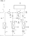
Fig. 3 is an overall configuration diagram of the heat pump according to the embodiment of the present invention and illustrates a case where a refrigerant circulates in a B mode. Further, a location through which the refrigerant does not flow is indicated by a broken line. -
Fig. 4 is an overall configuration diagram of the heat pump according to the embodiment of the present invention and illustrates a case where a refrigerant circulates in a C mode. Further, a location through which the refrigerant does not flow is indicated by a broken line. -
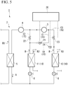
Fig. 5 is an overall configuration diagram of the heat pump according to the embodiment of the present invention and illustrates a case where a refrigerant circulates in a D mode. Further, a location through which the refrigerant does not flow is indicated by a broken line. - Hereinafter, a
heat pump 1 according to the embodiment of the present invention will be described. - As illustrated in
Fig. 1 , theheat pump 1 according to the present embodiment has arefrigerant circuit 2 which is operated in a two-stage compression cycle. Therefrigerant circuit 2 has a low-stage side compressor 3, a high-stage side compressor 4, acondenser 5, an expansion valve (expansion mechanism) 6, and anevaporator 10, and the components are connected by apipe 15 in this order. Then, for example, a refrigerant R such as carbon dioxide circulates through therefrigerant circuit 2. Here, the refrigerant R is not particularly limited to carbon dioxide. - The low-
stage side compressor 3 sucks the refrigerant R and compresses the refrigerant R. - The high-stage side compressor 4 is connected in series to the low-
stage side compressor 3, and compresses the refrigerant R discharged from the low-stage side compressor 3 to a higher pressure. - The
condenser 5 exchanges heat between the high-temperature and high-pressure refrigerant R discharged from the high-stage side compressor 4 and a heating medium R1 such as air or water to cool and condense the refrigerant R. - The
expansion valve 6 adiabatically expands the refrigerant R from thecondenser 5 and decompresses the refrigerant R. A plurality (two in this embodiment) ofexpansion valves 6 are provided on an upstream side (inlet side) of theevaporator 10 in correspondence with afirst evaporator 11 and asecond evaporator 12 described later. - In the present embodiment, the
first evaporator 11 and thesecond evaporator 12 are provided as theevaporator 10. Thefirst evaporator 11 and thesecond evaporator 12 are provided in parallel. - The
first evaporator 11 is an air heat exchanger which performs heat exchange between the refrigerant R which has passed through theexpansion valve 6 and air serving as the heating medium R2, for example. - The
pipe 15 between thefirst evaporator 11 and an upstream side (suction side) of the low-stage side compressor 3 forms a first flow path C1. The first flow path C1 includes afirst valve 21 which opens or closes the first flow path C1 so that the refrigerant R can flow through the first flow path C1 or cannot flow through the first flow path C1. - The
pipe 15 between thefirst evaporator 11 and an upstream side (a suction side of the high-stage side compressor 4 and a discharge side of the low-stage side compressor 3) of the high-stage side compressor 4 forms a second flow path C2. The second flow path C2 includes asecond valve 22 which opens or closes the second flow path C2 so that the refrigerant R can flow through the second flow path C2 or cannot flow through the second flow path C2. In the present embodiment, the first flow path C1 is provided so as to branch from the second flow path C2 on an upstream side of a position where thesecond valve 22 is provided, that is, on a side closer to thefirst evaporator 11. - The
second evaporator 12 is a water heat exchanger which performs heat exchange between the refrigerant R which has passed through theexpansion valve 6 and water serving as the heating medium R3, for example. - The
pipe 15 between thesecond evaporator 12 and the upstream side (suction side) of the low-stage side compressor 3 forms a third flow path C3. The third flow path C3 includes athird valve 23 which opens or closes the third flow path C3 so that the refrigerant R can flow through the third flow path C3 or cannot flow through the third flow path C3. In the present embodiment, the first flow path C1 is connected to the third flow path C3 on a downstream side of a position where thethird valve 23 is provided, that is, at a position closer to the low-stage side compressor 3. - The
pipe 15 between thesecond evaporator 12 and the upstream side (the suction side of the high-stage side compressor 4 and the discharge side of the low-stage side compressor 3) of the high-stage side compressor 4 forms a fourth flow path C4. The fourth flow path C4 includes afourth valve 24 which opens or closes the fourth flow path C4 so that the refrigerant R can flow through the fourth flow path C4 or cannot flow through the fourth flow path C4. In the present embodiment, the fourth flow path C4 is provided so as to branch from the third flow path C3 on an upstream side of a position where thethird valve 23 is provided, that is, on a side closer to thesecond evaporator 12. - Further, in this embodiment, a
control unit 30 such as a MICRO-PROCESSING UNIT (MPU) for opening or closing thefirst valve 21, thesecond valve 22, thethird valve 23, and thefourth valve 24 is provided. - The
control unit 30 opens or closes thefirst valve 21, thesecond valve 22, thethird valve 23, and thefourth valve 24 according to loads (heat exchange amounts) on thefirst evaporator 11 and thesecond evaporator 12. - Next, a control method of the opening or closing operation of each valve in the
control unit 30 will be described. - Hereinafter, a temperature of the refrigerant R flowing out from the
first evaporator 11 is defined as T1, and a temperature of the refrigerant R flowing out from thesecond evaporator 12 is defined as T2. - A case where T1 <T2 is satisfied is an A mode (first state). In this mode, as illustrated in
Fig. 2 , thecontrol unit 30 closes thesecond valve 22 and opens thefirst valve 21 so that the refrigerant R from thefirst evaporator 11 is introduced into the low-stage side compressor 3. Therefore, the refrigerant R from thefirst evaporator 11 is compressed by the low-stage side compressor 3, and thereafter, is compressed by the high-stage side compressor 4. - Further, in this mode, the
control unit 30 closes thethird valve 23 and opens thefourth valve 24 so that the refrigerant R from thesecond evaporator 12 is introduced only into the high-stage side compressor 4 without passing through the low-stage side compressor 3. Therefore, the refrigerant R from thesecond evaporator 12 is compressed only by the high-stage side compressor 4. - A case where T1> T2 is a B mode (second state). In the present mode, as illustrated in
Fig. 3 , thecontrol unit 30 closes thefirst valve 21 and open thesecond valve 22 so that the refrigerant R from thefirst evaporator 11 is introduced only into the high-stage side compressor 4 without passing through the low-stage side compressor 3. Therefore, the refrigerant R from thefirst evaporator 11 is compressed only by the high-stage side compressor 4 without passing through the low-stage side compressor 3. - In addition, in this mode, the
control unit 30 closes thefourth valve 24 and opens thethird valve 23 so that the refrigerant R from thesecond evaporator 12 is introduced into the low-stage side compressor 3. Therefore, the refrigerant R from thesecond evaporator 12 is compressed by the low-stage side compressor 3, and thereafter, is compressed by the high-stage side compressor 4. - A C mode is when T1 ≒ T2 is satisfied and the temperature of the refrigerant R flowing out from the
condenser 5 is equal to T1 and T2. In this mode, as illustrated inFig 4 , thecontrol unit 30 stops an operation of the low-stage side compressor 3. Further, thecontrol unit 30 closes thefirst valve 21 and thethird valve 23 and opens thesecond valve 22 and thefourth valve 24 so that the refrigerant R flowing out from thefirst evaporator 11 and thesecond evaporator 12 is introduced only into the high-stage side compressor 4 without passing through the low-stage side compressor 3. Therefore, both the refrigerant R from thefirst evaporator 11 and the refrigerant R from thesecond evaporator 12 are compressed by the high-stage side compressor 4 without passing through the low-stage side compressor 3. - A D mode is when T1 ≒ T2 is satisfied and a temperature difference between the temperature of the refrigerant R flowing out from the
condenser 5 and T1 and T2 is large. In this mode, as illustrated inFig. 5 , thecontrol unit 30 closes thesecond valve 22 and thefourth valve 24 and opens thefirst valve 21 and thethird valve 23 so that the refrigerant R flowing out from thefirst evaporator 11 and thesecond evaporator 12 is introduced into the low-stage side compressor 3. Therefore, both the refrigerant R from thefirst evaporator 11 and the refrigerant R from thesecond evaporator 12 are compressed by the low-stage side compressor 3, and thereafter, are compressed by the high-stage side compressor 4. - The
heat pump 1 according to the present embodiment described above includes thefirst evaporator 11 and thesecond evaporator 12. That is, theheat pump 1 has a multi-source typerefrigerant circuit 2 including a plurality of heat exchangers having different heat exchange amounts or installation environments, that is, thefirst evaporator 11 and thesecond evaporator 12. - Here, in each evaporator 10, the load (heat exchange amount) fluctuates and the temperature of the refrigerant R is changed. Accordingly, in some cases, the state of the refrigerant R directed toward the low-
stage side compressor 3 and the high-stage side compressor 4 may not be optimum for compression in the low-stage side compressor 3 and the high-stage side compressor 4. In the present embodiment, thecontrol unit 30 opens or closes the first flow path C1, the second flow path C2, the third flow path C3, and the fourth flow path C4 by thefirst valve 21, thesecond valve 22, thethird valve 23, and thefourth valve 24 so that not only can the refrigerant R be introduced from thefirst evaporator 11 into the low-stage side compressor 3, but also the refrigerant R can be directly introduced into the high-stage side compressor 4 by bypassing the low-stage side compressor 3. - Further, at the same time as switching of a circulation path of the refrigerant R from the
first evaporator 11, a circulation path of the refrigerant R from thesecond evaporator 12 can be switched. That is, not only can the refrigerant R be introduced from thesecond evaporator 12 into the low-stage side compressor 3, but also the refrigerant R can be directly introduced into the high-stage side compressor 4 by bypassing the low-stage side compressor 3. - Specifically, by operating the
first valve 21, thesecond valve 22, thethird valve 23, and thefourth valve 24 from the A mode to the D mode, according to the state of the refrigerant R flowing out from each evaporator 10 (11, 12), an introduction path of the refrigerant R can be switched to the compressor capable of performing optimum compression of the low-stage side compressor 3 and the high-stage side compressor 4. Therefore, the refrigerant R in a state optimum for compression can be introduced into the low-stage side compressor 3 and the high-stage side compressor 4, and an efficient operation can be performed. - Further, by providing the
control unit 30, the introduction path of the refrigerant R can be automatically switched to the compressor capable of performing optimum compression of the low-stage side compressor 3 and the high-stage side compressor 4 according to the state of the refrigerant R flowing out from each of thefirst evaporator 11 and thesecond evaporator 12. - Further, since the flow of the refrigerant R can be switched between the A mode and the B mode, the refrigerant R from the
first evaporator 11 can be introduced into any one of the low-stage side compressor 3 and the high-stage side compressor 4, and the refrigerant R from thesecond evaporator 12 can be introduced into any one of the low-stage side compressor 3 and the high-stage side compressor 4. - That is, the flow of the refrigerant R from the
first evaporator 11 and the flow of the refrigerant R from thesecond evaporator 12 do not interfere with each other, the refrigerant R circulates so that the flow of the refrigerant R from thefirst evaporator 11 and the flow of the refrigerant R from thesecond evaporator 12 cross each other, and can flow into the low-stage side compressor 3 and the high-stage side compressor 4. Therefore, a degree of freedom of an operation increases. - Hereinbefore, the embodiment of the present invention is described in detail with reference to the drawings. However, respective configurations in the embodiment and a combination thereof are merely examples, and addition, omission, substitution, and other modifications of configurations can be made within a scope which does not depart from the gist of the present invention. In addition, the present invention is not limited by the embodiment, but is limited only by claims.
- For example, the
control unit 30 does not necessarily have to be provided. In this case, thefirst valve 21, thesecond valve 22, thethird valve 23, and thefourth valve 24 may be manually opened or closed. - Further, three or
more evaporators 10 may be provided, and the number of theevaporators 10 is not limited to the above-described case. - According to the above-described heat pump, the refrigerant in the state optimum for compression can be introduced into the low-stage side compressor and the high-stage side compressor, and an efficient operation can be performed.
-
- 1 Heat pump
- 2 Refrigerant circuit
- 3 Low-stage side compressor
- 4 High-stage side compressor
- 5 Condenser
- 6 Expansion valve (expansion mechanism)
- 10 Evaporator
- 11 First evaporator
- 12 Second evaporator
- 15 Pipe
- 21 First valve
- 22 Second valve
- 23 Third valve
- 24 Fourth valve
- 30 Control unit
- R Refrigerant
- R1, R2, R3 Heating medium
- C1 First flow path
- C2 Second flow path
- C3 Third flow path
- C4 Fourth flow path
Claims (3)
- A heat pump comprising:a low-stage side compressor;a high-stage side compressor which is connected to a downstream side of the low-stage side compressor in series,a condenser which is connected to a downstream side of the high-stage side compressor;an expansion mechanism which is connected to a downstream side of the condenser;a first evaporator and a second evaporator which are connected to a downstream side of the expansion mechanism in parallel;a first flow path through which a downstream side of the first evaporator and an upstream side of the low-stage side compressor are connected to each other;a first valve which opens or closes the first flow path;a second flow path through which the downstream side of the first evaporator and an upstream side of the high-stage side compressor are connected to each other;a second valve which opens or closes the second flow path;a third flow path through which a downstream side of the second evaporator and the upstream side of the low-stage side compressor are connected to each other;a third valve which opens or closes the third flow path;a fourth flow path through which the downstream side of the second evaporator and the upstream side of the high-stage side compressor are connected to each other; anda fourth valve which opens or closes the fourth flow path.
- The heat pump according to claim 1, further comprising:
a control unit which controls opening or closing operations of the first valve, the second valve, the third valve, and the fourth valve based on loads on the first evaporator and the second evaporator. - The heat pump according to claim 2,
wherein the control unit controls the opening or closing operations of the first valve, the second valve, the third valve, and the fourth valve so that a first state where a refrigerant from the first evaporator is introduced into the low-stage side compressor and a refrigerant from the second evaporator is directly introduced into the high-stage side compressor and a second state where the refrigerant from the first evaporator is directly introduced into the high-stage side compressor and the refrigerant from the second evaporator is introduced into the low-stage side compressor are switchable to each other.
Applications Claiming Priority (2)
| Application Number | Priority Date | Filing Date | Title |
|---|---|---|---|
| JP2017215660A JP6373469B1 (en) | 2017-11-08 | 2017-11-08 | heat pump |
| PCT/JP2018/041487 WO2019093420A1 (en) | 2017-11-08 | 2018-11-08 | Heat pump |
Publications (2)
| Publication Number | Publication Date |
|---|---|
| EP3708924A1 true EP3708924A1 (en) | 2020-09-16 |
| EP3708924A4 EP3708924A4 (en) | 2021-08-04 |
Family
ID=63165908
Family Applications (1)
| Application Number | Title | Priority Date | Filing Date |
|---|---|---|---|
| EP18877202.4A Pending EP3708924A4 (en) | 2017-11-08 | 2018-11-08 | HEAT PUMP |
Country Status (4)
| Country | Link |
|---|---|
| EP (1) | EP3708924A4 (en) |
| JP (1) | JP6373469B1 (en) |
| CN (1) | CN111316047A (en) |
| WO (1) | WO2019093420A1 (en) |
Families Citing this family (3)
| Publication number | Priority date | Publication date | Assignee | Title |
|---|---|---|---|---|
| US11273687B2 (en) | 2020-04-30 | 2022-03-15 | Thermo King Corporation | System and method of energy efficient operation of a transport climate control system |
| CN115143658B (en) * | 2022-07-01 | 2024-09-17 | 浙江国祥股份有限公司 | Double-working-condition water chilling unit and control method thereof |
| JP2024079347A (en) * | 2022-11-30 | 2024-06-11 | 株式会社豊田自動織機 | Vehicle Thermal Management Systems |
Family Cites Families (12)
| Publication number | Priority date | Publication date | Assignee | Title |
|---|---|---|---|---|
| JPS56105259A (en) * | 1980-01-23 | 1981-08-21 | Hitachi Ltd | Multiple temperature refrigerator |
| JPH0210063A (en) * | 1988-06-29 | 1990-01-12 | Toshiba Corp | Device for refrigerating cycle |
| JPH0611198A (en) * | 1991-02-08 | 1994-01-21 | Mitsubishi Electric Corp | Refrigeration equipment |
| JP3036310B2 (en) * | 1992-08-01 | 2000-04-24 | 三菱電機株式会社 | Multi-temperature generation circuit by vapor compression refrigeration cycle |
| JPH09145189A (en) * | 1995-11-27 | 1997-06-06 | Sanyo Electric Co Ltd | Refrigerating cycle and air conditioner provided with the refrigerating cycle |
| US7353660B2 (en) * | 2004-09-13 | 2008-04-08 | Carrier Corporation | Multi-temperature cooling system with unloading |
| JP4169080B2 (en) * | 2007-03-29 | 2008-10-22 | 三菱電機株式会社 | Freezer refrigerator |
| JP2009079863A (en) * | 2007-09-27 | 2009-04-16 | Mitsubishi Heavy Ind Ltd | Refrigeration device |
| JP2009210138A (en) * | 2008-02-29 | 2009-09-17 | Mitsubishi Heavy Ind Ltd | Refrigerating cycle system |
| JP5375919B2 (en) * | 2011-09-30 | 2013-12-25 | ダイキン工業株式会社 | heat pump |
| JP6548890B2 (en) | 2014-10-31 | 2019-07-24 | 三菱重工サーマルシステムズ株式会社 | Control device of refrigeration cycle, refrigeration cycle, and control method of refrigeration cycle |
| JP2017215660A (en) | 2016-05-30 | 2017-12-07 | キヤノン株式会社 | Image processing apparatus, image processing method, and program |
-
2017
- 2017-11-08 JP JP2017215660A patent/JP6373469B1/en active Active
-
2018
- 2018-11-08 CN CN201880072403.3A patent/CN111316047A/en active Pending
- 2018-11-08 EP EP18877202.4A patent/EP3708924A4/en active Pending
- 2018-11-08 WO PCT/JP2018/041487 patent/WO2019093420A1/en not_active Ceased
Also Published As
| Publication number | Publication date |
|---|---|
| JP6373469B1 (en) | 2018-08-15 |
| CN111316047A (en) | 2020-06-19 |
| EP3708924A4 (en) | 2021-08-04 |
| WO2019093420A1 (en) | 2019-05-16 |
| JP2019086238A (en) | 2019-06-06 |
Similar Documents
| Publication | Publication Date | Title |
|---|---|---|
| JP5332604B2 (en) | Cooling and heating simultaneous operation type air conditioner | |
| US7331196B2 (en) | Refrigerating apparatus and refrigerator | |
| EP2860471B1 (en) | Multi-room air conditioner | |
| EP3534082B1 (en) | Air conditioner | |
| EP3521721B1 (en) | Air conditioner | |
| US20060218952A1 (en) | Refrigerating device and refrigerator | |
| US20150300666A1 (en) | Air conditioner and air conditioner construction method | |
| EP3792570A1 (en) | Refrigeration cycle system | |
| CN111316047A (en) | heat pump | |
| US12442549B2 (en) | Air conditioner | |
| US11994306B2 (en) | Outdoor unit and air-conditioning apparatus | |
| EP3587957B1 (en) | Heat pump and method of controlling heat pump | |
| KR102903310B1 (en) | Air conditioning apparatus | |
| EP3862656B1 (en) | Refrigeration cycle device | |
| EP3705809A1 (en) | Heat pump | |
| EP4033175B1 (en) | Air conditioner | |
| WO2018074370A1 (en) | Refrigeration system and indoor unit | |
| CN110234938B (en) | Outdoor system of air conditioner | |
| EP4563915A1 (en) | Air conditioner | |
| JP2017062083A (en) | Air conditioner | |
| CN119866421A (en) | Refrigeration cycle device | |
| US20170089621A1 (en) | Air conditioner system | |
| JP2016166703A (en) | Air conditioner |
Legal Events
| Date | Code | Title | Description |
|---|---|---|---|
| STAA | Information on the status of an ep patent application or granted ep patent |
Free format text: STATUS: THE INTERNATIONAL PUBLICATION HAS BEEN MADE |
|
| PUAI | Public reference made under article 153(3) epc to a published international application that has entered the european phase |
Free format text: ORIGINAL CODE: 0009012 |
|
| STAA | Information on the status of an ep patent application or granted ep patent |
Free format text: STATUS: REQUEST FOR EXAMINATION WAS MADE |
|
| 17P | Request for examination filed |
Effective date: 20200602 |
|
| AK | Designated contracting states |
Kind code of ref document: A1 Designated state(s): AL AT BE BG CH CY CZ DE DK EE ES FI FR GB GR HR HU IE IS IT LI LT LU LV MC MK MT NL NO PL PT RO RS SE SI SK SM TR |
|
| AX | Request for extension of the european patent |
Extension state: BA ME |
|
| DAV | Request for validation of the european patent (deleted) | ||
| DAX | Request for extension of the european patent (deleted) | ||
| A4 | Supplementary search report drawn up and despatched |
Effective date: 20210706 |
|
| RIC1 | Information provided on ipc code assigned before grant |
Ipc: F25B 1/10 20060101AFI20210630BHEP Ipc: F25B 5/02 20060101ALI20210630BHEP Ipc: F25B 41/22 20210101ALI20210630BHEP |
|
| RAP3 | Party data changed (applicant data changed or rights of an application transferred) |
Owner name: THE KANSAI ELECTRIC POWER CO., INC. Owner name: CHUBU ELECTRIC POWER CO., INC. Owner name: MITSUBISHI HEAVY INDUSTRIES THERMAL SYSTEMS, LTD. |
|
| RAP1 | Party data changed (applicant data changed or rights of an application transferred) |
Owner name: CHUBU ELECTRIC POWER CO., INC. Owner name: MITSUBISHI HEAVY INDUSTRIES THERMAL SYSTEMS, LTD. |
|
| STAA | Information on the status of an ep patent application or granted ep patent |
Free format text: STATUS: EXAMINATION IS IN PROGRESS |
|
| 17Q | First examination report despatched |
Effective date: 20250526 |