EP3708844A1 - Turbocharger and bearing housing therefor - Google Patents
Turbocharger and bearing housing therefor Download PDFInfo
- Publication number
- EP3708844A1 EP3708844A1 EP19161807.3A EP19161807A EP3708844A1 EP 3708844 A1 EP3708844 A1 EP 3708844A1 EP 19161807 A EP19161807 A EP 19161807A EP 3708844 A1 EP3708844 A1 EP 3708844A1
- Authority
- EP
- European Patent Office
- Prior art keywords
- bearing housing
- arm
- backplate
- bearing
- housing body
- Prior art date
- Legal status (The legal status is an assumption and is not a legal conclusion. Google has not performed a legal analysis and makes no representation as to the accuracy of the status listed.)
- Granted
Links
Images


Classifications
-
- F—MECHANICAL ENGINEERING; LIGHTING; HEATING; WEAPONS; BLASTING
- F01—MACHINES OR ENGINES IN GENERAL; ENGINE PLANTS IN GENERAL; STEAM ENGINES
- F01D—NON-POSITIVE DISPLACEMENT MACHINES OR ENGINES, e.g. STEAM TURBINES
- F01D25/00—Component parts, details, or accessories, not provided for in, or of interest apart from, other groups
- F01D25/24—Casings; Casing parts, e.g. diaphragms, casing fastenings
- F01D25/243—Flange connections; Bolting arrangements
-
- F—MECHANICAL ENGINEERING; LIGHTING; HEATING; WEAPONS; BLASTING
- F04—POSITIVE - DISPLACEMENT MACHINES FOR LIQUIDS; PUMPS FOR LIQUIDS OR ELASTIC FLUIDS
- F04D—NON-POSITIVE-DISPLACEMENT PUMPS
- F04D29/00—Details, component parts, or accessories
- F04D29/04—Shafts or bearings, or assemblies thereof
- F04D29/046—Bearings
-
- F—MECHANICAL ENGINEERING; LIGHTING; HEATING; WEAPONS; BLASTING
- F04—POSITIVE - DISPLACEMENT MACHINES FOR LIQUIDS; PUMPS FOR LIQUIDS OR ELASTIC FLUIDS
- F04D—NON-POSITIVE-DISPLACEMENT PUMPS
- F04D17/00—Radial-flow pumps, e.g. centrifugal pumps; Helico-centrifugal pumps
- F04D17/08—Centrifugal pumps
- F04D17/10—Centrifugal pumps for compressing or evacuating
-
- F—MECHANICAL ENGINEERING; LIGHTING; HEATING; WEAPONS; BLASTING
- F04—POSITIVE - DISPLACEMENT MACHINES FOR LIQUIDS; PUMPS FOR LIQUIDS OR ELASTIC FLUIDS
- F04D—NON-POSITIVE-DISPLACEMENT PUMPS
- F04D25/00—Pumping installations or systems
- F04D25/02—Units comprising pumps and their driving means
- F04D25/04—Units comprising pumps and their driving means the pump being fluid-driven
-
- F—MECHANICAL ENGINEERING; LIGHTING; HEATING; WEAPONS; BLASTING
- F04—POSITIVE - DISPLACEMENT MACHINES FOR LIQUIDS; PUMPS FOR LIQUIDS OR ELASTIC FLUIDS
- F04D—NON-POSITIVE-DISPLACEMENT PUMPS
- F04D29/00—Details, component parts, or accessories
- F04D29/05—Shafts or bearings, or assemblies thereof, specially adapted for elastic fluid pumps
- F04D29/056—Bearings
- F04D29/0563—Bearings cartridges
-
- F—MECHANICAL ENGINEERING; LIGHTING; HEATING; WEAPONS; BLASTING
- F04—POSITIVE - DISPLACEMENT MACHINES FOR LIQUIDS; PUMPS FOR LIQUIDS OR ELASTIC FLUIDS
- F04D—NON-POSITIVE-DISPLACEMENT PUMPS
- F04D29/00—Details, component parts, or accessories
- F04D29/40—Casings; Connections of working fluid
- F04D29/42—Casings; Connections of working fluid for radial or helico-centrifugal pumps
- F04D29/4206—Casings; Connections of working fluid for radial or helico-centrifugal pumps especially adapted for elastic fluid pumps
-
- F—MECHANICAL ENGINEERING; LIGHTING; HEATING; WEAPONS; BLASTING
- F04—POSITIVE - DISPLACEMENT MACHINES FOR LIQUIDS; PUMPS FOR LIQUIDS OR ELASTIC FLUIDS
- F04D—NON-POSITIVE-DISPLACEMENT PUMPS
- F04D29/00—Details, component parts, or accessories
- F04D29/60—Mounting; Assembling; Disassembling
- F04D29/62—Mounting; Assembling; Disassembling of radial or helico-centrifugal pumps
- F04D29/624—Mounting; Assembling; Disassembling of radial or helico-centrifugal pumps especially adapted for elastic fluid pumps
-
- F—MECHANICAL ENGINEERING; LIGHTING; HEATING; WEAPONS; BLASTING
- F16—ENGINEERING ELEMENTS AND UNITS; GENERAL MEASURES FOR PRODUCING AND MAINTAINING EFFECTIVE FUNCTIONING OF MACHINES OR INSTALLATIONS; THERMAL INSULATION IN GENERAL
- F16C—SHAFTS; FLEXIBLE SHAFTS; ELEMENTS OR CRANKSHAFT MECHANISMS; ROTARY BODIES OTHER THAN GEARING ELEMENTS; BEARINGS
- F16C17/00—Sliding-contact bearings for exclusively rotary movement
- F16C17/04—Sliding-contact bearings for exclusively rotary movement for axial load only
-
- F—MECHANICAL ENGINEERING; LIGHTING; HEATING; WEAPONS; BLASTING
- F02—COMBUSTION ENGINES; HOT-GAS OR COMBUSTION-PRODUCT ENGINE PLANTS
- F02C—GAS-TURBINE PLANTS; AIR INTAKES FOR JET-PROPULSION PLANTS; CONTROLLING FUEL SUPPLY IN AIR-BREATHING JET-PROPULSION PLANTS
- F02C6/00—Plural gas-turbine plants; Combinations of gas-turbine plants with other apparatus; Adaptations of gas-turbine plants for special use
- F02C6/04—Gas-turbine plants providing heated or pressurised working fluid for other apparatus, e.g. without mechanical power output
- F02C6/10—Gas-turbine plants providing heated or pressurised working fluid for other apparatus, e.g. without mechanical power output supplying working fluid to a user, e.g. a chemical process, which returns working fluid to a turbine of the plant
- F02C6/12—Turbochargers, i.e. plants for augmenting mechanical power output of internal-combustion piston engines by increase of charge pressure
-
- F—MECHANICAL ENGINEERING; LIGHTING; HEATING; WEAPONS; BLASTING
- F05—INDEXING SCHEMES RELATING TO ENGINES OR PUMPS IN VARIOUS SUBCLASSES OF CLASSES F01-F04
- F05D—INDEXING SCHEME FOR ASPECTS RELATING TO NON-POSITIVE-DISPLACEMENT MACHINES OR ENGINES, GAS-TURBINES OR JET-PROPULSION PLANTS
- F05D2220/00—Application
- F05D2220/40—Application in turbochargers
-
- F—MECHANICAL ENGINEERING; LIGHTING; HEATING; WEAPONS; BLASTING
- F16—ENGINEERING ELEMENTS AND UNITS; GENERAL MEASURES FOR PRODUCING AND MAINTAINING EFFECTIVE FUNCTIONING OF MACHINES OR INSTALLATIONS; THERMAL INSULATION IN GENERAL
- F16C—SHAFTS; FLEXIBLE SHAFTS; ELEMENTS OR CRANKSHAFT MECHANISMS; ROTARY BODIES OTHER THAN GEARING ELEMENTS; BEARINGS
- F16C2360/00—Engines or pumps
- F16C2360/23—Gas turbine engines
- F16C2360/24—Turbochargers
Definitions
- the present disclosure relates to a turbocharger for an internal combustion engine. More particularly, the present disclosure relates to a bearing housing for a turbocharger and to a turbocharger comprising this bearing housing.
- Turbochargers deliver compressed air to an intake of an internal combustion engine, allowing more fuel to be combusted. As a result, a power density of the engine is increased without significantly increasing engine weight. Turbochargers thus permit the use of smaller engines that develop the same amount of power as larger, normally aspirated engines. Using a smaller engine in a vehicle has the desired effect of decreasing the vehicle mass, increasing performance and reducing fuel consumption. Moreover, the use of turbochargers leads to an improved combustion and, therefore, to reduced emissions.
- Turbochargers include a turbine housing having an inlet passage connected to an exhaust manifold of the engine, a compressor housing having an outlet passage connected to an intake manifold of the engine, and a bearing housing interconnecting the turbine housing and the compressor housing.
- An exhaust gas flow from the exhaust manifold rotatably drives a turbine wheel in the turbine housing.
- the turbine wheel is connected via a rotor shaft rotatably supported in the bearing housing to a compressor wheel in the compressor housing. Rotation of the turbine wheel by the exhaust gas flow thus causes rotation of the compressor wheel.
- the rotating compressor wheel draws in ambient air via a so-called inducer of the compressor housing and compresses the air. Downstream of the compressor wheel the compressed air enters a diffusor channel from which the compressed air is guided via a compressor cover to the intake manifold.
- the outlet passage also referred to as exducer.
- the outlet passage often has a conical shape and opens out into a flange for connecting the turbocharger to a catalytic converter assembly.
- US 2018/0328371 A1 discloses a turbocharger of the type discussed above with a compressor housing in which a diffusor channel is defined between a body of the compressor housing and a backplate.
- the backplate has a first face that delimits the diffusor channel and a second face opposite the first face that is supported against a face of the bearing housing.
- the backplate is constructed and arranged to attach to the compressor housing and the bearing housing.
- Turbochargers tend to significantly heat up during operation. It is therefore generally desirable to limit a heat flow between the different components of a turbocharger while at the same time permitting efficient heat convection to ambient atmosphere.
- turbocharger with improved thermal properties.
- bearing housing for such a turbocharger.
- a bearing housing for a turbocharger comprising a bearing housing body configured to receive a rotor shaft along a longitudinal axis of the bearing housing body.
- the bearing housing further comprises a hub connected to the bearing housing body and defining an opening into the bearing housing body, wherein the opening is configured to receive a rotor shaft bearing.
- the bearing housing comprises at least one arm extending radially from the hub, the at least one arm having a first end connected to the hub and a second end opposite to the first end, wherein the second end of the at least one arm comprises a connection structure configured to connect the bearing housing with a compressor housing of the turbocharger.
- the at least one arm has a length extending from its first end to its second end, and a width extending perpendicular to its length.
- the width may be defined to substantially lie in a plane that extends perpendicular to the longitudinal axis.
- the length of the at least one arm is larger than the width of that arm in a central region along its length.
- the central region may lie in the middle between the first end and the second end of the at least one arm.
- the bearing housing may comprise two or more arms spaced apart in a circumferential direction of the longitudinal axis. In case multiple arms are provided, two or more or all of these arms may have substantially the same geometric configuration.
- the bearing housing comprises exactly three arms. In other variants, the bearing housing comprises exactly two, four or five arms. Adjacent ones of the two or more arms may be spaced apart in a circumferential direction of the longitudinal axis at substantially the same angular distance. For example, in a variant with two arms the angular distance may be approximately 180°, in a variant with three arms the angular distance may be approximately 120°, and so on.
- connection surface facing away from the bearing housing body.
- the connection surface may be smaller than the complete surface of the arm between the first end and the second end that is directed towards the compressor housing.
- the connection surface may be less than 50% or less than 25% of the complete arm surface.
- the at least one arm may comprise a recessed surface between the first end and the second end.
- the recessed surface may face away from the bearing housing body.
- the recessed surface may be offset, or recessed, relative to the connection surface towards the bearing housing body.
- connection surface may lie in a first plane perpendicularly intersecting the longitudinal axis.
- the recessed surface may lie in a second plane that is generally parallel to the first plane.
- the second plane is offset, or recessed, relative to the first plane towards the bearing housing body so as to define a space between the first plane and the second plane.
- the space may be configured to accommodate at least a portion of a compressor housing backplate in the assembled state of the turbocharger.
- the hub may comprise a protrusion that extends around the opening into the bearing housing body and protrudes over an adjacent surface (e.g., the recessed surface) of the at least one arm facing away from the bearing housing body.
- the protrusion extends into the space between the first plane and the second plane.
- connection structure may take various forms.
- the connection structure comprises at least one through-opening.
- Each through-opening may be configured to receive a bolt member to connect the bearing housing with a compressor housing of the turbocharger.
- a housing assembly comprising the bearing housing as presented herein and a compressor housing connected to the at least one arm of the bearing housing.
- the compressor housing comprises a compressor housing body configured to receive a compressor wheel supported on the rotor shaft, and a backplate closing the compressor housing body towards the bearing housing.
- the backplate may be clamped between the compressor housing body and the bearing housing.
- the backplate may not be attached to the compressor housing body by a separate attachment member such as a screw.
- the backplate may not be attached to the bearing housing by a separate attachment member such as a screw.
- the at least one arm may be spaced apart from the backplate. In this manner, the backplate may be thermally decoupled from the at least one arm and, optionally, other components of the bearing housing.
- the backplate may have a circumference in a plane extending perpendicular to the longitudinal axis.
- the first end of the at least one arm may lie radially inside the circumference.
- the second end of the at least one arm may lie radially outside the circumference.
- the backplate may have a face directed towards the bearing housing body.
- an open space may be defined between two adjacent arms, the face of the backplate and the bearing housing body.
- the open space may be configured to enable heat convection to ambient atmosphere.
- the at least one arm may have a face directed towards the backplate, wherein an air gap configured to enable heat convection to ambient atmosphere is provided between the face of the backplate and the face of the at least one arm.
- the backplate may comprise an annular recess having a depth extending towards the compressor housing body and an open side facing the bearing housing.
- the annular recess may assist heat convection.
- the backplate may at least partially extend into the opening of the bearing housing body.
- an axial support for the backplate may be located in the opening of the bearing housing body.
- the axial support may be defined by a step in the opening.
- a axial rotor shaft bearing, such as a thrust bearing, may functionally be arranged in a force transmitting manner between the backplate and the step.
- a fluid sealing may be arranged between the backplate and an inner wall of the opening of the bearing housing body.
- the fluid sealing may be configured to prevent a lubricating fluid accommodated in the opening from leaking out of the opening.
- At least one rotor shaft bearing may be accommodated in the opening of the bearing housing body.
- the at least one rotor shaft bearing may be an axial bearing such as a thrust bearing.
- the backplate In an axial force transmission path from the compressor body to the bearing housing, the backplate may be located downstream of the compressor housing body and upstream of the rotor shaft bearing, and the rotor shaft bearing may be located downstream of the backplate and upstream of the bearing housing.
- the backplate may be in direct contact with at least one of the compressor housing body and the rotor shaft bearing.
- one or more force transmission members may be arranged between any of these components.
- turbocharger comprising the housing assembly presented herein.
- the turbocharger may in particular comprise the compressor housing and the bearing housing.
- the turbocharger may additionally comprise a turbine housing.
- the bearing housing may interconnect the compressor housing and the turbine housing.
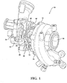
- Figs. 1 and 2 illustrate an embodiment of a turbocharger 10 for an internal combustion engine.
- the turbocharger 10 includes a housing assembly 12 consisting of a compressor housing 14, a bearing housing 16, and a turbine housing 18 that are connected to each other.
- the bearing housing 16 supports a rotor shaft 20 that defines an axis of rotation R1.
- a compressor wheel 22 with a plurality of blades is mounted on one end of the shaft 20 and is housed within the compressor housing 14.
- the turbine housing 18 has a turbine housing body 24 and houses a turbine wheel 26 with a plurality of blades.
- the turbine wheel 26 is mounted on an opposite end of the shaft 20 in relation to the compressor wheel 22.
- the turbine housing 18 includes an inlet passage 28 that is coupled to an exhaust manifold (not shown) of the engine to receive an exhaust gas flow.
- the inlet passage 28 has the form of a volute and directs the exhaust gas flow into the turbine housing body 24 towards the turbine wheel 26.
- the exhaust gas flow rotatably drives the turbine wheel 26 on the shaft 20, thereby causing the compressor wheel 22 to rotate also.
- the exhaust gas flow is discharged through a conically shaped outlet passage 32 of the turbine housing 18. This outlet passage 32 is also known as exducer.
- the guide apparatus is positioned within the turbine housing 18 and includes a plurality of guide vanes 34 located downstream of the inlet passage 26 and upstream of the turbine wheel 24.
- the space between adjacent guide vanes 34 defines a flow channel through which the exhaust gas flows to the turbine wheel 24.
- a respective cross-section of the flow channels is adjustable, as is known in the art, to realize a Variable Turbine Geometry (VTG).
- the compressor housing 14 includes an inlet passage 40. This inlet passage 40 is also referred to as inducer. Upon rotation of the compressor wheel 22, ambient air is drawn into the compressor housing 14 through the inlet passage 40 and compressed by the compressor wheel 22. Downstream of the compressor wheel 22 the compressed air enters a diffusor channel 42 from which the compressed air is guided via an outlet passage 44 in the form of a volute to an intake manifold (not shown) of the engine.
- the diffusor channel 42 is defined between a compressor housing body 46 and a backplate 48 of the compressor housing 14.
- a sealing ring 50 is arranged between a face of the backplate 48 directed towards the compressor housing body 46 and a face of the compressor housing body 46 directed towards the backplate 48. The sealing ring 50 prevents compressed air from leaking out of the compressor housing 14.
- the backplate 48 is substantially disk-shaped and has a diameter that is substantially larger than a diameter of the compressor wheel 22 so as to delimit the diffusor channel 42 that extends in a radial direction away from the compressor wheel 22.
- the backplate 48 has an annular recess 52 in a region where it delimits the diffusor channel 42.
- the backplate 48 has a cylindrical protrusion 54 on its face directed away from the compressor wheel 22.
- the backplate 48 comprises a central through-opening 56.
- the rotor shaft 20 extends through this through opening 56.
- a sleeve 58 also called flinger sleeve, is seated on the rotor shaft 20 so as to rotate together with the rotor shaft 20.
- the sleeve 58 has circumferential grooves facing towards the backplate 48 and each accommodating a piston ring (not shown in Fig. 2 ).
- the sleeve 58 and piston rings create a labyrinth sealing that prevents air leakage from the compressor housing 14 towards the bearing housing 16 and leakage of a lubricating fluid in the opposite direction.
- a similar labyrinth sealing is provided at the opposite end of the rotor shaft 20 adjacent the turbine wheel 26.
- the bearing housing 16 has a bearing housing body 62.
- the backplate 48 In an axial force transmission path from the compressor housing body 46 to the bearing housing body 62, the backplate 48 is located downstream of the compressor housing body 46 and upstream of an axial rotor shaft bearing 60 (also called thrust bearing).
- the axial bearing 60 is located downstream of the backplate 48 and upstream of the bearing housing body 62.
- An axial force acting on the backplate 48 in a direction towards the turbine housing 18 will be transferred from the backplate 48 via a face of its cylindrical protrusion 54 to the axial bearing 60 and from the axial bearing 60 to the compressor housing body 62.
- An axial force acting on the axial bearing 60 in the opposite direction will be transferred via the backplate 48 to the compressor housing body 48.
- such an axial force towards the compressor housing 14 can be transferred onto the axial bearing 60 by the rotor shaft 20 that has a stepped profile for cooperating with the axial bearing 60.
- the bearing housing body 62 and is configured to receive the rotor shaft 20 along a longitudinal axis L1 of the bearing housing body 62.
- the axis of rotation R1 of the rotor shaft therefore extends coaxial to the longitudinal axis L1 of the bearing housing body 62.
- the bearing housing 16 defines a surface 64 directed towards the compressor housing 14. The surface 64 lies in a plane that extends perpendicular to the longitudinal axis L1 of the bearing housing body 62.
- a hub 66 defines a generally cylindrical opening 68 into the bearing housing body 62.
- the hub 66 is integrally connected to the bearing housing body 62 and has a ring-shaped protrusion 70 over the surface 64.
- the opening 68 has a circular cross-section.
- the longitudinal axis L1 of the bearing housing body 62 extends through the center of the opening 68 (and through the center of the hub 66).
- the opening 68 has a step-wise decreasing diameter and is configured to receive multiple rotor shaft bearings.
- the axial bearing 60 is accommodated (see Fig. 2 ).
- the axial bearing 60 is supported against a step that defines a transition from the wider-diameter portion of the opening 68 to a smaller-diameter portion.
- the smaller-diameter portion of the opening 68 accommodates a journal bearing 76 for the rotor shaft 20 (see Fig. 2 ).
- the journal bearing 76 comprises two separate bearing components that are spaced apart from each other along the longitudinal axis L1 of the bearing housing body 62.
- the bearing housing body 62 has a system of fluid channels 78 to feed a lubricating fluid such as oil to the rotor shaft bearings 60, 76 (see Fig. 2 ).
- the cylindrical protrusion 54 of the backplate 48 partially extends into the opening 68 of the bearing housing body 62 to rest on the axial bearing 60.
- the ring-shaped protrusion 70 has a centering function when inserting the backplate protrusion 54 into the opening 68.
- a sealing ring 72 is arranged between an outer circumference of the cylindrical protrusion 54 and an inner wall of the opening 68. The sealing ring 72 prevents lubricating fluid from leaking out of the opening 68.
- the bearing housing 16 comprises at least one arm 80 for connecting the bearing housing 16 with the compressor housing 14. In the connected state, the backplate 48 is clamped between the bearing housing 16 and the compressor housing body 46 without any separate attachment of the backplate 48 to either one of the bearing housing 16 and the compressor housing 14.
- connection arms 80 extend radially from the hub 66. It will, however, be appreciated that more or less connection arms 80 may be provided in other embodiments.
- the two lower arms 80 in Fig. 3 may be integrated into a single connection structure having, for example, a semicircular shape. In such a configuration, only a single connection arm 80 will be provided, namely the upper arm 80 in Fig. 3 .
- connection arm 80 has a first end 82 connected to the hub 66 and a second end 84 opposite the first end 82.
- the second end 84 of each arm 80 comprises a connection structure 86 configured to connect the bearing housing 16 with the compressor housing 14.
- connection structure 86 takes the form of a through-opening configured to receive a bolt member 88 to connect the bearing housing 16 with the compressor housing 14 (see also Figs. 1 and 2 ).
- Each arm 80 has a length extending from its first end 82 to its second end 84. Moreover, each arm 80 has a width extending perpendicular to its length and substantially parallel to the surface 64. It is to be noted that the different arms 80 may have different lengths and different widths, as shown in Fig. 3 . In the embodiment illustrated in the drawings, the length of each arm 80 is substantially larger than the width of that arm 80 in the center between its first and the second ends 82, 84. Generally, the width of an arm 80 may be at least 1.4 times greater than the width of that arm 80 (e.g., at least 1.7 or 2.0 or 2.5 times larger).
- the three arms 80 are spaced apart from each other in a circumferential direction of the longitudinal axis L1 of the bearing housing body 62. As illustrated in Fig. 3 , an angular distance between each pair of adjacent arms 80 relative to the longitudinal axis L1 may approximately be the same for all arm pairs (e.g., lie between 110° and 140° in an exemplary three-arm configuration).
- each arm 80 comprises a connection surface 90 facing away from the bearing housing body 62 towards the compressor housing 14.
- the connection surfaces 90 of all arms 80 lie in a plane that perpendicularly intersects the longitudinal axis L1 of the bearing housing body 62.
- the area of the connection surface 90 of each arm 90 is smaller than the complete surface area of that arm 80 between its first and second ends 82, 84 and directed towards the compressor housing 14.
- the connection surface area of each arm 80 is less than 50% of the respective complete arm surface area towards the compressor housing 14. Such a reduction of the contact area towards the compressor housing 14 reduces heat transfer between the bearing housing 16 and the compressor housing 14.
- each of the arms 80 comprises a region between its first and second ends 82, 84 that is offset, or recessed, towards the bearing housing body 62 relative to its connection surface 90.
- the recessed regions of the three arms 80 define the surface 64.
- the recessed surface 64 lies in a plane that is generally parallel to the plane spanned by the connection surfaces 90 and is offset towards the bearing housing body 62 so as to define a space 94 between the two planes (see Fig. 2 ).
- the resulting space 94 is configured to accommodate a portion of the compressor housing backplate 48 without mechanical contact between the backplate 48 and the recessed surface 64. In this way, thermal decoupling of the backplate 48 from the bearing housing body 62 is improved.
- the backplate 48 has a circumference in a plane extending perpendicular to the longitudinal axis L1.
- the first end 82 (not shown in Fig. 4 ) of each arm 80 lies radially inside and the second end 84 of each arm 80 lies radially outside of that circumference.
- the arms 80 will thus reach over the backplate 48 without any mechanical contact therebetween.
- an air gap for heat convection to ambient atmosphere is provided between a face of the backplate 48 directed towards the arms 80 and a face of each of the arms 80 directed towards the backplate 48.
- open spaces are also defined between each pair of adjacent arms 80 in a circumferential direction relative to the longitudinal axis L1, as best seen in Fig. 3 .
- the backplate 48 may be made from a material that has a high thermal conductivity, such as aluminum.
- the provision of one or more arms 80 for connecting the bearing housing 16 to the compressor housing 14 results in a better thermal decoupling of the two housings 14, 16.
- thermal decoupling of the compressor housing backplate 48 from the bearing housing 16 can be improved.
- heat convection to ambient atmosphere can be facilitated by providing an air gap between the backplate 48 and the bearing housing 16. In this way, compressor efficiency is improved as the heat flow from the bearing housing 16 to the compressor housing 14 is reduced.
- connection arms 80 reduces the weight of the turbocharger 10 as a whole compared to connection solutions in which circumferentially continuous connection flanges are used. Moreover, a highly reliable bolted connection between the bearing housing 16 and the compressor housing 14 can be implemented in some variants. Such a bolted connection permits to reliably clamp the backplate 48 between the compressor housing body 46 and the bearing housing 16, without the need of a separate attachment of the backplate to any of the compressor housing body 46 and the bearing housing 16.
Landscapes
- Engineering & Computer Science (AREA)
- General Engineering & Computer Science (AREA)
- Mechanical Engineering (AREA)
- Supercharger (AREA)
Abstract
Description
- The present disclosure relates to a turbocharger for an internal combustion engine. More particularly, the present disclosure relates to a bearing housing for a turbocharger and to a turbocharger comprising this bearing housing.
- Turbochargers deliver compressed air to an intake of an internal combustion engine, allowing more fuel to be combusted. As a result, a power density of the engine is increased without significantly increasing engine weight. Turbochargers thus permit the use of smaller engines that develop the same amount of power as larger, normally aspirated engines. Using a smaller engine in a vehicle has the desired effect of decreasing the vehicle mass, increasing performance and reducing fuel consumption. Moreover, the use of turbochargers leads to an improved combustion and, therefore, to reduced emissions.
- Turbochargers include a turbine housing having an inlet passage connected to an exhaust manifold of the engine, a compressor housing having an outlet passage connected to an intake manifold of the engine, and a bearing housing interconnecting the turbine housing and the compressor housing. An exhaust gas flow from the exhaust manifold rotatably drives a turbine wheel in the turbine housing. The turbine wheel is connected via a rotor shaft rotatably supported in the bearing housing to a compressor wheel in the compressor housing. Rotation of the turbine wheel by the exhaust gas flow thus causes rotation of the compressor wheel. The rotating compressor wheel draws in ambient air via a so-called inducer of the compressor housing and compresses the air. Downstream of the compressor wheel the compressed air enters a diffusor channel from which the compressed air is guided via a compressor cover to the intake manifold.
- After having driven the turbine wheel, the exhaust gas flow is discharged from the turbine housing via an outlet passage, also referred to as exducer. The outlet passage often has a conical shape and opens out into a flange for connecting the turbocharger to a catalytic converter assembly.
-
US 2018/0328371 A1 discloses a turbocharger of the type discussed above with a compressor housing in which a diffusor channel is defined between a body of the compressor housing and a backplate. The backplate has a first face that delimits the diffusor channel and a second face opposite the first face that is supported against a face of the bearing housing. The backplate is constructed and arranged to attach to the compressor housing and the bearing housing. - Turbochargers tend to significantly heat up during operation. It is therefore generally desirable to limit a heat flow between the different components of a turbocharger while at the same time permitting efficient heat convection to ambient atmosphere.
- There is a need for a turbocharger with improved thermal properties. There also is a need for a bearing housing for such a turbocharger.
- According to one aspect of the present disclosure, a bearing housing for a turbocharger is provided, wherein the bearing housing comprises a bearing housing body configured to receive a rotor shaft along a longitudinal axis of the bearing housing body. The bearing housing further comprises a hub connected to the bearing housing body and defining an opening into the bearing housing body, wherein the opening is configured to receive a rotor shaft bearing. Moreover, the bearing housing comprises at least one arm extending radially from the hub, the at least one arm having a first end connected to the hub and a second end opposite to the first end, wherein the second end of the at least one arm comprises a connection structure configured to connect the bearing housing with a compressor housing of the turbocharger.
- The at least one arm has a length extending from its first end to its second end, and a width extending perpendicular to its length. The width may be defined to substantially lie in a plane that extends perpendicular to the longitudinal axis. In some variants, the length of the at least one arm is larger than the width of that arm in a central region along its length. The central region may lie in the middle between the first end and the second end of the at least one arm.
- The bearing housing may comprise two or more arms spaced apart in a circumferential direction of the longitudinal axis. In case multiple arms are provided, two or more or all of these arms may have substantially the same geometric configuration.
- In one variant, the bearing housing comprises exactly three arms. In other variants, the bearing housing comprises exactly two, four or five arms. Adjacent ones of the two or more arms may be spaced apart in a circumferential direction of the longitudinal axis at substantially the same angular distance. For example, in a variant with two arms the angular distance may be approximately 180°, in a variant with three arms the angular distance may be approximately 120°, and so on.
- The second end of the at least one arm may comprise a connection surface facing away from the bearing housing body. To reduce the contact area towards the compressor housing, the connection surface may be smaller than the complete surface of the arm between the first end and the second end that is directed towards the compressor housing. For example, the connection surface may be less than 50% or less than 25% of the complete arm surface.
- The at least one arm may comprise a recessed surface between the first end and the second end. The recessed surface may face away from the bearing housing body. The recessed surface may be offset, or recessed, relative to the connection surface towards the bearing housing body.
- The connection surface may lie in a first plane perpendicularly intersecting the longitudinal axis. The recessed surface may lie in a second plane that is generally parallel to the first plane. In some variants, the second plane is offset, or recessed, relative to the first plane towards the bearing housing body so as to define a space between the first plane and the second plane. The space may be configured to accommodate at least a portion of a compressor housing backplate in the assembled state of the turbocharger.
- The hub may comprise a protrusion that extends around the opening into the bearing housing body and protrudes over an adjacent surface (e.g., the recessed surface) of the at least one arm facing away from the bearing housing body. In some variants, the protrusion extends into the space between the first plane and the second plane.
- The connection structure may take various forms. In one variant, the connection structure comprises at least one through-opening. Each through-opening may be configured to receive a bolt member to connect the bearing housing with a compressor housing of the turbocharger.
- Also provided is a housing assembly comprising the bearing housing as presented herein and a compressor housing connected to the at least one arm of the bearing housing. The compressor housing comprises a compressor housing body configured to receive a compressor wheel supported on the rotor shaft, and a backplate closing the compressor housing body towards the bearing housing.
- The backplate may be clamped between the compressor housing body and the bearing housing. The backplate may not be attached to the compressor housing body by a separate attachment member such as a screw. The backplate may not be attached to the bearing housing by a separate attachment member such as a screw.
- The at least one arm may be spaced apart from the backplate. In this manner, the backplate may be thermally decoupled from the at least one arm and, optionally, other components of the bearing housing.
- The backplate may have a circumference in a plane extending perpendicular to the longitudinal axis. The first end of the at least one arm may lie radially inside the circumference. Moreover, the second end of the at least one arm may lie radially outside the circumference.
- The backplate may have a face directed towards the bearing housing body. Moreover, an open space may be defined between two adjacent arms, the face of the backplate and the bearing housing body. The open space may be configured to enable heat convection to ambient atmosphere. In such or in other variants, the at least one arm may have a face directed towards the backplate, wherein an air gap configured to enable heat convection to ambient atmosphere is provided between the face of the backplate and the face of the at least one arm.
- The backplate may comprise an annular recess having a depth extending towards the compressor housing body and an open side facing the bearing housing. The annular recess may assist heat convection.
- The backplate may at least partially extend into the opening of the bearing housing body. In such a case, an axial support for the backplate may be located in the opening of the bearing housing body. The axial support may be defined by a step in the opening. A axial rotor shaft bearing, such as a thrust bearing, may functionally be arranged in a force transmitting manner between the backplate and the step.
- A fluid sealing may be arranged between the backplate and an inner wall of the opening of the bearing housing body. The fluid sealing may be configured to prevent a lubricating fluid accommodated in the opening from leaking out of the opening.
- At least one rotor shaft bearing may be accommodated in the opening of the bearing housing body. The at least one rotor shaft bearing may be an axial bearing such as a thrust bearing. In an axial force transmission path from the compressor body to the bearing housing, the backplate may be located downstream of the compressor housing body and upstream of the rotor shaft bearing, and the rotor shaft bearing may be located downstream of the backplate and upstream of the bearing housing. The backplate may be in direct contact with at least one of the compressor housing body and the rotor shaft bearing. Alternatively, one or more force transmission members may be arranged between any of these components.
- Also provided is a turbocharger comprising the housing assembly presented herein. The turbocharger may in particular comprise the compressor housing and the bearing housing. The turbocharger may additionally comprise a turbine housing. The bearing housing may interconnect the compressor housing and the turbine housing.
- Additional aspects and advantages of the present disclosure will be readily appreciated by reference to the following detailed description when considered in connection with the accompanying drawings, wherein:
- Fig. 1
- is a perspective view of a turbocharger with a bearing housing according to one embodiment of the present disclosure;
- Fig. 2
- is a schematic cross-sectional side view of the turbocharger of
Fig. 1 ; - Fig. 3
- is a perspective view of the bearing housing of the turbocharger of
Fig. 1 ; and - Fig. 4
- is a perspective view of the bearing housing of
Fig. 3 with an additional illustration of the locations of a backplate and a compressor wheel relative to the bearing housing in an assembled state of the turbocharger. -
Figs. 1 and2 illustrate an embodiment of aturbocharger 10 for an internal combustion engine. Theturbocharger 10 includes ahousing assembly 12 consisting of acompressor housing 14, a bearinghousing 16, and aturbine housing 18 that are connected to each other. - The bearing
housing 16 supports arotor shaft 20 that defines an axis of rotation R1. Acompressor wheel 22 with a plurality of blades is mounted on one end of theshaft 20 and is housed within thecompressor housing 14. Theturbine housing 18 has aturbine housing body 24 and houses aturbine wheel 26 with a plurality of blades. Theturbine wheel 26 is mounted on an opposite end of theshaft 20 in relation to thecompressor wheel 22. - The
turbine housing 18 includes aninlet passage 28 that is coupled to an exhaust manifold (not shown) of the engine to receive an exhaust gas flow. Theinlet passage 28 has the form of a volute and directs the exhaust gas flow into theturbine housing body 24 towards theturbine wheel 26. The exhaust gas flow rotatably drives theturbine wheel 26 on theshaft 20, thereby causing thecompressor wheel 22 to rotate also. After driving theturbine wheel 26, the exhaust gas flow is discharged through a conically shapedoutlet passage 32 of theturbine housing 18. Thisoutlet passage 32 is also known as exducer. - In order to improve performance and efficiency of the
turbocharger 10, it is common to regulate the exhaust gas flow to theturbine wheel 24 using a guide apparatus. The guide apparatus is positioned within theturbine housing 18 and includes a plurality ofguide vanes 34 located downstream of theinlet passage 26 and upstream of theturbine wheel 24. The space betweenadjacent guide vanes 34 defines a flow channel through which the exhaust gas flows to theturbine wheel 24. By varying an angular position of the guide vanes 34 (via apneumatic actuator 36 and aforce transmission member 38 as illustrated inFig. 1 ), a respective cross-section of the flow channels is adjustable, as is known in the art, to realize a Variable Turbine Geometry (VTG). - The
compressor housing 14 includes aninlet passage 40. Thisinlet passage 40 is also referred to as inducer. Upon rotation of thecompressor wheel 22, ambient air is drawn into thecompressor housing 14 through theinlet passage 40 and compressed by thecompressor wheel 22. Downstream of thecompressor wheel 22 the compressed air enters adiffusor channel 42 from which the compressed air is guided via anoutlet passage 44 in the form of a volute to an intake manifold (not shown) of the engine. - The
diffusor channel 42 is defined between acompressor housing body 46 and abackplate 48 of thecompressor housing 14. A sealingring 50 is arranged between a face of thebackplate 48 directed towards thecompressor housing body 46 and a face of thecompressor housing body 46 directed towards thebackplate 48. The sealingring 50 prevents compressed air from leaking out of thecompressor housing 14. - The
backplate 48 is substantially disk-shaped and has a diameter that is substantially larger than a diameter of thecompressor wheel 22 so as to delimit thediffusor channel 42 that extends in a radial direction away from thecompressor wheel 22. Thebackplate 48 has anannular recess 52 in a region where it delimits thediffusor channel 42. Moreover, thebackplate 48 has acylindrical protrusion 54 on its face directed away from thecompressor wheel 22. - The
backplate 48 comprises a central through-opening 56. Therotor shaft 20 extends through this throughopening 56. Asleeve 58, also called flinger sleeve, is seated on therotor shaft 20 so as to rotate together with therotor shaft 20. Thesleeve 58 has circumferential grooves facing towards thebackplate 48 and each accommodating a piston ring (not shown inFig. 2 ). Thesleeve 58 and piston rings create a labyrinth sealing that prevents air leakage from thecompressor housing 14 towards the bearinghousing 16 and leakage of a lubricating fluid in the opposite direction. A similar labyrinth sealing is provided at the opposite end of therotor shaft 20 adjacent theturbine wheel 26. - The bearing
housing 16 has a bearinghousing body 62. In an axial force transmission path from thecompressor housing body 46 to the bearinghousing body 62, thebackplate 48 is located downstream of thecompressor housing body 46 and upstream of an axial rotor shaft bearing 60 (also called thrust bearing). Theaxial bearing 60, in turn, is located downstream of thebackplate 48 and upstream of the bearinghousing body 62. An axial force acting on thebackplate 48 in a direction towards theturbine housing 18 will be transferred from thebackplate 48 via a face of itscylindrical protrusion 54 to theaxial bearing 60 and from theaxial bearing 60 to thecompressor housing body 62. An axial force acting on theaxial bearing 60 in the opposite direction will be transferred via thebackplate 48 to thecompressor housing body 48. As is well known in the art, such an axial force towards thecompressor housing 14 can be transferred onto theaxial bearing 60 by therotor shaft 20 that has a stepped profile for cooperating with theaxial bearing 60. - Now also referring to
Figs. 3 and4 , the bearinghousing body 62 and is configured to receive therotor shaft 20 along a longitudinal axis L1 of the bearinghousing body 62. The axis of rotation R1 of the rotor shaft therefore extends coaxial to the longitudinal axis L1 of the bearinghousing body 62. The bearinghousing 16 defines asurface 64 directed towards thecompressor housing 14. Thesurface 64 lies in a plane that extends perpendicular to the longitudinal axis L1 of the bearinghousing body 62. - A
hub 66 defines a generallycylindrical opening 68 into the bearinghousing body 62. Thehub 66 is integrally connected to the bearinghousing body 62 and has a ring-shapedprotrusion 70 over thesurface 64. Theopening 68 has a circular cross-section. The longitudinal axis L1 of the bearinghousing body 62 extends through the center of the opening 68 (and through the center of the hub 66). - The
opening 68 has a step-wise decreasing diameter and is configured to receive multiple rotor shaft bearings. In a first portion of theopening 68 having a wider diameter, theaxial bearing 60 is accommodated (seeFig. 2 ). In more detail, theaxial bearing 60 is supported against a step that defines a transition from the wider-diameter portion of theopening 68 to a smaller-diameter portion. The smaller-diameter portion of theopening 68 accommodates a journal bearing 76 for the rotor shaft 20 (seeFig. 2 ). In some configurations, the journal bearing 76 comprises two separate bearing components that are spaced apart from each other along the longitudinal axis L1 of the bearinghousing body 62. As is well known in the art, the bearinghousing body 62 has a system offluid channels 78 to feed a lubricating fluid such as oil to therotor shaft bearings 60, 76 (seeFig. 2 ). - The
cylindrical protrusion 54 of thebackplate 48 partially extends into theopening 68 of the bearinghousing body 62 to rest on theaxial bearing 60. During assembly of theturbocharger 10, the ring-shapedprotrusion 70 has a centering function when inserting thebackplate protrusion 54 into theopening 68. A sealingring 72 is arranged between an outer circumference of thecylindrical protrusion 54 and an inner wall of theopening 68. The sealingring 72 prevents lubricating fluid from leaking out of theopening 68. - The bearing
housing 16 comprises at least onearm 80 for connecting the bearinghousing 16 with thecompressor housing 14. In the connected state, thebackplate 48 is clamped between the bearinghousing 16 and thecompressor housing body 46 without any separate attachment of thebackplate 48 to either one of the bearinghousing 16 and thecompressor housing 14. - In the embodiment illustrated in the drawings, three
connection arms 80 extend radially from thehub 66. It will, however, be appreciated that more orless connection arms 80 may be provided in other embodiments. For example, the twolower arms 80 inFig. 3 may be integrated into a single connection structure having, for example, a semicircular shape. In such a configuration, only asingle connection arm 80 will be provided, namely theupper arm 80 inFig. 3 . - Each
connection arm 80 has afirst end 82 connected to thehub 66 and asecond end 84 opposite thefirst end 82. Thesecond end 84 of eacharm 80 comprises aconnection structure 86 configured to connect the bearinghousing 16 with thecompressor housing 14. In the embodiment illustrated in the drawings, theconnection structure 86 takes the form of a through-opening configured to receive abolt member 88 to connect the bearinghousing 16 with the compressor housing 14 (see alsoFigs. 1 and2 ). - Each
arm 80 has a length extending from itsfirst end 82 to itssecond end 84. Moreover, eacharm 80 has a width extending perpendicular to its length and substantially parallel to thesurface 64. It is to be noted that thedifferent arms 80 may have different lengths and different widths, as shown inFig. 3 . In the embodiment illustrated in the drawings, the length of eacharm 80 is substantially larger than the width of thatarm 80 in the center between its first and the second ends 82, 84. Generally, the width of anarm 80 may be at least 1.4 times greater than the width of that arm 80 (e.g., at least 1.7 or 2.0 or 2.5 times larger). - The three
arms 80 are spaced apart from each other in a circumferential direction of the longitudinal axis L1 of the bearinghousing body 62. As illustrated inFig. 3 , an angular distance between each pair ofadjacent arms 80 relative to the longitudinal axis L1 may approximately be the same for all arm pairs (e.g., lie between 110° and 140° in an exemplary three-arm configuration). - The
second end 84 of eacharm 80 comprises aconnection surface 90 facing away from the bearinghousing body 62 towards thecompressor housing 14. The connection surfaces 90 of allarms 80 lie in a plane that perpendicularly intersects the longitudinal axis L1 of the bearinghousing body 62. To reduce the contact area towards thecompressor housing 14, the area of theconnection surface 90 of eacharm 90 is smaller than the complete surface area of thatarm 80 between its first and second ends 82, 84 and directed towards thecompressor housing 14. In the embodiment illustrated inFig. 3 , the connection surface area of eacharm 80 is less than 50% of the respective complete arm surface area towards thecompressor housing 14. Such a reduction of the contact area towards thecompressor housing 14 reduces heat transfer between the bearinghousing 16 and thecompressor housing 14. - As shown in
Fig. 3 , each of thearms 80 comprises a region between its first and second ends 82, 84 that is offset, or recessed, towards the bearinghousing body 62 relative to itsconnection surface 90. The recessed regions of the threearms 80 define thesurface 64. The recessedsurface 64 lies in a plane that is generally parallel to the plane spanned by the connection surfaces 90 and is offset towards the bearinghousing body 62 so as to define aspace 94 between the two planes (seeFig. 2 ). The resultingspace 94 is configured to accommodate a portion of thecompressor housing backplate 48 without mechanical contact between thebackplate 48 and the recessedsurface 64. In this way, thermal decoupling of thebackplate 48 from the bearinghousing body 62 is improved. - Referring now to
Fig. 4 , thebackplate 48 has a circumference in a plane extending perpendicular to the longitudinal axis L1. The first end 82 (not shown inFig. 4 ) of eacharm 80 lies radially inside and thesecond end 84 of eacharm 80 lies radially outside of that circumference. Thearms 80 will thus reach over thebackplate 48 without any mechanical contact therebetween. In this manner, an air gap for heat convection to ambient atmosphere is provided between a face of thebackplate 48 directed towards thearms 80 and a face of each of thearms 80 directed towards thebackplate 48. Moreover, open spaces are also defined between each pair ofadjacent arms 80 in a circumferential direction relative to the longitudinal axis L1, as best seen inFig. 3 . These open spaces are further delimited by the face of thebackplate 48 directed towards the bearinghousing 16 and the bearinghousing body 62. The open spaces are configured to permit heat convection to ambient atmosphere. To further enhance heat convection, thebackplate 48 may be made from a material that has a high thermal conductivity, such as aluminum. - As has become apparent from the above description of exemplary embodiments, the provision of one or
more arms 80 for connecting the bearinghousing 16 to thecompressor housing 14 results in a better thermal decoupling of the twohousings compressor housing backplate 48 from the bearinghousing 16 can be improved. Additionally, heat convection to ambient atmosphere can be facilitated by providing an air gap between thebackplate 48 and the bearinghousing 16. In this way, compressor efficiency is improved as the heat flow from the bearinghousing 16 to thecompressor housing 14 is reduced. - The provision of
connection arms 80 reduces the weight of theturbocharger 10 as a whole compared to connection solutions in which circumferentially continuous connection flanges are used. Moreover, a highly reliable bolted connection between the bearinghousing 16 and thecompressor housing 14 can be implemented in some variants. Such a bolted connection permits to reliably clamp thebackplate 48 between thecompressor housing body 46 and the bearinghousing 16, without the need of a separate attachment of the backplate to any of thecompressor housing body 46 and the bearinghousing 16. - The invention has been described here in an illustrative manner, and it is to be understood that modifications and variations are possible in light of the above teachings. It is, therefore, to be understood that the invention may be practiced in other embodiments while still being covered by the claims that follow.
Claims (15)
- A bearing housing (16) for a turbocharger (10), the bearing housing (16) comprising:a bearing housing body (62) configured to receive a rotor shaft (20) along a longitudinal axis (L1) of the bearing housing body (62);a hub (66) connected to the bearing housing body (62) and defining an opening (68) into the bearing housing body (62), the opening (68) being configured to receive a rotor shaft bearing (60, 76); andat least one arm (80) extending radially from the hub (66), the at least one arm (80) having a first end (82) connected to the hub (66) and a second end (84) opposite to the first end (82), wherein the second end (84) of the at least one arm (80) comprises a connection structure (86) configured to connect the bearing housing (16) with a compressor housing (14) of the turbocharger (10).
- The bearing housing of claim 1, wherein
the at least one arm (80) has a length extending from its first end (82) to its second end (84), wherein the at least one arm (80) has a width extending perpendicular to its length, wherein the length of the at least one arm (80) is larger than the width of that arm (80) in a central region along its length. - The bearing housing of any of the preceding claims, wherein
the bearing housing (16) comprises two or more arms (80) spaced apart in a circumferential direction of the longitudinal axis (L1). - The bearing housing of any of the preceding claims, wherein
the second end (84) of the at least one arm (80) comprises a connection surface (90) facing away from the bearing housing body (62), wherein the at least one arm (80) comprises between the first end (82) and the second end (84) a recessed surface (64) facing away from the bearing housing body (62), and wherein the recessed surface (64) is offset relative to the connection surface (90) towards the bearing housing body (62). - The bearing housing of any of the preceding claims, wherein
the connection structure (86) comprises at least one through-opening configured to receive a bolt member (88) to connect the bearing housing (16) with the compressor housing (14) of the turbocharger (10). - A housing assembly (12) comprisingthe bearing housing (16) of any of the preceding claims; anda compressor housing (14) connected to the at least one arm (80) of the bearing housing (16), wherein the compressor housing (14) comprises:a compressor housing body (46) configured to receive a compressor wheel (22) supported on the rotor shaft (20); anda backplate (48) closing the compressor housing body (46) towards the bearing housing (16).
- The housing assembly of claim 6, wherein
the at least one arm (80) is spaced apart from the backplate (46). - The housing assembly of claim 6 or 7, wherein
the backplate (48) has a circumference in a plane extending perpendicular to the longitudinal axis (LI), and wherein the first end (82) of the at least one arm (80) lies radially inside the circumference and the second end (84) of the at least one arm (80) lies radially outside the circumference. - The housing assembly of any of claims 6 to 8 in combination with at least claim 3, wherein
the backplate (48) has a face directed towards the bearing housing body (62), wherein an open space is defined between two adjacent arms (80), the face of the backplate (48) and the bearing housing body (62), that is configured to enable heat convection to ambient atmosphere. - The housing assembly of any of claims 6 to 9, wherein
the backplate (48) has a face directed towards the bearing housing body (62) and the at least one arm (80) has a face directed towards the backplate (48), wherein a gap configured to enable heat convection to ambient atmosphere is provided between the face of the backplate (48) and the face of the at least one arm (80). - The housing assembly of any of claims 6 to 10, wherein
the backplate (48) comprises an annular recess (52) having a depth extending towards the compressor housing body (46) and an open side facing the bearing housing (16). - The housing assembly of any of claims 6 to 11, wherein
the backplate (48) at least partially extends into the opening (68) of the bearing housing body (62). - The housing assembly of claim 12, comprising
an axial support for the backplate (48), wherein the axial support is located in the opening (68) of the bearing housing body (62). - The housing assembly of any of claims 6 to 13, comprising
a rotor shaft bearing (60) accommodated in the opening (68) of the bearing housing body (62), wherein, in an axial force transmission path from the compressor housing body (46) to the bearing housing (16), the backplate (48) is located downstream of the compressor housing body (46) and upstream of the rotor shaft bearing (60), and the rotor shaft bearing (60) is located downstream of the backplate (48) and upstream of the bearing housing (16). - A turbocharger (10) comprising the housing assembly (14, 16) of any of claims 6 to 14.
Priority Applications (3)
| Application Number | Priority Date | Filing Date | Title |
|---|---|---|---|
| EP19161807.3A EP3708844B1 (en) | 2019-03-11 | 2019-03-11 | Turbocharger and bearing housing therefor |
| US16/807,736 US11319964B2 (en) | 2019-03-11 | 2020-03-03 | Turbocharger and bearing housing therefor |
| CN202020297533.1U CN212615553U (en) | 2019-03-11 | 2020-03-11 | Bearing housing, housing assembly and turbocharger |
Applications Claiming Priority (1)
| Application Number | Priority Date | Filing Date | Title |
|---|---|---|---|
| EP19161807.3A EP3708844B1 (en) | 2019-03-11 | 2019-03-11 | Turbocharger and bearing housing therefor |
Publications (2)
| Publication Number | Publication Date |
|---|---|
| EP3708844A1 true EP3708844A1 (en) | 2020-09-16 |
| EP3708844B1 EP3708844B1 (en) | 2021-07-07 |
Family
ID=65763316
Family Applications (1)
| Application Number | Title | Priority Date | Filing Date |
|---|---|---|---|
| EP19161807.3A Active EP3708844B1 (en) | 2019-03-11 | 2019-03-11 | Turbocharger and bearing housing therefor |
Country Status (3)
| Country | Link |
|---|---|
| US (1) | US11319964B2 (en) |
| EP (1) | EP3708844B1 (en) |
| CN (1) | CN212615553U (en) |
Families Citing this family (1)
| Publication number | Priority date | Publication date | Assignee | Title |
|---|---|---|---|---|
| US20240060500A1 (en) * | 2022-08-22 | 2024-02-22 | Hamilton Sundstrand Corporation | Rotor integrated axial flux electric motor |
Citations (7)
| Publication number | Priority date | Publication date | Assignee | Title |
|---|---|---|---|---|
| DE2853525A1 (en) * | 1978-12-12 | 1980-06-26 | Audi Nsu Auto Union Ag | IC engine turbocharger with improved cooling - has bearing housing with turbine on one side and compressor fixed on other via distance pieces |
| EP0395826A1 (en) * | 1989-05-02 | 1990-11-07 | AlliedSignal Inc. | Unidirectional turbocharger assembly |
| FR2925117A1 (en) * | 2007-12-12 | 2009-06-19 | Renault Sas | Cylindrical shaped compressor casing for turbocompressor of drive train of motor vehicle, has center bearing receiving shaft of drive train and extended from external axial wall of casing, where casing and bearing are formed as single piece |
| EP2407645A1 (en) * | 2010-07-16 | 2012-01-18 | Honeywell International Inc. | Turbocharger bearing housing assembly |
| CN105351252B (en) * | 2015-11-25 | 2017-09-29 | 湖南天雁机械有限责任公司 | The attachment structure of Compressor volute of turbocharger and bearing body |
| US20180328371A1 (en) | 2017-05-09 | 2018-11-15 | Borgwarner Inc. | Backplate and method of making and using the same |
| EP3404233A1 (en) * | 2017-05-15 | 2018-11-21 | Perkins Engines Company Limited | Turbocharger housing |
Family Cites Families (3)
| Publication number | Priority date | Publication date | Assignee | Title |
|---|---|---|---|---|
| US2938659A (en) * | 1956-09-06 | 1960-05-31 | Birmingham Small Arms Co Ltd | Elastic-fluid turbines |
| US9926941B2 (en) * | 2013-12-17 | 2018-03-27 | Honeywell International Inc. | Turbocharger center housing |
| US10876547B2 (en) * | 2016-09-07 | 2020-12-29 | Garrett Transportation I Inc. | Compressor wheel and shaft assembly |
-
2019
- 2019-03-11 EP EP19161807.3A patent/EP3708844B1/en active Active
-
2020
- 2020-03-03 US US16/807,736 patent/US11319964B2/en active Active
- 2020-03-11 CN CN202020297533.1U patent/CN212615553U/en active Active
Patent Citations (7)
| Publication number | Priority date | Publication date | Assignee | Title |
|---|---|---|---|---|
| DE2853525A1 (en) * | 1978-12-12 | 1980-06-26 | Audi Nsu Auto Union Ag | IC engine turbocharger with improved cooling - has bearing housing with turbine on one side and compressor fixed on other via distance pieces |
| EP0395826A1 (en) * | 1989-05-02 | 1990-11-07 | AlliedSignal Inc. | Unidirectional turbocharger assembly |
| FR2925117A1 (en) * | 2007-12-12 | 2009-06-19 | Renault Sas | Cylindrical shaped compressor casing for turbocompressor of drive train of motor vehicle, has center bearing receiving shaft of drive train and extended from external axial wall of casing, where casing and bearing are formed as single piece |
| EP2407645A1 (en) * | 2010-07-16 | 2012-01-18 | Honeywell International Inc. | Turbocharger bearing housing assembly |
| CN105351252B (en) * | 2015-11-25 | 2017-09-29 | 湖南天雁机械有限责任公司 | The attachment structure of Compressor volute of turbocharger and bearing body |
| US20180328371A1 (en) | 2017-05-09 | 2018-11-15 | Borgwarner Inc. | Backplate and method of making and using the same |
| EP3404233A1 (en) * | 2017-05-15 | 2018-11-21 | Perkins Engines Company Limited | Turbocharger housing |
Also Published As
| Publication number | Publication date |
|---|---|
| CN212615553U (en) | 2021-02-26 |
| US11319964B2 (en) | 2022-05-03 |
| US20200291952A1 (en) | 2020-09-17 |
| EP3708844B1 (en) | 2021-07-07 |
Similar Documents
| Publication | Publication Date | Title |
|---|---|---|
| US9810238B2 (en) | Turbocharger with turbine shroud | |
| KR101989548B1 (en) | Turbocharger bearing housing with integrated heat shield | |
| US20080075583A1 (en) | Sealing of variable guide vanes | |
| CN107075966B (en) | Variable-geometry turbine component | |
| KR20140099206A (en) | Axial turbine with meridionally divided turbine housing | |
| JPH02305326A (en) | Bearing device for turbocgarger | |
| US20080038110A1 (en) | Sector-Divided Turbine Assembly With Axial Piston Variable-Geometry Mechanism | |
| US8172500B2 (en) | Turbine, in particular for an exhaust-gas turbocharger, and exhaust-gas turbocharger | |
| CN104854312B (en) | Power turbine unit | |
| WO2017046842A1 (en) | Turbocharger | |
| JP2007231934A (en) | Turbocharger with variable nozzle | |
| CN105782073A (en) | Multistage Radial Compressor Baffle | |
| US12264595B2 (en) | Turbine support case having axial spokes | |
| KR102554216B1 (en) | Nozzle ring for turbocharger | |
| CN108625904B (en) | Turbine despin element | |
| EP1322879B1 (en) | Turbocharger annular seal gland | |
| US11319964B2 (en) | Turbocharger and bearing housing therefor | |
| US11732607B2 (en) | Bearing structure, turbocharger having the same, and assembly method of turbocharger | |
| US11428111B2 (en) | Device for cooling a turbomachine housing | |
| US11892006B2 (en) | Baffle element, diffuser plate, and seal system incorporating a baffle element and a diffuser plate | |
| US12486788B1 (en) | Turbine support case supported by stopping ribs |
Legal Events
| Date | Code | Title | Description |
|---|---|---|---|
| PUAI | Public reference made under article 153(3) epc to a published international application that has entered the european phase |
Free format text: ORIGINAL CODE: 0009012 |
|
| STAA | Information on the status of an ep patent application or granted ep patent |
Free format text: STATUS: REQUEST FOR EXAMINATION WAS MADE |
|
| 17P | Request for examination filed |
Effective date: 20200714 |
|
| AK | Designated contracting states |
Kind code of ref document: A1 Designated state(s): AL AT BE BG CH CY CZ DE DK EE ES FI FR GB GR HR HU IE IS IT LI LT LU LV MC MK MT NL NO PL PT RO RS SE SI SK SM TR |
|
| AX | Request for extension of the european patent |
Extension state: BA ME |
|
| GRAJ | Information related to disapproval of communication of intention to grant by the applicant or resumption of examination proceedings by the epo deleted |
Free format text: ORIGINAL CODE: EPIDOSDIGR1 |
|
| STAA | Information on the status of an ep patent application or granted ep patent |
Free format text: STATUS: GRANT OF PATENT IS INTENDED |
|
| GRAP | Despatch of communication of intention to grant a patent |
Free format text: ORIGINAL CODE: EPIDOSNIGR1 |
|
| INTG | Intention to grant announced |
Effective date: 20201217 |
|
| GRAS | Grant fee paid |
Free format text: ORIGINAL CODE: EPIDOSNIGR3 |
|
| GRAA | (expected) grant |
Free format text: ORIGINAL CODE: 0009210 |
|
| STAA | Information on the status of an ep patent application or granted ep patent |
Free format text: STATUS: THE PATENT HAS BEEN GRANTED |
|
| REG | Reference to a national code |
Ref country code: DE Ref legal event code: R082 Ref document number: 602019005816 Country of ref document: DE Representative=s name: WUESTHOFF & WUESTHOFF, PATENTANWAELTE PARTG MB, DE |
|
| AK | Designated contracting states |
Kind code of ref document: B1 Designated state(s): AL AT BE BG CH CY CZ DE DK EE ES FI FR GB GR HR HU IE IS IT LI LT LU LV MC MK MT NL NO PL PT RO RS SE SI SK SM TR |
|
| REG | Reference to a national code |
Ref country code: GB Ref legal event code: FG4D |
|
| REG | Reference to a national code |
Ref country code: AT Ref legal event code: REF Ref document number: 1408841 Country of ref document: AT Kind code of ref document: T Effective date: 20210715 |
|
| REG | Reference to a national code |
Ref country code: DE Ref legal event code: R096 Ref document number: 602019005816 Country of ref document: DE |
|
| REG | Reference to a national code |
Ref country code: IE Ref legal event code: FG4D |
|
| REG | Reference to a national code |
Ref country code: LT Ref legal event code: MG9D |
|
| REG | Reference to a national code |
Ref country code: NL Ref legal event code: MP Effective date: 20210707 |
|
| REG | Reference to a national code |
Ref country code: AT Ref legal event code: MK05 Ref document number: 1408841 Country of ref document: AT Kind code of ref document: T Effective date: 20210707 |
|
| PG25 | Lapsed in a contracting state [announced via postgrant information from national office to epo] |
Ref country code: FI Free format text: LAPSE BECAUSE OF FAILURE TO SUBMIT A TRANSLATION OF THE DESCRIPTION OR TO PAY THE FEE WITHIN THE PRESCRIBED TIME-LIMIT Effective date: 20210707 Ref country code: ES Free format text: LAPSE BECAUSE OF FAILURE TO SUBMIT A TRANSLATION OF THE DESCRIPTION OR TO PAY THE FEE WITHIN THE PRESCRIBED TIME-LIMIT Effective date: 20210707 Ref country code: RS Free format text: LAPSE BECAUSE OF FAILURE TO SUBMIT A TRANSLATION OF THE DESCRIPTION OR TO PAY THE FEE WITHIN THE PRESCRIBED TIME-LIMIT Effective date: 20210707 Ref country code: SE Free format text: LAPSE BECAUSE OF FAILURE TO SUBMIT A TRANSLATION OF THE DESCRIPTION OR TO PAY THE FEE WITHIN THE PRESCRIBED TIME-LIMIT Effective date: 20210707 Ref country code: LT Free format text: LAPSE BECAUSE OF FAILURE TO SUBMIT A TRANSLATION OF THE DESCRIPTION OR TO PAY THE FEE WITHIN THE PRESCRIBED TIME-LIMIT Effective date: 20210707 Ref country code: AT Free format text: LAPSE BECAUSE OF FAILURE TO SUBMIT A TRANSLATION OF THE DESCRIPTION OR TO PAY THE FEE WITHIN THE PRESCRIBED TIME-LIMIT Effective date: 20210707 Ref country code: BG Free format text: LAPSE BECAUSE OF FAILURE TO SUBMIT A TRANSLATION OF THE DESCRIPTION OR TO PAY THE FEE WITHIN THE PRESCRIBED TIME-LIMIT Effective date: 20211007 Ref country code: HR Free format text: LAPSE BECAUSE OF FAILURE TO SUBMIT A TRANSLATION OF THE DESCRIPTION OR TO PAY THE FEE WITHIN THE PRESCRIBED TIME-LIMIT Effective date: 20210707 Ref country code: NO Free format text: LAPSE BECAUSE OF FAILURE TO SUBMIT A TRANSLATION OF THE DESCRIPTION OR TO PAY THE FEE WITHIN THE PRESCRIBED TIME-LIMIT Effective date: 20211007 Ref country code: PT Free format text: LAPSE BECAUSE OF FAILURE TO SUBMIT A TRANSLATION OF THE DESCRIPTION OR TO PAY THE FEE WITHIN THE PRESCRIBED TIME-LIMIT Effective date: 20211108 Ref country code: NL Free format text: LAPSE BECAUSE OF FAILURE TO SUBMIT A TRANSLATION OF THE DESCRIPTION OR TO PAY THE FEE WITHIN THE PRESCRIBED TIME-LIMIT Effective date: 20210707 |
|
| PG25 | Lapsed in a contracting state [announced via postgrant information from national office to epo] |
Ref country code: PL Free format text: LAPSE BECAUSE OF FAILURE TO SUBMIT A TRANSLATION OF THE DESCRIPTION OR TO PAY THE FEE WITHIN THE PRESCRIBED TIME-LIMIT Effective date: 20210707 Ref country code: LV Free format text: LAPSE BECAUSE OF FAILURE TO SUBMIT A TRANSLATION OF THE DESCRIPTION OR TO PAY THE FEE WITHIN THE PRESCRIBED TIME-LIMIT Effective date: 20210707 Ref country code: GR Free format text: LAPSE BECAUSE OF FAILURE TO SUBMIT A TRANSLATION OF THE DESCRIPTION OR TO PAY THE FEE WITHIN THE PRESCRIBED TIME-LIMIT Effective date: 20211008 |
|
| REG | Reference to a national code |
Ref country code: DE Ref legal event code: R097 Ref document number: 602019005816 Country of ref document: DE |
|
| PG25 | Lapsed in a contracting state [announced via postgrant information from national office to epo] |
Ref country code: DK Free format text: LAPSE BECAUSE OF FAILURE TO SUBMIT A TRANSLATION OF THE DESCRIPTION OR TO PAY THE FEE WITHIN THE PRESCRIBED TIME-LIMIT Effective date: 20210707 |
|
| PLBE | No opposition filed within time limit |
Free format text: ORIGINAL CODE: 0009261 |
|
| STAA | Information on the status of an ep patent application or granted ep patent |
Free format text: STATUS: NO OPPOSITION FILED WITHIN TIME LIMIT |
|
| PG25 | Lapsed in a contracting state [announced via postgrant information from national office to epo] |
Ref country code: SM Free format text: LAPSE BECAUSE OF FAILURE TO SUBMIT A TRANSLATION OF THE DESCRIPTION OR TO PAY THE FEE WITHIN THE PRESCRIBED TIME-LIMIT Effective date: 20210707 Ref country code: SK Free format text: LAPSE BECAUSE OF FAILURE TO SUBMIT A TRANSLATION OF THE DESCRIPTION OR TO PAY THE FEE WITHIN THE PRESCRIBED TIME-LIMIT Effective date: 20210707 Ref country code: RO Free format text: LAPSE BECAUSE OF FAILURE TO SUBMIT A TRANSLATION OF THE DESCRIPTION OR TO PAY THE FEE WITHIN THE PRESCRIBED TIME-LIMIT Effective date: 20210707 Ref country code: EE Free format text: LAPSE BECAUSE OF FAILURE TO SUBMIT A TRANSLATION OF THE DESCRIPTION OR TO PAY THE FEE WITHIN THE PRESCRIBED TIME-LIMIT Effective date: 20210707 Ref country code: CZ Free format text: LAPSE BECAUSE OF FAILURE TO SUBMIT A TRANSLATION OF THE DESCRIPTION OR TO PAY THE FEE WITHIN THE PRESCRIBED TIME-LIMIT Effective date: 20210707 Ref country code: AL Free format text: LAPSE BECAUSE OF FAILURE TO SUBMIT A TRANSLATION OF THE DESCRIPTION OR TO PAY THE FEE WITHIN THE PRESCRIBED TIME-LIMIT Effective date: 20210707 |
|
| 26N | No opposition filed |
Effective date: 20220408 |
|
| PG25 | Lapsed in a contracting state [announced via postgrant information from national office to epo] |
Ref country code: IT Free format text: LAPSE BECAUSE OF FAILURE TO SUBMIT A TRANSLATION OF THE DESCRIPTION OR TO PAY THE FEE WITHIN THE PRESCRIBED TIME-LIMIT Effective date: 20210707 |
|
| PG25 | Lapsed in a contracting state [announced via postgrant information from national office to epo] |
Ref country code: MC Free format text: LAPSE BECAUSE OF FAILURE TO SUBMIT A TRANSLATION OF THE DESCRIPTION OR TO PAY THE FEE WITHIN THE PRESCRIBED TIME-LIMIT Effective date: 20210707 |
|
| REG | Reference to a national code |
Ref country code: CH Ref legal event code: PL |
|
| REG | Reference to a national code |
Ref country code: BE Ref legal event code: MM Effective date: 20220331 |
|
| PG25 | Lapsed in a contracting state [announced via postgrant information from national office to epo] |
Ref country code: LU Free format text: LAPSE BECAUSE OF NON-PAYMENT OF DUE FEES Effective date: 20220311 Ref country code: LI Free format text: LAPSE BECAUSE OF NON-PAYMENT OF DUE FEES Effective date: 20220331 Ref country code: IE Free format text: LAPSE BECAUSE OF NON-PAYMENT OF DUE FEES Effective date: 20220311 Ref country code: FR Free format text: LAPSE BECAUSE OF NON-PAYMENT OF DUE FEES Effective date: 20220331 Ref country code: CH Free format text: LAPSE BECAUSE OF NON-PAYMENT OF DUE FEES Effective date: 20220331 |
|
| PG25 | Lapsed in a contracting state [announced via postgrant information from national office to epo] |
Ref country code: BE Free format text: LAPSE BECAUSE OF NON-PAYMENT OF DUE FEES Effective date: 20220331 |
|
| P01 | Opt-out of the competence of the unified patent court (upc) registered |
Effective date: 20230327 |
|
| GBPC | Gb: european patent ceased through non-payment of renewal fee |
Effective date: 20230311 |
|
| PG25 | Lapsed in a contracting state [announced via postgrant information from national office to epo] |
Ref country code: GB Free format text: LAPSE BECAUSE OF NON-PAYMENT OF DUE FEES Effective date: 20230311 |
|
| PG25 | Lapsed in a contracting state [announced via postgrant information from national office to epo] |
Ref country code: GB Free format text: LAPSE BECAUSE OF NON-PAYMENT OF DUE FEES Effective date: 20230311 |
|
| PG25 | Lapsed in a contracting state [announced via postgrant information from national office to epo] |
Ref country code: MK Free format text: LAPSE BECAUSE OF FAILURE TO SUBMIT A TRANSLATION OF THE DESCRIPTION OR TO PAY THE FEE WITHIN THE PRESCRIBED TIME-LIMIT Effective date: 20210707 Ref country code: CY Free format text: LAPSE BECAUSE OF FAILURE TO SUBMIT A TRANSLATION OF THE DESCRIPTION OR TO PAY THE FEE WITHIN THE PRESCRIBED TIME-LIMIT Effective date: 20210707 |
|
| PG25 | Lapsed in a contracting state [announced via postgrant information from national office to epo] |
Ref country code: HU Free format text: LAPSE BECAUSE OF FAILURE TO SUBMIT A TRANSLATION OF THE DESCRIPTION OR TO PAY THE FEE WITHIN THE PRESCRIBED TIME-LIMIT; INVALID AB INITIO Effective date: 20190311 |
|
| PG25 | Lapsed in a contracting state [announced via postgrant information from national office to epo] |
Ref country code: TR Free format text: LAPSE BECAUSE OF FAILURE TO SUBMIT A TRANSLATION OF THE DESCRIPTION OR TO PAY THE FEE WITHIN THE PRESCRIBED TIME-LIMIT Effective date: 20210707 |
|
| PG25 | Lapsed in a contracting state [announced via postgrant information from national office to epo] |
Ref country code: MT Free format text: LAPSE BECAUSE OF FAILURE TO SUBMIT A TRANSLATION OF THE DESCRIPTION OR TO PAY THE FEE WITHIN THE PRESCRIBED TIME-LIMIT Effective date: 20210707 |
|
| PGFP | Annual fee paid to national office [announced via postgrant information from national office to epo] |
Ref country code: DE Payment date: 20260213 Year of fee payment: 8 |