EP3708813B1 - Electronically controlled throttle control device - Google Patents
Electronically controlled throttle control device Download PDFInfo
- Publication number
- EP3708813B1 EP3708813B1 EP20161040.9A EP20161040A EP3708813B1 EP 3708813 B1 EP3708813 B1 EP 3708813B1 EP 20161040 A EP20161040 A EP 20161040A EP 3708813 B1 EP3708813 B1 EP 3708813B1
- Authority
- EP
- European Patent Office
- Prior art keywords
- throttle
- opening
- command
- throttle opening
- state
- Prior art date
- Legal status (The legal status is an assumption and is not a legal conclusion. Google has not performed a legal analysis and makes no representation as to the accuracy of the status listed.)
- Active
Links
Images

Classifications
-
- F—MECHANICAL ENGINEERING; LIGHTING; HEATING; WEAPONS; BLASTING
- F02—COMBUSTION ENGINES; HOT-GAS OR COMBUSTION-PRODUCT ENGINE PLANTS
- F02D—CONTROLLING COMBUSTION ENGINES
- F02D9/00—Controlling engines by throttling air or fuel-and-air induction conduits or exhaust conduits
- F02D9/02—Controlling engines by throttling air or fuel-and-air induction conduits or exhaust conduits concerning induction conduits
-
- F—MECHANICAL ENGINEERING; LIGHTING; HEATING; WEAPONS; BLASTING
- F02—COMBUSTION ENGINES; HOT-GAS OR COMBUSTION-PRODUCT ENGINE PLANTS
- F02D—CONTROLLING COMBUSTION ENGINES
- F02D11/00—Arrangements for, or adaptations to, non-automatic engine control initiation means, e.g. operator initiated
- F02D11/06—Arrangements for, or adaptations to, non-automatic engine control initiation means, e.g. operator initiated characterised by non-mechanical control linkages, e.g. fluid control linkages or by control linkages with power drive or assistance
- F02D11/10—Arrangements for, or adaptations to, non-automatic engine control initiation means, e.g. operator initiated characterised by non-mechanical control linkages, e.g. fluid control linkages or by control linkages with power drive or assistance of the electric type
-
- F—MECHANICAL ENGINEERING; LIGHTING; HEATING; WEAPONS; BLASTING
- F02—COMBUSTION ENGINES; HOT-GAS OR COMBUSTION-PRODUCT ENGINE PLANTS
- F02D—CONTROLLING COMBUSTION ENGINES
- F02D11/00—Arrangements for, or adaptations to, non-automatic engine control initiation means, e.g. operator initiated
- F02D11/06—Arrangements for, or adaptations to, non-automatic engine control initiation means, e.g. operator initiated characterised by non-mechanical control linkages, e.g. fluid control linkages or by control linkages with power drive or assistance
- F02D11/10—Arrangements for, or adaptations to, non-automatic engine control initiation means, e.g. operator initiated characterised by non-mechanical control linkages, e.g. fluid control linkages or by control linkages with power drive or assistance of the electric type
- F02D11/106—Detection of demand or actuation
-
- F—MECHANICAL ENGINEERING; LIGHTING; HEATING; WEAPONS; BLASTING
- F02—COMBUSTION ENGINES; HOT-GAS OR COMBUSTION-PRODUCT ENGINE PLANTS
- F02D—CONTROLLING COMBUSTION ENGINES
- F02D41/00—Electrical control of supply of combustible mixture or its constituents
- F02D41/02—Circuit arrangements for generating control signals
- F02D41/04—Introducing corrections for particular operating conditions
- F02D41/045—Detection of accelerating or decelerating state
-
- F—MECHANICAL ENGINEERING; LIGHTING; HEATING; WEAPONS; BLASTING
- F02—COMBUSTION ENGINES; HOT-GAS OR COMBUSTION-PRODUCT ENGINE PLANTS
- F02D—CONTROLLING COMBUSTION ENGINES
- F02D41/00—Electrical control of supply of combustible mixture or its constituents
- F02D41/02—Circuit arrangements for generating control signals
- F02D41/14—Introducing closed-loop corrections
- F02D41/1401—Introducing closed-loop corrections characterised by the control or regulation method
-
- F—MECHANICAL ENGINEERING; LIGHTING; HEATING; WEAPONS; BLASTING
- F02—COMBUSTION ENGINES; HOT-GAS OR COMBUSTION-PRODUCT ENGINE PLANTS
- F02D—CONTROLLING COMBUSTION ENGINES
- F02D9/00—Controlling engines by throttling air or fuel-and-air induction conduits or exhaust conduits
- F02D9/02—Controlling engines by throttling air or fuel-and-air induction conduits or exhaust conduits concerning induction conduits
- F02D2009/0201—Arrangements; Control features; Details thereof
- F02D2009/0271—Arrangements; Control features; Details thereof with means for closing the throttle other than throttle closing springs
-
- F—MECHANICAL ENGINEERING; LIGHTING; HEATING; WEAPONS; BLASTING
- F02—COMBUSTION ENGINES; HOT-GAS OR COMBUSTION-PRODUCT ENGINE PLANTS
- F02D—CONTROLLING COMBUSTION ENGINES
- F02D41/00—Electrical control of supply of combustible mixture or its constituents
- F02D41/02—Circuit arrangements for generating control signals
- F02D41/14—Introducing closed-loop corrections
- F02D41/1401—Introducing closed-loop corrections characterised by the control or regulation method
- F02D2041/1409—Introducing closed-loop corrections characterised by the control or regulation method using at least a proportional, integral or derivative controller
-
- F—MECHANICAL ENGINEERING; LIGHTING; HEATING; WEAPONS; BLASTING
- F02—COMBUSTION ENGINES; HOT-GAS OR COMBUSTION-PRODUCT ENGINE PLANTS
- F02D—CONTROLLING COMBUSTION ENGINES
- F02D41/00—Electrical control of supply of combustible mixture or its constituents
- F02D41/02—Circuit arrangements for generating control signals
- F02D41/14—Introducing closed-loop corrections
- F02D41/1401—Introducing closed-loop corrections characterised by the control or regulation method
- F02D2041/1413—Controller structures or design
- F02D2041/1422—Variable gain or coefficients
-
- F—MECHANICAL ENGINEERING; LIGHTING; HEATING; WEAPONS; BLASTING
- F02—COMBUSTION ENGINES; HOT-GAS OR COMBUSTION-PRODUCT ENGINE PLANTS
- F02D—CONTROLLING COMBUSTION ENGINES
- F02D2200/00—Input parameters for engine control
- F02D2200/02—Input parameters for engine control the parameters being related to the engine
- F02D2200/04—Engine intake system parameters
- F02D2200/0404—Throttle position
-
- Y—GENERAL TAGGING OF NEW TECHNOLOGICAL DEVELOPMENTS; GENERAL TAGGING OF CROSS-SECTIONAL TECHNOLOGIES SPANNING OVER SEVERAL SECTIONS OF THE IPC; TECHNICAL SUBJECTS COVERED BY FORMER USPC CROSS-REFERENCE ART COLLECTIONS [XRACs] AND DIGESTS
- Y02—TECHNOLOGIES OR APPLICATIONS FOR MITIGATION OR ADAPTATION AGAINST CLIMATE CHANGE
- Y02T—CLIMATE CHANGE MITIGATION TECHNOLOGIES RELATED TO TRANSPORTATION
- Y02T10/00—Road transport of goods or passengers
- Y02T10/10—Internal combustion engine [ICE] based vehicles
- Y02T10/40—Engine management systems
Definitions
- the present invention relates to an electronically controlled throttle control device that opens and closes a throttle installed in an intake system of a vehicle engine by an electronic control system.
- the present invention aims to improve the fuel efficiency and traveling performance of a vehicle.
- Electronically controlled throttle control devices that electronically open and close a throttle using an electronic control system, instead of opening and closing the throttle mechanically by driver's accelerator operation have become widespread in order to perform engine control with high accuracy, and examples are described in JP H5-240073 A and JP 2008-38872 A .
- such an electronically controlled throttle control device includes: a throttle opening sensor 2 configured to detect an opening of a throttle valve 1 as a throttle opening signal; an electronic control unit (ECU) 5 configured to calculate a throttle opening command signal in response to an operation status of a vehicle and calculate a control output command signal for opening and closing the throttle valve 1 provided in an intake conduit 4 of a throttle body 3 to a target opening position based on the throttle opening command and the throttle opening signal; and an actuator 6 configured to open and close the throttle valve 1 by a control output command signal output from the electronic control unit (ECU) 5.
- ECU electronice control unit
- the control output command signal calculated by the electronic control unit is calculated based on a throttle main control command, calculated from a throttle opening deviation which is a difference between the throttle opening command and the throttle opening signal, and a throttle correction control command which is a value obtained by integrating a product of the throttle opening deviation and a coefficient.
- the above-described conventional electronically controlled throttle control device calculates the integral during the entire period in which the throttle valve is driven so that excessive throttle correction control command is caused by the influence of a large throttle opening deviation.
- JP H10 288052 A discloses a throttle valve control device.
- JP H11 351033 A discloses a throttle control system comprising an accelerator sensor for setting a request opening angle of a throttle valve, a throttle opening angle sensor for detecting an actual throttle valve opening angle, and an engine control unit for computing a duty ratio by using the deviation between the request opening angle that the accelerator sensor sets and the actual opening angle that the throttle opening angle sensor detects and driving a motor on the basis of the duty ratio.
- EP 1 308 615 A2 discloses an electronic throttle control apparatus with an electronic throttle including a throttle valve which is opened and closed by a motor, and a microcomputer which controls the motor.
- JP H09 42032 A discloses a throttle controller of internal combustion engine.
- the present invention has been made by focusing on the problems of the conventional electronically controlled throttle control device, and an object thereof is not only to prevent overshooting of a throttle with respect to a throttle opening command but also to shorten the convergence time of throttle opening.
- An electronically controlled throttle control device is provided according to claim 1.
- FIG. 1 illustrates a preferred embodiment of an electronically controlled throttle control device according to the present invention, and the overall is substantially the same as that of a conventional example.
- the electronically controlled throttle control device is similar to the conventional example in terms of including a throttle opening sensor 2 configured to detect an opening of a throttle valve 1 as a throttle opening signal; an electronic control unit (ECU) 5 configured to calculate a throttle opening command signal in response to an operation status of a vehicle and calculate a control output command signal for opening and closing the throttle valve 1 provided in an intake conduit 4 of a throttle body 3 to a target opening position based on the throttle opening command and the throttle opening signal; and an actuator 6 configured to open and close the throttle by a control output command signal output from the electronic control unit (ECU) 5, and the control output command calculated by the electronic control unit (ECU) being calculated based on a throttle main control command, calculated from a throttle opening deviation which is a difference between the throttle opening command and the throttle opening signal, and a throttle correction control command which is a value obtained by integrating a product of the
- a difference from FIG. 4 according to the conventional example is that a value of the coefficient used at the time of calculating the throttle correction control command is changed depending on a driving state of the throttle.
- the throttle driving state is set such that a case where the throttle opening deviation is positive and a throttle main control command value is positive or a case where the throttle opening deviation is negative and the throttle main control command value is negative is set as a throttle acceleration state is set, and other cases are set as a throttle deceleration state.
- a case where the throttle opening approaches the opening command and the opening deviation becomes equal to or smaller than a certain value is set as a small deviation state.
- the value of the coefficient used at the time of performing the integral calculation is set depending on the three states such that the coefficient is set to be small in the acceleration state, to a medium value in the deceleration state, and to be large in the small deviation state, and the throttle correction control command is obtained.
- the control output command signal is calculated from the obtained main control command and the correction control command in consideration of the throttle driving state, and the throttle is driven.
Landscapes
- Engineering & Computer Science (AREA)
- Chemical & Material Sciences (AREA)
- Combustion & Propulsion (AREA)
- Mechanical Engineering (AREA)
- General Engineering & Computer Science (AREA)
- Electrical Control Of Air Or Fuel Supplied To Internal-Combustion Engine (AREA)
- Control Of Throttle Valves Provided In The Intake System Or In The Exhaust System (AREA)
- Combined Controls Of Internal Combustion Engines (AREA)
Description
- The present invention relates to an electronically controlled throttle control device that opens and closes a throttle installed in an intake system of a vehicle engine by an electronic control system.
- The present invention aims to improve the fuel efficiency and traveling performance of a vehicle. Electronically controlled throttle control devices that electronically open and close a throttle using an electronic control system, instead of opening and closing the throttle mechanically by driver's accelerator operation have become widespread in order to perform engine control with high accuracy, and examples are described in
JP H5-240073 A JP 2008-38872 A - As illustrated in
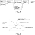
FIG. 1 , such an electronically controlled throttle control device includes: athrottle opening sensor 2 configured to detect an opening of athrottle valve 1 as a throttle opening signal; an electronic control unit (ECU) 5 configured to calculate a throttle opening command signal in response to an operation status of a vehicle and calculate a control output command signal for opening and closing thethrottle valve 1 provided in anintake conduit 4 of athrottle body 3 to a target opening position based on the throttle opening command and the throttle opening signal; and anactuator 6 configured to open and close thethrottle valve 1 by a control output command signal output from the electronic control unit (ECU) 5. As illustrated inFIG. 4 , the control output command signal calculated by the electronic control unit (ECU) is calculated based on a throttle main control command, calculated from a throttle opening deviation which is a difference between the throttle opening command and the throttle opening signal, and a throttle correction control command which is a value obtained by integrating a product of the throttle opening deviation and a coefficient. - However, the above-described conventional electronically controlled throttle control device calculates the integral during the entire period in which the throttle valve is driven so that excessive throttle correction control command is caused by the influence of a large throttle opening deviation.
- Therefore, there is a problem that the throttle easily overshoots with respect to the throttle opening command as illustrated in
FIG. 5 . In addition, there is also a problem that the convergence time of the throttle opening increases due to the occurrence of overshoot.
JP H10 288052 A
JP H11 351033 A
EP 1 308 615 A2 discloses an electronic throttle control apparatus with an electronic throttle including a throttle valve which is opened and closed by a motor, and a microcomputer which controls the motor.
JP H09 42032 A - The present invention has been made by focusing on the problems of the conventional electronically controlled throttle control device, and an object thereof is not only to prevent overshooting of a throttle with respect to a throttle opening command but also to shorten the convergence time of throttle opening.
- An electronically controlled throttle control device is provided according to
claim 1. - According to the present invention, it is possible to not only prevent overshooting of the throttle with respect to the throttle opening command but also to shorten the convergence time of the throttle opening.
-
-
FIG. 1 is a schematic diagram illustrating a configuration of an electronically controlled throttle control device according to a preferred embodiment of the present invention and a conventional example; -
FIG. 2 is a block diagram illustrating a control output command signal calculation unit according to the embodiment illustrated inFIG. 1 ; -
FIG. 3 is a relationship diagram illustrating temporal changes of a throttle opening deviation and a correction control command according to the embodiment illustrated inFIG. 1 ; -
FIG. 4 is a block diagram illustrating a control output command signal calculation unit according to the conventional example illustrated inFIG. 1 ; and -
FIG. 5 is a relationship diagram illustrating temporal changes of a throttle opening deviation and a correction control command according to the conventional example illustrated inFIG. 1 . - Hereinafter, an embodiment for carrying out the present invention will be described with reference to the drawings.
-
FIG. 1 illustrates a preferred embodiment of an electronically controlled throttle control device according to the present invention, and the overall is substantially the same as that of a conventional example. The electronically controlled throttle control device is similar to the conventional example in terms of including athrottle opening sensor 2 configured to detect an opening of athrottle valve 1 as a throttle opening signal; an electronic control unit (ECU) 5 configured to calculate a throttle opening command signal in response to an operation status of a vehicle and calculate a control output command signal for opening and closing thethrottle valve 1 provided in anintake conduit 4 of athrottle body 3 to a target opening position based on the throttle opening command and the throttle opening signal; and anactuator 6 configured to open and close the throttle by a control output command signal output from the electronic control unit (ECU) 5, and the control output command calculated by the electronic control unit (ECU) being calculated based on a throttle main control command, calculated from a throttle opening deviation which is a difference between the throttle opening command and the throttle opening signal, and a throttle correction control command which is a value obtained by integrating a product of the throttle opening deviation and a coefficient as illustrated inFIG. 2 . - In particular, a difference from
FIG. 4 according to the conventional example is that a value of the coefficient used at the time of calculating the throttle correction control command is changed depending on a driving state of the throttle. Specifically, the throttle driving state is set such that a case where the throttle opening deviation is positive and a throttle main control command value is positive or a case where the throttle opening deviation is negative and the throttle main control command value is negative is set as a throttle acceleration state is set, and other cases are set as a throttle deceleration state. In addition, a case where the throttle opening approaches the opening command and the opening deviation becomes equal to or smaller than a certain value is set as a small deviation state. - Further, the value of the coefficient used at the time of performing the integral calculation is set depending on the three states such that the coefficient is set to be small in the acceleration state, to a medium value in the deceleration state, and to be large in the small deviation state, and the throttle correction control command is obtained. The control output command signal is calculated from the obtained main control command and the correction control command in consideration of the throttle driving state, and the throttle is driven.
- As a result, it is possible to reduce the influence on the correction control command when the opening deviation is large by changing the coefficient at the time of integrating the throttle opening deviation and a temporal change of the correction control command in the throttle driving state as illustrated in
FIG. 3 . Accordingly, the correction control command is not excessively generated, and thus, the throttle is less likely to overshoot. In addition, the opening deviation can be made quickly approach the opening instruction when the opening deviation becomes small, and thus, the convergence time of the throttle opening is shortened.
Claims (1)
- An electronically controlled throttle control device comprising: a throttle opening sensor (2) configured to detect an opening of a throttle valve (1) as a throttle opening signal; an electronic control unit (ECU) (5) configured to calculate a throttle opening command in response to an operation status of a vehicle and calculate a control output command for opening and closing the throttle valve (1) provided in an intake conduit (4) of a throttle body (3) to a target opening position based on the throttle opening command and the throttle opening signal; and an actuator (6) configured to open and close the throttle valve (1) by a control output command signal output from the electronic control unit (ECU) (5),the control output command calculated by the electronic control unit (ECU) (5) being calculated based on a throttle main control command, calculated from a throttle opening deviation which is a difference between the throttle opening command and the throttle opening signal, and a throttle correction control command which is a value obtained by integrating a product of the throttle opening deviation and a coefficient,wherein the coefficient for calculation of the throttle correction control command is changed depending on a driving state of the throttle valve (1), characterised in that a case where the throttle opening deviation and the throttle main control command are both positive and a case where the throttle opening deviation and the throttle main control command are both negative is set as an acceleration state, a case where the throttle opening deviation falls below a certain value is set as a small opening deviation state, and other cases are set as a deceleration state,wherein the value of the coefficient is set depending on the acceleration state, the small opening deviation state and the deceleration state such that the coefficient is set to be small in the acceleration state, to a medium value in the deceleration state, and to be large in the small opening deviation state.
Applications Claiming Priority (1)
| Application Number | Priority Date | Filing Date | Title |
|---|---|---|---|
| JP2019043601A JP7266856B2 (en) | 2019-03-11 | 2019-03-11 | Electronically controlled throttle controller |
Publications (2)
| Publication Number | Publication Date |
|---|---|
| EP3708813A1 EP3708813A1 (en) | 2020-09-16 |
| EP3708813B1 true EP3708813B1 (en) | 2023-10-18 |
Family
ID=69770689
Family Applications (1)
| Application Number | Title | Priority Date | Filing Date |
|---|---|---|---|
| EP20161040.9A Active EP3708813B1 (en) | 2019-03-11 | 2020-03-04 | Electronically controlled throttle control device |
Country Status (6)
| Country | Link |
|---|---|
| US (1) | US10927769B2 (en) |
| EP (1) | EP3708813B1 (en) |
| JP (1) | JP7266856B2 (en) |
| CN (1) | CN111677590B (en) |
| AU (1) | AU2020201740A1 (en) |
| RU (1) | RU2020109666A (en) |
Families Citing this family (2)
| Publication number | Priority date | Publication date | Assignee | Title |
|---|---|---|---|---|
| JP7777323B2 (en) | 2021-08-02 | 2025-11-28 | 株式会社ニッキ | Electronic throttle control method and electronic throttle control device |
| JP2025068847A (en) * | 2023-10-17 | 2025-04-30 | 株式会社ニッキ | Electronic control method for throttle and electronically controlled throttle device |
Family Cites Families (20)
| Publication number | Priority date | Publication date | Assignee | Title |
|---|---|---|---|---|
| US5151861A (en) * | 1989-02-22 | 1992-09-29 | Mitsubishi Jidosha Kogyo Kabushiki Kaisha | Vehicle engine output control method and vehicle engine |
| JPH04303146A (en) * | 1991-03-30 | 1992-10-27 | Mazda Motor Corp | Fuel controlling device for engine |
| JP3139811B2 (en) | 1992-02-28 | 2001-03-05 | 株式会社日立製作所 | Engine control device |
| JP2927212B2 (en) * | 1995-07-31 | 1999-07-28 | 株式会社デンソー | Throttle control device for internal combustion engine |
| JP3356945B2 (en) * | 1996-12-17 | 2002-12-16 | 愛三工業株式会社 | Throttle valve control device |
| JPH10288052A (en) * | 1997-04-15 | 1998-10-27 | Hitachi Ltd | Throttle valve control device |
| JPH11117771A (en) * | 1997-10-16 | 1999-04-27 | Denso Corp | Throttle control device for internal combustion engine |
| JPH11351033A (en) * | 1998-06-05 | 1999-12-21 | Aisan Ind Co Ltd | Throttle control system |
| MY138476A (en) * | 2001-02-01 | 2009-06-30 | Honda Motor Co Ltd | Apparatus for and method of controlling plant |
| JP3826014B2 (en) * | 2001-11-02 | 2006-09-27 | 愛三工業株式会社 | Electronic throttle control device |
| JP3863008B2 (en) * | 2001-11-20 | 2006-12-27 | 本田技研工業株式会社 | Output control device for internal combustion engine |
| JP3980424B2 (en) * | 2002-07-03 | 2007-09-26 | 本田技研工業株式会社 | Air-fuel ratio control device for internal combustion engine |
| JP4391275B2 (en) * | 2004-03-09 | 2009-12-24 | 三菱電機株式会社 | Multi-cylinder engine operation control device |
| JP4355261B2 (en) * | 2004-06-09 | 2009-10-28 | 三菱電機株式会社 | Throttle control device for internal combustion engine |
| JP4635924B2 (en) * | 2006-03-22 | 2011-02-23 | 株式会社デンソー | Intake module |
| JP2008038872A (en) | 2006-08-10 | 2008-02-21 | Nikki Co Ltd | Electronic control method of throttle and electronic control throttle device |
| JP2008204125A (en) * | 2007-02-20 | 2008-09-04 | Mikuni Corp | Electronic control device and feedback control method |
| JP5020361B2 (en) * | 2010-09-08 | 2012-09-05 | 三菱電機株式会社 | Engine fuel injection control device |
| KR101198794B1 (en) * | 2010-09-14 | 2012-11-07 | 현대자동차주식회사 | System and method for controlling fuel injection |
| KR101198793B1 (en) * | 2010-09-14 | 2012-11-07 | 현대자동차주식회사 | System and method for controlling the number of pilot injections |
-
2019
- 2019-03-11 JP JP2019043601A patent/JP7266856B2/en active Active
-
2020
- 2020-03-04 EP EP20161040.9A patent/EP3708813B1/en active Active
- 2020-03-05 RU RU2020109666A patent/RU2020109666A/en unknown
- 2020-03-06 CN CN202010151146.1A patent/CN111677590B/en active Active
- 2020-03-10 US US16/814,973 patent/US10927769B2/en active Active
- 2020-03-10 AU AU2020201740A patent/AU2020201740A1/en not_active Abandoned
Also Published As
| Publication number | Publication date |
|---|---|
| US20200291873A1 (en) | 2020-09-17 |
| RU2020109666A (en) | 2021-09-07 |
| CN111677590A (en) | 2020-09-18 |
| JP7266856B2 (en) | 2023-05-01 |
| CN111677590B (en) | 2024-05-07 |
| JP2020148094A (en) | 2020-09-17 |
| US10927769B2 (en) | 2021-02-23 |
| EP3708813A1 (en) | 2020-09-16 |
| AU2020201740A1 (en) | 2020-10-01 |
Similar Documents
| Publication | Publication Date | Title |
|---|---|---|
| US9915211B2 (en) | Abnormality diagnosis device and abnormality diagnosis method for supercharger | |
| US6494181B2 (en) | Unit for controlling electronically controlled throttle valve | |
| US5706782A (en) | Engine control system | |
| US10352258B2 (en) | Control device for internal combustion engine having supercharger | |
| US9541016B2 (en) | Throttle control device for internal combustion engine and throttle control method for internal combustion engine | |
| EP3708813B1 (en) | Electronically controlled throttle control device | |
| EP3279454A1 (en) | Control device for internal combustion engine | |
| US5355972A (en) | Control device for a sucked air quantity of an engine | |
| GB2294337A (en) | IC engine idling control | |
| EP1081358B1 (en) | Throttle controlling device | |
| JPS62153523A (en) | Supercharged pressure control device for engine with turbocharger | |
| JPS644062B2 (en) | ||
| US7527027B2 (en) | Abnormality determination apparatus for intake amount control mechanism | |
| JPH0774625B2 (en) | Control device for internal combustion engine | |
| EP1710420B1 (en) | Control apparatus for internal combustion engine | |
| HK40035908A (en) | Electronically controlled throttle control device | |
| JP3294894B2 (en) | Evacuation traveling device for vehicles | |
| JPH0666187A (en) | Method and device for controlling actuator for car | |
| HK40035908B (en) | Electronically controlled throttle control device | |
| JP2563433Y2 (en) | Throttle opening control device for in-vehicle internal combustion engine | |
| JP2000205053A (en) | EGR control device | |
| JP2000179363A (en) | Fuel injection amount control device when electronically controlled throttle valve is abnormal | |
| JPH04241735A (en) | Supercharging pressure control method of turbocharger | |
| JPH0514545U (en) | Idle speed control device for internal combustion engine | |
| JPS5862336A (en) | Control device of number of idling revolution in internal-combustion engine |
Legal Events
| Date | Code | Title | Description |
|---|---|---|---|
| PUAI | Public reference made under article 153(3) epc to a published international application that has entered the european phase |
Free format text: ORIGINAL CODE: 0009012 |
|
| STAA | Information on the status of an ep patent application or granted ep patent |
Free format text: STATUS: THE APPLICATION HAS BEEN PUBLISHED |
|
| AK | Designated contracting states |
Kind code of ref document: A1 Designated state(s): AL AT BE BG CH CY CZ DE DK EE ES FI FR GB GR HR HU IE IS IT LI LT LU LV MC MK MT NL NO PL PT RO RS SE SI SK SM TR |
|
| AX | Request for extension of the european patent |
Extension state: BA ME |
|
| STAA | Information on the status of an ep patent application or granted ep patent |
Free format text: STATUS: REQUEST FOR EXAMINATION WAS MADE |
|
| 17P | Request for examination filed |
Effective date: 20210226 |
|
| RAX | Requested extension states of the european patent have changed |
Extension state: BA Payment date: 20210226 Extension state: ME Payment date: 20210226 |
|
| RBV | Designated contracting states (corrected) |
Designated state(s): AL AT BE BG CH CY CZ DE DK EE ES FI FR GB GR HR HU IE IS IT LI LT LU LV MC MK MT NL NO PL PT RO RS SE SI SK SM TR |
|
| GRAP | Despatch of communication of intention to grant a patent |
Free format text: ORIGINAL CODE: EPIDOSNIGR1 |
|
| STAA | Information on the status of an ep patent application or granted ep patent |
Free format text: STATUS: GRANT OF PATENT IS INTENDED |
|
| INTG | Intention to grant announced |
Effective date: 20221128 |
|
| GRAJ | Information related to disapproval of communication of intention to grant by the applicant or resumption of examination proceedings by the epo deleted |
Free format text: ORIGINAL CODE: EPIDOSDIGR1 |
|
| STAA | Information on the status of an ep patent application or granted ep patent |
Free format text: STATUS: REQUEST FOR EXAMINATION WAS MADE |
|
| INTC | Intention to grant announced (deleted) | ||
| GRAP | Despatch of communication of intention to grant a patent |
Free format text: ORIGINAL CODE: EPIDOSNIGR1 |
|
| STAA | Information on the status of an ep patent application or granted ep patent |
Free format text: STATUS: GRANT OF PATENT IS INTENDED |
|
| INTG | Intention to grant announced |
Effective date: 20230511 |
|
| GRAS | Grant fee paid |
Free format text: ORIGINAL CODE: EPIDOSNIGR3 |
|
| GRAA | (expected) grant |
Free format text: ORIGINAL CODE: 0009210 |
|
| STAA | Information on the status of an ep patent application or granted ep patent |
Free format text: STATUS: THE PATENT HAS BEEN GRANTED |
|
| AK | Designated contracting states |
Kind code of ref document: B1 Designated state(s): AL AT BE BG CH CY CZ DE DK EE ES FI FR GB GR HR HU IE IS IT LI LT LU LV MC MK MT NL NO PL PT RO RS SE SI SK SM TR |
|
| REG | Reference to a national code |
Ref country code: GB Ref legal event code: FG4D |
|
| REG | Reference to a national code |
Ref country code: CH Ref legal event code: EP |
|
| REG | Reference to a national code |
Ref country code: DE Ref legal event code: R096 Ref document number: 602020019303 Country of ref document: DE |
|
| REG | Reference to a national code |
Ref country code: IE Ref legal event code: FG4D |
|
| REG | Reference to a national code |
Ref country code: LT Ref legal event code: MG9D |
|
| REG | Reference to a national code |
Ref country code: NL Ref legal event code: MP Effective date: 20231018 |
|
| REG | Reference to a national code |
Ref country code: AT Ref legal event code: MK05 Ref document number: 1622679 Country of ref document: AT Kind code of ref document: T Effective date: 20231018 |
|
| PG25 | Lapsed in a contracting state [announced via postgrant information from national office to epo] |
Ref country code: NL Free format text: LAPSE BECAUSE OF FAILURE TO SUBMIT A TRANSLATION OF THE DESCRIPTION OR TO PAY THE FEE WITHIN THE PRESCRIBED TIME-LIMIT Effective date: 20231018 |
|
| PG25 | Lapsed in a contracting state [announced via postgrant information from national office to epo] |
Ref country code: GR Free format text: LAPSE BECAUSE OF FAILURE TO SUBMIT A TRANSLATION OF THE DESCRIPTION OR TO PAY THE FEE WITHIN THE PRESCRIBED TIME-LIMIT Effective date: 20240119 |
|
| PG25 | Lapsed in a contracting state [announced via postgrant information from national office to epo] |
Ref country code: IS Free format text: LAPSE BECAUSE OF FAILURE TO SUBMIT A TRANSLATION OF THE DESCRIPTION OR TO PAY THE FEE WITHIN THE PRESCRIBED TIME-LIMIT Effective date: 20240218 |
|
| PG25 | Lapsed in a contracting state [announced via postgrant information from national office to epo] |
Ref country code: LT Free format text: LAPSE BECAUSE OF FAILURE TO SUBMIT A TRANSLATION OF THE DESCRIPTION OR TO PAY THE FEE WITHIN THE PRESCRIBED TIME-LIMIT Effective date: 20231018 |
|
| PG25 | Lapsed in a contracting state [announced via postgrant information from national office to epo] |
Ref country code: AT Free format text: LAPSE BECAUSE OF FAILURE TO SUBMIT A TRANSLATION OF THE DESCRIPTION OR TO PAY THE FEE WITHIN THE PRESCRIBED TIME-LIMIT Effective date: 20231018 |
|
| PG25 | Lapsed in a contracting state [announced via postgrant information from national office to epo] |
Ref country code: ES Free format text: LAPSE BECAUSE OF FAILURE TO SUBMIT A TRANSLATION OF THE DESCRIPTION OR TO PAY THE FEE WITHIN THE PRESCRIBED TIME-LIMIT Effective date: 20231018 |
|
| PG25 | Lapsed in a contracting state [announced via postgrant information from national office to epo] |
Ref country code: LT Free format text: LAPSE BECAUSE OF FAILURE TO SUBMIT A TRANSLATION OF THE DESCRIPTION OR TO PAY THE FEE WITHIN THE PRESCRIBED TIME-LIMIT Effective date: 20231018 Ref country code: IS Free format text: LAPSE BECAUSE OF FAILURE TO SUBMIT A TRANSLATION OF THE DESCRIPTION OR TO PAY THE FEE WITHIN THE PRESCRIBED TIME-LIMIT Effective date: 20240218 Ref country code: GR Free format text: LAPSE BECAUSE OF FAILURE TO SUBMIT A TRANSLATION OF THE DESCRIPTION OR TO PAY THE FEE WITHIN THE PRESCRIBED TIME-LIMIT Effective date: 20240119 Ref country code: ES Free format text: LAPSE BECAUSE OF FAILURE TO SUBMIT A TRANSLATION OF THE DESCRIPTION OR TO PAY THE FEE WITHIN THE PRESCRIBED TIME-LIMIT Effective date: 20231018 Ref country code: BG Free format text: LAPSE BECAUSE OF FAILURE TO SUBMIT A TRANSLATION OF THE DESCRIPTION OR TO PAY THE FEE WITHIN THE PRESCRIBED TIME-LIMIT Effective date: 20240118 Ref country code: AT Free format text: LAPSE BECAUSE OF FAILURE TO SUBMIT A TRANSLATION OF THE DESCRIPTION OR TO PAY THE FEE WITHIN THE PRESCRIBED TIME-LIMIT Effective date: 20231018 Ref country code: PT Free format text: LAPSE BECAUSE OF FAILURE TO SUBMIT A TRANSLATION OF THE DESCRIPTION OR TO PAY THE FEE WITHIN THE PRESCRIBED TIME-LIMIT Effective date: 20240219 |
|
| PG25 | Lapsed in a contracting state [announced via postgrant information from national office to epo] |
Ref country code: SE Free format text: LAPSE BECAUSE OF FAILURE TO SUBMIT A TRANSLATION OF THE DESCRIPTION OR TO PAY THE FEE WITHIN THE PRESCRIBED TIME-LIMIT Effective date: 20231018 Ref country code: RS Free format text: LAPSE BECAUSE OF FAILURE TO SUBMIT A TRANSLATION OF THE DESCRIPTION OR TO PAY THE FEE WITHIN THE PRESCRIBED TIME-LIMIT Effective date: 20231018 Ref country code: PL Free format text: LAPSE BECAUSE OF FAILURE TO SUBMIT A TRANSLATION OF THE DESCRIPTION OR TO PAY THE FEE WITHIN THE PRESCRIBED TIME-LIMIT Effective date: 20231018 Ref country code: NO Free format text: LAPSE BECAUSE OF FAILURE TO SUBMIT A TRANSLATION OF THE DESCRIPTION OR TO PAY THE FEE WITHIN THE PRESCRIBED TIME-LIMIT Effective date: 20240118 Ref country code: LV Free format text: LAPSE BECAUSE OF FAILURE TO SUBMIT A TRANSLATION OF THE DESCRIPTION OR TO PAY THE FEE WITHIN THE PRESCRIBED TIME-LIMIT Effective date: 20231018 Ref country code: HR Free format text: LAPSE BECAUSE OF FAILURE TO SUBMIT A TRANSLATION OF THE DESCRIPTION OR TO PAY THE FEE WITHIN THE PRESCRIBED TIME-LIMIT Effective date: 20231018 |
|
| PG25 | Lapsed in a contracting state [announced via postgrant information from national office to epo] |
Ref country code: DK Free format text: LAPSE BECAUSE OF FAILURE TO SUBMIT A TRANSLATION OF THE DESCRIPTION OR TO PAY THE FEE WITHIN THE PRESCRIBED TIME-LIMIT Effective date: 20231018 |
|
| REG | Reference to a national code |
Ref country code: DE Ref legal event code: R097 Ref document number: 602020019303 Country of ref document: DE |
|
| PG25 | Lapsed in a contracting state [announced via postgrant information from national office to epo] |
Ref country code: CZ Free format text: LAPSE BECAUSE OF FAILURE TO SUBMIT A TRANSLATION OF THE DESCRIPTION OR TO PAY THE FEE WITHIN THE PRESCRIBED TIME-LIMIT Effective date: 20231018 |
|
| PG25 | Lapsed in a contracting state [announced via postgrant information from national office to epo] |
Ref country code: SK Free format text: LAPSE BECAUSE OF FAILURE TO SUBMIT A TRANSLATION OF THE DESCRIPTION OR TO PAY THE FEE WITHIN THE PRESCRIBED TIME-LIMIT Effective date: 20231018 |
|
| PG25 | Lapsed in a contracting state [announced via postgrant information from national office to epo] |
Ref country code: SM Free format text: LAPSE BECAUSE OF FAILURE TO SUBMIT A TRANSLATION OF THE DESCRIPTION OR TO PAY THE FEE WITHIN THE PRESCRIBED TIME-LIMIT Effective date: 20231018 Ref country code: SK Free format text: LAPSE BECAUSE OF FAILURE TO SUBMIT A TRANSLATION OF THE DESCRIPTION OR TO PAY THE FEE WITHIN THE PRESCRIBED TIME-LIMIT Effective date: 20231018 Ref country code: RO Free format text: LAPSE BECAUSE OF FAILURE TO SUBMIT A TRANSLATION OF THE DESCRIPTION OR TO PAY THE FEE WITHIN THE PRESCRIBED TIME-LIMIT Effective date: 20231018 Ref country code: IT Free format text: LAPSE BECAUSE OF FAILURE TO SUBMIT A TRANSLATION OF THE DESCRIPTION OR TO PAY THE FEE WITHIN THE PRESCRIBED TIME-LIMIT Effective date: 20231018 Ref country code: EE Free format text: LAPSE BECAUSE OF FAILURE TO SUBMIT A TRANSLATION OF THE DESCRIPTION OR TO PAY THE FEE WITHIN THE PRESCRIBED TIME-LIMIT Effective date: 20231018 Ref country code: DK Free format text: LAPSE BECAUSE OF FAILURE TO SUBMIT A TRANSLATION OF THE DESCRIPTION OR TO PAY THE FEE WITHIN THE PRESCRIBED TIME-LIMIT Effective date: 20231018 Ref country code: CZ Free format text: LAPSE BECAUSE OF FAILURE TO SUBMIT A TRANSLATION OF THE DESCRIPTION OR TO PAY THE FEE WITHIN THE PRESCRIBED TIME-LIMIT Effective date: 20231018 |
|
| PLBE | No opposition filed within time limit |
Free format text: ORIGINAL CODE: 0009261 |
|
| STAA | Information on the status of an ep patent application or granted ep patent |
Free format text: STATUS: NO OPPOSITION FILED WITHIN TIME LIMIT |
|
| 26N | No opposition filed |
Effective date: 20240719 |
|
| REG | Reference to a national code |
Ref country code: DE Ref legal event code: R119 Ref document number: 602020019303 Country of ref document: DE |
|
| PG25 | Lapsed in a contracting state [announced via postgrant information from national office to epo] |
Ref country code: SI Free format text: LAPSE BECAUSE OF FAILURE TO SUBMIT A TRANSLATION OF THE DESCRIPTION OR TO PAY THE FEE WITHIN THE PRESCRIBED TIME-LIMIT Effective date: 20231018 |
|
| PG25 | Lapsed in a contracting state [announced via postgrant information from national office to epo] |
Ref country code: SI Free format text: LAPSE BECAUSE OF FAILURE TO SUBMIT A TRANSLATION OF THE DESCRIPTION OR TO PAY THE FEE WITHIN THE PRESCRIBED TIME-LIMIT Effective date: 20231018 |
|
| REG | Reference to a national code |
Ref country code: CH Ref legal event code: PL |
|
| PG25 | Lapsed in a contracting state [announced via postgrant information from national office to epo] |
Ref country code: LU Free format text: LAPSE BECAUSE OF NON-PAYMENT OF DUE FEES Effective date: 20240304 |
|
| PG25 | Lapsed in a contracting state [announced via postgrant information from national office to epo] |
Ref country code: MC Free format text: LAPSE BECAUSE OF FAILURE TO SUBMIT A TRANSLATION OF THE DESCRIPTION OR TO PAY THE FEE WITHIN THE PRESCRIBED TIME-LIMIT Effective date: 20231018 |
|
| PG25 | Lapsed in a contracting state [announced via postgrant information from national office to epo] |
Ref country code: MC Free format text: LAPSE BECAUSE OF FAILURE TO SUBMIT A TRANSLATION OF THE DESCRIPTION OR TO PAY THE FEE WITHIN THE PRESCRIBED TIME-LIMIT Effective date: 20231018 Ref country code: LU Free format text: LAPSE BECAUSE OF NON-PAYMENT OF DUE FEES Effective date: 20240304 |
|
| REG | Reference to a national code |
Ref country code: BE Ref legal event code: MM Effective date: 20240331 |
|
| PG25 | Lapsed in a contracting state [announced via postgrant information from national office to epo] |
Ref country code: DE Free format text: LAPSE BECAUSE OF NON-PAYMENT OF DUE FEES Effective date: 20241001 |
|
| PG25 | Lapsed in a contracting state [announced via postgrant information from national office to epo] |
Ref country code: BE Free format text: LAPSE BECAUSE OF NON-PAYMENT OF DUE FEES Effective date: 20240331 |
|
| PG25 | Lapsed in a contracting state [announced via postgrant information from national office to epo] |
Ref country code: FR Free format text: LAPSE BECAUSE OF NON-PAYMENT OF DUE FEES Effective date: 20240331 |
|
| PG25 | Lapsed in a contracting state [announced via postgrant information from national office to epo] |
Ref country code: IE Free format text: LAPSE BECAUSE OF NON-PAYMENT OF DUE FEES Effective date: 20240304 |
|
| PG25 | Lapsed in a contracting state [announced via postgrant information from national office to epo] |
Ref country code: IE Free format text: LAPSE BECAUSE OF NON-PAYMENT OF DUE FEES Effective date: 20240304 Ref country code: FR Free format text: LAPSE BECAUSE OF NON-PAYMENT OF DUE FEES Effective date: 20240331 Ref country code: DE Free format text: LAPSE BECAUSE OF NON-PAYMENT OF DUE FEES Effective date: 20241001 Ref country code: BE Free format text: LAPSE BECAUSE OF NON-PAYMENT OF DUE FEES Effective date: 20240331 Ref country code: CH Free format text: LAPSE BECAUSE OF NON-PAYMENT OF DUE FEES Effective date: 20240331 |
|
| PG25 | Lapsed in a contracting state [announced via postgrant information from national office to epo] |
Ref country code: CY Free format text: LAPSE BECAUSE OF FAILURE TO SUBMIT A TRANSLATION OF THE DESCRIPTION OR TO PAY THE FEE WITHIN THE PRESCRIBED TIME-LIMIT; INVALID AB INITIO Effective date: 20200304 |
|
| PG25 | Lapsed in a contracting state [announced via postgrant information from national office to epo] |
Ref country code: HU Free format text: LAPSE BECAUSE OF FAILURE TO SUBMIT A TRANSLATION OF THE DESCRIPTION OR TO PAY THE FEE WITHIN THE PRESCRIBED TIME-LIMIT; INVALID AB INITIO Effective date: 20200304 |
|
| PG25 | Lapsed in a contracting state [announced via postgrant information from national office to epo] |
Ref country code: FI Free format text: LAPSE BECAUSE OF FAILURE TO SUBMIT A TRANSLATION OF THE DESCRIPTION OR TO PAY THE FEE WITHIN THE PRESCRIBED TIME-LIMIT Effective date: 20231019 |
|
| PG25 | Lapsed in a contracting state [announced via postgrant information from national office to epo] |
Ref country code: TR Free format text: LAPSE BECAUSE OF FAILURE TO SUBMIT A TRANSLATION OF THE DESCRIPTION OR TO PAY THE FEE WITHIN THE PRESCRIBED TIME-LIMIT Effective date: 20231018 |
|
| PGFP | Annual fee paid to national office [announced via postgrant information from national office to epo] |
Ref country code: GB Payment date: 20260216 Year of fee payment: 7 |