EP3708809B1 - Heat exchanger suspension system - Google Patents
Heat exchanger suspension system Download PDFInfo
- Publication number
- EP3708809B1 EP3708809B1 EP20165335.9A EP20165335A EP3708809B1 EP 3708809 B1 EP3708809 B1 EP 3708809B1 EP 20165335 A EP20165335 A EP 20165335A EP 3708809 B1 EP3708809 B1 EP 3708809B1
- Authority
- EP
- European Patent Office
- Prior art keywords
- heat exchanger
- various embodiments
- engine
- gas
- pipes
- Prior art date
- Legal status (The legal status is an assumption and is not a legal conclusion. Google has not performed a legal analysis and makes no representation as to the accuracy of the status listed.)
- Active
Links
Images



Classifications
-
- F—MECHANICAL ENGINEERING; LIGHTING; HEATING; WEAPONS; BLASTING
- F02—COMBUSTION ENGINES; HOT-GAS OR COMBUSTION-PRODUCT ENGINE PLANTS
- F02C—GAS-TURBINE PLANTS; AIR INTAKES FOR JET-PROPULSION PLANTS; CONTROLLING FUEL SUPPLY IN AIR-BREATHING JET-PROPULSION PLANTS
- F02C7/00—Features, components parts, details or accessories, not provided for in, or of interest apart form groups F02C1/00 - F02C6/00; Air intakes for jet-propulsion plants
- F02C7/32—Arrangement, mounting, or driving, of auxiliaries
-
- F—MECHANICAL ENGINEERING; LIGHTING; HEATING; WEAPONS; BLASTING
- F02—COMBUSTION ENGINES; HOT-GAS OR COMBUSTION-PRODUCT ENGINE PLANTS
- F02C—GAS-TURBINE PLANTS; AIR INTAKES FOR JET-PROPULSION PLANTS; CONTROLLING FUEL SUPPLY IN AIR-BREATHING JET-PROPULSION PLANTS
- F02C6/00—Plural gas-turbine plants; Combinations of gas-turbine plants with other apparatus; Adaptations of gas-turbine plants for special use
- F02C6/04—Gas-turbine plants providing heated or pressurised working fluid for other apparatus, e.g. without mechanical power output
- F02C6/06—Gas-turbine plants providing heated or pressurised working fluid for other apparatus, e.g. without mechanical power output providing compressed gas
- F02C6/08—Gas-turbine plants providing heated or pressurised working fluid for other apparatus, e.g. without mechanical power output providing compressed gas the gas being bled from the gas-turbine compressor
-
- F—MECHANICAL ENGINEERING; LIGHTING; HEATING; WEAPONS; BLASTING
- F02—COMBUSTION ENGINES; HOT-GAS OR COMBUSTION-PRODUCT ENGINE PLANTS
- F02C—GAS-TURBINE PLANTS; AIR INTAKES FOR JET-PROPULSION PLANTS; CONTROLLING FUEL SUPPLY IN AIR-BREATHING JET-PROPULSION PLANTS
- F02C7/00—Features, components parts, details or accessories, not provided for in, or of interest apart form groups F02C1/00 - F02C6/00; Air intakes for jet-propulsion plants
- F02C7/12—Cooling of plants
- F02C7/14—Cooling of plants of fluids in the plant, e.g. lubricant or fuel
- F02C7/141—Cooling of plants of fluids in the plant, e.g. lubricant or fuel of working fluid
-
- F—MECHANICAL ENGINEERING; LIGHTING; HEATING; WEAPONS; BLASTING
- F02—COMBUSTION ENGINES; HOT-GAS OR COMBUSTION-PRODUCT ENGINE PLANTS
- F02C—GAS-TURBINE PLANTS; AIR INTAKES FOR JET-PROPULSION PLANTS; CONTROLLING FUEL SUPPLY IN AIR-BREATHING JET-PROPULSION PLANTS
- F02C7/00—Features, components parts, details or accessories, not provided for in, or of interest apart form groups F02C1/00 - F02C6/00; Air intakes for jet-propulsion plants
- F02C7/12—Cooling of plants
- F02C7/16—Cooling of plants characterised by cooling medium
- F02C7/18—Cooling of plants characterised by cooling medium the medium being gaseous, e.g. air
- F02C7/185—Cooling means for reducing the temperature of the cooling air or gas
-
- F—MECHANICAL ENGINEERING; LIGHTING; HEATING; WEAPONS; BLASTING
- F02—COMBUSTION ENGINES; HOT-GAS OR COMBUSTION-PRODUCT ENGINE PLANTS
- F02K—JET-PROPULSION PLANTS
- F02K3/00—Plants including a gas turbine driving a compressor or a ducted fan
- F02K3/08—Plants including a gas turbine driving a compressor or a ducted fan with supplementary heating of the working fluid; Control thereof
- F02K3/105—Heating the by-pass flow
- F02K3/115—Heating the by-pass flow by means of indirect heat exchange
-
- F—MECHANICAL ENGINEERING; LIGHTING; HEATING; WEAPONS; BLASTING
- F04—POSITIVE - DISPLACEMENT MACHINES FOR LIQUIDS; PUMPS FOR LIQUIDS OR ELASTIC FLUIDS
- F04D—NON-POSITIVE-DISPLACEMENT PUMPS
- F04D29/00—Details, component parts, or accessories
- F04D29/58—Cooling; Heating; Diminishing heat transfer
- F04D29/582—Cooling; Heating; Diminishing heat transfer specially adapted for elastic fluid pumps
- F04D29/5826—Cooling at least part of the working fluid in a heat exchanger
-
- F—MECHANICAL ENGINEERING; LIGHTING; HEATING; WEAPONS; BLASTING
- F28—HEAT EXCHANGE IN GENERAL
- F28D—HEAT-EXCHANGE APPARATUS, NOT PROVIDED FOR IN ANOTHER SUBCLASS, IN WHICH THE HEAT-EXCHANGE MEDIA DO NOT COME INTO DIRECT CONTACT
- F28D7/00—Heat-exchange apparatus having stationary tubular conduit assemblies for both heat-exchange media, the media being in contact with different sides of a conduit wall
- F28D7/06—Heat-exchange apparatus having stationary tubular conduit assemblies for both heat-exchange media, the media being in contact with different sides of a conduit wall the conduits having a single U-bend
-
- F—MECHANICAL ENGINEERING; LIGHTING; HEATING; WEAPONS; BLASTING
- F28—HEAT EXCHANGE IN GENERAL
- F28F—DETAILS OF HEAT-EXCHANGE AND HEAT-TRANSFER APPARATUS, OF GENERAL APPLICATION
- F28F9/00—Casings; Header boxes; Auxiliary supports for elements; Auxiliary members within casings
- F28F9/001—Casings in the form of plate-like arrangements; Frames enclosing a heat exchange core
- F28F9/002—Casings in the form of plate-like arrangements; Frames enclosing a heat exchange core with fastening means for other structures
-
- F—MECHANICAL ENGINEERING; LIGHTING; HEATING; WEAPONS; BLASTING
- F28—HEAT EXCHANGE IN GENERAL
- F28F—DETAILS OF HEAT-EXCHANGE AND HEAT-TRANSFER APPARATUS, OF GENERAL APPLICATION
- F28F9/00—Casings; Header boxes; Auxiliary supports for elements; Auxiliary members within casings
- F28F9/02—Header boxes; End plates
- F28F9/0246—Arrangements for connecting header boxes with flow lines
-
- F—MECHANICAL ENGINEERING; LIGHTING; HEATING; WEAPONS; BLASTING
- F05—INDEXING SCHEMES RELATING TO ENGINES OR PUMPS IN VARIOUS SUBCLASSES OF CLASSES F01-F04
- F05D—INDEXING SCHEME FOR ASPECTS RELATING TO NON-POSITIVE-DISPLACEMENT MACHINES OR ENGINES, GAS-TURBINES OR JET-PROPULSION PLANTS
- F05D2260/00—Function
- F05D2260/20—Heat transfer, e.g. cooling
- F05D2260/213—Heat transfer, e.g. cooling by the provision of a heat exchanger within the cooling circuit
-
- F—MECHANICAL ENGINEERING; LIGHTING; HEATING; WEAPONS; BLASTING
- F05—INDEXING SCHEMES RELATING TO ENGINES OR PUMPS IN VARIOUS SUBCLASSES OF CLASSES F01-F04
- F05D—INDEXING SCHEME FOR ASPECTS RELATING TO NON-POSITIVE-DISPLACEMENT MACHINES OR ENGINES, GAS-TURBINES OR JET-PROPULSION PLANTS
- F05D2300/00—Materials; Properties thereof
- F05D2300/10—Metals, alloys or intermetallic compounds
- F05D2300/17—Alloys
- F05D2300/175—Superalloys
-
- F—MECHANICAL ENGINEERING; LIGHTING; HEATING; WEAPONS; BLASTING
- F28—HEAT EXCHANGE IN GENERAL
- F28D—HEAT-EXCHANGE APPARATUS, NOT PROVIDED FOR IN ANOTHER SUBCLASS, IN WHICH THE HEAT-EXCHANGE MEDIA DO NOT COME INTO DIRECT CONTACT
- F28D21/00—Heat-exchange apparatus not covered by any of the groups F28D1/00 - F28D20/00
- F28D2021/0019—Other heat exchangers for particular applications; Heat exchange systems not otherwise provided for
- F28D2021/0026—Other heat exchangers for particular applications; Heat exchange systems not otherwise provided for for combustion engines, e.g. for gas turbines or for Stirling engines
-
- F—MECHANICAL ENGINEERING; LIGHTING; HEATING; WEAPONS; BLASTING
- F28—HEAT EXCHANGE IN GENERAL
- F28F—DETAILS OF HEAT-EXCHANGE AND HEAT-TRANSFER APPARATUS, OF GENERAL APPLICATION
- F28F2255/00—Heat exchanger elements made of materials having special features or resulting from particular manufacturing processes
- F28F2255/02—Flexible elements
-
- F—MECHANICAL ENGINEERING; LIGHTING; HEATING; WEAPONS; BLASTING
- F28—HEAT EXCHANGE IN GENERAL
- F28F—DETAILS OF HEAT-EXCHANGE AND HEAT-TRANSFER APPARATUS, OF GENERAL APPLICATION
- F28F2265/00—Safety or protection arrangements; Arrangements for preventing malfunction
- F28F2265/26—Safety or protection arrangements; Arrangements for preventing malfunction for allowing differential expansion between elements
-
- F—MECHANICAL ENGINEERING; LIGHTING; HEATING; WEAPONS; BLASTING
- F28—HEAT EXCHANGE IN GENERAL
- F28F—DETAILS OF HEAT-EXCHANGE AND HEAT-TRANSFER APPARATUS, OF GENERAL APPLICATION
- F28F2280/00—Mounting arrangements; Arrangements for facilitating assembling or disassembling of heat exchanger parts
-
- Y—GENERAL TAGGING OF NEW TECHNOLOGICAL DEVELOPMENTS; GENERAL TAGGING OF CROSS-SECTIONAL TECHNOLOGIES SPANNING OVER SEVERAL SECTIONS OF THE IPC; TECHNICAL SUBJECTS COVERED BY FORMER USPC CROSS-REFERENCE ART COLLECTIONS [XRACs] AND DIGESTS
- Y02—TECHNOLOGIES OR APPLICATIONS FOR MITIGATION OR ADAPTATION AGAINST CLIMATE CHANGE
- Y02T—CLIMATE CHANGE MITIGATION TECHNOLOGIES RELATED TO TRANSPORTATION
- Y02T50/00—Aeronautics or air transport
- Y02T50/60—Efficient propulsion technologies, e.g. for aircraft
Definitions
- the present disclosure relates to gas turbine engines, and, more specifically, to heat exchangers (HEX) for cooling air of gas turbine engines.
- HEX heat exchangers
- HEX heat exchanger
- a prior art heat exchanger arrangement for a gas turbine engine having the features of the preamble to claim 1 is disclosed in US 3,968,834 .
- a similar prior art heat exchanger arrangement for a gas turbine engine is also disclosed in US 5,243,815 .
- the present invention provides a heat exchanger arrangement for a gas turbine engine according to claim 1.
- any reference to attached, fixed, connected or the like may include permanent, removable, temporary, partial, full and/or any other possible attachment option. Additionally, any reference to without contact (or similar phrases) may also include reduced contact or minimal contact. Surface shading lines may be used throughout the figures to denote different parts but not necessarily to denote the same or different materials. In some cases, reference coordinates may be specific to each figure.
- tail refers to the direction associated with the tail (e.g., the back end) of an aircraft, or generally, to the direction of exhaust of the gas turbine.
- forward refers to the direction associated with the nose (e.g., the front end) of an aircraft, or generally, to the direction of flight or motion.
- gas and “air” may be used interchangeably.
- Fuel efficiency of gas turbine engines is known to be proportional to the ratio of the exit pressure and the inlet pressure of the engine, or overall pressure ratio (OPR). As the OPR increases, the efficiency of the engine generally increases. However, a byproduct of OPR is high operating temperatures in various portions of the engine, such as the high pressure compressor for example. Materials used in gas turbine engines have temperature thresholds which cannot be surpassed for successful operation. Cooling air may be used to decrease operating temperatures of various components in a gas turbine engine. Generally, air from a compressor section of a gas turbine engine is used to cool other sections of the engine. However, as the OPR of gas turbine engines increases, the air from the compressor section may become increasingly hot. A heat exchanger (HEX) may be used to cool the air from a compressor section, thus providing cooled cooling air.
- HEX heat exchanger
- a heat exchanger for a gas turbine engine may be coupled to an engine case via a mounting system comprising links and via pipes or ducts for routing air for cooling.
- the mounting system may comprise a statically determined mounting system.
- the pipes may comprise a stiffness.
- the pipes may include bends in the pipes which may decrease their stiffness.
- the links may comprise a stiffness.
- the links may each comprise single vector load carriers. The stiffness ratio, or the spring rate ratio between the pipes and the links may be between one percent and thirty percent.
- Gas turbine engine 110 may include core engine 120. Core air flow C flows through core engine 120 and is expelled through exhaust outlet 118 surrounding tail cone 122.
- Core engine 120 drives a fan 114 arranged in a bypass flow path B.
- Air in bypass flow-path B flows in the aft direction (z-direction) along bypass flow-path B.
- At least a portion of bypass flow path B may be defined by nacelle 112 and inner fixed structure (IPS) 126.
- Fan case 132 may surround fan 114. Fan case 132 may be housed within fan nacelle 112.
- nacelle 112 typically comprises two halves which are typically mounted to pylon 270.
- Fan case structure 233 may provide structure for securing gas turbine engine 110 to a pylon 160.
- multiple guide vanes 116 may extend radially between core engine 120 and intermediate case IMC 134.
- Upper bifurcation 144 and lower bifurcation 142 may extend radially between the nacelle 112 and IFS 126 in locations opposite one another to accommodate engine components such as wires and fluids, for example.
- Inner fixed structure 126 surrounds core engine 120 and provides core compartments 128.
- Various components may be provided in core compartment 128 such as fluid conduits and/or a compressed air duct 130, for example.
- Compressed air duct 130 may be under high pressure and may supply compressed cooling air from a compressor stage to a high pressure turbine stage, for example.
- a heat exchanger may be coupled to compressed air duct 130.
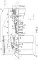
- FIG. 2 elements with like element numbering as depicted in FIG. 1 are intended to be the same and will not necessarily be repeated for the sake of clarity.
- Gas turbine engine 110 may be a two-spool turbofan that generally incorporates a fan section 222, a compressor section 224, a combustor section 226 and a turbine section 228.
- Alternative engines may include, for example, an augmentor section among other systems or features.
- fan section 222 can drive air along a bypass flow-path B while compressor section 224 can drive air along a core flow-path C for compression and communication into combustor section 226 then expansion through turbine section 228.
- turbofan gas turbine engine 110 depicted as a turbofan gas turbine engine 110 herein, it should be understood that the concepts described herein are not limited to use with two-spool turbofans as the teachings may be applied to other types of turbine engines including three-spool architectures.
- Gas turbine engine 110 may generally comprise a low speed spool 230 and a high speed spool 232 mounted for rotation about an engine central longitudinal axis A-A' relative to an engine static structure 236 via one or more bearing systems 238 (shown as bearing system 238-1 and bearing system 238-2 in FIG. 2 ). It should be understood that various bearing systems 238 at various locations may alternatively or additionally be provided including, for example, bearing system 238, bearing system 238-1, and bearing system 238-2.
- Low speed spool 230 may generally comprise an inner shaft 240 that interconnects a fan 114, a low pressure (or first) compressor section 244 and a low pressure (or first) turbine section 246.
- Inner shaft 240 may be connected to fan 114 through a geared architecture 248 that can drive fan 114 at a lower speed than low speed spool 230.
- Geared architecture 248 may comprise a gear assembly 260 enclosed within a gear housing 262.
- Gear assembly 260 couples inner shaft 240 to a rotating fan structure.
- High speed spool 232 may comprise an outer shaft 250 that interconnects a high-pressure compressor (“HPC") 252 (e.g., a second compressor section) and high pressure (or second) turbine section 254.
- HPC high-pressure compressor
- a combustor 256 may be located between HPC 252 and high pressure turbine 254.
- a mid-turbine frame 257 of engine static structure 236 may be located generally between high pressure turbine 254 and low pressure turbine 246.
- Mid-turbine frame 257 may support one or more bearing systems 238 in turbine section 228.
- Inner shaft 240 and outer shaft 250 may be concentric and rotate via bearing systems 23 8 about the engine central longitudinal axis A-A', which is collinear with their longitudinal axes.
- a "high pressure" compressor or turbine experiences a higher pressure than a corresponding "low pressure” compressor or turbine.
- the core airflow C may be compressed by low pressure compressor 244 then HPC 252, mixed and burned with fuel in combustor 256, then expanded over high pressure turbine 254 and low pressure turbine 246.
- Mid-turbine frame 257 includes airfoils 259 which are in the core airflow path.
- Low pressure turbine 246 and high pressure turbine 254 rotationally drive the respective low speed spool 230 and high speed spool 232 in response to the expansion.
- Gas turbine engine 110 may be, for example, a high-bypass geared aircraft engine. In various embodiments, the bypass ratio of gas turbine engine 110 may be greater than about six (6). In various embodiments, the bypass ratio of gas turbine engine 110 may be greater than ten (10).
- geared architecture 248 may be an epicyclic gear train, such as a star gear system (sun gear in meshing engagement with a plurality of star gears supported by a carrier and in meshing engagement with a ring gear) or other gear system. Geared architecture 248 may have a gear reduction ratio of greater than about 2.3 and low pressure turbine 246 may have a pressure ratio that is greater than about 5. In various embodiments, the bypass ratio of gas turbine engine 110 is greater than about ten (10:1).
- the diameter of fan 114 may be significantly larger than that of the low pressure compressor 244, and the low pressure turbine 246 may have a pressure ratio that is greater than about 5:1.
- Low pressure turbine 246 pressure ratio may be measured prior to inlet of low pressure turbine 246 as related to the pressure at the outlet of low pressure turbine 246 prior to an exhaust nozzle.
- FIG. 1 and FIG. 2 provide a general understanding of the sections in a gas turbine engine, and are not intended to limit the disclosure. The present disclosure may extend to all types of turbine engines, including turbofan gas turbine engines and turbojet engines, for all types of applications.
- FIG. 3 elements with like element numbering as depicted in FIG. 1 and FIG. 2 are intended to be the same and will not necessarily be repeated for the sake of clarity.
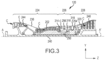
- FIG. 3 illustrates the primary flow gas path through core engine 120, in accordance with various embodiments.
- Core engine 120 may include engine static structure 236, low-pressure compressor 244, high-pressure compressor 252, combustor 256, high-pressure turbine 254, and low-pressure turbine C.
- Engine static structure 236 may be referred to as an engine case.
- Gas may flow into low-pressure compressor 244 along gas path C.
- Gas flowing through low-pressure compressor 244 along gas path C may be compressed, resulting in an increase in pressure and temperature relative to the pressure and temperature upon entering low-pressure compressor 244.
- Gas may flow into high-pressure compressor 252 along gas path C.
- Gas flowing through high-pressure compressor 252 along gas path C may be compressed, resulting in an increase in pressure and temperature relative to the pressure and temperature upon entering high-pressure compressor 252.
- T3 gas Uncombusted gas in gas path C leaving high-pressure compressor 252 may be referred to as T3 gas.
- T3 gas may have a varying temperature at different engine speeds.
- the temperature of T3 gas may be about 400°F (205°C) when core engine 120 is at idle speeds and may reach about 1,400°F (760°C) or higher as core engine 120 accelerates for takeoff, where the term "about” in this context only may refer to +/- 200°F (111°C).
- Different engines may have higher temperatures or lower temperatures at each stage.
- T3 gas may be present at location 314 of core engine 120.
- T3 gas leaving the high-pressure compressor 252 may then flow into combustor 256 to supply combustor 256 with air for combustion.
- uncombusted T3 gas may be mixed with fuel and burned in combustor 256.
- Combusted gas in combustor 256 may be referred to as T4 gas.
- T4 gas may leave combustor 256 and enter high-pressure turbine 254.
- T4 gas may reach or exceed temperatures of up to 3,500°F (1,925°C) or higher.
- T4 gas may be located at location 316, for example.
- T4 gas leaving combustor may follow gas path C to drive high-pressure turbine 254.
- combusted gas that has entered, but not exited, high-pressure turbine 254 may be identified as T4.25 gas.
- T4.25 gas may be significantly cooler than T4 gas exiting combustor 256.
- T4.25 gas may be at temperatures of about 1,000°F-2,000°F (537°C-1,093°C), where the term "about” in this context only may refer to +/- 500°F (278°C).
- T4.25 gas may be located at location 318, for example. The T4.25 gas then follows out high-pressure turbine 254 and into low-pressure turbine 246 along gas path C.
- T4.5 gas combusted gas exiting high-pressure turbine 254 and entering low-pressure turbine 246 may be referred to as T4.5 gas.
- T4.5 gas may be cooler than T4.25 gas found in the high-pressure compressor or T4 gas exiting the combustor.
- T4.5 gas may be about 1,500°F (815°C) degrees at idle, where the term "about” in this context only may refer to +/- 500°F (278°C).
- T4.5 gas may be located at location 320 in gas path C, for example. The T4.5 gas then follows gas path C into low-pressure turbine 246.
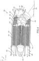
- HEX 400 may comprise a central manifold 410 and a plurality of tubes 430.
- central manifold 410 may comprise an inlet portion 412, a first outlet portion 414, and a second outlet portion 416.
- first outlet portion 414 may be located on the opposite side of inlet portion 412 as second outlet portion 416.
- first outlet portion 414 may be located adjacent to inlet portion 412 (in the positive y-direction).
- second outlet portion 416 may be located adjacent to inlet portion 412 (in the negative y-direction).
- inlet portion 412, first outlet portion 414, and second outlet portion 416 may each individually define a cylindrical void.
- HEX 400 may further comprise a shroud 450.
- shroud 450 may be coupled to central manifold 410.
- Shroud 450 may at least partially encase central manifold 410 and tubes 430.
- a plurality of baffles such as baffle 436 for example, may be coupled to plurality of tubes 430.
- Baffle 436 may comprise a plurality of apertures into which plurality of tubes 430 are inserted.
- Baffle 436 may add to the stiffness of plurality of tubes 430.
- the number of baffles installed over plurality of tubes 430 may be determined by the highest operating frequency of gas turbine engine 110.
- baffles, such as baffle 436 may be installed over plurality of tubes 430 until the natural frequency of plurality of tubes 430 is higher than the highest operating frequency of gas turbine engine 110.
- a baffle support 438 may be coupled to baffle 436.
- central manifold 410 and/or plurality of tubes 430 may be made of a high performance nickel-chromium alloy such as an austenitic nickel-chromium-based superalloy (e.g., INCONEL or HAYNES 282), metals, ceramics, or other materials suitable to withstand T3 gas temperatures that may exceed 1,100°F (593°C) degrees when core engine 120 is operating at takeoff speeds.
- a high performance nickel-chromium alloy such as an austenitic nickel-chromium-based superalloy (e.g., INCONEL or HAYNES 282), metals, ceramics, or other materials suitable to withstand T3 gas temperatures that may exceed 1,100°F (593°C) degrees when core engine 120 is operating at takeoff speeds.
- inlet portion 412 may include a first attachment feature 442 and a second attachment feature 444.
- first attachment feature 442 may define a hemispherical void.
- second attachment feature 444 may define a hemispherical void.
- first attachment feature 442 may be detachably coupled to inlet portion 412.
- first attachment feature 442 may be permanently coupled to inlet portion 412.
- first attachment feature 442 may be welded, soldered, brazed, or otherwise suitably coupled to inlet portion 412.
- second attachment feature 444 may be detachably coupled to inlet portion 412.
- second attachment feature 444 may be permanently coupled to inlet portion 412.
- second attachment feature 444 may be welded, soldered, brazed, or otherwise suitably coupled to inlet portion 412.
- air may enter HEX 400 via inlet pipe 404.
- HEX 400 may be coupled via inlet pipe 404 to a high pressure compressor such as high-pressure compressor 252 of FIG. 2 and FIG. 3 .
- HEX 400 may be in fluid communication via inlet portion 412 with a compressor section 224 of a gas turbine engine.
- HEX 400 may be coupled via inlet pipe 404 to a compressor section, combustor section, and/or a turbine section of a gas turbine engine.
- HEX 400 may be coupled to any portion of a gas turbine engine.
- HEX 400 may comprise hot air flow path E.
- Hot air flow path E may be defined by inlet portion 412, plurality of tubes 430, first outlet portion 414, and/or second outlet portion 416.
- air may follow hot air flow path E and enter the plurality of tubes 430 from inlet portion 412 and then exit the plurality of tubes 430 into one of first outlet portion 414 and/or second outlet portion 416.
- air may enter inlet portion 412, then enter tube 432, next it may exit tube 432 into first outlet portion 414, and finally exit first outlet portion 414 via first outlet pipe 406.
- air may enter inlet portion 412, then enter tube 434, next it may exit tube 434 into second outlet portion 416, and finally exit second outlet portion 416 via second outlet pipe 408.
- Air exiting either first outlet portion 414 or second outlet portion 416 may be used to cool various portions of a gas turbine engine.
- air flowing through air flow path E may enter HEX 400 via hot-side inlet duct 512 as described in FIG. 5 and may exit HEX 400 via hot-side outlet ducts 514, also as described in FIG. 5 .
- air in hot air flow path E may transfer heat to air in cooling air flow path F.
- inner surface 454 of shroud 450 may at least partially define a cooling air flow path F.
- Outer surface 418 of central manifold 410 may at least partially define cooling air flow path F.
- the outer surface of the plurality of tubes 430 may at least partially define cooling air flow path F.
- air from bypass flow path B of FIG. 1 may enter cooling air flow path F.
- air in cooling air flow path F may flow generally in an aft direction (positive z-direction). In this regard, air flowing through air flow path F may enter HEX 400 via cold-side inlet 508 as described in FIG. 5 and may exit HEX 400 via cold-side outlet 510, also as described in FIG. 5 .
- heat from air in the plurality of tubes 430 may be transferred to air in cooling air flow path F.
- the transfer of heat may occur in a convective manner.
- the temperature of air in inlet portion 412 may be greater than the temperature of air in first outlet portion 414 and second outlet portion 416.
- the flow of air in plurality of tubes 430 may be orthogonal to the flow of air in cooling air flow path F.
- the flow of air in tubes 430 and the flow of air in cooling air flow path F may comprise a cross-flow.
- plurality of tubes 430 may extend in a direction which is orthogonal to cooling air flow path F.
- a pressure gradient may exist between air in hot air flow path E and cooling air flow path F.
- inlet portion 412, first outlet portion 414, and second outlet portion 416 may each individually define a cylindrical void as shown in FIG. 4 .
- air pressure in inlet portion 412 may reach up to 500 pounds per square inch absolute (500 psia) (3,447,378.6 Pascal) or more, while air pressure in cooling air flow path F may generally vary between 14.7 psia (101,352.9 Pascal) and 21 psia (144,789.9 Pascal).
- air entering hot air flow path E may reach temperatures of about 1,400°F (760°C) or higher.
- air entering hot air flow path E may comprise T3 gas.
- air entering cooling air flow path F may reach temperatures of about 100°F (38°C) or higher.
- air entering cooling air flow path F may comprise engine bypass air.
- engine bypass air may comprise air from bypass flow path B of FIG. 1 .
- heat exchanger (HEX) 502 is similar to HEX 400 as illustrated in FIG. 4 .
- heat exchanger arrangement 500 includes heat exchanger 502, plurality of pipes 506, cold-side inlet 508, cold-side outlet 510, and mounting system 501.
- Heat exchanger 502 includes first attachment feature 526 and second attachment feature 528.
- Heat exchanger 502 further includes third attachment feature 530 and fourth attachment feature 532 (not shown in FIG. 5 , see FIG. 6A and FIG. 6B ).
- Core engine 120 includes engine case 540.
- Engine case 540 includes diffuser case 542 and turbine case 546. As described in FIG. 4 , fan bypass air is conducted through cold-side inlet 508 and cold-side outlet 510.
- HEX 502 may be located directly radially outward from diffuser case 542. HEX 502 may be located directly radially outward from turbine case 546. HEX 502 may be located axially in line (i.e., in line with respect to the y-direction) with diffuser case 542. HEX 502 may be located axially in line with turbine case 546. HEX 502 may be located axially in line with combustor 256 (see FIG. 2 ).
- Plurality of ducts (also referred to herein as plurality of pipes) 506 include inlet (also referred to herein as hot-side inlet duct) 512.
- Plurality of pipes 506 include plurality of outlet ducts (also referred to herein as plurality of hot-side outlet ducts) 514.
- Plurality of outlet ducts 514 include first outlet duct (also referred to herein as hot-side outlet duct) 516 and second outlet duct (also referred to herein as hot-side outlet duct) 518.
- Plurality of outlet ducts 514 may be coupled to diffuser case 542.
- Plurality of outlet ducts 514 may be directly coupled to diffuser case 542 as illustrated in FIG. 5 .
- Plurality of outlet ducts 514 may be in fluid communication with compressor section 224 (see FIG. 2 ).
- mounting system 501 comprises a plurality of links (also referred to herein as a plurality of supporting links) including first link 520, second link 522, third link 524, second attachment feature 528, third attachment feature 530, and fourth attachment feature 532 (see FIG. 6A ).
- Mounting system 501 is for securing heat exchanger 502 to core engine 120.
- heat exchanger is coupled to first link, second link 522, and third link 524 via first attachment feature 526.
- First link 520 is coupled between first attachment feature 526 and diffuser case 542.
- Second link 522 is coupled between first attachment feature 526 and diffuser case 542.
- Third link 524 is coupled between first attachment feature 526 and diffuser case 542.
- First link 520 extends substantially in an axial direction (i.e., z-direction).
- First end 620 of first link 520 is coupled to diffuser case 542 (see FIG. 5 ).
- Second end 622 of first link 520 is coupled to first attachment feature 526.
- First end 620 of first link 520 is substantially prevented from moving in a radial direction (i.e., y-direction), with respect to the diffuser case 542.
- First end 620 of first link 520 is substantially prevented from moving in an axial direction (i.e., z-direction), with respect to the diffuser case 542.
- first end 620 of first link 520 is substantially prevented from moving in the y-z plane, with respect to the diffuser case 542.
- first end 620 of first link 520 is free to move in all other linear and rotational directions.
- first attachment feature 526 is substantially prevented from moving in the axial direction and in the radial direction, with respect to diffuser case 542 (see FIG. 5 ).
- second link 522 extends in a circumferential direction (i.e., in the x-y plane).
- First end 624 of second link 522 is coupled to diffuser case 542 (see FIG. 5 ).
- Second end 626 of second link 522 is coupled to first attachment feature 526.
- First end 624 of second link 522 is substantially prevented from moving in a radial direction (i.e., y-direction), with respect to diffuser case 542.
- First end 624 of second link 522 is substantially prevented from moving in a circumferential direction (i.e., x-direction), with respect to the diffuser case 542.
- first end 624 of second link 522 is substantially prevented from moving in the x-y plane, with respect to the diffuser case 542.
- first end 624 of second link 522 is free to move in all other linear and rotational directions.
- third link 524 extends in a circumferential direction (i.e., in the x-y plane).
- First end 628 of third link 524 is coupled to diffuser case 542 (see FIG. 5 ).
- Second end 630 of third link 524 is coupled to first attachment feature 526.
- First end 628 of third link 524 is substantially prevented from moving in a radial direction (i.e., y-direction), with respect to diffuser case 542.
- First end 628 of third link 524 is substantially prevented from moving in a circumferential direction (i.e., x-direction), with respect to the diffuser case 542.
- first end 628 of third link 524 is substantially prevented from moving in the x-y plane, with respect to the diffuser case 542.
- first end 628 of third link 524 is free to move in all other linear and rotational directions.
- first attachment feature 526 is substantially prevented from moving in the radial direction and in the circumferential direction, with respect to diffuser case 542 (see FIG. 5 ).
- first link 520 is coupled to core engine 120 (see FIG. 5 ) via a mounting bracket (also referred to herein as a first mounting bracket) 632.
- Mounting bracket 632 is coupled directly to engine case 540 (see FIG. 5 ).
- Mounting bracket 632 is coupled directly to diffuser case 542 or turbine case 546 (see FIG. 5 ).
- second link 522 is coupled to core engine 120 (see FIG. 5 ) via a mounting bracket (also referred to herein as a second mounting bracket) 634.
- Mounting bracket 634 is coupled directly to engine case 540 (see FIG. 5 ).
- Mounting bracket 634 is coupled directly to diffuser case 542 or turbine case 546 (see FIG. 5 ).
- third link 524 is coupled to core engine 120 (see FIG. 5 ) via a mounting bracket (also referred to herein as a third mounting bracket) 636.
- Mounting bracket 636 is coupled directly to engine case 540 (see FIG. 5 ).
- Mounting bracket 636 is coupled directly to diffuser case 542 or turbine case 546 (see FIG. 5 ).
- Second attachment feature 528 is coupled to core engine 120 (see FIG. 5 ). Second attachment feature 528 is substantially prevented from moving in a circumferential direction (i.e., x-direction) with respect to diffuser case 542 (see FIG. 5 ). Second attachment feature 528 is coupled to core engine 120 (see FIG. 5 ) via a mounting bracket (also referred to herein as a fourth mounting bracket) 646. Mounting bracket 646 is coupled directly to engine case 540 (see FIG. 5 ). Mounting bracket 646 is coupled directly to diffuser case 542 or turbine case 546 (see FIG. 5 ).
- third attachment feature 530 is coupled to core engine 120 (see FIG. 5 ).
- Third attachment feature 530 is coupled to core engine 120 (see FIG. 5 ) via a mounting bracket (also referred to herein as a fifth mounting bracket) 648.
- mounting bracket 648 is coupled to engine case 540 (see FIG. 5 ).
- Mounting bracket 648 is coupled directly to diffuser case 542 and/or turbine case 546 (see FIG. 5 ).
- Third attachment feature 530 is substantially prevented from moving in a radial direction (i.e., y-direction).
- fourth attachment feature 532 is coupled to core engine 120 (see FIG. 5 ).
- Fourth attachment feature 532 is coupled to core engine 120 (see FIG. 5 ) via a mounting bracket (also referred to herein as a sixth mounting bracket) 649.
- mounting bracket 649 is coupled to engine case 540 (see FIG. 5 ).
- Mounting bracket 649 is coupled directly to diffuser case 542 and/or turbine case 546 (see FIG. 5 ).
- Fourth attachment feature 532 is substantially prevented from moving in a radial direction (i.e., y-direction).
- inlet 512 comprises a plurality of inlet pipes including first inlet pipe 640 and second inlet pipe 642.
- the heat exchanger arrangement and the mounting system comprises a statically determined six degrees of freedom system.
- Xyz-axis 700 is provided for illustration purposes.
- a system is capable of moving in 6 directions; three linear direction and three rotational directions.
- a system is capable of moving in the x-direction, the y-direction, the z-direction, the rotational direction 702 about the x-axis, the rotational direction 704 about the y-axis, and the rotational direction 706 about the z-axis.
- Such a system is fixed in a manner as to provide a means of limiting the movement of said system.
- six mounting points for a heat exchanger are provided to prevent movement of said heat exchanger in each of the six degrees of freedom.
- a heat exchanger is provided having a mounting system which is statically determined in each of the six degrees of freedom.
- HEX 502 is statically determined in the x-direction via first attachment feature 526 and second link 522 and third link 524.
- HEX 502 is statically determined in the y-direction via third attachment feature 530 and fourth attachment feature 532.
- HEX 502 is statically determined in the z-direction via first attachment feature 526 and first link 520.
- HEX 502 is statically determined in the rotational direction about the x-axis via first attachment feature 526 and second attachment feature 528.
- HEX 502 is statically determined in the rotational direction about the y-axis via first attachment feature 526 and second attachment feature 528.
- HEX 502 is statically determined in the rotational direction about the z-axis via third attachment feature 530 and fourth attachment feature 532.
- mounting system 501 (see FIG. 5 ) is a statically determined six degrees of freedom system.
- An over-determined system is a system having more than one means of limiting a systems movement in a single direction.
- the heat exchanger arrangement as disclosed herein is arranged as to prevent an over-determined system to allow for thermal growth during operation.
- first link 520 may comprise a single vector load path. Stated another way, first link 520 may be configured to transfer loads between heat exchanger 502 and engine case 520 only under compression or tension.
- plurality of pipes 506 may contain pressurized air. Said pressurized air may cause a load on plurality of pipes 506. Said load may be conducted between HEX 502 and engine case 540 via plurality of pipes 506 and via mounting system 501.
- Heat exchanger arrangement 800 is similar to heat exchanger arrangement 500 (see FIG. 5 ).
- Heat exchanger arrangement 800 includes heat exchanger (HEX) 802, plurality of links 804 and plurality of pipes 806.
- Heat exchanger 802 is coupled to core engine 120 via plurality of links 804 and plurality of pipes 806.
- a first load 805 may be transferred between HEX 802 and core engine 120 via plurality of links 804.
- a second load 807 may be transferred between HEX 802 and core engine 120 via plurality of pipes 806.
- the magnitude of the first load 805 and the magnitude of the second load 807 may be determined by the stiffness of plurality of links 804 and by the stiffness of plurality of pipes 806.
- the stiffness of plurality of pipes 806 may be decreased which may decrease the magnitude of second load 807.
- the stiffness of plurality of links 804 may be increased, which may increase the magnitude of first load 805.
- the relative magnitudes of first load 805 and second load 807 may be varied depending on the stiffness of the plurality of links 804 and the plurality of pipes 806.
- the format in which the plurality of links 804 is arranged may effectively vary their stiffness.
- the pipe-to-linkage spring rate ratio may be the ratio of the effective stiffness of the plurality of pipes 806 and the effective stiffness of the plurality of links 804.
- a spring rate ratio (also referred to herein as a pipe-to-linkage spring rate ratio) may exist between plurality of links 804 and plurality of pipes 806.
- the pipe-to-linkage spring rate ratio may be the ratio of the total load conducted via the plurality of pipes 806 (L P ) and the total load conducted via the plurality of links 804 (L L ). For example, if one tenth of the total load between HEX 802 and engine case 540 was conducted via the plurality of pipes 806, then nine tenths of the load between HEX 802 and engine case 540 would be conducted via the plurality of links, and the pipe-to-linkage spring rate ratio may be one ninth.
- the pipe-to-linkage spring rate ratio may be ten divided by ninety or one ninth or 11.11%.
- the spring rate ratio between the plurality of pipes 806 and the plurality of links may be between 1% and 30%. In various embodiments, the spring rate ratio between the plurality of pipes 806 and the plurality of links may be between 5% and 20%. In various embodiments, the spring rate ratio between the plurality of pipes 806 and the plurality of links may be between 5% and 15%. In various embodiments, the spring rate ratio between the plurality of pipes 806 and the plurality of links may be about 10%, wherein the term "about", in this context only, only means ⁇ 3%.
- outlet ducts 514 may be in fluidic communication with hollow strut 910.
- Hollow strut 910 may extend within plenum (also referred to herein as diffuser case plenum) 912. Cooled air may be conducted through outlet ducts 514 and into hollow strut 910.
- Hollow strut 910 may extend between engine case 540 and engine axis A-A' (see FIG. 2 ).
- Inlet 512 may be directly coupled to engine case 540. Inlet 512 may receive air from plenum 912.
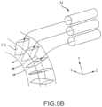
- FIG. 9B a perspective view of outlet ducts 514 in fluidic communication with a plurality of hollow struts including hollow strut 910 is illustrated, in accordance with various embodiments.
- a plurality of hollow struts may be arranged about an engine axis.
- Each outlet duct included in plurality of outlet ducts 514 may be in fluidic communication with a separate hollow strut 910.
- outlet ducts 514 may be in fluidic communication with one or more hollow struts.
- references to "various embodiments”, “one embodiment”, “an embodiment”, “an example embodiment”, etc. indicate that the embodiment described may include a particular feature, structure, or characteristic, but every embodiment may not necessarily include the particular feature, structure, or characteristic. Moreover, such phrases are not necessarily referring to the same embodiment. Further, when a particular feature, structure, or characteristic is described in connection with an embodiment, it is submitted that it is within the knowledge of one skilled in the art to affect such feature, structure, or characteristic in connection with other embodiments whether or not explicitly described. After reading the description, it will be apparent to one skilled in the relevant art(s) how to implement the disclosure in alternative embodiments.
Landscapes
- Engineering & Computer Science (AREA)
- Mechanical Engineering (AREA)
- General Engineering & Computer Science (AREA)
- Chemical & Material Sciences (AREA)
- Combustion & Propulsion (AREA)
- Physics & Mathematics (AREA)
- Thermal Sciences (AREA)
- Heat-Exchange Devices With Radiators And Conduit Assemblies (AREA)
- Structures Of Non-Positive Displacement Pumps (AREA)
Description
- The present disclosure relates to gas turbine engines, and, more specifically, to heat exchangers (HEX) for cooling air of gas turbine engines.
- As higher pressures are achieved in compressors of gas turbine engines, the temperature of compressed air in and/or leaving the compressors may increase as well. As a result, various components in a gas turbine engine may experience thermal stress. Thus, a heat exchanger (HEX) may be provided to cool hot air in a gas turbine engine. A heat exchanger may experience various loads between mounting systems and pipes for routing air.
- A prior art heat exchanger arrangement for a gas turbine engine having the features of the preamble to claim 1 is disclosed in
US 3,968,834 . A similar prior art heat exchanger arrangement for a gas turbine engine is also disclosed inUS 5,243,815 . - The present invention provides a heat exchanger arrangement for a gas turbine engine according to claim 1.
- Features of embodiments are recited in the dependent claims. These features and elements as well as the operation of the disclosed embodiments will become more apparent in light of the following description and accompanying drawings.
- The subject matter of the present disclosure is particularly pointed out and distinctly claimed in the concluding portion of the specification. A more complete understanding of the present disclosure, however, may best be obtained by referring to the detailed description and claims when considered in connection with the figures, wherein like numerals denote like elements.
-
FIG. 1 illustrates a cross-sectional view of an exemplary gas turbine engine, in accordance with various embodiments; -
FIG. 2 illustrates a cross-sectional view of an exemplary gas turbine engine, in accordance with various embodiments; -
FIG. 3 illustrates the primary-flow gas path in a gas turbine engine through the low pressure compressor, high-pressure compressor, combustor, high-pressure turbine, and low-pressure turbine, in accordance with various embodiments; -
FIG. 4 illustrates a cross-sectional view of a heat exchanger, in accordance with various embodiments; -
FIG. 5 illustrates a perspective view of a heat exchanger installed on a gas turbine engine, in accordance with various embodiments; -
FIG. 6A illustrates a front view of a heat exchanger, in accordance with various embodiments; -
FIG. 6B illustrates an aft view of a heat exchanger, in accordance with various embodiments; -
FIG. 7 illustrates an xyz-axis illustrating six degrees of freedom, in accordance with various embodiments; -
FIG. 8 illustrates a heat exchanger arrangement coupled to a gas turbine engine, in accordance with various embodiments; -
FIG. 9A illustrates a cross-sectional view of an exemplary gas turbine engine having a hollow strut, in accordance with various embodiments; and -
FIG. 9B illustrates a perspective view of heat exchanger outlet ducts in fluidic communication with a plurality of hollow struts, in accordance with various embodiments. - The detailed description of exemplary embodiments herein makes reference to the accompanying drawings, which show exemplary embodiments by way of illustration. While these exemplary embodiments are described in sufficient detail to enable those skilled in the art to practice the inventions, it should be understood that other embodiments may be realized and that logical changes and adaptations in design and construction may be made in accordance with this invention and the teachings herein. Thus, the detailed description herein is presented for purposes of illustration only and not of limitation. The scope of the invention is defined by the appended claims. For example, the steps recited in any of the method or process descriptions may be executed in any order and are not necessarily limited to the order presented. Furthermore, any reference to singular includes plural embodiments, and any reference to more than one component or step may include a singular embodiment or step. Also, any reference to attached, fixed, connected or the like may include permanent, removable, temporary, partial, full and/or any other possible attachment option. Additionally, any reference to without contact (or similar phrases) may also include reduced contact or minimal contact. Surface shading lines may be used throughout the figures to denote different parts but not necessarily to denote the same or different materials. In some cases, reference coordinates may be specific to each figure.
- As used herein, "aft" refers to the direction associated with the tail (e.g., the back end) of an aircraft, or generally, to the direction of exhaust of the gas turbine. As used herein, "forward" refers to the direction associated with the nose (e.g., the front end) of an aircraft, or generally, to the direction of flight or motion. As used herein, "gas" and "air" may be used interchangeably.
- Fuel efficiency of gas turbine engines is known to be proportional to the ratio of the exit pressure and the inlet pressure of the engine, or overall pressure ratio (OPR). As the OPR increases, the efficiency of the engine generally increases. However, a byproduct of OPR is high operating temperatures in various portions of the engine, such as the high pressure compressor for example. Materials used in gas turbine engines have temperature thresholds which cannot be surpassed for successful operation. Cooling air may be used to decrease operating temperatures of various components in a gas turbine engine. Generally, air from a compressor section of a gas turbine engine is used to cool other sections of the engine. However, as the OPR of gas turbine engines increases, the air from the compressor section may become increasingly hot. A heat exchanger (HEX) may be used to cool the air from a compressor section, thus providing cooled cooling air.
- A heat exchanger for a gas turbine engine may be coupled to an engine case via a mounting system comprising links and via pipes or ducts for routing air for cooling. The mounting system may comprise a statically determined mounting system. The pipes may comprise a stiffness. The pipes may include bends in the pipes which may decrease their stiffness. The links may comprise a stiffness. The links may each comprise single vector load carriers. The stiffness ratio, or the spring rate ratio between the pipes and the links may be between one percent and thirty percent.
- With reference to
FIG. 1 , a schematic view of a gas turbine engine is illustrated, in accordance with various embodiments.Gas turbine engine 110 may includecore engine 120. Core air flow C flows throughcore engine 120 and is expelled throughexhaust outlet 118 surroundingtail cone 122. -
Core engine 120 drives afan 114 arranged in a bypass flow path B. Air in bypass flow-path B flows in the aft direction (z-direction) along bypass flow-path B. At least a portion of bypass flow path B may be defined bynacelle 112 and inner fixed structure (IPS) 126.Fan case 132 may surroundfan 114.Fan case 132 may be housed withinfan nacelle 112. - With momentary additional reference to
FIG. 2 ,nacelle 112 typically comprises two halves which are typically mounted topylon 270.Fan case structure 233 may provide structure for securinggas turbine engine 110 to a pylon 160. According to various embodiments,multiple guide vanes 116 may extend radially betweencore engine 120 and intermediate case IMC 134. -
Upper bifurcation 144 andlower bifurcation 142 may extend radially between thenacelle 112 andIFS 126 in locations opposite one another to accommodate engine components such as wires and fluids, for example. - Inner
fixed structure 126 surroundscore engine 120 and provides core compartments 128. Various components may be provided incore compartment 128 such as fluid conduits and/or acompressed air duct 130, for example.Compressed air duct 130 may be under high pressure and may supply compressed cooling air from a compressor stage to a high pressure turbine stage, for example. In various embodiments, a heat exchanger may be coupled tocompressed air duct 130. - With respect to
FIG. 2 , elements with like element numbering as depicted inFIG. 1 are intended to be the same and will not necessarily be repeated for the sake of clarity. - In various embodiments and with reference to
FIG. 2 , agas turbine engine 110 is provided.Gas turbine engine 110 may be a two-spool turbofan that generally incorporates afan section 222, acompressor section 224, acombustor section 226 and aturbine section 228. Alternative engines may include, for example, an augmentor section among other systems or features. In operation,fan section 222 can drive air along a bypass flow-path B whilecompressor section 224 can drive air along a core flow-path C for compression and communication intocombustor section 226 then expansion throughturbine section 228. Although depicted as a turbofangas turbine engine 110 herein, it should be understood that the concepts described herein are not limited to use with two-spool turbofans as the teachings may be applied to other types of turbine engines including three-spool architectures. -
Gas turbine engine 110 may generally comprise alow speed spool 230 and ahigh speed spool 232 mounted for rotation about an engine central longitudinal axis A-A' relative to an enginestatic structure 236 via one or more bearing systems 238 (shown as bearing system 238-1 and bearing system 238-2 inFIG. 2 ). It should be understood that various bearingsystems 238 at various locations may alternatively or additionally be provided including, for example,bearing system 238, bearing system 238-1, and bearing system 238-2. -
Low speed spool 230 may generally comprise aninner shaft 240 that interconnects afan 114, a low pressure (or first)compressor section 244 and a low pressure (or first)turbine section 246.Inner shaft 240 may be connected to fan 114 through a gearedarchitecture 248 that can drivefan 114 at a lower speed thanlow speed spool 230.Geared architecture 248 may comprise agear assembly 260 enclosed within agear housing 262.Gear assembly 260 couplesinner shaft 240 to a rotating fan structure.High speed spool 232 may comprise anouter shaft 250 that interconnects a high-pressure compressor ("HPC") 252 (e.g., a second compressor section) and high pressure (or second)turbine section 254. Acombustor 256 may be located betweenHPC 252 andhigh pressure turbine 254. Amid-turbine frame 257 of enginestatic structure 236 may be located generally betweenhigh pressure turbine 254 andlow pressure turbine 246.Mid-turbine frame 257 may support one ormore bearing systems 238 inturbine section 228.Inner shaft 240 andouter shaft 250 may be concentric and rotate via bearing systems 23 8 about the engine central longitudinal axis A-A', which is collinear with their longitudinal axes. As used herein, a "high pressure" compressor or turbine experiences a higher pressure than a corresponding "low pressure" compressor or turbine. - The core airflow C may be compressed by
low pressure compressor 244 thenHPC 252, mixed and burned with fuel incombustor 256, then expanded overhigh pressure turbine 254 andlow pressure turbine 246.Mid-turbine frame 257 includesairfoils 259 which are in the core airflow path.Low pressure turbine 246 andhigh pressure turbine 254 rotationally drive the respectivelow speed spool 230 andhigh speed spool 232 in response to the expansion. -
Gas turbine engine 110 may be, for example, a high-bypass geared aircraft engine. In various embodiments, the bypass ratio ofgas turbine engine 110 may be greater than about six (6). In various embodiments, the bypass ratio ofgas turbine engine 110 may be greater than ten (10). In various embodiments, gearedarchitecture 248 may be an epicyclic gear train, such as a star gear system (sun gear in meshing engagement with a plurality of star gears supported by a carrier and in meshing engagement with a ring gear) or other gear system.Geared architecture 248 may have a gear reduction ratio of greater than about 2.3 andlow pressure turbine 246 may have a pressure ratio that is greater than about 5. In various embodiments, the bypass ratio ofgas turbine engine 110 is greater than about ten (10:1). In various embodiments, the diameter offan 114 may be significantly larger than that of thelow pressure compressor 244, and thelow pressure turbine 246 may have a pressure ratio that is greater than about 5:1.Low pressure turbine 246 pressure ratio may be measured prior to inlet oflow pressure turbine 246 as related to the pressure at the outlet oflow pressure turbine 246 prior to an exhaust nozzle. It should be understood, however, that the above parameters are exemplary of various embodiments of a suitable geared architecture engine and that the present disclosure contemplates other gas turbine engines including direct drive turbofans.FIG. 1 andFIG. 2 provide a general understanding of the sections in a gas turbine engine, and are not intended to limit the disclosure. The present disclosure may extend to all types of turbine engines, including turbofan gas turbine engines and turbojet engines, for all types of applications. - With respect to
FIG. 3 , elements with like element numbering as depicted inFIG. 1 andFIG. 2 are intended to be the same and will not necessarily be repeated for the sake of clarity. -
FIG. 3 illustrates the primary flow gas path throughcore engine 120, in accordance with various embodiments.Core engine 120 may include enginestatic structure 236, low-pressure compressor 244, high-pressure compressor 252,combustor 256, high-pressure turbine 254, and low-pressure turbine C. Enginestatic structure 236 may be referred to as an engine case. Gas may flow into low-pressure compressor 244 along gas path C. Gas flowing through low-pressure compressor 244 along gas path C may be compressed, resulting in an increase in pressure and temperature relative to the pressure and temperature upon entering low-pressure compressor 244. Gas may flow into high-pressure compressor 252 along gas path C. Gas flowing through high-pressure compressor 252 along gas path C may be compressed, resulting in an increase in pressure and temperature relative to the pressure and temperature upon entering high-pressure compressor 252. Uncombusted gas in gas path C leaving high-pressure compressor 252 may be referred to as T3 gas. T3 gas may have a varying temperature at different engine speeds. The temperature of T3 gas may be about 400°F (205°C) whencore engine 120 is at idle speeds and may reach about 1,400°F (760°C) or higher ascore engine 120 accelerates for takeoff, where the term "about" in this context only may refer to +/- 200°F (111°C). Different engines may have higher temperatures or lower temperatures at each stage. T3 gas may be present atlocation 314 ofcore engine 120. T3 gas leaving the high-pressure compressor 252 may then flow intocombustor 256 to supplycombustor 256 with air for combustion. - In various embodiments, uncombusted T3 gas may be mixed with fuel and burned in
combustor 256. Combusted gas incombustor 256 may be referred to as T4 gas. T4 gas may leavecombustor 256 and enter high-pressure turbine 254. T4 gas may reach or exceed temperatures of up to 3,500°F (1,925°C) or higher. T4 gas may be located atlocation 316, for example. T4 gas leaving combustor may follow gas path C to drive high-pressure turbine 254. - In various embodiments, combusted gas that has entered, but not exited, high-
pressure turbine 254 may be identified as T4.25 gas. T4.25 gas may be significantly cooler than T4gas exiting combustor 256. For example, under operating conditions such as during flight, T4.25 gas may be at temperatures of about 1,000°F-2,000°F (537°C-1,093°C), where the term "about" in this context only may refer to +/- 500°F (278°C). T4.25 gas may be located atlocation 318, for example. The T4.25 gas then follows out high-pressure turbine 254 and into low-pressure turbine 246 along gas path C. - In various embodiments, combusted gas exiting high-
pressure turbine 254 and entering low-pressure turbine 246 may be referred to as T4.5 gas. T4.5 gas may be cooler than T4.25 gas found in the high-pressure compressor or T4 gas exiting the combustor. For example, T4.5 gas may be about 1,500°F (815°C) degrees at idle, where the term "about" in this context only may refer to +/- 500°F (278°C). T4.5 gas may be located atlocation 320 in gas path C, for example. The T4.5 gas then follows gas path C into low-pressure turbine 246. - With reference to
FIG. 4 , a cross-sectional view of a heat exchanger (HEX) 400 is illustrated. An x-y-z axis is provided for ease of illustration. In various embodiments,HEX 400 may comprise acentral manifold 410 and a plurality oftubes 430. In various embodiments,central manifold 410 may comprise aninlet portion 412, afirst outlet portion 414, and asecond outlet portion 416. In various embodiments,first outlet portion 414 may be located on the opposite side ofinlet portion 412 assecond outlet portion 416. In various embodiments,first outlet portion 414 may be located adjacent to inlet portion 412 (in the positive y-direction). In various embodiments,second outlet portion 416 may be located adjacent to inlet portion 412 (in the negative y-direction). In various embodiments,inlet portion 412,first outlet portion 414, andsecond outlet portion 416 may each individually define a cylindrical void. In various embodiments,HEX 400 may further comprise ashroud 450. In various embodiments,shroud 450 may be coupled tocentral manifold 410.Shroud 450 may at least partially encasecentral manifold 410 andtubes 430. - In various embodiments, a plurality of baffles, such as
baffle 436 for example, may be coupled to plurality oftubes 430.Baffle 436 may comprise a plurality of apertures into which plurality oftubes 430 are inserted.Baffle 436 may add to the stiffness of plurality oftubes 430. In various embodiments, with momentary reference toFIG. 1 , the number of baffles installed over plurality oftubes 430 may be determined by the highest operating frequency ofgas turbine engine 110. For example, baffles, such asbaffle 436 may be installed over plurality oftubes 430 until the natural frequency of plurality oftubes 430 is higher than the highest operating frequency ofgas turbine engine 110. In various embodiments, abaffle support 438 may be coupled to baffle 436. - With reference now to
FIG. 3 andFIG. 4 , in various embodiments,central manifold 410 and/or plurality oftubes 430 may be made of a high performance nickel-chromium alloy such as an austenitic nickel-chromium-based superalloy (e.g., INCONEL or HAYNES 282), metals, ceramics, or other materials suitable to withstand T3 gas temperatures that may exceed 1,100°F (593°C) degrees whencore engine 120 is operating at takeoff speeds. - With reference to
FIG. 4 ,inlet portion 412 may include afirst attachment feature 442 and asecond attachment feature 444. In various embodiments,first attachment feature 442 may define a hemispherical void. In various embodiments,second attachment feature 444 may define a hemispherical void. In various embodiments,first attachment feature 442 may be detachably coupled toinlet portion 412. In various embodiments,first attachment feature 442 may be permanently coupled toinlet portion 412. For example,first attachment feature 442 may be welded, soldered, brazed, or otherwise suitably coupled toinlet portion 412. In various embodiments,second attachment feature 444 may be detachably coupled toinlet portion 412. In various embodiments,second attachment feature 444 may be permanently coupled toinlet portion 412. For example,second attachment feature 444 may be welded, soldered, brazed, or otherwise suitably coupled toinlet portion 412. - In various embodiments, air may enter
HEX 400 viainlet pipe 404. In various embodiments,HEX 400 may be coupled viainlet pipe 404 to a high pressure compressor such as high-pressure compressor 252 ofFIG. 2 andFIG. 3 . Accordingly,HEX 400 may be in fluid communication viainlet portion 412 with acompressor section 224 of a gas turbine engine. In various embodiments,HEX 400 may be coupled viainlet pipe 404 to a compressor section, combustor section, and/or a turbine section of a gas turbine engine. In various embodiments,HEX 400 may be coupled to any portion of a gas turbine engine. - In various embodiments,
HEX 400 may comprise hot air flow path E. Hot air flow path E may be defined byinlet portion 412, plurality oftubes 430,first outlet portion 414, and/orsecond outlet portion 416. Upon enteringinlet portion 412 viainlet pipe 404, air may follow hot air flow path E and enter the plurality oftubes 430 frominlet portion 412 and then exit the plurality oftubes 430 into one offirst outlet portion 414 and/orsecond outlet portion 416. For example, air may enterinlet portion 412, then entertube 432, next it may exittube 432 intofirst outlet portion 414, and finally exitfirst outlet portion 414 viafirst outlet pipe 406. In a further example, air may enterinlet portion 412, then entertube 434, next it may exittube 434 intosecond outlet portion 416, and finally exitsecond outlet portion 416 viasecond outlet pipe 408. Air exiting eitherfirst outlet portion 414 orsecond outlet portion 416 may be used to cool various portions of a gas turbine engine. In this regard, air flowing through air flow path E may enterHEX 400 via hot-side inlet duct 512 as described inFIG. 5 and may exitHEX 400 via hot-side outlet ducts 514, also as described inFIG. 5 . In various embodiments, while in plurality oftubes 430, air in hot air flow path E may transfer heat to air in cooling air flow path F. - In various embodiments,
inner surface 454 ofshroud 450 may at least partially define a cooling air flow pathF. Outer surface 418 ofcentral manifold 410 may at least partially define cooling air flow path F. The outer surface of the plurality oftubes 430 may at least partially define cooling air flow path F. In various embodiments, air from bypass flow path B ofFIG. 1 may enter cooling air flow path F. In various embodiments, air in cooling air flow path F may flow generally in an aft direction (positive z-direction). In this regard, air flowing through air flow path F may enterHEX 400 via cold-side inlet 508 as described inFIG. 5 and may exitHEX 400 via cold-side outlet 510, also as described inFIG. 5 . In various embodiments, heat from air in the plurality oftubes 430 may be transferred to air in cooling air flow path F. In various embodiments, the transfer of heat may occur in a convective manner. Accordingly, the temperature of air ininlet portion 412 may be greater than the temperature of air infirst outlet portion 414 andsecond outlet portion 416. In various embodiments, the flow of air in plurality oftubes 430 may be orthogonal to the flow of air in cooling air flow path F. Thus, the flow of air intubes 430 and the flow of air in cooling air flow path F may comprise a cross-flow. Accordingly, plurality oftubes 430 may extend in a direction which is orthogonal to cooling air flow path F. - In various embodiments, a pressure gradient may exist between air in hot air flow path E and cooling air flow path F. In various embodiments, as previously mentioned,
inlet portion 412,first outlet portion 414, andsecond outlet portion 416 may each individually define a cylindrical void as shown inFIG. 4 . In various embodiments, air pressure ininlet portion 412 may reach up to 500 pounds per square inch absolute (500 psia) (3,447,378.6 Pascal) or more, while air pressure in cooling air flow path F may generally vary between 14.7 psia (101,352.9 Pascal) and 21 psia (144,789.9 Pascal). In various embodiments, the cylindrical geometry ofinlet portion 412,first outlet portion 414, andsecond outlet portion 416 may be ideal to handle the amount of pressure experienced by these portions. In various embodiments, air entering hot air flow path E may reach temperatures of about 1,400°F (760°C) or higher. In various embodiments, with reference toFIG. 3 , air entering hot air flow path E may comprise T3 gas. In various embodiments, air entering cooling air flow path F may reach temperatures of about 100°F (38°C) or higher. In various embodiments, air entering cooling air flow path F may comprise engine bypass air. In various embodiments, engine bypass air may comprise air from bypass flow path B ofFIG. 1 . - With reference to
FIG. 5 , aheat exchanger arrangement 500 installed on anengine case 540 is illustrated, in accordance with the claims. In various embodiments, heat exchanger (HEX) 502 is similar toHEX 400 as illustrated inFIG. 4 . In accordance with the claims,heat exchanger arrangement 500 includesheat exchanger 502, plurality ofpipes 506, cold-side inlet 508, cold-side outlet 510, and mountingsystem 501.Heat exchanger 502 includesfirst attachment feature 526 andsecond attachment feature 528.Heat exchanger 502 further includesthird attachment feature 530 and fourth attachment feature 532 (not shown inFIG. 5 , seeFIG. 6A andFIG. 6B ).Core engine 120 includesengine case 540.Engine case 540 includesdiffuser case 542 andturbine case 546. As described inFIG. 4 , fan bypass air is conducted through cold-side inlet 508 and cold-side outlet 510. -
HEX 502 may be located directly radially outward fromdiffuser case 542.HEX 502 may be located directly radially outward fromturbine case 546.HEX 502 may be located axially in line (i.e., in line with respect to the y-direction) withdiffuser case 542.HEX 502 may be located axially in line withturbine case 546.HEX 502 may be located axially in line with combustor 256 (seeFIG. 2 ). - Plurality of ducts (also referred to herein as plurality of pipes) 506 include inlet (also referred to herein as hot-side inlet duct) 512. Plurality of
pipes 506 include plurality of outlet ducts (also referred to herein as plurality of hot-side outlet ducts) 514. Plurality ofoutlet ducts 514 include first outlet duct (also referred to herein as hot-side outlet duct) 516 and second outlet duct (also referred to herein as hot-side outlet duct) 518. Plurality ofoutlet ducts 514 may be coupled todiffuser case 542. Plurality ofoutlet ducts 514 may be directly coupled todiffuser case 542 as illustrated inFIG. 5 . Plurality ofoutlet ducts 514 may be in fluid communication with compressor section 224 (seeFIG. 2 ). - In accordance with the claims, mounting
system 501 comprises a plurality of links (also referred to herein as a plurality of supporting links) includingfirst link 520,second link 522,third link 524,second attachment feature 528,third attachment feature 530, and fourth attachment feature 532 (seeFIG. 6A ). Mountingsystem 501 is for securingheat exchanger 502 tocore engine 120. In the depicted embodiment, heat exchanger is coupled to first link,second link 522, andthird link 524 viafirst attachment feature 526. First link 520 is coupled betweenfirst attachment feature 526 anddiffuser case 542.Second link 522 is coupled betweenfirst attachment feature 526 anddiffuser case 542.Third link 524 is coupled betweenfirst attachment feature 526 anddiffuser case 542. - With reference to
FIGs. 6A-6B , like element numbering, as depicted inFIG. 5 , are intended to be the same and will not necessarily be repeated for the sake of clarity. - With reference to
FIG. 6A , a front view ofheat exchanger 502 is illustrated, in accordance with various embodiments. First link 520 extends substantially in an axial direction (i.e., z-direction).First end 620 offirst link 520 is coupled to diffuser case 542 (seeFIG. 5 ).Second end 622 offirst link 520 is coupled tofirst attachment feature 526.First end 620 offirst link 520 is substantially prevented from moving in a radial direction (i.e., y-direction), with respect to thediffuser case 542.First end 620 offirst link 520 is substantially prevented from moving in an axial direction (i.e., z-direction), with respect to thediffuser case 542. Thus,first end 620 offirst link 520 is substantially prevented from moving in the y-z plane, with respect to thediffuser case 542. However,first end 620 offirst link 520 is free to move in all other linear and rotational directions. In this manner,first attachment feature 526 is substantially prevented from moving in the axial direction and in the radial direction, with respect to diffuser case 542 (seeFIG. 5 ). - In the depicted embodiment,
second link 522 extends in a circumferential direction (i.e., in the x-y plane).First end 624 ofsecond link 522 is coupled to diffuser case 542 (seeFIG. 5 ).Second end 626 ofsecond link 522 is coupled tofirst attachment feature 526.First end 624 ofsecond link 522 is substantially prevented from moving in a radial direction (i.e., y-direction), with respect todiffuser case 542.First end 624 ofsecond link 522 is substantially prevented from moving in a circumferential direction (i.e., x-direction), with respect to thediffuser case 542. Thus,first end 624 ofsecond link 522 is substantially prevented from moving in the x-y plane, with respect to thediffuser case 542. However,first end 624 ofsecond link 522 is free to move in all other linear and rotational directions. - Similarly, in the depicted embodiments,
third link 524 extends in a circumferential direction (i.e., in the x-y plane).First end 628 ofthird link 524 is coupled to diffuser case 542 (seeFIG. 5 ).Second end 630 ofthird link 524 is coupled tofirst attachment feature 526.First end 628 ofthird link 524 is substantially prevented from moving in a radial direction (i.e., y-direction), with respect todiffuser case 542.First end 628 ofthird link 524 is substantially prevented from moving in a circumferential direction (i.e., x-direction), with respect to thediffuser case 542. Thus,first end 628 ofthird link 524 is substantially prevented from moving in the x-y plane, with respect to thediffuser case 542. However,first end 628 ofthird link 524 is free to move in all other linear and rotational directions. In this manner,first attachment feature 526 is substantially prevented from moving in the radial direction and in the circumferential direction, with respect to diffuser case 542 (seeFIG. 5 ). - In the depicted embodiment,
first link 520 is coupled to core engine 120 (seeFIG. 5 ) via a mounting bracket (also referred to herein as a first mounting bracket) 632. Mountingbracket 632 is coupled directly to engine case 540 (seeFIG. 5 ). Mountingbracket 632 is coupled directly todiffuser case 542 or turbine case 546 (seeFIG. 5 ). Similarly,second link 522 is coupled to core engine 120 (seeFIG. 5 ) via a mounting bracket (also referred to herein as a second mounting bracket) 634. Mountingbracket 634 is coupled directly to engine case 540 (seeFIG. 5 ). Mountingbracket 634 is coupled directly todiffuser case 542 or turbine case 546 (seeFIG. 5 ). Similarly,third link 524 is coupled to core engine 120 (seeFIG. 5 ) via a mounting bracket (also referred to herein as a third mounting bracket) 636. Mountingbracket 636 is coupled directly to engine case 540 (seeFIG. 5 ). Mountingbracket 636 is coupled directly todiffuser case 542 or turbine case 546 (seeFIG. 5 ). - With reference to
FIG. 6B , an aft view ofheat exchanger 502 is illustrated, in accordance with various embodiments.Second attachment feature 528 is coupled to core engine 120 (seeFIG. 5 ).Second attachment feature 528 is substantially prevented from moving in a circumferential direction (i.e., x-direction) with respect to diffuser case 542 (seeFIG. 5 ).Second attachment feature 528 is coupled to core engine 120 (seeFIG. 5 ) via a mounting bracket (also referred to herein as a fourth mounting bracket) 646. Mountingbracket 646 is coupled directly to engine case 540 (seeFIG. 5 ). Mountingbracket 646 is coupled directly todiffuser case 542 or turbine case 546 (seeFIG. 5 ). - In the depicted embodiment,
third attachment feature 530 is coupled to core engine 120 (seeFIG. 5 ).Third attachment feature 530 is coupled to core engine 120 (seeFIG. 5 ) via a mounting bracket (also referred to herein as a fifth mounting bracket) 648. In the depicted embodiment, mountingbracket 648 is coupled to engine case 540 (seeFIG. 5 ). Mountingbracket 648 is coupled directly todiffuser case 542 and/or turbine case 546 (seeFIG. 5 ).Third attachment feature 530 is substantially prevented from moving in a radial direction (i.e., y-direction). - Similarly,
fourth attachment feature 532 is coupled to core engine 120 (seeFIG. 5 ).Fourth attachment feature 532 is coupled to core engine 120 (seeFIG. 5 ) via a mounting bracket (also referred to herein as a sixth mounting bracket) 649. In the depicted embodiment, mountingbracket 649 is coupled to engine case 540 (seeFIG. 5 ). Mountingbracket 649 is coupled directly todiffuser case 542 and/or turbine case 546 (seeFIG. 5 ).Fourth attachment feature 532 is substantially prevented from moving in a radial direction (i.e., y-direction). - In accordance with the claims,
inlet 512 comprises a plurality of inlet pipes includingfirst inlet pipe 640 andsecond inlet pipe 642. - With reference to
FIG. 7 , an illustration of six degrees of freedom is provided, in accordance with the claims. In accordance with the claims, the heat exchanger arrangement and the mounting system, as disclosed herein, comprises a statically determined six degrees of freedom system. Xyz-axis 700 is provided for illustration purposes. For example, a system is capable of moving in 6 directions; three linear direction and three rotational directions. Thus, a system is capable of moving in the x-direction, the y-direction, the z-direction, therotational direction 702 about the x-axis, therotational direction 704 about the y-axis, and therotational direction 706 about the z-axis. Such a system is fixed in a manner as to provide a means of limiting the movement of said system. As disclosed herein, six mounting points for a heat exchanger are provided to prevent movement of said heat exchanger in each of the six degrees of freedom. Stated another way, a heat exchanger is provided having a mounting system which is statically determined in each of the six degrees of freedom. - With reference to
FIG. 6A andFIG. 6B ,HEX 502 is statically determined in the x-direction viafirst attachment feature 526 andsecond link 522 andthird link 524.HEX 502 is statically determined in the y-direction viathird attachment feature 530 andfourth attachment feature 532.HEX 502 is statically determined in the z-direction viafirst attachment feature 526 andfirst link 520.HEX 502 is statically determined in the rotational direction about the x-axis viafirst attachment feature 526 andsecond attachment feature 528.HEX 502 is statically determined in the rotational direction about the y-axis viafirst attachment feature 526 andsecond attachment feature 528.HEX 502 is statically determined in the rotational direction about the z-axis viathird attachment feature 530 andfourth attachment feature 532. In this manner, mounting system 501 (seeFIG. 5 ) is a statically determined six degrees of freedom system. - An over-determined system is a system having more than one means of limiting a systems movement in a single direction. The heat exchanger arrangement as disclosed herein is arranged as to prevent an over-determined system to allow for thermal growth during operation.
- With reference to
FIG. 5 ,first link 520 may comprise a single vector load path. Stated another way,first link 520 may be configured to transfer loads betweenheat exchanger 502 andengine case 520 only under compression or tension. - In various embodiments, plurality of
pipes 506 may contain pressurized air. Said pressurized air may cause a load on plurality ofpipes 506. Said load may be conducted betweenHEX 502 andengine case 540 via plurality ofpipes 506 and via mountingsystem 501. - With reference to
FIG. 8 , aheat exchanger arrangement 800 is provided, in accordance with various embodiments.Heat exchanger arrangement 800 is similar to heat exchanger arrangement 500 (seeFIG. 5 ).Heat exchanger arrangement 800 includes heat exchanger (HEX) 802, plurality oflinks 804 and plurality of pipes 806.Heat exchanger 802 is coupled tocore engine 120 via plurality oflinks 804 and plurality of pipes 806. Afirst load 805 may be transferred betweenHEX 802 andcore engine 120 via plurality oflinks 804. Asecond load 807 may be transferred betweenHEX 802 andcore engine 120 via plurality of pipes 806. The magnitude of thefirst load 805 and the magnitude of thesecond load 807 may be determined by the stiffness of plurality oflinks 804 and by the stiffness of plurality of pipes 806. For example, the stiffness of plurality of pipes 806 may be decreased which may decrease the magnitude ofsecond load 807. Stated another way, the stiffness of plurality oflinks 804 may be increased, which may increase the magnitude offirst load 805. Thus, the relative magnitudes offirst load 805 andsecond load 807 may be varied depending on the stiffness of the plurality oflinks 804 and the plurality of pipes 806. Similarly, the format in which the plurality oflinks 804 is arranged may effectively vary their stiffness. The pipe-to-linkage spring rate ratio may be the ratio of the effective stiffness of the plurality of pipes 806 and the effective stiffness of the plurality oflinks 804. Thus, a spring rate ratio (also referred to herein as a pipe-to-linkage spring rate ratio) may exist between plurality oflinks 804 and plurality of pipes 806. The pipe-to-linkage spring rate ratio may be the ratio of the total load conducted via the plurality of pipes 806 (LP) and the total load conducted via the plurality of links 804 (LL). For example, if one tenth of the total load betweenHEX 802 andengine case 540 was conducted via the plurality of pipes 806, then nine tenths of the load betweenHEX 802 andengine case 540 would be conducted via the plurality of links, and the pipe-to-linkage spring rate ratio may be one ninth. Stated another way, if ten pounds of force betweenHEX 802 andengine case 540 was conducted via the plurality of pipes 806, and ninety pounds of force betweenHEX 802 andengine case 540 was conducted via the plurality of links, then the pipe-to-linkage spring rate ratio may be ten divided by ninety or one ninth or 11.11%. Stated another way, the pipe-to-linkage spring rate ratio (SRRPL) may be determined by equation 1:
- In various embodiments, the spring rate ratio between the plurality of pipes 806 and the plurality of links may be between 1% and 30%. In various embodiments, the spring rate ratio between the plurality of pipes 806 and the plurality of links may be between 5% and 20%. In various embodiments, the spring rate ratio between the plurality of pipes 806 and the plurality of links may be between 5% and 15%. In various embodiments, the spring rate ratio between the plurality of pipes 806 and the plurality of links may be about 10%, wherein the term "about", in this context only, only means ± 3%.
- With reference to
FIG. 9A , a cross section view of agas turbine engine 120 is illustrated, in accordance with various embodiments. In various embodiments,outlet ducts 514 may be in fluidic communication withhollow strut 910.Hollow strut 910 may extend within plenum (also referred to herein as diffuser case plenum) 912. Cooled air may be conducted throughoutlet ducts 514 and intohollow strut 910.Hollow strut 910 may extend betweenengine case 540 and engine axis A-A' (seeFIG. 2 ).Inlet 512 may be directly coupled toengine case 540.Inlet 512 may receive air fromplenum 912. - With reference to
FIG. 9B , a perspective view ofoutlet ducts 514 in fluidic communication with a plurality of hollow struts includinghollow strut 910 is illustrated, in accordance with various embodiments. As illustrated inFIG. 9B , a plurality of hollow struts may be arranged about an engine axis. Each outlet duct included in plurality ofoutlet ducts 514 may be in fluidic communication with a separatehollow strut 910. However, in various embodiments,outlet ducts 514 may be in fluidic communication with one or more hollow struts. - Benefits, other advantages, and solutions to problems have been described herein with regard to specific embodiments. Furthermore, the connecting lines shown in the various figures contained herein are intended to represent exemplary functional relationships and/or physical couplings between the various elements. It should be noted that many alternative or additional functional relationships or physical connections may be present in a practical system. However, the benefits, advantages, solutions to problems, and any elements that may cause any benefit, advantage, or solution to occur or become more pronounced are not to be construed as critical, required, or essential features or elements of the inventions. The scope of the inventions is accordingly to be limited by nothing other than the appended claims, in which reference to an element in the singular is not intended to mean "one and only one" unless explicitly so stated, but rather "one or more." Moreover, where a phrase similar to "at least one of A, B, or C" is used in the claims, it is intended that the phrase be interpreted to mean that A alone may be present in an embodiment, B alone may be present in an embodiment, C alone may be present in an embodiment, or that any combination of the elements A, B and C may be present in a single embodiment; for example, A and B, A and C, B and C, or A and B and C.
- Systems, methods and apparatus are provided herein. In the detailed description herein, references to "various embodiments", "one embodiment", "an embodiment", "an example embodiment", etc., indicate that the embodiment described may include a particular feature, structure, or characteristic, but every embodiment may not necessarily include the particular feature, structure, or characteristic. Moreover, such phrases are not necessarily referring to the same embodiment. Further, when a particular feature, structure, or characteristic is described in connection with an embodiment, it is submitted that it is within the knowledge of one skilled in the art to affect such feature, structure, or characteristic in connection with other embodiments whether or not explicitly described. After reading the description, it will be apparent to one skilled in the relevant art(s) how to implement the disclosure in alternative embodiments.
Claims (4)
- A heat exchanger arrangement for a gas turbine engine (110) comprising:a heat exchanger (400; 502; 802);a plurality of pipes (506) comprising,a plurality of inlet pipes comprising a hot-side inlet (512); anda plurality of outlet pipes comprising a hot-side outlet (514, 516, 518);characterized bya cold-side inlet (508);a cold-side outlet (510), the cold-side inlet (508) and the cold-side outlet (510) being for conducting a cooling air in a fan bypass flow path to transfer heat from air in the heat exchanger (400; 502; 802) to the cooling air; anda statically determined six degrees of freedom mounting system (501) comprising a plurality of links (520, 522, 524; 804) coupled to the heat exchanger (400; 502; 802) and configured to be coupled directly to a diffuser case (542), wherein the plurality of links (520, 522, 524; 804) provide six mounting points for the heat exchanger (400; 502; 802) that prevent movement of the heat exchanger (400; 502; 802) in each of the six degrees of freedom and wherein the heat exchanger arrangement prevents an over-determined system to allow for thermal growth during operation.
- The heat exchanger arrangement of claim 1, wherein the plurality of links (520, 522, 524; 804) comprise single vector load paths, wherein the plurality of links (520, 522, 524; 804) are configured to transfer loads only under at least one of compression or tension.
- The heat exchanger arrangement of claim 1 or 2, wherein a spring rate ratio between the plurality of pipes (506) and the statically determined six degrees of freedom mounting system (501) comprises between 1% and 30%, for example, between 5% and 15%.
- The heat exchanger arrangement of claim 1, 2 or 3, wherein at least a portion of the heat exchanger (400; 502; 802) is located directly radially outward from the diffuser case (542) and axially in line with the diffuser case (542).
Applications Claiming Priority (2)
| Application Number | Priority Date | Filing Date | Title |
|---|---|---|---|
| US15/074,829 US10151247B2 (en) | 2016-03-18 | 2016-03-18 | Heat exchanger suspension system with pipe-to-linkage spring rate ratio |
| EP17151865.7A EP3246544B1 (en) | 2016-03-18 | 2017-01-17 | Gas turbine engine having a heat exchanger suspension system with pipe-to-linkage spring rate ratio |
Related Parent Applications (2)
| Application Number | Title | Priority Date | Filing Date |
|---|---|---|---|
| EP17151865.7A Division EP3246544B1 (en) | 2016-03-18 | 2017-01-17 | Gas turbine engine having a heat exchanger suspension system with pipe-to-linkage spring rate ratio |
| EP17151865.7A Division-Into EP3246544B1 (en) | 2016-03-18 | 2017-01-17 | Gas turbine engine having a heat exchanger suspension system with pipe-to-linkage spring rate ratio |
Publications (3)
| Publication Number | Publication Date |
|---|---|
| EP3708809A2 EP3708809A2 (en) | 2020-09-16 |
| EP3708809A3 EP3708809A3 (en) | 2020-12-02 |
| EP3708809B1 true EP3708809B1 (en) | 2024-07-17 |
Family
ID=57881964
Family Applications (2)
| Application Number | Title | Priority Date | Filing Date |
|---|---|---|---|
| EP20165335.9A Active EP3708809B1 (en) | 2016-03-18 | 2017-01-17 | Heat exchanger suspension system |
| EP17151865.7A Active EP3246544B1 (en) | 2016-03-18 | 2017-01-17 | Gas turbine engine having a heat exchanger suspension system with pipe-to-linkage spring rate ratio |
Family Applications After (1)
| Application Number | Title | Priority Date | Filing Date |
|---|---|---|---|
| EP17151865.7A Active EP3246544B1 (en) | 2016-03-18 | 2017-01-17 | Gas turbine engine having a heat exchanger suspension system with pipe-to-linkage spring rate ratio |
Country Status (2)
| Country | Link |
|---|---|
| US (1) | US10151247B2 (en) |
| EP (2) | EP3708809B1 (en) |
Families Citing this family (6)
| Publication number | Priority date | Publication date | Assignee | Title |
|---|---|---|---|---|
| US10436115B2 (en) * | 2016-08-22 | 2019-10-08 | United Technologies Corporation | Heat exchanger for gas turbine engine with support damper mounting |
| US10317150B2 (en) * | 2016-11-21 | 2019-06-11 | United Technologies Corporation | Staged high temperature heat exchanger |
| US20190024988A1 (en) * | 2017-07-18 | 2019-01-24 | General Electric Company | Header assembly for a heat exchanger |
| US11378341B2 (en) * | 2020-01-03 | 2022-07-05 | Raytheon Technologies Corporation | Gas turbine engine heat exchanger for annular flowpaths |
| CN115267163B (en) * | 2022-06-23 | 2023-03-28 | 北京铂茵生物科技有限公司 | Chemiluminescence immunoassay kit loading, mixing and refrigerating system |
| US20250215808A1 (en) * | 2024-01-02 | 2025-07-03 | Hamilton Sundstrand Corporation | Flexible interface coupling |
Family Cites Families (48)
| Publication number | Priority date | Publication date | Assignee | Title |
|---|---|---|---|---|
| US2608054A (en) * | 1942-03-06 | 1952-08-26 | Lockheed Aircraft Corp | Air turbine starting means for gas turbine power plants |
| US3528250A (en) * | 1969-04-16 | 1970-09-15 | Gen Motors Corp | Bypass engine with afterburning and compressor bleed air heat exchanger in bypass duct |
| US3968834A (en) * | 1975-02-07 | 1976-07-13 | Caterpillar Tractor Co. | Heat exchanger mounting for a turbine engine |
| US4090358A (en) * | 1976-10-01 | 1978-05-23 | Caterpillar Tractor Co. | Heat exchanger support system |
| US4137705A (en) * | 1977-07-25 | 1979-02-06 | General Electric Company | Cooling air cooler for a gas turbine engine |
| US4556486A (en) * | 1984-02-15 | 1985-12-03 | Lesley Merket | Circulating water filtering system and method of operation |
| US4735775A (en) * | 1984-02-27 | 1988-04-05 | Baxter Travenol Laboratories, Inc. | Mass transfer device having a heat-exchanger |
| US4697633A (en) * | 1985-05-22 | 1987-10-06 | Solar Turbines Incorporated | Thermally balanced restraint system for a heat exchanger |
| DE3529457A1 (en) * | 1985-08-16 | 1987-02-26 | Mtu Muenchen Gmbh | HEAT EXCHANGER GAS TURBINE |
| US5065816A (en) * | 1990-05-29 | 1991-11-19 | Solar Turbines Incorporated | Sealing system for a circular heat exchanger |
| US5123242A (en) * | 1990-07-30 | 1992-06-23 | General Electric Company | Precooling heat exchange arrangement integral with mounting structure fairing of gas turbine engine |
| DE4118777C2 (en) * | 1991-06-07 | 2002-04-18 | Mtu Aero Engines Gmbh | Gas turbine engine with heat exchanger |
| FR2697052B1 (en) * | 1992-10-21 | 1994-12-09 | Alsthom Gec | Concrete casing of a condenser for low pressure module with independent structure. |
| FR2734320B1 (en) * | 1995-05-15 | 1997-07-18 | Aerospatiale | DEVICE FOR TAKING UP AND COOLING HOT AIR AT AN AIRCRAFT ENGINE |
| FR2734319B1 (en) * | 1995-05-15 | 1997-07-18 | Aerospatiale | DEVICE FOR TAKING UP AND COOLING HOT AIR AT AN AIRCRAFT ENGINE |
| DE19524213A1 (en) * | 1995-07-03 | 1997-01-09 | Abb Management Ag | Fuel supply for gas turbines with an annular combustion chamber |
| US5775412A (en) * | 1996-01-11 | 1998-07-07 | Gidding Engineering, Inc. | High pressure dense heat transfer area heat exchanger |
| CA2289428C (en) * | 1998-12-04 | 2008-12-09 | Beckett Gas, Inc. | Heat exchanger tube with integral restricting and turbulating structure |
| US6601392B2 (en) * | 2001-10-01 | 2003-08-05 | Ingersoll-Rand Energy Systems Corporation | Spring mounted recuperator |
| US6574950B2 (en) * | 2001-10-01 | 2003-06-10 | Ingersoll-Rand Energy Systems Corporation | Thermally responsive recuperator housing |
| DE10236380A1 (en) * | 2002-08-08 | 2004-03-04 | Mtu Aero Engines Gmbh | Recuperative exhaust gas heat exchanger for gas turbine drive has collection tube with closed end fastened radially and axially to turbine housing |
| US7094029B2 (en) * | 2003-05-06 | 2006-08-22 | General Electric Company | Methods and apparatus for controlling gas turbine engine rotor tip clearances |
| US7008183B2 (en) * | 2003-12-26 | 2006-03-07 | General Electric Company | Deflector embedded impingement baffle |
| FR2864996B1 (en) * | 2004-01-13 | 2006-03-10 | Snecma Moteurs | SYSTEM FOR COOLING HOT PARTS OF AN AIRCRAFT ENGINE, AND AIRCRAFT ENGINE EQUIPPED WITH SUCH A COOLING SYSTEM |
| US7861512B2 (en) * | 2006-08-29 | 2011-01-04 | Pratt & Whitney Canada Corp. | Turbofan bypass duct air cooled fluid cooler installation |
| US8387362B2 (en) * | 2006-10-19 | 2013-03-05 | Michael Ralph Storage | Method and apparatus for operating gas turbine engine heat exchangers |
| JP5536312B2 (en) * | 2008-04-23 | 2014-07-02 | シャープ株式会社 | Heat exchange system |
| FR2931517B1 (en) * | 2008-05-20 | 2012-09-21 | Valeo Sys Controle Moteur Sas | GAS ADMISSION DEVICE |
| WO2009158695A1 (en) * | 2008-06-27 | 2009-12-30 | Greene, Tweed Of Delaware, Inc. | Split bearing assemblies, air-cooled heat exchangers and related methods |
| US8266889B2 (en) * | 2008-08-25 | 2012-09-18 | General Electric Company | Gas turbine engine fan bleed heat exchanger system |
| JP5321271B2 (en) * | 2009-06-17 | 2013-10-23 | 株式会社デンソー | Heat exchanger for high temperature gas cooling |
| US8266888B2 (en) * | 2010-06-24 | 2012-09-18 | Pratt & Whitney Canada Corp. | Cooler in nacelle with radial coolant |
| US9458855B2 (en) * | 2010-12-30 | 2016-10-04 | Rolls-Royce North American Technologies Inc. | Compressor tip clearance control and gas turbine engine |
| US9927189B2 (en) * | 2011-07-20 | 2018-03-27 | Hamilton Sundstrand Corporation | Aircraft precooler heat exchanger |
| US8813500B2 (en) * | 2011-08-03 | 2014-08-26 | Dresser-Rand Company | Combined heat exchanger expander mounting system |
| GB201121971D0 (en) * | 2011-12-21 | 2012-02-01 | Rolls Royce Deutschland & Co Kg | Accessory mounting for a gas turbine |
| GB201200139D0 (en) * | 2012-01-06 | 2012-02-15 | Rolls Royce Plc | Coolant supply system |
| US9416677B2 (en) * | 2012-01-10 | 2016-08-16 | United Technologies Corporation | Gas turbine engine forward bearing compartment architecture |
| EP2839213B1 (en) * | 2012-01-17 | 2018-09-05 | General Electric Technology GmbH | Tube and baffle arrangement in a once-through horizontal evaporator |
| US9637241B2 (en) * | 2012-03-16 | 2017-05-02 | The Boeing Company | Engine mounting system for an aircraft |
| DE102012106782A1 (en) * | 2012-07-26 | 2014-01-30 | Halla Visteon Climate Control Corporation | Heat exchanger for exhaust gas cooling in motor vehicles |
| US9249730B2 (en) * | 2013-01-31 | 2016-02-02 | General Electric Company | Integrated inducer heat exchanger for gas turbines |
| EP2971683B1 (en) | 2013-03-14 | 2019-10-02 | United Technologies Corporation | Gas turbine engine heat exchanger manifold |
| WO2014143210A1 (en) * | 2013-03-14 | 2014-09-18 | Rolls-Royce North American Technologies, Inc. | Gas turbine engine flow duct having two rows of integrated heat exchangers |
| FR3008679B1 (en) * | 2013-07-16 | 2015-08-14 | Eurocopter France | MODULAR AND AIRCRAFT POWER PLANT WITH SUSTENTATION ROTOR |
| US11162424B2 (en) * | 2013-10-11 | 2021-11-02 | Reaction Engines Ltd | Heat exchangers |
| US9777963B2 (en) * | 2014-06-30 | 2017-10-03 | General Electric Company | Method and system for radial tubular heat exchangers |
| US10533500B2 (en) * | 2015-02-20 | 2020-01-14 | Pratt & Whitney Canada Corp. | Compound engine assembly with mount cage |
-
2016
- 2016-03-18 US US15/074,829 patent/US10151247B2/en active Active
-
2017
- 2017-01-17 EP EP20165335.9A patent/EP3708809B1/en active Active
- 2017-01-17 EP EP17151865.7A patent/EP3246544B1/en active Active
Also Published As
| Publication number | Publication date |
|---|---|
| US10151247B2 (en) | 2018-12-11 |
| EP3246544A1 (en) | 2017-11-22 |
| EP3246544B1 (en) | 2020-06-03 |
| EP3708809A2 (en) | 2020-09-16 |
| US20170268426A1 (en) | 2017-09-21 |
| EP3708809A3 (en) | 2020-12-02 |
Similar Documents
| Publication | Publication Date | Title |
|---|---|---|
| US11572928B2 (en) | Heat exchanger for cooled cooling air with adjustable damper | |
| EP3130781B1 (en) | Heat exchanger for cooled cooling air | |
| US11492973B2 (en) | Folded heat exchanger for cooled cooling air | |
| EP3708809B1 (en) | Heat exchanger suspension system | |
| US10018062B2 (en) | Axial transfer tube | |
| EP3093467B1 (en) | Lubrication system for geared gas turbine engine | |
| EP3059399A1 (en) | Gas turbine engine midturbine frame configuration | |
| US9328629B2 (en) | Outer case with gusseted boss | |
| EP2085600A2 (en) | Thermal management system integrated pylon | |
| EP3048250B1 (en) | Overcooled air cooling system with annular mixing passage | |
| EP3193038B1 (en) | Heat exchanger for cooled cooling air with adjustable damper | |
| EP3722723A1 (en) | Curved heat exchanger | |
| EP3677838A1 (en) | Combustor cooling panel stud | |
| US12169102B2 (en) | Plumbing with internal flow guides | |
| EP3102808B1 (en) | Gas turbine engine with cooling fluid composite tube | |
| EP3848570B1 (en) | Cooling system for a gas turbine engine | |
| US9926789B2 (en) | Flow splitting baffle |
Legal Events
| Date | Code | Title | Description |
|---|---|---|---|
| PUAI | Public reference made under article 153(3) epc to a published international application that has entered the european phase |
Free format text: ORIGINAL CODE: 0009012 |
|
| STAA | Information on the status of an ep patent application or granted ep patent |
Free format text: STATUS: THE APPLICATION HAS BEEN PUBLISHED |
|
| AC | Divisional application: reference to earlier application |
Ref document number: 3246544 Country of ref document: EP Kind code of ref document: P |
|
| AK | Designated contracting states |
Kind code of ref document: A2 Designated state(s): AL AT BE BG CH CY CZ DE DK EE ES FI FR GB GR HR HU IE IS IT LI LT LU LV MC MK MT NL NO PL PT RO RS SE SI SK SM TR |
|
| PUAL | Search report despatched |
Free format text: ORIGINAL CODE: 0009013 |
|
| AK | Designated contracting states |
Kind code of ref document: A3 Designated state(s): AL AT BE BG CH CY CZ DE DK EE ES FI FR GB GR HR HU IE IS IT LI LT LU LV MC MK MT NL NO PL PT RO RS SE SI SK SM TR |
|
| RIC1 | Information provided on ipc code assigned before grant |
Ipc: F02C 7/141 20060101ALI20201029BHEP Ipc: F28F 9/00 20060101ALI20201029BHEP Ipc: F04D 29/58 20060101ALI20201029BHEP Ipc: F28F 9/02 20060101ALI20201029BHEP Ipc: F02C 6/08 20060101ALI20201029BHEP Ipc: F02K 3/115 20060101ALI20201029BHEP Ipc: F02C 7/18 20060101AFI20201029BHEP |
|
| RAP1 | Party data changed (applicant data changed or rights of an application transferred) |
Owner name: RAYTHEON TECHNOLOGIES CORPORATION |
|
| STAA | Information on the status of an ep patent application or granted ep patent |
Free format text: STATUS: REQUEST FOR EXAMINATION WAS MADE |
|
| 17P | Request for examination filed |
Effective date: 20210601 |
|
| RBV | Designated contracting states (corrected) |
Designated state(s): AL AT BE BG CH CY CZ DE DK EE ES FI FR GB GR HR HU IE IS IT LI LT LU LV MC MK MT NL NO PL PT RO RS SE SI SK SM TR |
|
| STAA | Information on the status of an ep patent application or granted ep patent |
Free format text: STATUS: EXAMINATION IS IN PROGRESS |
|
| 17Q | First examination report despatched |
Effective date: 20220610 |
|
| RAP3 | Party data changed (applicant data changed or rights of an application transferred) |
Owner name: RTX CORPORATION |
|
| GRAP | Despatch of communication of intention to grant a patent |
Free format text: ORIGINAL CODE: EPIDOSNIGR1 |
|
| STAA | Information on the status of an ep patent application or granted ep patent |
Free format text: STATUS: GRANT OF PATENT IS INTENDED |
|
| INTG | Intention to grant announced |
Effective date: 20240202 |
|
| GRAS | Grant fee paid |
Free format text: ORIGINAL CODE: EPIDOSNIGR3 |
|
| GRAA | (expected) grant |
Free format text: ORIGINAL CODE: 0009210 |
|
| STAA | Information on the status of an ep patent application or granted ep patent |
Free format text: STATUS: THE PATENT HAS BEEN GRANTED |
|
| AC | Divisional application: reference to earlier application |
Ref document number: 3246544 Country of ref document: EP Kind code of ref document: P |
|
| AK | Designated contracting states |
Kind code of ref document: B1 Designated state(s): AL AT BE BG CH CY CZ DE DK EE ES FI FR GB GR HR HU IE IS IT LI LT LU LV MC MK MT NL NO PL PT RO RS SE SI SK SM TR |
|
| REG | Reference to a national code |
Ref country code: CH Ref legal event code: EP |
|
| REG | Reference to a national code |
Ref country code: DE Ref legal event code: R096 Ref document number: 602017083444 Country of ref document: DE |
|
| REG | Reference to a national code |
Ref country code: IE Ref legal event code: FG4D |
|
| REG | Reference to a national code |
Ref country code: LT Ref legal event code: MG9D |
|
| REG | Reference to a national code |
Ref country code: NL Ref legal event code: MP Effective date: 20240717 |
|
| PG25 | Lapsed in a contracting state [announced via postgrant information from national office to epo] |
Ref country code: PT Free format text: LAPSE BECAUSE OF FAILURE TO SUBMIT A TRANSLATION OF THE DESCRIPTION OR TO PAY THE FEE WITHIN THE PRESCRIBED TIME-LIMIT Effective date: 20241118 |
|
| REG | Reference to a national code |
Ref country code: AT Ref legal event code: MK05 Ref document number: 1704347 Country of ref document: AT Kind code of ref document: T Effective date: 20240717 |
|
| PG25 | Lapsed in a contracting state [announced via postgrant information from national office to epo] |
Ref country code: NL Free format text: LAPSE BECAUSE OF FAILURE TO SUBMIT A TRANSLATION OF THE DESCRIPTION OR TO PAY THE FEE WITHIN THE PRESCRIBED TIME-LIMIT Effective date: 20240717 |
|
| PG25 | Lapsed in a contracting state [announced via postgrant information from national office to epo] |
Ref country code: PT Free format text: LAPSE BECAUSE OF FAILURE TO SUBMIT A TRANSLATION OF THE DESCRIPTION OR TO PAY THE FEE WITHIN THE PRESCRIBED TIME-LIMIT Effective date: 20241118 Ref country code: NL Free format text: LAPSE BECAUSE OF FAILURE TO SUBMIT A TRANSLATION OF THE DESCRIPTION OR TO PAY THE FEE WITHIN THE PRESCRIBED TIME-LIMIT Effective date: 20240717 |
|
| PG25 | Lapsed in a contracting state [announced via postgrant information from national office to epo] |
Ref country code: NO Free format text: LAPSE BECAUSE OF FAILURE TO SUBMIT A TRANSLATION OF THE DESCRIPTION OR TO PAY THE FEE WITHIN THE PRESCRIBED TIME-LIMIT Effective date: 20241017 |
|
| PG25 | Lapsed in a contracting state [announced via postgrant information from national office to epo] |
Ref country code: GR Free format text: LAPSE BECAUSE OF FAILURE TO SUBMIT A TRANSLATION OF THE DESCRIPTION OR TO PAY THE FEE WITHIN THE PRESCRIBED TIME-LIMIT Effective date: 20241018 Ref country code: FI Free format text: LAPSE BECAUSE OF FAILURE TO SUBMIT A TRANSLATION OF THE DESCRIPTION OR TO PAY THE FEE WITHIN THE PRESCRIBED TIME-LIMIT Effective date: 20240717 Ref country code: PL Free format text: LAPSE BECAUSE OF FAILURE TO SUBMIT A TRANSLATION OF THE DESCRIPTION OR TO PAY THE FEE WITHIN THE PRESCRIBED TIME-LIMIT Effective date: 20240717 |
|
| PG25 | Lapsed in a contracting state [announced via postgrant information from national office to epo] |
Ref country code: BG Free format text: LAPSE BECAUSE OF FAILURE TO SUBMIT A TRANSLATION OF THE DESCRIPTION OR TO PAY THE FEE WITHIN THE PRESCRIBED TIME-LIMIT Effective date: 20240717 |
|
| PG25 | Lapsed in a contracting state [announced via postgrant information from national office to epo] |
Ref country code: LV Free format text: LAPSE BECAUSE OF FAILURE TO SUBMIT A TRANSLATION OF THE DESCRIPTION OR TO PAY THE FEE WITHIN THE PRESCRIBED TIME-LIMIT Effective date: 20240717 |
|
| PG25 | Lapsed in a contracting state [announced via postgrant information from national office to epo] |
Ref country code: IS Free format text: LAPSE BECAUSE OF FAILURE TO SUBMIT A TRANSLATION OF THE DESCRIPTION OR TO PAY THE FEE WITHIN THE PRESCRIBED TIME-LIMIT Effective date: 20241117 Ref country code: AT Free format text: LAPSE BECAUSE OF FAILURE TO SUBMIT A TRANSLATION OF THE DESCRIPTION OR TO PAY THE FEE WITHIN THE PRESCRIBED TIME-LIMIT Effective date: 20240717 |
|
| PG25 | Lapsed in a contracting state [announced via postgrant information from national office to epo] |
Ref country code: HR Free format text: LAPSE BECAUSE OF FAILURE TO SUBMIT A TRANSLATION OF THE DESCRIPTION OR TO PAY THE FEE WITHIN THE PRESCRIBED TIME-LIMIT Effective date: 20240717 |
|
| PG25 | Lapsed in a contracting state [announced via postgrant information from national office to epo] |
Ref country code: ES Free format text: LAPSE BECAUSE OF FAILURE TO SUBMIT A TRANSLATION OF THE DESCRIPTION OR TO PAY THE FEE WITHIN THE PRESCRIBED TIME-LIMIT Effective date: 20240717 Ref country code: RS Free format text: LAPSE BECAUSE OF FAILURE TO SUBMIT A TRANSLATION OF THE DESCRIPTION OR TO PAY THE FEE WITHIN THE PRESCRIBED TIME-LIMIT Effective date: 20241017 |
|
| PG25 | Lapsed in a contracting state [announced via postgrant information from national office to epo] |
Ref country code: RS Free format text: LAPSE BECAUSE OF FAILURE TO SUBMIT A TRANSLATION OF THE DESCRIPTION OR TO PAY THE FEE WITHIN THE PRESCRIBED TIME-LIMIT Effective date: 20241017 Ref country code: PL Free format text: LAPSE BECAUSE OF FAILURE TO SUBMIT A TRANSLATION OF THE DESCRIPTION OR TO PAY THE FEE WITHIN THE PRESCRIBED TIME-LIMIT Effective date: 20240717 Ref country code: NO Free format text: LAPSE BECAUSE OF FAILURE TO SUBMIT A TRANSLATION OF THE DESCRIPTION OR TO PAY THE FEE WITHIN THE PRESCRIBED TIME-LIMIT Effective date: 20241017 Ref country code: LV Free format text: LAPSE BECAUSE OF FAILURE TO SUBMIT A TRANSLATION OF THE DESCRIPTION OR TO PAY THE FEE WITHIN THE PRESCRIBED TIME-LIMIT Effective date: 20240717 Ref country code: IS Free format text: LAPSE BECAUSE OF FAILURE TO SUBMIT A TRANSLATION OF THE DESCRIPTION OR TO PAY THE FEE WITHIN THE PRESCRIBED TIME-LIMIT Effective date: 20241117 Ref country code: HR Free format text: LAPSE BECAUSE OF FAILURE TO SUBMIT A TRANSLATION OF THE DESCRIPTION OR TO PAY THE FEE WITHIN THE PRESCRIBED TIME-LIMIT Effective date: 20240717 Ref country code: GR Free format text: LAPSE BECAUSE OF FAILURE TO SUBMIT A TRANSLATION OF THE DESCRIPTION OR TO PAY THE FEE WITHIN THE PRESCRIBED TIME-LIMIT Effective date: 20241018 Ref country code: FI Free format text: LAPSE BECAUSE OF FAILURE TO SUBMIT A TRANSLATION OF THE DESCRIPTION OR TO PAY THE FEE WITHIN THE PRESCRIBED TIME-LIMIT Effective date: 20240717 Ref country code: ES Free format text: LAPSE BECAUSE OF FAILURE TO SUBMIT A TRANSLATION OF THE DESCRIPTION OR TO PAY THE FEE WITHIN THE PRESCRIBED TIME-LIMIT Effective date: 20240717 Ref country code: BG Free format text: LAPSE BECAUSE OF FAILURE TO SUBMIT A TRANSLATION OF THE DESCRIPTION OR TO PAY THE FEE WITHIN THE PRESCRIBED TIME-LIMIT Effective date: 20240717 Ref country code: AT Free format text: LAPSE BECAUSE OF FAILURE TO SUBMIT A TRANSLATION OF THE DESCRIPTION OR TO PAY THE FEE WITHIN THE PRESCRIBED TIME-LIMIT Effective date: 20240717 |
|
| PG25 | Lapsed in a contracting state [announced via postgrant information from national office to epo] |
Ref country code: RO Free format text: LAPSE BECAUSE OF FAILURE TO SUBMIT A TRANSLATION OF THE DESCRIPTION OR TO PAY THE FEE WITHIN THE PRESCRIBED TIME-LIMIT Effective date: 20240717 Ref country code: DK Free format text: LAPSE BECAUSE OF FAILURE TO SUBMIT A TRANSLATION OF THE DESCRIPTION OR TO PAY THE FEE WITHIN THE PRESCRIBED TIME-LIMIT Effective date: 20240717 Ref country code: SM Free format text: LAPSE BECAUSE OF FAILURE TO SUBMIT A TRANSLATION OF THE DESCRIPTION OR TO PAY THE FEE WITHIN THE PRESCRIBED TIME-LIMIT Effective date: 20240717 |
|
| REG | Reference to a national code |
Ref country code: DE Ref legal event code: R097 Ref document number: 602017083444 Country of ref document: DE |
|
| PG25 | Lapsed in a contracting state [announced via postgrant information from national office to epo] |
Ref country code: EE Free format text: LAPSE BECAUSE OF FAILURE TO SUBMIT A TRANSLATION OF THE DESCRIPTION OR TO PAY THE FEE WITHIN THE PRESCRIBED TIME-LIMIT Effective date: 20240717 |
|
| PG25 | Lapsed in a contracting state [announced via postgrant information from national office to epo] |
Ref country code: CZ Free format text: LAPSE BECAUSE OF FAILURE TO SUBMIT A TRANSLATION OF THE DESCRIPTION OR TO PAY THE FEE WITHIN THE PRESCRIBED TIME-LIMIT Effective date: 20240717 |
|
| PG25 | Lapsed in a contracting state [announced via postgrant information from national office to epo] |
Ref country code: SK Free format text: LAPSE BECAUSE OF FAILURE TO SUBMIT A TRANSLATION OF THE DESCRIPTION OR TO PAY THE FEE WITHIN THE PRESCRIBED TIME-LIMIT Effective date: 20240717 |
|
| PLBE | No opposition filed within time limit |
Free format text: ORIGINAL CODE: 0009261 |
|
| STAA | Information on the status of an ep patent application or granted ep patent |
Free format text: STATUS: NO OPPOSITION FILED WITHIN TIME LIMIT |
|
| 26N | No opposition filed |
Effective date: 20250422 |
|
| REG | Reference to a national code |
Ref country code: CH Ref legal event code: PL |
|
| PG25 | Lapsed in a contracting state [announced via postgrant information from national office to epo] |
Ref country code: SE Free format text: LAPSE BECAUSE OF FAILURE TO SUBMIT A TRANSLATION OF THE DESCRIPTION OR TO PAY THE FEE WITHIN THE PRESCRIBED TIME-LIMIT Effective date: 20240717 |
|
| PG25 | Lapsed in a contracting state [announced via postgrant information from national office to epo] |
Ref country code: MC Free format text: LAPSE BECAUSE OF FAILURE TO SUBMIT A TRANSLATION OF THE DESCRIPTION OR TO PAY THE FEE WITHIN THE PRESCRIBED TIME-LIMIT Effective date: 20240717 Ref country code: LU Free format text: LAPSE BECAUSE OF NON-PAYMENT OF DUE FEES Effective date: 20250117 |
|
| PG25 | Lapsed in a contracting state [announced via postgrant information from national office to epo] |
Ref country code: BE Free format text: LAPSE BECAUSE OF NON-PAYMENT OF DUE FEES Effective date: 20250131 |
|
| PG25 | Lapsed in a contracting state [announced via postgrant information from national office to epo] |
Ref country code: CH Free format text: LAPSE BECAUSE OF NON-PAYMENT OF DUE FEES Effective date: 20250131 |
|
| REG | Reference to a national code |
Ref country code: BE Ref legal event code: MM Effective date: 20250131 |
|
| PGFP | Annual fee paid to national office [announced via postgrant information from national office to epo] |
Ref country code: GB Payment date: 20251219 Year of fee payment: 10 |
|
| PGFP | Annual fee paid to national office [announced via postgrant information from national office to epo] |
Ref country code: FR Payment date: 20251217 Year of fee payment: 10 |
|
| PG25 | Lapsed in a contracting state [announced via postgrant information from national office to epo] |
Ref country code: IE Free format text: LAPSE BECAUSE OF NON-PAYMENT OF DUE FEES Effective date: 20250117 |
|
| PG25 | Lapsed in a contracting state [announced via postgrant information from national office to epo] |
Ref country code: IT Free format text: LAPSE BECAUSE OF FAILURE TO SUBMIT A TRANSLATION OF THE DESCRIPTION OR TO PAY THE FEE WITHIN THE PRESCRIBED TIME-LIMIT Effective date: 20240717 |
|
| PGFP | Annual fee paid to national office [announced via postgrant information from national office to epo] |
Ref country code: DE Payment date: 20251217 Year of fee payment: 10 |