EP3708803B1 - Variable reaction free wheel for a turbine section of a gas turbine engine - Google Patents
Variable reaction free wheel for a turbine section of a gas turbine engine Download PDFInfo
- Publication number
- EP3708803B1 EP3708803B1 EP20162823.7A EP20162823A EP3708803B1 EP 3708803 B1 EP3708803 B1 EP 3708803B1 EP 20162823 A EP20162823 A EP 20162823A EP 3708803 B1 EP3708803 B1 EP 3708803B1
- Authority
- EP
- European Patent Office
- Prior art keywords
- free wheel
- turbine
- rotor
- variable reaction
- reaction free
- Prior art date
- Legal status (The legal status is an assumption and is not a legal conclusion. Google has not performed a legal analysis and makes no representation as to the accuracy of the status listed.)
- Active
Links
Images




Classifications
-
- F—MECHANICAL ENGINEERING; LIGHTING; HEATING; WEAPONS; BLASTING
- F01—MACHINES OR ENGINES IN GENERAL; ENGINE PLANTS IN GENERAL; STEAM ENGINES
- F01D—NON-POSITIVE DISPLACEMENT MACHINES OR ENGINES, e.g. STEAM TURBINES
- F01D5/00—Blades; Blade-carrying members; Heating, heat-insulating, cooling or antivibration means on the blades or the members
- F01D5/02—Blade-carrying members, e.g. rotors
-
- F—MECHANICAL ENGINEERING; LIGHTING; HEATING; WEAPONS; BLASTING
- F01—MACHINES OR ENGINES IN GENERAL; ENGINE PLANTS IN GENERAL; STEAM ENGINES
- F01D—NON-POSITIVE DISPLACEMENT MACHINES OR ENGINES, e.g. STEAM TURBINES
- F01D17/00—Regulating or controlling by varying flow
- F01D17/10—Final actuators
- F01D17/12—Final actuators arranged in stator parts
-
- F—MECHANICAL ENGINEERING; LIGHTING; HEATING; WEAPONS; BLASTING
- F01—MACHINES OR ENGINES IN GENERAL; ENGINE PLANTS IN GENERAL; STEAM ENGINES
- F01D—NON-POSITIVE DISPLACEMENT MACHINES OR ENGINES, e.g. STEAM TURBINES
- F01D9/00—Stators
- F01D9/02—Nozzles; Nozzle boxes; Stator blades; Guide conduits, e.g. individual nozzles
- F01D9/04—Nozzles; Nozzle boxes; Stator blades; Guide conduits, e.g. individual nozzles forming ring or sector
- F01D9/041—Nozzles; Nozzle boxes; Stator blades; Guide conduits, e.g. individual nozzles forming ring or sector using blades
-
- F—MECHANICAL ENGINEERING; LIGHTING; HEATING; WEAPONS; BLASTING
- F02—COMBUSTION ENGINES; HOT-GAS OR COMBUSTION-PRODUCT ENGINE PLANTS
- F02C—GAS-TURBINE PLANTS; AIR INTAKES FOR JET-PROPULSION PLANTS; CONTROLLING FUEL SUPPLY IN AIR-BREATHING JET-PROPULSION PLANTS
- F02C3/00—Gas-turbine plants characterised by the use of combustion products as the working fluid
-
- F—MECHANICAL ENGINEERING; LIGHTING; HEATING; WEAPONS; BLASTING
- F02—COMBUSTION ENGINES; HOT-GAS OR COMBUSTION-PRODUCT ENGINE PLANTS
- F02C—GAS-TURBINE PLANTS; AIR INTAKES FOR JET-PROPULSION PLANTS; CONTROLLING FUEL SUPPLY IN AIR-BREATHING JET-PROPULSION PLANTS
- F02C3/00—Gas-turbine plants characterised by the use of combustion products as the working fluid
- F02C3/04—Gas-turbine plants characterised by the use of combustion products as the working fluid having a turbine driving a compressor
- F02C3/107—Gas-turbine plants characterised by the use of combustion products as the working fluid having a turbine driving a compressor with two or more rotors connected by power transmission
- F02C3/113—Gas-turbine plants characterised by the use of combustion products as the working fluid having a turbine driving a compressor with two or more rotors connected by power transmission with variable power transmission between rotors
-
- F—MECHANICAL ENGINEERING; LIGHTING; HEATING; WEAPONS; BLASTING
- F02—COMBUSTION ENGINES; HOT-GAS OR COMBUSTION-PRODUCT ENGINE PLANTS
- F02C—GAS-TURBINE PLANTS; AIR INTAKES FOR JET-PROPULSION PLANTS; CONTROLLING FUEL SUPPLY IN AIR-BREATHING JET-PROPULSION PLANTS
- F02C7/00—Features, components parts, details or accessories, not provided for in, or of interest apart form groups F02C1/00 - F02C6/00; Air intakes for jet-propulsion plants
- F02C7/36—Power transmission arrangements between the different shafts of the gas turbine plant, or between the gas-turbine plant and the power user
-
- F—MECHANICAL ENGINEERING; LIGHTING; HEATING; WEAPONS; BLASTING
- F02—COMBUSTION ENGINES; HOT-GAS OR COMBUSTION-PRODUCT ENGINE PLANTS
- F02C—GAS-TURBINE PLANTS; AIR INTAKES FOR JET-PROPULSION PLANTS; CONTROLLING FUEL SUPPLY IN AIR-BREATHING JET-PROPULSION PLANTS
- F02C9/00—Controlling gas-turbine plants; Controlling fuel supply in air- breathing jet-propulsion plants
- F02C9/26—Control of fuel supply
- F02C9/28—Regulating systems responsive to plant or ambient parameters, e.g. temperature, pressure, rotor speed
-
- F—MECHANICAL ENGINEERING; LIGHTING; HEATING; WEAPONS; BLASTING
- F01—MACHINES OR ENGINES IN GENERAL; ENGINE PLANTS IN GENERAL; STEAM ENGINES
- F01D—NON-POSITIVE DISPLACEMENT MACHINES OR ENGINES, e.g. STEAM TURBINES
- F01D15/00—Adaptations of machines or engines for special use; Combinations of engines with devices driven thereby
- F01D15/10—Adaptations for driving, or combinations with, electric generators
-
- F—MECHANICAL ENGINEERING; LIGHTING; HEATING; WEAPONS; BLASTING
- F05—INDEXING SCHEMES RELATING TO ENGINES OR PUMPS IN VARIOUS SUBCLASSES OF CLASSES F01-F04
- F05D—INDEXING SCHEME FOR ASPECTS RELATING TO NON-POSITIVE-DISPLACEMENT MACHINES OR ENGINES, GAS-TURBINES OR JET-PROPULSION PLANTS
- F05D2220/00—Application
- F05D2220/30—Application in turbines
- F05D2220/32—Application in turbines in gas turbines
- F05D2220/321—Application in turbines in gas turbines for a special turbine stage
- F05D2220/3212—Application in turbines in gas turbines for a special turbine stage the first stage of a turbine
-
- F—MECHANICAL ENGINEERING; LIGHTING; HEATING; WEAPONS; BLASTING
- F05—INDEXING SCHEMES RELATING TO ENGINES OR PUMPS IN VARIOUS SUBCLASSES OF CLASSES F01-F04
- F05D—INDEXING SCHEME FOR ASPECTS RELATING TO NON-POSITIVE-DISPLACEMENT MACHINES OR ENGINES, GAS-TURBINES OR JET-PROPULSION PLANTS
- F05D2240/00—Components
- F05D2240/10—Stators
- F05D2240/12—Fluid guiding means, e.g. vanes
- F05D2240/127—Vortex generators, turbulators, or the like, for mixing
-
- F—MECHANICAL ENGINEERING; LIGHTING; HEATING; WEAPONS; BLASTING
- F05—INDEXING SCHEMES RELATING TO ENGINES OR PUMPS IN VARIOUS SUBCLASSES OF CLASSES F01-F04
- F05D—INDEXING SCHEME FOR ASPECTS RELATING TO NON-POSITIVE-DISPLACEMENT MACHINES OR ENGINES, GAS-TURBINES OR JET-PROPULSION PLANTS
- F05D2240/00—Components
- F05D2240/20—Rotors
- F05D2240/30—Characteristics of rotor blades, i.e. of any element transforming dynamic fluid energy to or from rotational energy and being attached to a rotor
- F05D2240/301—Cross-sectional characteristics
-
- F—MECHANICAL ENGINEERING; LIGHTING; HEATING; WEAPONS; BLASTING
- F05—INDEXING SCHEMES RELATING TO ENGINES OR PUMPS IN VARIOUS SUBCLASSES OF CLASSES F01-F04
- F05D—INDEXING SCHEME FOR ASPECTS RELATING TO NON-POSITIVE-DISPLACEMENT MACHINES OR ENGINES, GAS-TURBINES OR JET-PROPULSION PLANTS
- F05D2260/00—Function
- F05D2260/14—Preswirling
-
- F—MECHANICAL ENGINEERING; LIGHTING; HEATING; WEAPONS; BLASTING
- F05—INDEXING SCHEMES RELATING TO ENGINES OR PUMPS IN VARIOUS SUBCLASSES OF CLASSES F01-F04
- F05D—INDEXING SCHEME FOR ASPECTS RELATING TO NON-POSITIVE-DISPLACEMENT MACHINES OR ENGINES, GAS-TURBINES OR JET-PROPULSION PLANTS
- F05D2260/00—Function
- F05D2260/97—Reducing windage losses
-
- F—MECHANICAL ENGINEERING; LIGHTING; HEATING; WEAPONS; BLASTING
- F05—INDEXING SCHEMES RELATING TO ENGINES OR PUMPS IN VARIOUS SUBCLASSES OF CLASSES F01-F04
- F05D—INDEXING SCHEME FOR ASPECTS RELATING TO NON-POSITIVE-DISPLACEMENT MACHINES OR ENGINES, GAS-TURBINES OR JET-PROPULSION PLANTS
- F05D2270/00—Control
- F05D2270/01—Purpose of the control system
- F05D2270/02—Purpose of the control system to control rotational speed (n)
- F05D2270/023—Purpose of the control system to control rotational speed (n) of different spools or shafts
-
- F—MECHANICAL ENGINEERING; LIGHTING; HEATING; WEAPONS; BLASTING
- F05—INDEXING SCHEMES RELATING TO ENGINES OR PUMPS IN VARIOUS SUBCLASSES OF CLASSES F01-F04
- F05D—INDEXING SCHEME FOR ASPECTS RELATING TO NON-POSITIVE-DISPLACEMENT MACHINES OR ENGINES, GAS-TURBINES OR JET-PROPULSION PLANTS
- F05D2270/00—Control
- F05D2270/01—Purpose of the control system
- F05D2270/11—Purpose of the control system to prolong engine life
- F05D2270/112—Purpose of the control system to prolong engine life by limiting temperatures
-
- F—MECHANICAL ENGINEERING; LIGHTING; HEATING; WEAPONS; BLASTING
- F05—INDEXING SCHEMES RELATING TO ENGINES OR PUMPS IN VARIOUS SUBCLASSES OF CLASSES F01-F04
- F05D—INDEXING SCHEME FOR ASPECTS RELATING TO NON-POSITIVE-DISPLACEMENT MACHINES OR ENGINES, GAS-TURBINES OR JET-PROPULSION PLANTS
- F05D2270/00—Control
- F05D2270/01—Purpose of the control system
- F05D2270/11—Purpose of the control system to prolong engine life
- F05D2270/114—Purpose of the control system to prolong engine life by limiting mechanical stresses
-
- F—MECHANICAL ENGINEERING; LIGHTING; HEATING; WEAPONS; BLASTING
- F05—INDEXING SCHEMES RELATING TO ENGINES OR PUMPS IN VARIOUS SUBCLASSES OF CLASSES F01-F04
- F05D—INDEXING SCHEME FOR ASPECTS RELATING TO NON-POSITIVE-DISPLACEMENT MACHINES OR ENGINES, GAS-TURBINES OR JET-PROPULSION PLANTS
- F05D2270/00—Control
- F05D2270/30—Control parameters, e.g. input parameters
- F05D2270/331—Mechanical loads
-
- F—MECHANICAL ENGINEERING; LIGHTING; HEATING; WEAPONS; BLASTING
- F05—INDEXING SCHEMES RELATING TO ENGINES OR PUMPS IN VARIOUS SUBCLASSES OF CLASSES F01-F04
- F05D—INDEXING SCHEME FOR ASPECTS RELATING TO NON-POSITIVE-DISPLACEMENT MACHINES OR ENGINES, GAS-TURBINES OR JET-PROPULSION PLANTS
- F05D2270/00—Control
- F05D2270/60—Control system actuates means
- F05D2270/62—Electrical actuators
-
- F—MECHANICAL ENGINEERING; LIGHTING; HEATING; WEAPONS; BLASTING
- F05—INDEXING SCHEMES RELATING TO ENGINES OR PUMPS IN VARIOUS SUBCLASSES OF CLASSES F01-F04
- F05D—INDEXING SCHEME FOR ASPECTS RELATING TO NON-POSITIVE-DISPLACEMENT MACHINES OR ENGINES, GAS-TURBINES OR JET-PROPULSION PLANTS
- F05D2300/00—Materials; Properties thereof
- F05D2300/20—Oxide or non-oxide ceramics
-
- F—MECHANICAL ENGINEERING; LIGHTING; HEATING; WEAPONS; BLASTING
- F05—INDEXING SCHEMES RELATING TO ENGINES OR PUMPS IN VARIOUS SUBCLASSES OF CLASSES F01-F04
- F05D—INDEXING SCHEME FOR ASPECTS RELATING TO NON-POSITIVE-DISPLACEMENT MACHINES OR ENGINES, GAS-TURBINES OR JET-PROPULSION PLANTS
- F05D2300/00—Materials; Properties thereof
- F05D2300/50—Intrinsic material properties or characteristics
- F05D2300/505—Shape memory behaviour
-
- Y—GENERAL TAGGING OF NEW TECHNOLOGICAL DEVELOPMENTS; GENERAL TAGGING OF CROSS-SECTIONAL TECHNOLOGIES SPANNING OVER SEVERAL SECTIONS OF THE IPC; TECHNICAL SUBJECTS COVERED BY FORMER USPC CROSS-REFERENCE ART COLLECTIONS [XRACs] AND DIGESTS
- Y02—TECHNOLOGIES OR APPLICATIONS FOR MITIGATION OR ADAPTATION AGAINST CLIMATE CHANGE
- Y02T—CLIMATE CHANGE MITIGATION TECHNOLOGIES RELATED TO TRANSPORTATION
- Y02T50/00—Aeronautics or air transport
- Y02T50/60—Efficient propulsion technologies, e.g. for aircraft
Definitions
- the present disclosure relates to a gas turbine engine architecture, and more particularly, to a turbine section with a variable reaction free wheel stage.
- Gas turbine engines such as those which power modern commercial and military aircraft, include a compressor section to pressurize a supply of air, a combustor section to burn a hydrocarbon fuel in the presence of the pressurized air, and a turbine section to extract energy from the resultant combustion gases and generate thrust.
- a military engine Downstream of the turbine section, a military engine may include an augmentor section, or "afterburner", that is operable to selectively increase the thrust. The increase in thrust is produced when fuel is injected into the core exhaust gases downstream of the turbine section and burned with the oxygen contained therein to generate a second combustion.
- Turbine aero design systems often favor low vane exit Mach number (to reduce losses) and high reaction with high turning in the rotor blade cascade and blade higher exit Mach number.
- the design system also favors higher wheel speed for higher flow velocity and lower aero loading.
- high reaction and high wheel speed may increase blade cooling requirements and increase blade stress.
- EP 1533473 A1 discloses a prior art turbine section as set forth in the preamble of claim 1.
- the three spool gas turbine engine comprises a first turbine stage having a first and a second turbine rotor being arranged immediately downstream of the nozzle guide vanes.
- the first turbine rotor is a high pressure turbine rotor driving the high pressure spool.
- the second turbine rotor is an intermediate pressure turbine rotor driving the intermediate pressure spool A second stage is arranged downstream providing a low pressure turbine rotor driving the low pressure spool.
- a turbine section for a gas turbine engine according to claim 1.
- a further embodiment of the present disclosure includes that the first static vane structure comprises a row of Nozzle Guide Vanes.
- a further embodiment of any of the foregoing embodiments of the present disclosure includes that the multiple of free wheel rotor blades are uncooled.
- a further embodiment of any of the foregoing embodiments of the present disclosure includes that the multiple of free wheel rotor blades are manufactured of a ceramic material.
- a further embodiment of any of the foregoing embodiments of the present disclosure includes that the multiple of free wheel rotor blades are thinner in thickness versus chord ratio as compared to a multiple of rotor blades of the turbine rotor assembly.
- a further embodiment of any of the foregoing embodiments of the present disclosure includes that the multiple of free wheel rotor blades rotate in the same direction as a multiple of rotor blades of the turbine rotor assembly.
- a further embodiment of any of the foregoing embodiments of the present disclosure includes that the multiple of free wheel rotor blades increase a swirl prior to the turbine rotor assembly.
- a further embodiment of any of the foregoing embodiments of the present disclosure includes that the multiple of free wheel rotor blades provide a pressure flow (or flow pressure ratio) lower than a conventional compressor stage.
- a further embodiment of any of the foregoing embodiments of the present disclosure includes that the multiple of free wheel rotor blades provide a pressure flow (or flow pressure ratio) of 1.01 - 1.02.
- a further embodiment of any of the foregoing embodiments of the present disclosure includes a controller to selectively control the speed of the variable reaction free wheel independent of the turbine rotor assembly.
- a further embodiment of any of the foregoing embodiments of the present disclosure includes that augmenting the swirl comprises augmenting the swirl angular direction relative to a centerline of the engine to angle the core flow combustion gases closer to the direction of rotation of the turbine rotor.
- a further embodiment of any of the foregoing embodiments of the present disclosure includes that rotating the variable reaction free wheel comprises driving the variable reaction free wheel independent of the turbine rotor.
- a further embodiment of any of the foregoing embodiments of the present disclosure includes that rotating the variable reaction free wheel comprises driving the variable reaction free wheel independent of the turbine rotor to load match a turbine to a generator load by varying the wheel speed of the variable reaction free wheel.
- FIG. 1 schematically illustrates a gas turbine engine 20.
- the gas turbine engine 20 is disclosed herein as a two-spool turbofan that generally incorporates a fan section 22, a compressor section 24, a combustor section 26, and a turbine section 28.
- the fan section 22 drives air along a bypass flowpath while the compressor section 24 drives air along a core flow combustion gas path for compression and communication into the combustor section 26, then expansion through the turbine section 28.
- the fan, compressor, and turbine sections may include various architectures that, for example, include a multitude of stages, each with or without various combinations of variable or fixed guide vanes.
- the sections are defined along a central longitudinal engine axis A.
- turbofan Although depicted as a turbofan in the disclosed non-limiting embodiment, it should be appreciated that the concepts described herein may be applied to other engine architectures such as turbojets, turboshafts, and three-spool (plus fan) turbofans.
- the engine 20 generally includes a low spool 30 and a high spool 32 mounted for rotation about an engine central longitudinal axis A relative to an engine static structure 36 via several bearings 38.
- the low spool 30 generally includes an inner shaft 40 that interconnects a fan 42, a low pressure compressor (“LPC”) 44 and a low pressure turbine (“LPT”) 46.
- the inner shaft 40 drives the fan 42 directly or through a geared architecture 48 that drives the fan 42 at a lower speed than the low spool 30.
- An exemplary reduction transmission is an epicyclic transmission, such as a planetary or star gear system.
- the high spool 32 includes an outer shaft 50 that interconnects a high pressure compressor (“HPC”) 52 and high pressure turbine (“HPT”) 54.
- a combustor 56 is arranged between the high pressure compressor 52 and the high pressure turbine 54.
- the inner shaft 40 and the outer shaft 50 are concentric and rotate about the engine central longitudinal axis A which is collinear with their longitudinal axes.
- Core airflow is compressed by the LPC 44, then the HPC 52, mixed with the fuel and burned in the combustor 56, then expanded over the HPT 54 and the LPT 46 which rotationally drive the respective high spool 32 and the low spool 30 in response to the expansion.
- the main engine shafts 40, 50 are supported at a plurality of points by bearings 38 within the static structure 36.
- the turbine section 28 includes a row of Nozzle Guide Vanes (NGVs) 100 located immediately downstream of the combustor 56 as the first static vane structure upstream of the turbine section 28.
- the NGVs 100 are static airfoils that direct the core flow combustion gases from the combustor 56 to facilitate the conversion of pressure energy into kinetic energy.
- the combustion gases are also accelerated by the NGVs 100 because of their convergent shape and typically provide a "spin” or a "swirl” in the direction of turbine rotor rotation.
- a variable reaction free wheel 110 is positioned immediately downstream of the NGVs 100. Downstream of the variable reaction free wheel 110 is a turbine rotor 126.
- the turbine rotor 126 includes a shroud assembly 120 within the engine case structure 36 that supports a blade outer air seal (BOAS) assembly 122 proximate to a multiple of rotor blades 124 of the turbine rotor 126. Downstream of the turbine rotor 126, an array of vanes 128 that form a vane ring 130 completes the stage.
- One or more additional turbine rotor stages 132 may be located downstream thereof in the turbine section 28.
- Various turbine section architectures may alternatively or additionally be provided inclusive of various combinations of variable or fixed guide vanes.
- the stator vanes align the core flow combustion gases while the rotor blades collect the energy of the working medium gases and drive the turbine rotors which in turn drives the compressor.
- variable reaction free wheel 110 is selectively driven to increase energy into the core flow combustion gases from the upstream NGVs 100.
- the variable reaction free wheel 110 turbomachinery is essentially a relatively weak compressor with a flow pressure ratio of 1.01 - 1.02 which is lower than a conventional compressor stage (e.g., 1.2 - 1.3).
- the compression is not quite desirable but the change in swirl from less swirl to more swirl by applying energy to the flow generates some compression.
- variable reaction free wheel 110 increases swirl as the variable reaction free wheel 110 is rotationally driven at about 40%-60% of the downstream turbine rotor 126 speed.
- the swirl is of a velocity that is nearly tangential relative to the axis of rotation A and is basically pushing the core flow combustion gases in the same direction as the downstream turbine rotor 126 to augment the swirl from the upstream NGVs 100.
- the variable reaction free wheel 110 generally includes a stator 140, and a rotor 142 with a multiple of free wheel rotor blades 144.
- the variable reaction free wheel 110 is freewheeling in the sense that it is configured to rotate independent of the high pressure turbine and is selectively controlled, i.e., is infinitely variable with respect to the downstream turbine rotor 126.
- the stator 140 and the rotor 142 form an electric motor 146 to selectively drive the multiple of free wheel rotor blades 144 in response to a controller 150.
- the stator 140 may include an electromagnet 141 such that the rotor 142 is subject to the magnetic field created by the stator 140 to drive the rotor 142.
- the multiple of free wheel rotor blades 144 may be manufactured of a ceramic material or metallic alloy and may be uncooled.
- the airfoil shapes of the free wheel rotor blades 144 of the variable reaction free wheel 110 are comparable to the airfoil shapes at the tips of the blades of a conventional compressor and are thin in an airfoil shape thickness dimension (t) relative to airfoil chord length dimension (b) and are lower in airfoil camber for compatibility with higher flow Mach numbers and lower aerodynamic losses.
- the t:b ratio is less than about 15%.
- the camber of the airfoil shapes is substantially less than the camber of the upstream NGVs 100.
- the stagger of the rotor blades 144 is substantially tangent to the engine centerline axis A and the stagger of the upstream NGVs 100 is relatively less tangent to the engine centerline axis A.
- the metallic alloy rotor blades 144 can be shape memory alloys that change the camber of the airfoil shapes in response to changes in the electric current of the rotor 142 of the electric motor 146. Moderate changes to the camber of the airfoil shapes of the rotor blades 144 with free wheel speed further vary the effect of the free wheel swirl and improve the aerodynamic efficiency of the free wheel rotor 142 and the turbine rotor 126.
- the changes in airfoil camber can be scheduled as a function of free wheel speed.
- the controller 150 generally includes a processor, a memory, and an interface.
- the processor may be any type of known microprocessor having desired performance characteristics.
- the memory may be any computer readable medium which stores data and control algorithms such as logic as described herein.
- the controller 150 may, for example, be a portion of a flight control computer, a portion of a Full Authority Digital Engine Control (FADEC) 152, a stand-alone unit or combinations thereof.
- FADEC Full Authority Digital Engine Control
- a conventional turbine stage includes a forward cascade of stationary vanes, and an aft cascade of rotating blades that rotate about the engine centerline axis A with wheel speed, U.
- the flow exiting the cascade of stationary vanes enters the cascade of rotating blades.
- the core flow combustion gases exiting the cascade of stationary vanes has an absolute velocity, V1, directed aftward toward the cascade of rotating blades and in a direction generally comparable to the cascade of rotating blades.
- the flow enters the cascade of rotating blades and changes direction within the cascade, exiting at a velocity, W2, relative to the cascade of rotating blades.
- the conventional turbine stage characteristically has the relative velocity, W2, and the absolute velocity, V1, measured in feet/sec or meters/sec.
- the velocity, V1 is the velocity of the core flow combustion gases exiting the cascade of stationary vanes. Because the vanes are stationary, the velocity of the core flow combustion gases relative to the cascade of stationary vanes is the same as the absolute velocity of the core flow combustion gases exiting the cascade of stationary vanes.
- the cascade of rotating blades rotates about the central longitudinal engine axis A with wheel speed, U.
- the velocity, W2 is the velocity of the core flow combustion gases exiting the cascade of rotating blades. Because the blades are rotating, the velocity of the core flow combustion gases relative to the blades is not the same as the absolute velocity of the core flow combustion gases passing through the exit of the cascade of rotating blades.
- thermodynamic-aerodynamic analysis of the turbine is describable via the construction of velocity triangles wherein the base of the triangle is the wheel speed, U, of the cascade of rotating blades.
- a velocity triangle for the inlet of the cascade of rotating blades is shown in FIG. 4 and a velocity triangle for the exit of the cascade of rotating blades is shown in FIG. 5 .
- FIG. 4 represents the velocity triangle for thermo-aerodynamic analysis of the core flow combustion gases exiting the cascade of stationary vanes, relative to the cascade of rotating blades.
- the velocity, V1 of the core flow combustion gases passing through the exit of the cascade of stationary vanes is one leg of the triangle. Because the blades are moving with wheel speed, U, the cascade of rotating blades see the core flow combustion gases entering as a relative velocity, W1. The velocity of the core flow combustion gases exiting the stationary vanes but relative to the cascade of rotating blades is W1.
- the core flow combustion gases enter the cascade of rotating blades at the relative speed W1.
- the flow enters the cascade of rotating blades in a swirling angular direction relative to the central longitudinal engine axis A and has a vector component in the same direction as the cascade of rotating blades.
- the core flow combustion gases with velocity W1 points partway in the same direction as the wheel speed U and the core flow combustion gases also points partway in the aft direction and parallel to the central longitudinal engine axis A.
- the velocity, V1 is the longer leg of the velocity triangle compared to the relative velocity, W1.
- the relative velocity, W2 of the core flow combustion gases passing through the exit of the cascade of rotating blades is one leg of the triangle.
- the absolute velocity, V2, of the core flow combustion gases passing through the exit of the cascade of rotating blades is the other leg of the triangle.
- the core flow combustion gases turn in a swirling angular direction relative to the central longitudinal engine axis A, away from the direction of the wheel speed, U, and accelerate to a relative velocity, W2.
- the core flow combustion gases exit the cascade of rotating blades in a swirl angular direction relative to the central longitudinal engine axis A and have a vector component in the opposite direction as the wheel speed of the cascade of rotating blades.
- the core flow combustion gases with velocity W2 point partway in the opposite direction as the wheel speed, U, and the core flow combustion gases also point partway in the aft direction and parallel to the central longitudinal engine axis A.
- the acceleration of the core flow combustion gases through the cascade of rotating blades increases the relative velocity, W2, greater than that the absolute velocity, V2, of the core flow combustion gases passing through the exit of the cascade of rotating blades.
- the relative velocity, W2 is the longer leg of the velocity triangle compared to the absolute velocity, V2 ( FIG. 6 ).
- the velocity triangles ( FIG. 4 and 5 ) can be overlayed to compare the velocities.
- the magnitudes of the inlet absolute velocity vector, V1 and the exit relative velocity vector, W2, are similar. This similarity is typical of an approximately 50% reaction turbine.
- a 50% reaction turbine has the shape of the turbine stage blade inlet velocity triangle and the shape of the turbine stage blade exit velocity triangle are substantially mirror images about the central longitudinal engine axis A.
- the corresponding flow relative velocity, W2, and the absolute velocity, V1 are similar in speed measured in feet/sec or meters/sec.
- the corresponding flow relative velocity, W1, and the absolute velocity, V2 are similar in speed measured in feet/sec or meters/sec.
- the energy extracted by the turbine rotor blades 124 of the turbine rotor 126 is obtained by a summed change of static pressure of the core flow gases plus the change of the dynamic pressure of the core flow gases.
- the change in dynamic pressure of the core flow gases is due to the change in kinetic energy of the core flow gases corresponding with the square of the absolute velocity, V2, versus the square of the absolute velocity, V1.
- the reaction, R is defined as the ratio of the energy extracted by the turbine by means of the change of static pressure of the core flow gases (numerator) to the total energy extracted (denominator) as the summed change of static pressure of the core flow gases plus the change of the dynamic pressure of the core flow gases. Larger changes in static pressure increase flow Mach numbers and increase aerodynamic losses in the turbine.
- the variable reaction free wheel 110 increases the change in dynamic pressure of the core flow gases and increases the change in kinetic energy of the core flow gases corresponding with the square of the absolute velocity, V2, versus the square of the absolute velocity, V1, and reduces the change of static pressure of the core flow gases within cascade of rotating blades 144.
- a high-level Mach number, Mw2 may be sonic (Mach number is about one) or supersonic (Mach number is substantially greater than one).
- the high-level Mach number increases the aerodynamic pressure losses within the core flow combustion gases and reduces the thermodynamic efficiency of the turbine section 28.
- the size of the triangles as a measure of the speed of the core flow combustion gases exiting the cascade of stationary vanes and passing through the cascade of rotating blades is an attribute caused by the cascade of rotating blades wheel speed U.
- An increase to the wheel speed U increases the work output of the turbine section 28, increases Mach number, Mw2, increases the aerodynamic pressure losses within the core flow combustion gases, and reduces the thermodynamic efficiency of the turbine section.
- a conventional compressor cascade of rotating blades rotating about the central longitudinal engine axis A is schematically illustrated.
- the compressor cascade of rotating blades wheel speed is shown at ⁇ .
- the flow enters the cascade of rotating blades with a relative velocity ⁇ 1 and exits with a relative velocity ⁇ 1'.
- the flow enters with relative velocity ⁇ 1 and points partway in the opposite direction as the wheel speed ⁇ and the core flow combustion gases exits with relative velocity ⁇ 1' and points partway in the opposite direction as the wheel speed ⁇ .
- FIG. 8 represents the inlet velocity triangle for the conventional compressor cascade of rotating blades.
- FIG. 9 represents the exit velocity triangle for the conventional compressor cascade of rotating blades.
- the flow enters with absolute velocity V1 and points partway in the same direction as the wheel speed ⁇ and the core flow combustion gases exits with absolute velocity V1' and points partway in the same direction as the wheel speed ⁇ .
- the cascade of rotating blades increases the swirl of the core flow combustion gases.
- the core flow combustion gases exit the cascade of rotating blades in a swirl angular direction relative to the central longitudinal engine axis A that is angled more closely to the direction of the wheel speed, ⁇ .
- FIG. 10 represents the variable reaction free wheel 110 cascade of rotating blades rotating about the central longitudinal engine axis A.
- the variable reaction free wheel 110 cascade wheel speed is ⁇ .
- the flow enters the variable reaction free wheel 110 cascade of rotating blades with a relative velocity ⁇ 1 and exits with a relative velocity ⁇ 1'.
- the flow enters with relative velocity ⁇ 1 and points partway in the same direction as the wheel speed mu and the core flow combustion gases exits with relative velocity ⁇ 1' and points partway in the same direction as the wheel speed ⁇ .
- the span length and radial location of the free wheel blades 144 is substantially the same as the span length and radial location of the NGVs 100 measured radially with respect to the central longitudinal engine axis A.
- the span and stagger of the free wheel 110 cascade of rotating blades defines an annular cross-sectional flowpath and flow channel for the core flow combustion gases.
- the stagger of the airfoils 144 of the variable reaction free wheel 110 is more tangential to the central longitudinal engine axis A than the stagger of the stationary vanes NGVs 100 of the turbine shown in FIG. 3 .
- the rotating free wheel blades 144 create an effectively more tangential stagger than the NGVs 100 alone and increase the tangential swirl entering the rotor blades 124 of the variable reaction turbine.
- the swirl enhancement of the rotating free wheel 110 cascade can enable a decreased tangential stagger of the NGVs 100 and decreased swirl imparted by the NGVs 100 while increasing the swirl into the rotor blades 124.
- the cooled NGVs 100 are limited by manufacturing technologies including casting processes to stagger angles that are less tangential than the blades 144 of the free wheel 110.
- FIG. 11 represents the inlet velocity triangle for the variable reaction free wheel 110.
- FIG. 12 represents the exit velocity triangle for the variable reaction free wheel 110.
- the flow enters with absolute velocity V1 and points partway in the same direction as the wheel speed ⁇ and the core flow combustion gases exit with absolute velocity V1' and V1' points partway in the same direction as the wheel speed ⁇ .
- the variable reaction free wheel 110 accelerates the relative velocity of the core flow combustion gases from an entering value of ⁇ 1 to an exit value of ⁇ 1'.
- the free wheel enables a redistribution of a portion of the change of static pressure of the core flow gases from within the rotor 124 to the free wheel 110.
- the free wheel enables a lower static pressure and lower static temperature, Ts1', of the core flow gases prior to entering the turbine blades 124.
- the wheel speed, ⁇ , of the variable reaction free wheel 110 is substantially lower than the wheel speed, U, of the turbine rotor 126 ( FIG. 2 ).
- the variable reaction free wheel 110 accelerates the core flow combustion gases both in the absolute and relative rotating frames of reference.
- the shape of the rotor blades 144 ( FIG. 2 ) of the variable reaction free wheel 110 in one embodiment as in Figure 10 , may be similar to the shape of the airfoils of the compressor shown in FIG. 7 and are mirror imaged in stagger relative to the central longitudinal engine axis A . In another words the airfoils of Fig. 7 and Fig 10 are mirror images in stagger but the same in direction of rotation about the central longitudinal engine axis A.
- the rotor blades 144 of the variable reaction free wheel 110 may be relatively thinner in thickness versus chord ratio (t:b) to be suited to a higher inlet flow velocity, V1, and concurrent higher inlet flow Mach number M ⁇ than the NGVs 100.
- the t:b of the free wheel 110 airfoils is less than one-half the t:b of the NGVs 100.
- the t:b of the free wheel 110 airfoils is less than one-quarter the t:b of the NGVs 100.
- the t:b of the free wheel 110 airfoils is less than one-eighth the t:b of the NGVs 100 t:b.
- variable reaction free wheel 110 increases the absolute velocity of the core flow combustion gases entering from a level of V1 to a higher exit absolute velocity, V1'.
- the variable reaction free wheel 110 increases the swirl of the core flow combustion gases.
- the core flow combustion gases exit the variable reaction free wheel 110 ( FIG. 12 ) in an angular direction (or swirl) relative to the central longitudinal engine axis A that is angled closer to the direction of the wheel speed, ⁇ .
- variable reaction free wheel 110 rotating with wheel speed ⁇ is located aft of the NGVs 100 and forward of the turbine rotor 126 rotating with wheel speed, U'.
- the variable reaction free wheel 110 augments the velocity, V1, exiting the NGVs 100 to a higher velocity, V 1', and augments the swirl angular direction relative to the central longitudinal engine axis A that is angled closer to the direction of rotation of the turbine rotor 126.
- FIG. 14 represents the velocity triangle for the inlet of the rotating blades of a turbine incorporating the variable reaction free wheel 110.
- FIG. 15 represents the velocity triangle for the exit of the rotating blades of a turbine incorporating the variable reaction free wheel 110.
- the velocity triangles of FIG. 14 and 15 can be overlaid ( FIG. 16 ) to compare the velocities.
- the magnitudes of the inlet absolute velocity vector, V1' and the exit relative velocity vector, W2' are substantially different.
- the magnitude of the inlet absolute velocity vector, V1' is substantially larger than the exit relative velocity vector, W2'. These velocity differences are typical of a turbine with reaction substantially lower than 50%.
- a 50% reaction turbine has the shape of the turbine stage blade inlet velocity triangle and the shape of the turbine stage blade exit velocity triangle as substantially mirror images about the central longitudinal engine axis A.
- the corresponding flow relative velocity, W2, and the absolute velocity, V1 are similar in speed measured in feet/sec or meters/sec.
- the corresponding flow relative velocity, W1, and the absolute velocity, V2 are similar in speed measured in feet/sec or meters/sec.
- the reaction, R is defined as the ratio of the energy extracted by the turbine by the change of static pressure of the core flow gases (numerator) to the total energy extracted (denominator) as the summed change of static pressure of the core flow gases plus the change of the dynamic pressure of the core flow gases. Larger changes in static pressure increase flow Mach numbers and increase aerodynamic losses in the turbine.
- the variable reaction free wheel 110 increases the change in dynamic pressure of the core flow gases and increases the change in kinetic energy of the core flow gases corresponding with the square of the absolute velocity, V2', versus the square of the absolute velocity, V1', and reduces the change of static pressure of the core flow gases within the flow channel of the rotating cascade of blades 124.
- the corresponding flow Mach numbers, Mv1' and Mw2' of the respective velocity vectors, V1' and W2' are different.
- the Mach number, Mw2' is substantially lower than the Mach number Mw2 of a conventional turbine.
- the lower-level Mach number decreases the aerodynamic pressure losses within the core flow combustion gases and increases the thermodynamic efficiency of the turbine section 28.
- the size of the triangles as a measure of the speed of the core flow combustion gases exiting the cascade of stationary vanes and passing through the cascade of rotating blades is an attribute caused by the wheel speed, U'.
- the slower wheel speed, U' enables smaller Mw2' than the Mach number Mw2 of a conventional turbine.
- FIG. 15 to FIG. 5 illustrates that the variable reaction free wheel 110 generates the exit relative velocity vector, W2' as being substantially smaller than the exit relative velocity vector, W2.
- the corresponding flow Mach numbers, Mw2' and Mw2 of the respective velocity vectors, W2' and W2 are different.
- the Mach number, Mw2' is substantially lower than the Mach number Mw2 of a conventional turbine.
- the lower-level Mach number decreases the aerodynamic pressure losses within the core flow combustion gases and increases the thermodynamic efficiency of the turbine.
- FIG. 17 overlays the wheel speeds of the cascade of rotating blades for the conventional turbine ( FIG. 3 ) and the turbine with the variable reaction free wheel 110.
- the wheel speed U' of the rotating cascades of the turbine as augmented by the variable reaction free wheel 110 is substantially slower than the wheel speed U of the rotating cascades of the conventional turbine.
- the free wheel enables a lower static pressure and lower static temperature, Ts1', of the core flow gases prior to entering the turbine blades 124.
- the free wheel enables a lower static temperature, Ts1', and lower relative total temperature, Ttrel, of the core flow gases, after the core flow gases enter the turbine blades 124.
- Ttrel is the total temperature of the core flow gases within the relative frame of reference of the rotating cascade of turbine blades 124 and is the core flow gas temperature as seen by the turbine blades for cooling purposes.
- Ts1 and Ts1' are substantially the same and the Ttrel of the augmented cascade of rotating blades is lower due to the slower wheel speed U1' versus U1.
- the slower wheel speed, U1', and lower Ttrel reduce the stress of the rotating blade cascade and enable less cooling flow for the turbine blades 124.
- FIG. 18 overlays the inlet velocity triangles for the conventional turbine and the turbine with the variable reaction free wheel 110.
- the inlet relative velocities, W1 and W1' are similar in magnitude.
- the relative total temperatures, Ttrel, of the cascade of rotating blades for a conventional turbine and turbine augmented by the variable reaction free wheel 110 are calculated as follows:
- Ts1 and Ts1' are the static temperatures corresponding to the velocities, V1 and V1', respectively.
- the free wheel enables a lower static temperature, Ts1', and lower wheel speed, U1', and results in a lower relative total temperature, Ttrel', of the core flow gases, after the core flow gases enter the flow channel of the rotating cascade of turbine blades 124.
- FIG. 19 overlays the exit velocity triangles for the conventional turbine and the turbine with the variable reaction free wheel 110.
- the relative velocity W2' is substantially lower than the relative velocity W2 of a conventional turbine.
- the Mach number, Mw2' is substantially lower than the Mach number Mw2 of a conventional turbine.
- variable reaction free wheel 110 can augment the efficiency of the turbine by reducing reaction and wheel speed while achieving the same work output by adjusting Z', U', W1'/W2', and the speed of the variable reaction free wheel 110, mu.
- the speed of the variable reaction free wheel 110, ⁇ is controlled independently of the speed U' of the turbine rotor 126.
- the variable reaction free wheel 110 can change the work output of the turbine while holding constant the wheel speed, U', of the turbine.
- the variable reaction free wheel 110 can load match the turbine to a load such as a generator by varying the wheel speed ⁇ of the variable reaction free wheel 110.
- variable reaction free wheel 110 enables a smaller exit swirl angle for the absolute flow velocity exiting the rotating cascade of turbine blades 124.
- the swirl therein is measured with respect to the central longitudinal engine axis A.
- the direction of the absolute flow velocity exiting the rotating cascade of turbine blades is closer toward the substantially aft direction which improves the propulsive efficiency of the engine for the case of the turbine being the last stage of flow exiting the engine.
- the propulsive force of the core flow combustion gases is the vector component parallel to the central longitudinal engine axis A. Swirling flow exiting the engine does not produce as much thrust.
- FIG 21 Swirling flow exiting the engine does not produce as much thrust.
- variable reaction free wheel 110 enables the engine to generate more thrust by directing the flow toward the same direction as parallel to the engine centerline axis of rotation.
- the speed of the variable reaction free wheel 110 may be varied independently of the speed of the turbine rotor 126.
- the magnitude of the speed of the variable reaction free wheel 110 can be set as a percentage of the variable reaction free wheel 110 design speed and the magnitude of the speed of the turbine rotor 126 can be set as a percentage of the turbine rotor 126 design speed.
- the percentage of design speed of the free wheel 110 versus the percentage of the design speed of the turbine rotor 126 differ on a steady-state basis and as a transient basis depending on the power setting of the engine and demanded changes in engine power setting by the engine control (FADEC).
- the speed of the free wheel 110 is scheduled as a function of the speed of the turbine rotor 126 and the speed of the turbine rotor is a function of the engine 20 steady state power setting.
- the speed of the free wheel 110 is scheduled as a function of the speed of the turbine rotor 126 and the rate of change of the speed of the turbine rotor 126.
Landscapes
- Engineering & Computer Science (AREA)
- Mechanical Engineering (AREA)
- General Engineering & Computer Science (AREA)
- Chemical & Material Sciences (AREA)
- Combustion & Propulsion (AREA)
- Structures Of Non-Positive Displacement Pumps (AREA)
- Physics & Mathematics (AREA)
- Fluid Mechanics (AREA)
Description
- The present disclosure relates to a gas turbine engine architecture, and more particularly, to a turbine section with a variable reaction free wheel stage.
- Gas turbine engines, such as those which power modern commercial and military aircraft, include a compressor section to pressurize a supply of air, a combustor section to burn a hydrocarbon fuel in the presence of the pressurized air, and a turbine section to extract energy from the resultant combustion gases and generate thrust. Downstream of the turbine section, a military engine may include an augmentor section, or "afterburner", that is operable to selectively increase the thrust. The increase in thrust is produced when fuel is injected into the core exhaust gases downstream of the turbine section and burned with the oxygen contained therein to generate a second combustion.
- Turbine aero design systems often favor low vane exit Mach number (to reduce losses) and high reaction with high turning in the rotor blade cascade and blade higher exit Mach number. The design system also favors higher wheel speed for higher flow velocity and lower aero loading. However, high reaction and high wheel speed may increase blade cooling requirements and increase blade stress.
-
EP 1533473 A1 discloses a prior art turbine section as set forth in the preamble of claim 1. According to this prior art, the three spool gas turbine engine comprises a first turbine stage having a first and a second turbine rotor being arranged immediately downstream of the nozzle guide vanes. The first turbine rotor is a high pressure turbine rotor driving the high pressure spool. The second turbine rotor is an intermediate pressure turbine rotor driving the intermediate pressure spool A second stage is arranged downstream providing a low pressure turbine rotor driving the low pressure spool. - In a first aspect of the present invention, there is provided a turbine section for a gas turbine engine according to claim 1.
- A further embodiment of the present disclosure includes that the first static vane structure comprises a row of Nozzle Guide Vanes.
- A further embodiment of any of the foregoing embodiments of the present disclosure includes that the multiple of free wheel rotor blades are uncooled.
- A further embodiment of any of the foregoing embodiments of the present disclosure includes that the multiple of free wheel rotor blades are manufactured of a ceramic material.
- A further embodiment of any of the foregoing embodiments of the present disclosure includes that the multiple of free wheel rotor blades are thinner in thickness versus chord ratio as compared to a multiple of rotor blades of the turbine rotor assembly.
- A further embodiment of any of the foregoing embodiments of the present disclosure includes that the multiple of free wheel rotor blades rotate in the same direction as a multiple of rotor blades of the turbine rotor assembly.
- A further embodiment of any of the foregoing embodiments of the present disclosure includes that the multiple of free wheel rotor blades increase a swirl prior to the turbine rotor assembly.
- A further embodiment of any of the foregoing embodiments of the present disclosure includes that the multiple of free wheel rotor blades provide a pressure flow (or flow pressure ratio) lower than a conventional compressor stage.
- A further embodiment of any of the foregoing embodiments of the present disclosure includes that the multiple of free wheel rotor blades provide a pressure flow (or flow pressure ratio) of 1.01 - 1.02.
- A further embodiment of any of the foregoing embodiments of the present disclosure includes a controller to selectively control the speed of the variable reaction free wheel independent of the turbine rotor assembly.
- In another aspect of the present invention, there is provided a method of generating thrust for a gas turbine engine according to
claim 10. - A further embodiment of any of the foregoing embodiments of the present disclosure includes that augmenting the swirl comprises augmenting the swirl angular direction relative to a centerline of the engine to angle the core flow combustion gases closer to the direction of rotation of the turbine rotor.
- A further embodiment of any of the foregoing embodiments of the present disclosure includes that rotating the variable reaction free wheel comprises driving the variable reaction free wheel independent of the turbine rotor.
- A further embodiment of any of the foregoing embodiments of the present disclosure includes that rotating the variable reaction free wheel comprises driving the variable reaction free wheel independent of the turbine rotor to load match a turbine to a generator load by varying the wheel speed of the variable reaction free wheel.
- Various features will become apparent to those skilled in the art from the following detailed description of the disclosed non-limiting embodiments. The drawings that accompany the detailed description can be briefly described as follows:
-
FIG. 1 is a schematic cross-section of an example gas turbine engine architecture. -
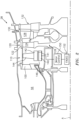
FIG. 2 is a schematic illustration of a turbine section of the gas turbine engine with the driven variable reaction free wheel according to one disclosed non-limiting embodiment. -
FIG. 3 is a schematic illustration of a RELATED ART conventional turbine stage comprising stationary vanes and rotating blades with wheel speed. -
FIG. 4 is a schematic illustration of a RELATED ART conventional turbine stage blade inlet velocity triangle. -
FIG. 5 is a schematic illustration of a RELATED ART conventional turbine stage blade exit velocity triangle. -
FIG. 6 is a schematic illustration of a RELATED ART conventional turbine stage overlay of blade inlet and exit velocity triangles that shows ~50% reaction design. -
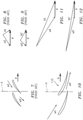
FIG. 7 is a schematic illustration of a RELATED ART conventional compressor blades with rotating wheel speed. -
FIG. 8 is a schematic illustration of a RELATED ART conventional compressor blade inlet velocity triangle. -
FIG. 9 is a schematic illustration of a RELATED ART conventional compressor blade exit velocity triangle. -
FIG. 10 is a schematic illustration of the variable reaction free wheel compressor blades with rotating wheel speed. -
FIG. 11 is a schematic illustration of the variable reaction free wheel compressor blade inlet velocity triangle. -
FIG. 12 is a schematic illustration of the variable reaction free wheel compressor blade exit velocity triangle. -
FIG. 13 is a schematic illustration of variable reaction free wheel turbine stage comprising stationary vanes, variable reaction free wheel compressor, and rotating blades. -
FIG. 14 is a schematic illustration of the variable reaction free wheel turbine stage blade inlet velocity triangle. -
FIG. 15 is a schematic illustration of the variable reaction free wheel turbine stage blade exit velocity triangle. -
FIG. 16 is a schematic illustration of the variable reaction free wheel turbine stage overlay of blade inlet and exit velocity triangles shows lower (<<50%) reaction design. -
FIG. 17 is a schematic illustration of a comparison of turbine blade wheel speeds. -
FIG. 18 is a schematic illustration of a comparison of turbine blade inlet velocity triangles. -
FIG. 19 is a schematic illustration of a comparison of turbine blade exit velocity triangles. -
FIG. 20 is a schematic illustration of a conventional turbine stage overlay of blade inlet and exit velocity triangles shows ~50% reaction design. -
FIG. 21 is a schematic illustration of the variable reaction free wheel turbine stage overlay of blade inlet and exit velocity triangles that shows a lower reaction design and lower Mach numbers for relative flow through the blade cascade, and reduced absolute exit swirl. -
FIG. 22 is a schematic illustration of the variable reaction free wheel turbine blading versus conventional turbine shows slower turbine wheel speed for reduced blade mechanical stress and reduction in blade relative temperature due to slower wheel speed. -
FIG. 23 is a chart of the variable reaction free wheel turbine in operation. -
FIG. 1 schematically illustrates agas turbine engine 20. Thegas turbine engine 20 is disclosed herein as a two-spool turbofan that generally incorporates afan section 22, acompressor section 24, acombustor section 26, and aturbine section 28. Thefan section 22 drives air along a bypass flowpath while thecompressor section 24 drives air along a core flow combustion gas path for compression and communication into thecombustor section 26, then expansion through theturbine section 28. The fan, compressor, and turbine sections may include various architectures that, for example, include a multitude of stages, each with or without various combinations of variable or fixed guide vanes. The sections are defined along a central longitudinal engine axis A. - Although depicted as a turbofan in the disclosed non-limiting embodiment, it should be appreciated that the concepts described herein may be applied to other engine architectures such as turbojets, turboshafts, and three-spool (plus fan) turbofans.
- The
engine 20 generally includes alow spool 30 and ahigh spool 32 mounted for rotation about an engine central longitudinal axis A relative to an enginestatic structure 36 viaseveral bearings 38. Thelow spool 30 generally includes aninner shaft 40 that interconnects afan 42, a low pressure compressor ("LPC") 44 and a low pressure turbine ("LPT") 46. Theinner shaft 40 drives thefan 42 directly or through a gearedarchitecture 48 that drives thefan 42 at a lower speed than thelow spool 30. An exemplary reduction transmission is an epicyclic transmission, such as a planetary or star gear system. - The
high spool 32 includes anouter shaft 50 that interconnects a high pressure compressor ("HPC") 52 and high pressure turbine ("HPT") 54. Acombustor 56 is arranged between thehigh pressure compressor 52 and thehigh pressure turbine 54. Theinner shaft 40 and theouter shaft 50 are concentric and rotate about the engine central longitudinal axis A which is collinear with their longitudinal axes. - Core airflow is compressed by the
LPC 44, then theHPC 52, mixed with the fuel and burned in thecombustor 56, then expanded over theHPT 54 and theLPT 46 which rotationally drive the respectivehigh spool 32 and thelow spool 30 in response to the expansion. Themain engine shafts bearings 38 within thestatic structure 36. - With reference to
FIG. 2 , theturbine section 28 includes a row of Nozzle Guide Vanes (NGVs) 100 located immediately downstream of thecombustor 56 as the first static vane structure upstream of theturbine section 28. TheNGVs 100 are static airfoils that direct the core flow combustion gases from thecombustor 56 to facilitate the conversion of pressure energy into kinetic energy. The combustion gases are also accelerated by theNGVs 100 because of their convergent shape and typically provide a "spin" or a "swirl" in the direction of turbine rotor rotation. - A variable reaction
free wheel 110 is positioned immediately downstream of theNGVs 100. Downstream of the variable reactionfree wheel 110 is aturbine rotor 126. Theturbine rotor 126 includes ashroud assembly 120 within theengine case structure 36 that supports a blade outer air seal (BOAS)assembly 122 proximate to a multiple ofrotor blades 124 of theturbine rotor 126. Downstream of theturbine rotor 126, an array ofvanes 128 that form avane ring 130 completes the stage. One or more additional turbine rotor stages 132 (one shown) may be located downstream thereof in theturbine section 28. Various turbine section architectures may alternatively or additionally be provided inclusive of various combinations of variable or fixed guide vanes. The stator vanes align the core flow combustion gases while the rotor blades collect the energy of the working medium gases and drive the turbine rotors which in turn drives the compressor. - The variable reaction
free wheel 110 is selectively driven to increase energy into the core flow combustion gases from theupstream NGVs 100. The variable reactionfree wheel 110 turbomachinery is essentially a relatively weak compressor with a flow pressure ratio of 1.01 - 1.02 which is lower than a conventional compressor stage (e.g., 1.2 - 1.3). The compression is not quite desirable but the change in swirl from less swirl to more swirl by applying energy to the flow generates some compression. - The variable reaction
free wheel 110 increases swirl as the variable reactionfree wheel 110 is rotationally driven at about 40%-60% of thedownstream turbine rotor 126 speed. The swirl is of a velocity that is nearly tangential relative to the axis of rotation A and is basically pushing the core flow combustion gases in the same direction as thedownstream turbine rotor 126 to augment the swirl from theupstream NGVs 100. - The variable reaction
free wheel 110 generally includes astator 140, and arotor 142 with a multiple of freewheel rotor blades 144. The variable reactionfree wheel 110 is freewheeling in the sense that it is configured to rotate independent of the high pressure turbine and is selectively controlled, i.e., is infinitely variable with respect to thedownstream turbine rotor 126. According to the invention, thestator 140 and therotor 142 form anelectric motor 146 to selectively drive the multiple of freewheel rotor blades 144 in response to acontroller 150. That is, thestator 140 may include anelectromagnet 141 such that therotor 142 is subject to the magnetic field created by thestator 140 to drive therotor 142. The multiple of freewheel rotor blades 144 may be manufactured of a ceramic material or metallic alloy and may be uncooled. As a weak compressor, the airfoil shapes of the freewheel rotor blades 144 of the variable reactionfree wheel 110 are comparable to the airfoil shapes at the tips of the blades of a conventional compressor and are thin in an airfoil shape thickness dimension (t) relative to airfoil chord length dimension (b) and are lower in airfoil camber for compatibility with higher flow Mach numbers and lower aerodynamic losses. The t:b ratio is less than about 15%. The camber of the airfoil shapes is substantially less than the camber of theupstream NGVs 100. The stagger of therotor blades 144 is substantially tangent to the engine centerline axis A and the stagger of theupstream NGVs 100 is relatively less tangent to the engine centerline axis A. The metallicalloy rotor blades 144 can be shape memory alloys that change the camber of the airfoil shapes in response to changes in the electric current of therotor 142 of theelectric motor 146. Moderate changes to the camber of the airfoil shapes of therotor blades 144 with free wheel speed further vary the effect of the free wheel swirl and improve the aerodynamic efficiency of thefree wheel rotor 142 and theturbine rotor 126. The changes in airfoil camber can be scheduled as a function of free wheel speed. - The
controller 150 generally includes a processor, a memory, and an interface. The processor may be any type of known microprocessor having desired performance characteristics. The memory may be any computer readable medium which stores data and control algorithms such as logic as described herein. Thecontroller 150 may, for example, be a portion of a flight control computer, a portion of a Full Authority Digital Engine Control (FADEC) 152, a stand-alone unit or combinations thereof. - With reference to
FIG. 3 , a conventional turbine stage includes a forward cascade of stationary vanes, and an aft cascade of rotating blades that rotate about the engine centerline axis A with wheel speed, U. The flow exiting the cascade of stationary vanes enters the cascade of rotating blades. The core flow combustion gases exiting the cascade of stationary vanes has an absolute velocity, V1, directed aftward toward the cascade of rotating blades and in a direction generally comparable to the cascade of rotating blades. The flow enters the cascade of rotating blades and changes direction within the cascade, exiting at a velocity, W2, relative to the cascade of rotating blades. The conventional turbine stage characteristically has the relative velocity, W2, and the absolute velocity, V1, measured in feet/sec or meters/sec. The velocity, V1, is the velocity of the core flow combustion gases exiting the cascade of stationary vanes. Because the vanes are stationary, the velocity of the core flow combustion gases relative to the cascade of stationary vanes is the same as the absolute velocity of the core flow combustion gases exiting the cascade of stationary vanes. - The cascade of rotating blades rotates about the central longitudinal engine axis A with wheel speed, U. The velocity, W2, is the velocity of the core flow combustion gases exiting the cascade of rotating blades. Because the blades are rotating, the velocity of the core flow combustion gases relative to the blades is not the same as the absolute velocity of the core flow combustion gases passing through the exit of the cascade of rotating blades.
- With reference to
FIG. 4 and 5 , a thermodynamic-aerodynamic analysis of the turbine is describable via the construction of velocity triangles wherein the base of the triangle is the wheel speed, U, of the cascade of rotating blades. A velocity triangle for the inlet of the cascade of rotating blades is shown inFIG. 4 and a velocity triangle for the exit of the cascade of rotating blades is shown inFIG. 5 . For simplicity, the wheel speeds at the inlet and exit of the cascade of rotating blades is assumed to be the same, that is U1 = U2 = U.FIG. 4 represents the velocity triangle for thermo-aerodynamic analysis of the core flow combustion gases exiting the cascade of stationary vanes, relative to the cascade of rotating blades. For the inlet of the cascade of rotating blades, the velocity, V1, of the core flow combustion gases passing through the exit of the cascade of stationary vanes, is one leg of the triangle. Because the blades are moving with wheel speed, U, the cascade of rotating blades see the core flow combustion gases entering as a relative velocity, W1. The velocity of the core flow combustion gases exiting the stationary vanes but relative to the cascade of rotating blades is W1. - Within the reference frame of the cascade of rotating blades, the core flow combustion gases enter the cascade of rotating blades at the relative speed W1. The flow enters the cascade of rotating blades in a swirling angular direction relative to the central longitudinal engine axis A and has a vector component in the same direction as the cascade of rotating blades. In other words, the core flow combustion gases with velocity W1 points partway in the same direction as the wheel speed U and the core flow combustion gases also points partway in the aft direction and parallel to the central longitudinal engine axis A. The velocity, V1, is the longer leg of the velocity triangle compared to the relative velocity, W1.
- For the exit of the cascade of rotating blades (
FIG. 5 ), the relative velocity, W2, of the core flow combustion gases passing through the exit of the cascade of rotating blades is one leg of the triangle. The absolute velocity, V2, of the core flow combustion gases passing through the exit of the cascade of rotating blades is the other leg of the triangle. Within the core flow combustion gases channel constructed by the cascade of rotating blades, the core flow combustion gases turn in a swirling angular direction relative to the central longitudinal engine axis A, away from the direction of the wheel speed, U, and accelerate to a relative velocity, W2. Relative to the cascade of rotating blades, the core flow combustion gases exit the cascade of rotating blades in a swirl angular direction relative to the central longitudinal engine axis A and have a vector component in the opposite direction as the wheel speed of the cascade of rotating blades. In other words, the core flow combustion gases with velocity W2 point partway in the opposite direction as the wheel speed, U, and the core flow combustion gases also point partway in the aft direction and parallel to the central longitudinal engine axis A. - The acceleration of the core flow combustion gases through the cascade of rotating blades increases the relative velocity, W2, greater than that the absolute velocity, V2, of the core flow combustion gases passing through the exit of the cascade of rotating blades. The relative velocity, W2, is the longer leg of the velocity triangle compared to the absolute velocity, V2 (
FIG. 6 ). Per the assumption that the wheel speed, U, is the same at the inlet and exit of the cascade of rotating blades, the velocity triangles (FIG. 4 and 5 ) can be overlayed to compare the velocities. The magnitudes of the inlet absolute velocity vector, V1 and the exit relative velocity vector, W2, are similar. This similarity is typical of an approximately 50% reaction turbine. A 50% reaction turbine has the shape of the turbine stage blade inlet velocity triangle and the shape of the turbine stage blade exit velocity triangle are substantially mirror images about the central longitudinal engine axis A. The corresponding flow relative velocity, W2, and the absolute velocity, V1, are similar in speed measured in feet/sec or meters/sec. The corresponding flow relative velocity, W1, and the absolute velocity, V2, are similar in speed measured in feet/sec or meters/sec. The energy extracted by theturbine rotor blades 124 of theturbine rotor 126 is obtained by a summed change of static pressure of the core flow gases plus the change of the dynamic pressure of the core flow gases. The change in dynamic pressure of the core flow gases is due to the change in kinetic energy of the core flow gases corresponding with the square of the absolute velocity, V2, versus the square of the absolute velocity, V1. - The reaction, R, is defined as the ratio of the energy extracted by the turbine by means of the change of static pressure of the core flow gases (numerator) to the total energy extracted (denominator) as the summed change of static pressure of the core flow gases plus the change of the dynamic pressure of the core flow gases. Larger changes in static pressure increase flow Mach numbers and increase aerodynamic losses in the turbine. The variable reaction
free wheel 110 increases the change in dynamic pressure of the core flow gases and increases the change in kinetic energy of the core flow gases corresponding with the square of the absolute velocity, V2, versus the square of the absolute velocity, V1, and reduces the change of static pressure of the core flow gases within cascade ofrotating blades 144. This reduces the numerator faster than the denominator and allows the reaction, R, to be less than 50% for a substantially similar extraction of energy from the core flow gases. Reducing the change of static pressure of the core flow gases results in a lower exit relative velocity vector, W2, relative to a conventional turbine. A lower exit relative velocity vector, W2, than a conventional turbine results in a lower Mach number, Mw2, and decreases the aerodynamic pressure losses within the core flow combustion gases, and increases the thermodynamic efficiency of the turbine section. - The corresponding flow Mach numbers, Mv1 and Mw2 of the respective velocity vectors, V1 and W2 are similar. A high-level Mach number, Mw2, may be sonic (Mach number is about one) or supersonic (Mach number is substantially greater than one). The high-level Mach number increases the aerodynamic pressure losses within the core flow combustion gases and reduces the thermodynamic efficiency of the
turbine section 28. The size of the triangles as a measure of the speed of the core flow combustion gases exiting the cascade of stationary vanes and passing through the cascade of rotating blades is an attribute caused by the cascade of rotating blades wheel speed U. An increase to the wheel speed U, increases the work output of theturbine section 28, increases Mach number, Mw2, increases the aerodynamic pressure losses within the core flow combustion gases, and reduces the thermodynamic efficiency of the turbine section. - With reference to
FIG. 7 , a conventional compressor cascade of rotating blades rotating about the central longitudinal engine axis A is schematically illustrated. The compressor cascade of rotating blades wheel speed is shown at µ. The flow enters the cascade of rotating blades with a relative velocity ω1 and exits with a relative velocity ω1'. The flow enters with relative velocity ω1 and points partway in the opposite direction as the wheel speed µ and the core flow combustion gases exits with relative velocity ω1' and points partway in the opposite direction as the wheel speed µ. -
FIG. 8 represents the inlet velocity triangle for the conventional compressor cascade of rotating blades.FIG. 9 represents the exit velocity triangle for the conventional compressor cascade of rotating blades. The flow enters with absolute velocity V1 and points partway in the same direction as the wheel speed µ and the core flow combustion gases exits with absolute velocity V1' and points partway in the same direction as the wheel speed µ. The cascade of rotating blades increases the swirl of the core flow combustion gases. In other words, the core flow combustion gases exit the cascade of rotating blades in a swirl angular direction relative to the central longitudinal engine axis A that is angled more closely to the direction of the wheel speed, µ. -
FIG. 10 represents the variable reactionfree wheel 110 cascade of rotating blades rotating about the central longitudinal engine axis A. The variable reactionfree wheel 110 cascade wheel speed is µ. The flow enters the variable reactionfree wheel 110 cascade of rotating blades with a relative velocity ω1 and exits with a relative velocity ω1'. The flow enters with relative velocity ω1 and points partway in the same direction as the wheel speed mu and the core flow combustion gases exits with relative velocity ω1' and points partway in the same direction as the wheel speed µ . Referring briefly toFig. 2 the span length and radial location of thefree wheel blades 144 is substantially the same as the span length and radial location of theNGVs 100 measured radially with respect to the central longitudinal engine axis A. The span and stagger of thefree wheel 110 cascade of rotating blades defines an annular cross-sectional flowpath and flow channel for the core flow combustion gases. Referring again toFig. 10 the stagger of theairfoils 144 of the variable reactionfree wheel 110 is more tangential to the central longitudinal engine axis A than the stagger of thestationary vanes NGVs 100 of the turbine shown inFIG. 3 . The rotatingfree wheel blades 144 create an effectively more tangential stagger than theNGVs 100 alone and increase the tangential swirl entering therotor blades 124 of the variable reaction turbine. The swirl enhancement of the rotatingfree wheel 110 cascade can enable a decreased tangential stagger of theNGVs 100 and decreased swirl imparted by theNGVs 100 while increasing the swirl into therotor blades 124. The cooledNGVs 100 are limited by manufacturing technologies including casting processes to stagger angles that are less tangential than theblades 144 of thefree wheel 110. -
FIG. 11 represents the inlet velocity triangle for the variable reactionfree wheel 110.FIG. 12 represents the exit velocity triangle for the variable reactionfree wheel 110. The flow enters with absolute velocity V1 and points partway in the same direction as the wheel speed µ and the core flow combustion gases exit with absolute velocity V1' and V1' points partway in the same direction as the wheel speed µ. The variable reactionfree wheel 110 accelerates the relative velocity of the core flow combustion gases from an entering value of ω1 to an exit value of ω1'. The free wheel enables a redistribution of a portion of the change of static pressure of the core flow gases from within therotor 124 to thefree wheel 110. The free wheel enables a lower static pressure and lower static temperature, Ts1', of the core flow gases prior to entering theturbine blades 124. - The wheel speed, µ, of the variable reaction
free wheel 110 is substantially lower than the wheel speed, U, of the turbine rotor 126 (FIG. 2 ). The variable reactionfree wheel 110 accelerates the core flow combustion gases both in the absolute and relative rotating frames of reference. The shape of the rotor blades 144 (FIG. 2 ) of the variable reactionfree wheel 110, in one embodiment as inFigure 10 , may be similar to the shape of the airfoils of the compressor shown inFIG. 7 and are mirror imaged in stagger relative to the central longitudinal engine axis A . In another words the airfoils ofFig. 7 and Fig 10 are mirror images in stagger but the same in direction of rotation about the central longitudinal engine axis A. Therotor blades 144 of the variable reactionfree wheel 110 may be relatively thinner in thickness versus chord ratio (t:b) to be suited to a higher inlet flow velocity, V1, and concurrent higher inlet flow Mach number Mω than theNGVs 100. In one embodiment, the t:b of thefree wheel 110 airfoils is less than one-half the t:b of theNGVs 100. In another embodiment the t:b of thefree wheel 110 airfoils is less than one-quarter the t:b of theNGVs 100. In another embodiment, the t:b of thefree wheel 110 airfoils is less than one-eighth the t:b of the NGVs 100 t:b. - The variable reaction
free wheel 110 increases the absolute velocity of the core flow combustion gases entering from a level of V1 to a higher exit absolute velocity, V1'. The variable reactionfree wheel 110 increases the swirl of the core flow combustion gases. In other words, the core flow combustion gases exit the variable reaction free wheel 110 (FIG. 12 ) in an angular direction (or swirl) relative to the central longitudinal engine axis A that is angled closer to the direction of the wheel speed, µ. - With reference to
FIG. 13 the variable reactionfree wheel 110 rotating with wheel speed µ is located aft of theNGVs 100 and forward of theturbine rotor 126 rotating with wheel speed, U'. The variable reactionfree wheel 110 augments the velocity, V1, exiting theNGVs 100 to a higher velocity, V 1', and augments the swirl angular direction relative to the central longitudinal engine axis A that is angled closer to the direction of rotation of theturbine rotor 126. Swirling the inlet flow to theturbine rotor 126 to approach ever closer to the same direction as the direction of rotation of theturbine rotor 126 increases the efficiency of the turbine and enables a reduction in the wheel speed, U', to a value smaller than the wheel speed, U, of a conventional turbine while achieving the same work output as a conventional turbine. -
FIG. 14 represents the velocity triangle for the inlet of the rotating blades of a turbine incorporating the variable reactionfree wheel 110.FIG. 15 represents the velocity triangle for the exit of the rotating blades of a turbine incorporating the variable reactionfree wheel 110. For simplicity, the wheel speeds at the inlet and exit of the cascade of rotating blades is assumed to be the same, that is U1' = U2' = U' (FIG. 16 ). Per the assumption that the wheel speed, U', is the same at the inlet and exit of the cascade of rotating blades, the velocity triangles ofFIG. 14 and 15 can be overlaid (FIG. 16 ) to compare the velocities. The magnitudes of the inlet absolute velocity vector, V1' and the exit relative velocity vector, W2' are substantially different. The magnitude of the inlet absolute velocity vector, V1' is substantially larger than the exit relative velocity vector, W2'. These velocity differences are typical of a turbine with reaction substantially lower than 50%. A 50% reaction turbine has the shape of the turbine stage blade inlet velocity triangle and the shape of the turbine stage blade exit velocity triangle as substantially mirror images about the central longitudinal engine axis A. The corresponding flow relative velocity, W2, and the absolute velocity, V1, are similar in speed measured in feet/sec or meters/sec. The corresponding flow relative velocity, W1, and the absolute velocity, V2, are similar in speed measured in feet/sec or meters/sec. - The reaction, R, is defined as the ratio of the energy extracted by the turbine by the change of static pressure of the core flow gases (numerator) to the total energy extracted (denominator) as the summed change of static pressure of the core flow gases plus the change of the dynamic pressure of the core flow gases. Larger changes in static pressure increase flow Mach numbers and increase aerodynamic losses in the turbine. The variable reaction
free wheel 110 increases the change in dynamic pressure of the core flow gases and increases the change in kinetic energy of the core flow gases corresponding with the square of the absolute velocity, V2', versus the square of the absolute velocity, V1', and reduces the change of static pressure of the core flow gases within the flow channel of the rotating cascade ofblades 124. This reduces the numerator faster than the denominator and allows the reaction, R, to be less than 50% for a substantially similar extraction of energy from the core flow gases. Reducing the change of static pressure of the core flow gases results in a lower exit relative velocity vector, W2', relative to a conventional turbine and a lower exit relative velocity vector, W2', versus the absolute velocity V1'. - The corresponding flow Mach numbers, Mv1' and Mw2' of the respective velocity vectors, V1' and W2' are different. The Mach number, Mw2' is substantially lower than the Mach number Mw2 of a conventional turbine. The lower-level Mach number decreases the aerodynamic pressure losses within the core flow combustion gases and increases the thermodynamic efficiency of the
turbine section 28. The size of the triangles as a measure of the speed of the core flow combustion gases exiting the cascade of stationary vanes and passing through the cascade of rotating blades is an attribute caused by the wheel speed, U'. The slower wheel speed, U', enables smaller Mw2' than the Mach number Mw2 of a conventional turbine. Slower U', alone, decreases the work output of theturbine section 28, however, augmenting V1 to V1' by swirling the inlet flow to theturbine rotor 126 to approach ever closer to the same direction as the direction of rotation of the cascade of rotating blades rotating with wheel speed U' increases the work output of theturbine section 28. - Comparing
FIG. 15 to FIG. 5 illustrates that the variable reactionfree wheel 110 generates the exit relative velocity vector, W2' as being substantially smaller than the exit relative velocity vector, W2. The corresponding flow Mach numbers, Mw2' and Mw2 of the respective velocity vectors, W2' and W2 are different. The Mach number, Mw2' is substantially lower than the Mach number Mw2 of a conventional turbine. The lower-level Mach number decreases the aerodynamic pressure losses within the core flow combustion gases and increases the thermodynamic efficiency of the turbine. -
FIG. 17 overlays the wheel speeds of the cascade of rotating blades for the conventional turbine (FIG. 3 ) and the turbine with the variable reactionfree wheel 110. The wheel speed U' of the rotating cascades of the turbine as augmented by the variable reactionfree wheel 110 is substantially slower than the wheel speed U of the rotating cascades of the conventional turbine. - The free wheel enables a lower static pressure and lower static temperature, Ts1', of the core flow gases prior to entering the
turbine blades 124. The free wheel enables a lower static temperature, Ts1', and lower relative total temperature, Ttrel, of the core flow gases, after the core flow gases enter theturbine blades 124. Ttrel is the total temperature of the core flow gases within the relative frame of reference of the rotating cascade ofturbine blades 124 and is the core flow gas temperature as seen by the turbine blades for cooling purposes. - With reference to
FIG. 17 , and assuming U' is about 90% of U, the variable reactionfree wheel 110 reduces relative total temperatures, Ttrel as follows:
Augmented Rotating Cascade: Tt rel = 81%[U12 / (2gcJ)] + Ts1' - For simplicity, when V1 and V1' are the same, Ts1 and Ts1' are substantially the same and the Ttrel of the augmented cascade of rotating blades is lower due to the slower wheel speed U1' versus U1. The slower wheel speed, U1', and lower Ttrel reduce the stress of the rotating blade cascade and enable less cooling flow for the
turbine blades 124. -
FIG. 18 overlays the inlet velocity triangles for the conventional turbine and the turbine with the variable reactionfree wheel 110. The inlet relative velocities, W1 and W1' are similar in magnitude. The relative total temperatures, Ttrel, of the cascade of rotating blades for a conventional turbine and turbine augmented by the variable reactionfree wheel 110 are calculated as follows: - Conventional Rotating Cascade: Tt rel = U12 / (2gcJ) + Ts1
- Augmented Rotating Cascade: Tt rel' = U1'2 / (2gcJ) + Ts1'
- Where Ts1 and Ts1' are the static temperatures corresponding to the velocities, V1 and V1', respectively The free wheel enables a lower static temperature, Ts1', and lower wheel speed, U1', and results in a lower relative total temperature, Ttrel', of the core flow gases, after the core flow gases enter the flow channel of the rotating cascade of
turbine blades 124. -
FIG. 19 overlays the exit velocity triangles for the conventional turbine and the turbine with the variable reactionfree wheel 110. The relative velocity W2' is substantially lower than the relative velocity W2 of a conventional turbine. The Mach number, Mw2' is substantially lower than the Mach number Mw2 of a conventional turbine. The size of the exit velocity triangles as a measure of the speed of the core flow combustion gases exiting the cascade of rotating blades is an attribute caused by the size of the wheel speed, U', of the cascade of rotating blades versus U such that "Z" is definable as the ratio of the exit relative velocity to the wheel speed as follows:

- From
FIG. 19 , it can be deduced that Z and Z' can be substantially the same. The work output of the turbine per mass flowrate is dh. The following relationship represents the variable reactionfree wheel 110 that can augment and improve the efficiency of a conventional turbine by reducing reaction and wheel speed while achieving substantially the same work output.

- Comparing
FIG. 6 andFIG. 16 W1'/W2' is substantially the same as W1/W2. The variable reactionfree wheel 110 can augment the efficiency of the turbine by reducing reaction and wheel speed while achieving the same work output by adjusting Z', U', W1'/W2', and the speed of the variable reactionfree wheel 110, mu. The speed of the variable reactionfree wheel 110, µ, is controlled independently of the speed U' of theturbine rotor 126. The variable reactionfree wheel 110 can change the work output of the turbine while holding constant the wheel speed, U', of the turbine. In another embodiment, the variable reactionfree wheel 110 can load match the turbine to a load such as a generator by varying the wheel speed µ of the variable reactionfree wheel 110. - With reference to
FIG. 20, 21, and 22 the variable reactionfree wheel 110 enables a smaller exit swirl angle for the absolute flow velocity exiting the rotating cascade ofturbine blades 124. The swirl therein is measured with respect to the central longitudinal engine axis A. The direction of the absolute flow velocity exiting the rotating cascade of turbine blades is closer toward the substantially aft direction which improves the propulsive efficiency of the engine for the case of the turbine being the last stage of flow exiting the engine. The propulsive force of the core flow combustion gases is the vector component parallel to the central longitudinal engine axis A. Swirling flow exiting the engine does not produce as much thrust.FIG 21 . the variable reactionfree wheel 110 enables the engine to generate more thrust by directing the flow toward the same direction as parallel to the engine centerline axis of rotation. The cosine of the smaller angle alpha2' vectors the thrust from the core exit flow to push the aircraft forward substantially coincident with the aircraft flight vector. - With reference to
FIG. 23 , operationally, the speed of the variable reactionfree wheel 110 may be varied independently of the speed of theturbine rotor 126. The magnitude of the speed of the variable reactionfree wheel 110 can be set as a percentage of the variable reactionfree wheel 110 design speed and the magnitude of the speed of theturbine rotor 126 can be set as a percentage of theturbine rotor 126 design speed. The percentage of design speed of thefree wheel 110 versus the percentage of the design speed of theturbine rotor 126 differ on a steady-state basis and as a transient basis depending on the power setting of the engine and demanded changes in engine power setting by the engine control (FADEC). For a steady state power setting of theengine 20, the speed of thefree wheel 110 is scheduled as a function of the speed of theturbine rotor 126 and the speed of the turbine rotor is a function of theengine 20 steady state power setting. For a transient changes in power setting of theengine 20, the speed of thefree wheel 110 is scheduled as a function of the speed of theturbine rotor 126 and the rate of change of the speed of theturbine rotor 126. The foregoing description is exemplary rather than defined by the limitations within. Various non-limiting embodiments are disclosed herein, however, one of ordinary skill in the art would recognize that various modifications and variations in light of the above teachings will fall within the scope of the appended claims. It is therefore to be appreciated that within the scope of the appended claims, the disclosure may be practiced other than as specifically described. For that reason, the appended claims should be studied to determine true scope and content.
Claims (13)
- A turbine section (28) for a gas turbine engine (20), comprising:a first static vane structure (100);a variable reaction free wheel (110) downstream of the first static vane structure (100); anda turbine rotor (126) downstream of the variable reaction free wheel (110), wherein the variable reaction free wheel (110) is configured to augment a swirl of core flow combustion gases from the first static vane structure (100) to the turbine rotor (126);characterised in that:the variable reaction free wheel (110) comprises a stator assembly (140) and a rotor assembly (142), the rotor assembly (142) comprising a multiple of free wheel rotor blades (144);the variable reaction free wheel (110) is driven by an electric motor (146) formed by the stator assembly (140) and the rotor assembly (142); andthe variable reaction free wheel (110) is configured to rotate independently and be selectively controlled with respect to the downstream turbine rotor (126).
- The turbine section (28) as recited in claim 1, wherein the first static vane structure (100) comprises a row of Nozzle Guide Vanes.
- The turbine section (28) as recited in claim 1 or 2, wherein the multiple of free wheel rotor blades (144) are uncooled.
- The turbine section (28) as recited in claim 1, 2 or 3, wherein the multiple of free wheel rotor blades (144) are manufactured of a ceramic material.
- The turbine section (28) as recited in any preceding claim, wherein the multiple of free wheel rotor blades (144) are thinner in thickness versus chord ratio as compared to a multiple of rotor blades (124) of the turbine rotor (126).
- The turbine section (28) as recited in any preceding claim, wherein the multiple of free wheel rotor blades (144) rotate in the same direction as a multiple of rotor blades (124) of the turbine rotor (126).
- The turbine section (28) as recited in any preceding claim, wherein the multiple of free wheel rotor blades (144) increase a swirl prior to the turbine rotor (126).
- The turbine section (28) as recited in any preceding claim, wherein the multiple of free wheel rotor blades (144) provide a pressure flow of 1.01 - 1.02.
- The turbine section (28) as recited in any preceding claim, further comprising a controller (150) to selectively control the speed of the variable reaction free wheel (110) independent of the turbine rotor (126).
- A method of generating thrust for a gas turbine engine (20), comprising:rotating a variable reaction free wheel (110) located downstream of a combustor (56), wherein the variable reaction free wheel (110) is located downstream of a first static vane structure (100) and upstream of a turbine rotor (126) to augment a swirl of a core flow combustion gases from the first static vane structure (100) to the turbine rotor (126);characterised in that:the variable reaction free wheel (110) comprises a stator assembly (140) and a rotor assembly (142), the rotor assembly (142) comprising a multiple of free wheel rotor blades (144);the variable reaction free wheel (110) is driven by an electric motor (146) formed by the stator assembly (140) and the rotor assembly (142); andthe variable reaction free wheel (110) is configured to rotate independently and be selectively controlled with respect to the downstream turbine rotor (126).
- The method as recited in claim 10, wherein augmenting the swirl comprises augmenting the swirl angular direction relative to a centerline (A) of the engine (20) to angle the core flow combustion gases closer to the direction of rotation of the turbine rotor (126).
- The method as recited in any of claims 10 or 11, wherein rotating the variable reaction free wheel (110) comprises driving the variable reaction free wheel (110) independent of the turbine rotor (126).
- The method as recited in claim 12, wherein rotating the variable reaction free wheel (110) comprises driving the variable reaction free wheel (110) independent of the turbine rotor (126) to load match a turbine to a generator load by varying the wheel speed of the variable reaction free wheel (110).
Applications Claiming Priority (1)
| Application Number | Priority Date | Filing Date | Title |
|---|---|---|---|
| US16/299,430 US10907540B2 (en) | 2019-03-12 | 2019-03-12 | Independently controllable wheel for a turbine section of a gas turbine engine |
Publications (2)
| Publication Number | Publication Date |
|---|---|
| EP3708803A1 EP3708803A1 (en) | 2020-09-16 |
| EP3708803B1 true EP3708803B1 (en) | 2023-04-26 |
Family
ID=72422950
Family Applications (1)
| Application Number | Title | Priority Date | Filing Date |
|---|---|---|---|
| EP20162823.7A Active EP3708803B1 (en) | 2019-03-12 | 2020-03-12 | Variable reaction free wheel for a turbine section of a gas turbine engine |
Country Status (2)
| Country | Link |
|---|---|
| US (1) | US10907540B2 (en) |
| EP (1) | EP3708803B1 (en) |
Families Citing this family (1)
| Publication number | Priority date | Publication date | Assignee | Title |
|---|---|---|---|---|
| US11867069B2 (en) * | 2021-06-28 | 2024-01-09 | Rtx Corporation | Hybrid electric variable area turbine |
Citations (1)
| Publication number | Priority date | Publication date | Assignee | Title |
|---|---|---|---|---|
| US20100083669A1 (en) * | 2008-10-08 | 2010-04-08 | Searete Llc, A Limited Liability Corporation Of The State Of Delaware | Hybrid propulsive engine including at least one independently rotatable propeller/fan |
Family Cites Families (9)
| Publication number | Priority date | Publication date | Assignee | Title |
|---|---|---|---|---|
| US4643636A (en) * | 1985-07-22 | 1987-02-17 | Avco Corporation | Ceramic nozzle assembly for gas turbine engine |
| US6981841B2 (en) | 2003-11-20 | 2006-01-03 | General Electric Company | Triple circuit turbine cooling |
| US7140832B2 (en) * | 2005-04-04 | 2006-11-28 | General Electric Company | Method and system for rotating a turbine stator ring |
| US20100083632A1 (en) * | 2008-10-08 | 2010-04-08 | Searete Llc, A Limited Liability Corporation Of The State Of Delaware | Hybrid propulsive engine including at least one independently rotatable compressor rotor |
| GB201308680D0 (en) * | 2013-05-14 | 2013-06-26 | Imp Innovations Ltd | A flow control device for a turbocharger |
| JP6396093B2 (en) | 2014-06-26 | 2018-09-26 | 三菱重工業株式会社 | Turbine rotor cascade, turbine stage and axial turbine |
| GB201509873D0 (en) * | 2015-06-08 | 2015-07-22 | Imp Innovations Ltd | Pulse-optimized flow control |
| GB201615856D0 (en) * | 2016-09-16 | 2016-11-02 | Imp Innovations Ltd | Pulse optimized flow control |
| EP3301276A1 (en) | 2016-09-28 | 2018-04-04 | Siemens Aktiengesellschaft | A rotating device and a compressor assembly for controlling mass flow in a gas turbine |
-
2019
- 2019-03-12 US US16/299,430 patent/US10907540B2/en active Active
-
2020
- 2020-03-12 EP EP20162823.7A patent/EP3708803B1/en active Active
Patent Citations (1)
| Publication number | Priority date | Publication date | Assignee | Title |
|---|---|---|---|---|
| US20100083669A1 (en) * | 2008-10-08 | 2010-04-08 | Searete Llc, A Limited Liability Corporation Of The State Of Delaware | Hybrid propulsive engine including at least one independently rotatable propeller/fan |
Also Published As
| Publication number | Publication date |
|---|---|
| EP3708803A1 (en) | 2020-09-16 |
| US10907540B2 (en) | 2021-02-02 |
| US20200291784A1 (en) | 2020-09-17 |
Similar Documents
| Publication | Publication Date | Title |
|---|---|---|
| EP2518272B1 (en) | Gas turbine engine | |
| US8777554B2 (en) | Intermediate fan stage | |
| US10385871B2 (en) | Method and system for compressor vane leading edge auxiliary vanes | |
| US9341121B2 (en) | Gas turbine engine with intercooling turbine section and intercooling turbine section bypass | |
| US9506353B2 (en) | Lightweight shrouded fan blade | |
| US20230175433A1 (en) | Geared turbofan architecture | |
| US20110146289A1 (en) | Power extraction method | |
| EP2943653B1 (en) | Rotor blade and corresponding gas turbine engine | |
| EP3722565A1 (en) | After-fan system for a gas turbine engine | |
| EP2946102A1 (en) | Relationship between fan and primary exhaust stream velocities in a geared gas turbine engine | |
| US20110150627A1 (en) | Method of operating a fan system | |
| US11473434B2 (en) | Gas turbine engine airfoil | |
| Ahmed et al. | Performance Analysis of Cold Sections of High BYPASS Ratio Turbofan Aeroengine | |
| US11286863B2 (en) | Gas turbine engine geared architecture | |
| EP2336522B1 (en) | Intermediate fan stage | |
| EP3708803B1 (en) | Variable reaction free wheel for a turbine section of a gas turbine engine | |
| US20110146228A1 (en) | Power extraction system | |
| Ponomariov et al. | Using contra-rotating rotors for decreasing sizes and component number in small GTE | |
| EP2290195A2 (en) | Combustor turbine interface for a gas turbine engine | |
| Wilde | The design and performance of high temperature turbines in turbofan engines | |
| US11773866B2 (en) | Repeating airfoil tip strong pressure profile | |
| CA2724610C (en) | Intermediate fan stage | |
| CA2724611A1 (en) | Power extraction system | |
| EP2336491A2 (en) | Turbofan engine with power extraction system | |
| Jeschke et al. | A Novel Gas Generator Concept for Jet Engines Using a Rotating Combustion Chamber |
Legal Events
| Date | Code | Title | Description |
|---|---|---|---|
| PUAI | Public reference made under article 153(3) epc to a published international application that has entered the european phase |
Free format text: ORIGINAL CODE: 0009012 |
|
| STAA | Information on the status of an ep patent application or granted ep patent |
Free format text: STATUS: THE APPLICATION HAS BEEN PUBLISHED |
|
| AK | Designated contracting states |
Kind code of ref document: A1 Designated state(s): AL AT BE BG CH CY CZ DE DK EE ES FI FR GB GR HR HU IE IS IT LI LT LU LV MC MK MT NL NO PL PT RO RS SE SI SK SM TR |
|
| AX | Request for extension of the european patent |
Extension state: BA ME |
|
| STAA | Information on the status of an ep patent application or granted ep patent |
Free format text: STATUS: REQUEST FOR EXAMINATION WAS MADE |
|
| RAP1 | Party data changed (applicant data changed or rights of an application transferred) |
Owner name: RAYTHEON TECHNOLOGIES CORPORATION |
|
| 17P | Request for examination filed |
Effective date: 20210316 |
|
| RBV | Designated contracting states (corrected) |
Designated state(s): AL AT BE BG CH CY CZ DE DK EE ES FI FR GB GR HR HU IE IS IT LI LT LU LV MC MK MT NL NO PL PT RO RS SE SI SK SM TR |
|
| GRAP | Despatch of communication of intention to grant a patent |
Free format text: ORIGINAL CODE: EPIDOSNIGR1 |
|
| STAA | Information on the status of an ep patent application or granted ep patent |
Free format text: STATUS: GRANT OF PATENT IS INTENDED |
|
| RIC1 | Information provided on ipc code assigned before grant |
Ipc: F01D 15/10 20060101ALN20220407BHEP Ipc: F02C 3/00 20060101ALI20220407BHEP Ipc: F01D 17/12 20060101AFI20220407BHEP |
|
| INTG | Intention to grant announced |
Effective date: 20220426 |
|
| RIC1 | Information provided on ipc code assigned before grant |
Ipc: F01D 15/10 20060101ALN20220408BHEP Ipc: F02C 3/00 20060101ALI20220408BHEP Ipc: F01D 17/12 20060101AFI20220408BHEP |
|
| REG | Reference to a national code |
Ref country code: DE Ref legal event code: R079 Ref document number: 602020010019 Country of ref document: DE Free format text: PREVIOUS MAIN CLASS: F02C0003000000 Ipc: F01D0017120000 |
|
| GRAJ | Information related to disapproval of communication of intention to grant by the applicant or resumption of examination proceedings by the epo deleted |
Free format text: ORIGINAL CODE: EPIDOSDIGR1 |
|
| STAA | Information on the status of an ep patent application or granted ep patent |
Free format text: STATUS: REQUEST FOR EXAMINATION WAS MADE |
|
| GRAP | Despatch of communication of intention to grant a patent |
Free format text: ORIGINAL CODE: EPIDOSNIGR1 |
|
| STAA | Information on the status of an ep patent application or granted ep patent |
Free format text: STATUS: GRANT OF PATENT IS INTENDED |
|
| INTC | Intention to grant announced (deleted) | ||
| RIC1 | Information provided on ipc code assigned before grant |
Ipc: F01D 15/10 20060101ALN20220907BHEP Ipc: F02C 3/00 20060101ALI20220907BHEP Ipc: F01D 17/12 20060101AFI20220907BHEP |
|
| INTG | Intention to grant announced |
Effective date: 20220927 |
|
| GRAS | Grant fee paid |
Free format text: ORIGINAL CODE: EPIDOSNIGR3 |
|
| GRAA | (expected) grant |
Free format text: ORIGINAL CODE: 0009210 |
|
| STAA | Information on the status of an ep patent application or granted ep patent |
Free format text: STATUS: THE PATENT HAS BEEN GRANTED |
|
| AK | Designated contracting states |
Kind code of ref document: B1 Designated state(s): AL AT BE BG CH CY CZ DE DK EE ES FI FR GB GR HR HU IE IS IT LI LT LU LV MC MK MT NL NO PL PT RO RS SE SI SK SM TR |
|
| REG | Reference to a national code |
Ref country code: GB Ref legal event code: FG4D |
|
| REG | Reference to a national code |
Ref country code: CH Ref legal event code: EP |
|
| REG | Reference to a national code |
Ref country code: DE Ref legal event code: R096 Ref document number: 602020010019 Country of ref document: DE |
|
| REG | Reference to a national code |
Ref country code: AT Ref legal event code: REF Ref document number: 1562958 Country of ref document: AT Kind code of ref document: T Effective date: 20230515 |
|
| REG | Reference to a national code |
Ref country code: IE Ref legal event code: FG4D |
|
| P01 | Opt-out of the competence of the unified patent court (upc) registered |
Effective date: 20230603 |
|
| REG | Reference to a national code |
Ref country code: LT Ref legal event code: MG9D |
|
| REG | Reference to a national code |
Ref country code: NL Ref legal event code: MP Effective date: 20230426 |
|
| REG | Reference to a national code |
Ref country code: AT Ref legal event code: MK05 Ref document number: 1562958 Country of ref document: AT Kind code of ref document: T Effective date: 20230426 |
|
| PG25 | Lapsed in a contracting state [announced via postgrant information from national office to epo] |
Ref country code: NL Free format text: LAPSE BECAUSE OF FAILURE TO SUBMIT A TRANSLATION OF THE DESCRIPTION OR TO PAY THE FEE WITHIN THE PRESCRIBED TIME-LIMIT Effective date: 20230426 |
|
| PG25 | Lapsed in a contracting state [announced via postgrant information from national office to epo] |
Ref country code: SE Free format text: LAPSE BECAUSE OF FAILURE TO SUBMIT A TRANSLATION OF THE DESCRIPTION OR TO PAY THE FEE WITHIN THE PRESCRIBED TIME-LIMIT Effective date: 20230426 Ref country code: PT Free format text: LAPSE BECAUSE OF FAILURE TO SUBMIT A TRANSLATION OF THE DESCRIPTION OR TO PAY THE FEE WITHIN THE PRESCRIBED TIME-LIMIT Effective date: 20230828 Ref country code: NO Free format text: LAPSE BECAUSE OF FAILURE TO SUBMIT A TRANSLATION OF THE DESCRIPTION OR TO PAY THE FEE WITHIN THE PRESCRIBED TIME-LIMIT Effective date: 20230726 Ref country code: ES Free format text: LAPSE BECAUSE OF FAILURE TO SUBMIT A TRANSLATION OF THE DESCRIPTION OR TO PAY THE FEE WITHIN THE PRESCRIBED TIME-LIMIT Effective date: 20230426 Ref country code: AT Free format text: LAPSE BECAUSE OF FAILURE TO SUBMIT A TRANSLATION OF THE DESCRIPTION OR TO PAY THE FEE WITHIN THE PRESCRIBED TIME-LIMIT Effective date: 20230426 |
|
| RAP4 | Party data changed (patent owner data changed or rights of a patent transferred) |
Owner name: RTX CORPORATION |
|
| PG25 | Lapsed in a contracting state [announced via postgrant information from national office to epo] |
Ref country code: RS Free format text: LAPSE BECAUSE OF FAILURE TO SUBMIT A TRANSLATION OF THE DESCRIPTION OR TO PAY THE FEE WITHIN THE PRESCRIBED TIME-LIMIT Effective date: 20230426 Ref country code: PL Free format text: LAPSE BECAUSE OF FAILURE TO SUBMIT A TRANSLATION OF THE DESCRIPTION OR TO PAY THE FEE WITHIN THE PRESCRIBED TIME-LIMIT Effective date: 20230426 Ref country code: LV Free format text: LAPSE BECAUSE OF FAILURE TO SUBMIT A TRANSLATION OF THE DESCRIPTION OR TO PAY THE FEE WITHIN THE PRESCRIBED TIME-LIMIT Effective date: 20230426 Ref country code: LT Free format text: LAPSE BECAUSE OF FAILURE TO SUBMIT A TRANSLATION OF THE DESCRIPTION OR TO PAY THE FEE WITHIN THE PRESCRIBED TIME-LIMIT Effective date: 20230426 Ref country code: IS Free format text: LAPSE BECAUSE OF FAILURE TO SUBMIT A TRANSLATION OF THE DESCRIPTION OR TO PAY THE FEE WITHIN THE PRESCRIBED TIME-LIMIT Effective date: 20230826 Ref country code: HR Free format text: LAPSE BECAUSE OF FAILURE TO SUBMIT A TRANSLATION OF THE DESCRIPTION OR TO PAY THE FEE WITHIN THE PRESCRIBED TIME-LIMIT Effective date: 20230426 Ref country code: GR Free format text: LAPSE BECAUSE OF FAILURE TO SUBMIT A TRANSLATION OF THE DESCRIPTION OR TO PAY THE FEE WITHIN THE PRESCRIBED TIME-LIMIT Effective date: 20230727 |
|
| PG25 | Lapsed in a contracting state [announced via postgrant information from national office to epo] |
Ref country code: FI Free format text: LAPSE BECAUSE OF FAILURE TO SUBMIT A TRANSLATION OF THE DESCRIPTION OR TO PAY THE FEE WITHIN THE PRESCRIBED TIME-LIMIT Effective date: 20230426 |
|
| PG25 | Lapsed in a contracting state [announced via postgrant information from national office to epo] |
Ref country code: SK Free format text: LAPSE BECAUSE OF FAILURE TO SUBMIT A TRANSLATION OF THE DESCRIPTION OR TO PAY THE FEE WITHIN THE PRESCRIBED TIME-LIMIT Effective date: 20230426 |
|
| REG | Reference to a national code |
Ref country code: DE Ref legal event code: R097 Ref document number: 602020010019 Country of ref document: DE |
|
| PG25 | Lapsed in a contracting state [announced via postgrant information from national office to epo] |
Ref country code: SM Free format text: LAPSE BECAUSE OF FAILURE TO SUBMIT A TRANSLATION OF THE DESCRIPTION OR TO PAY THE FEE WITHIN THE PRESCRIBED TIME-LIMIT Effective date: 20230426 Ref country code: SK Free format text: LAPSE BECAUSE OF FAILURE TO SUBMIT A TRANSLATION OF THE DESCRIPTION OR TO PAY THE FEE WITHIN THE PRESCRIBED TIME-LIMIT Effective date: 20230426 Ref country code: RO Free format text: LAPSE BECAUSE OF FAILURE TO SUBMIT A TRANSLATION OF THE DESCRIPTION OR TO PAY THE FEE WITHIN THE PRESCRIBED TIME-LIMIT Effective date: 20230426 Ref country code: EE Free format text: LAPSE BECAUSE OF FAILURE TO SUBMIT A TRANSLATION OF THE DESCRIPTION OR TO PAY THE FEE WITHIN THE PRESCRIBED TIME-LIMIT Effective date: 20230426 Ref country code: DK Free format text: LAPSE BECAUSE OF FAILURE TO SUBMIT A TRANSLATION OF THE DESCRIPTION OR TO PAY THE FEE WITHIN THE PRESCRIBED TIME-LIMIT Effective date: 20230426 Ref country code: CZ Free format text: LAPSE BECAUSE OF FAILURE TO SUBMIT A TRANSLATION OF THE DESCRIPTION OR TO PAY THE FEE WITHIN THE PRESCRIBED TIME-LIMIT Effective date: 20230426 |
|
| PLBE | No opposition filed within time limit |
Free format text: ORIGINAL CODE: 0009261 |
|
| STAA | Information on the status of an ep patent application or granted ep patent |
Free format text: STATUS: NO OPPOSITION FILED WITHIN TIME LIMIT |
|
| 26N | No opposition filed |
Effective date: 20240129 |
|
| PG25 | Lapsed in a contracting state [announced via postgrant information from national office to epo] |
Ref country code: SI Free format text: LAPSE BECAUSE OF FAILURE TO SUBMIT A TRANSLATION OF THE DESCRIPTION OR TO PAY THE FEE WITHIN THE PRESCRIBED TIME-LIMIT Effective date: 20230426 |
|
| PG25 | Lapsed in a contracting state [announced via postgrant information from national office to epo] |
Ref country code: SI Free format text: LAPSE BECAUSE OF FAILURE TO SUBMIT A TRANSLATION OF THE DESCRIPTION OR TO PAY THE FEE WITHIN THE PRESCRIBED TIME-LIMIT Effective date: 20230426 Ref country code: IT Free format text: LAPSE BECAUSE OF FAILURE TO SUBMIT A TRANSLATION OF THE DESCRIPTION OR TO PAY THE FEE WITHIN THE PRESCRIBED TIME-LIMIT Effective date: 20230426 |
|
| REG | Reference to a national code |
Ref country code: CH Ref legal event code: PL |
|
| PG25 | Lapsed in a contracting state [announced via postgrant information from national office to epo] |
Ref country code: BG Free format text: LAPSE BECAUSE OF FAILURE TO SUBMIT A TRANSLATION OF THE DESCRIPTION OR TO PAY THE FEE WITHIN THE PRESCRIBED TIME-LIMIT Effective date: 20230426 |
|
| PG25 | Lapsed in a contracting state [announced via postgrant information from national office to epo] |
Ref country code: LU Free format text: LAPSE BECAUSE OF NON-PAYMENT OF DUE FEES Effective date: 20240312 |
|
| PG25 | Lapsed in a contracting state [announced via postgrant information from national office to epo] |
Ref country code: MC Free format text: LAPSE BECAUSE OF FAILURE TO SUBMIT A TRANSLATION OF THE DESCRIPTION OR TO PAY THE FEE WITHIN THE PRESCRIBED TIME-LIMIT Effective date: 20230426 |
|
| PG25 | Lapsed in a contracting state [announced via postgrant information from national office to epo] |
Ref country code: LU Free format text: LAPSE BECAUSE OF NON-PAYMENT OF DUE FEES Effective date: 20240312 Ref country code: MC Free format text: LAPSE BECAUSE OF FAILURE TO SUBMIT A TRANSLATION OF THE DESCRIPTION OR TO PAY THE FEE WITHIN THE PRESCRIBED TIME-LIMIT Effective date: 20230426 Ref country code: BG Free format text: LAPSE BECAUSE OF FAILURE TO SUBMIT A TRANSLATION OF THE DESCRIPTION OR TO PAY THE FEE WITHIN THE PRESCRIBED TIME-LIMIT Effective date: 20230426 |
|
| REG | Reference to a national code |
Ref country code: BE Ref legal event code: MM Effective date: 20240331 |
|
| PG25 | Lapsed in a contracting state [announced via postgrant information from national office to epo] |
Ref country code: BE Free format text: LAPSE BECAUSE OF NON-PAYMENT OF DUE FEES Effective date: 20240331 |
|
| PG25 | Lapsed in a contracting state [announced via postgrant information from national office to epo] |
Ref country code: IE Free format text: LAPSE BECAUSE OF NON-PAYMENT OF DUE FEES Effective date: 20240312 |
|
| PG25 | Lapsed in a contracting state [announced via postgrant information from national office to epo] |
Ref country code: IE Free format text: LAPSE BECAUSE OF NON-PAYMENT OF DUE FEES Effective date: 20240312 Ref country code: BE Free format text: LAPSE BECAUSE OF NON-PAYMENT OF DUE FEES Effective date: 20240331 Ref country code: CH Free format text: LAPSE BECAUSE OF NON-PAYMENT OF DUE FEES Effective date: 20240331 |
|
| PG25 | Lapsed in a contracting state [announced via postgrant information from national office to epo] |
Ref country code: CY Free format text: LAPSE BECAUSE OF FAILURE TO SUBMIT A TRANSLATION OF THE DESCRIPTION OR TO PAY THE FEE WITHIN THE PRESCRIBED TIME-LIMIT; INVALID AB INITIO Effective date: 20200312 |
|
| PG25 | Lapsed in a contracting state [announced via postgrant information from national office to epo] |
Ref country code: HU Free format text: LAPSE BECAUSE OF FAILURE TO SUBMIT A TRANSLATION OF THE DESCRIPTION OR TO PAY THE FEE WITHIN THE PRESCRIBED TIME-LIMIT; INVALID AB INITIO Effective date: 20200312 |
|
| REG | Reference to a national code |
Ref country code: DE Ref legal event code: R081 Ref document number: 602020010019 Country of ref document: DE Owner name: RTX CORPORATION (N.D.GES.D. STAATES DELAWARE),, US Free format text: FORMER OWNER: RAYTHEON TECHNOLOGIES CORPORATION, FARMINGTON, CT, US |
|
| PG25 | Lapsed in a contracting state [announced via postgrant information from national office to epo] |
Ref country code: TR Free format text: LAPSE BECAUSE OF FAILURE TO SUBMIT A TRANSLATION OF THE DESCRIPTION OR TO PAY THE FEE WITHIN THE PRESCRIBED TIME-LIMIT Effective date: 20230426 |
|
| PGFP | Annual fee paid to national office [announced via postgrant information from national office to epo] |
Ref country code: GB Payment date: 20260219 Year of fee payment: 7 |
|
| PGFP | Annual fee paid to national office [announced via postgrant information from national office to epo] |
Ref country code: DE Payment date: 20260219 Year of fee payment: 7 |
|
| PGFP | Annual fee paid to national office [announced via postgrant information from national office to epo] |
Ref country code: FR Payment date: 20260219 Year of fee payment: 7 |