EP3708535A1 - Method of manufacturing mos2 having 1t crystal structure - Google Patents
Method of manufacturing mos2 having 1t crystal structure Download PDFInfo
- Publication number
- EP3708535A1 EP3708535A1 EP19215770.9A EP19215770A EP3708535A1 EP 3708535 A1 EP3708535 A1 EP 3708535A1 EP 19215770 A EP19215770 A EP 19215770A EP 3708535 A1 EP3708535 A1 EP 3708535A1
- Authority
- EP
- European Patent Office
- Prior art keywords
- mos
- crystal structure
- gas
- annealing
- carbon
- Prior art date
- Legal status (The legal status is an assumption and is not a legal conclusion. Google has not performed a legal analysis and makes no representation as to the accuracy of the status listed.)
- Granted
Links
Images








Classifications
-
- C—CHEMISTRY; METALLURGY
- C30—CRYSTAL GROWTH
- C30B—SINGLE-CRYSTAL GROWTH; UNIDIRECTIONAL SOLIDIFICATION OF EUTECTIC MATERIAL OR UNIDIRECTIONAL DEMIXING OF EUTECTOID MATERIAL; REFINING BY ZONE-MELTING OF MATERIAL; PRODUCTION OF A HOMOGENEOUS POLYCRYSTALLINE MATERIAL WITH DEFINED STRUCTURE; SINGLE CRYSTALS OR HOMOGENEOUS POLYCRYSTALLINE MATERIAL WITH DEFINED STRUCTURE; AFTER-TREATMENT OF SINGLE CRYSTALS OR A HOMOGENEOUS POLYCRYSTALLINE MATERIAL WITH DEFINED STRUCTURE; APPARATUS THEREFOR
- C30B1/00—Single-crystal growth directly from the solid state
- C30B1/10—Single-crystal growth directly from the solid state by solid state reactions or multi-phase diffusion
-
- D—TEXTILES; PAPER
- D01—NATURAL OR MAN-MADE THREADS OR FIBRES; SPINNING
- D01D—MECHANICAL METHODS OR APPARATUS IN THE MANUFACTURE OF ARTIFICIAL FILAMENTS, THREADS, FIBRES, BRISTLES OR RIBBONS
- D01D5/00—Formation of filaments, threads, or the like
- D01D5/0007—Electro-spinning
- D01D5/0015—Electro-spinning characterised by the initial state of the material
- D01D5/003—Electro-spinning characterised by the initial state of the material the material being a polymer solution or dispersion
-
- C—CHEMISTRY; METALLURGY
- C01—INORGANIC CHEMISTRY
- C01G—COMPOUNDS CONTAINING METALS NOT COVERED BY SUBCLASSES C01D OR C01F
- C01G39/00—Compounds of molybdenum
- C01G39/06—Sulfides
-
- B—PERFORMING OPERATIONS; TRANSPORTING
- B01—PHYSICAL OR CHEMICAL PROCESSES OR APPARATUS IN GENERAL
- B01J—CHEMICAL OR PHYSICAL PROCESSES, e.g. CATALYSIS OR COLLOID CHEMISTRY; THEIR RELEVANT APPARATUS
- B01J21/00—Catalysts comprising the elements, oxides, or hydroxides of magnesium, boron, aluminium, carbon, silicon, titanium, zirconium, or hafnium
- B01J21/18—Carbon
-
- B—PERFORMING OPERATIONS; TRANSPORTING
- B01—PHYSICAL OR CHEMICAL PROCESSES OR APPARATUS IN GENERAL
- B01J—CHEMICAL OR PHYSICAL PROCESSES, e.g. CATALYSIS OR COLLOID CHEMISTRY; THEIR RELEVANT APPARATUS
- B01J27/00—Catalysts comprising the elements or compounds of halogens, sulfur, selenium, tellurium, phosphorus or nitrogen; Catalysts comprising carbon compounds
- B01J27/02—Sulfur, selenium or tellurium; Compounds thereof
- B01J27/04—Sulfides
- B01J27/047—Sulfides with chromium, molybdenum, tungsten or polonium
- B01J27/051—Molybdenum
-
- B—PERFORMING OPERATIONS; TRANSPORTING
- B01—PHYSICAL OR CHEMICAL PROCESSES OR APPARATUS IN GENERAL
- B01J—CHEMICAL OR PHYSICAL PROCESSES, e.g. CATALYSIS OR COLLOID CHEMISTRY; THEIR RELEVANT APPARATUS
- B01J35/00—Catalysts, in general, characterised by their form or physical properties
- B01J35/19—Catalysts containing parts with different compositions
-
- B—PERFORMING OPERATIONS; TRANSPORTING
- B01—PHYSICAL OR CHEMICAL PROCESSES OR APPARATUS IN GENERAL
- B01J—CHEMICAL OR PHYSICAL PROCESSES, e.g. CATALYSIS OR COLLOID CHEMISTRY; THEIR RELEVANT APPARATUS
- B01J35/00—Catalysts, in general, characterised by their form or physical properties
- B01J35/50—Catalysts, in general, characterised by their form or physical properties characterised by their shape or configuration
- B01J35/58—Fabrics or filaments
-
- B—PERFORMING OPERATIONS; TRANSPORTING
- B01—PHYSICAL OR CHEMICAL PROCESSES OR APPARATUS IN GENERAL
- B01J—CHEMICAL OR PHYSICAL PROCESSES, e.g. CATALYSIS OR COLLOID CHEMISTRY; THEIR RELEVANT APPARATUS
- B01J37/00—Processes, in general, for preparing catalysts; Processes, in general, for activation of catalysts
- B01J37/08—Heat treatment
-
- B—PERFORMING OPERATIONS; TRANSPORTING
- B01—PHYSICAL OR CHEMICAL PROCESSES OR APPARATUS IN GENERAL
- B01J—CHEMICAL OR PHYSICAL PROCESSES, e.g. CATALYSIS OR COLLOID CHEMISTRY; THEIR RELEVANT APPARATUS
- B01J6/00—Heat treatments such as Calcining; Fusing ; Pyrolysis
-
- C—CHEMISTRY; METALLURGY
- C25—ELECTROLYTIC OR ELECTROPHORETIC PROCESSES; APPARATUS THEREFOR
- C25B—ELECTROLYTIC OR ELECTROPHORETIC PROCESSES FOR THE PRODUCTION OF COMPOUNDS OR NON-METALS; APPARATUS THEREFOR
- C25B1/00—Electrolytic production of inorganic compounds or non-metals
- C25B1/01—Products
- C25B1/02—Hydrogen or oxygen
-
- C—CHEMISTRY; METALLURGY
- C25—ELECTROLYTIC OR ELECTROPHORETIC PROCESSES; APPARATUS THEREFOR
- C25B—ELECTROLYTIC OR ELECTROPHORETIC PROCESSES FOR THE PRODUCTION OF COMPOUNDS OR NON-METALS; APPARATUS THEREFOR
- C25B11/00—Electrodes; Manufacture thereof not otherwise provided for
- C25B11/04—Electrodes; Manufacture thereof not otherwise provided for characterised by the material
- C25B11/051—Electrodes formed of electrocatalysts on a substrate or carrier
- C25B11/073—Electrodes formed of electrocatalysts on a substrate or carrier characterised by the electrocatalyst material
- C25B11/091—Electrodes formed of electrocatalysts on a substrate or carrier characterised by the electrocatalyst material consisting of at least one catalytic element and at least one catalytic compound; consisting of two or more catalytic elements or catalytic compounds
-
- C—CHEMISTRY; METALLURGY
- C30—CRYSTAL GROWTH
- C30B—SINGLE-CRYSTAL GROWTH; UNIDIRECTIONAL SOLIDIFICATION OF EUTECTIC MATERIAL OR UNIDIRECTIONAL DEMIXING OF EUTECTOID MATERIAL; REFINING BY ZONE-MELTING OF MATERIAL; PRODUCTION OF A HOMOGENEOUS POLYCRYSTALLINE MATERIAL WITH DEFINED STRUCTURE; SINGLE CRYSTALS OR HOMOGENEOUS POLYCRYSTALLINE MATERIAL WITH DEFINED STRUCTURE; AFTER-TREATMENT OF SINGLE CRYSTALS OR A HOMOGENEOUS POLYCRYSTALLINE MATERIAL WITH DEFINED STRUCTURE; APPARATUS THEREFOR
- C30B29/00—Single crystals or homogeneous polycrystalline material with defined structure characterised by the material or by their shape
- C30B29/10—Inorganic compounds or compositions
- C30B29/46—Sulfur-, selenium- or tellurium-containing compounds
-
- D—TEXTILES; PAPER
- D01—NATURAL OR MAN-MADE THREADS OR FIBRES; SPINNING
- D01F—CHEMICAL FEATURES IN THE MANUFACTURE OF ARTIFICIAL FILAMENTS, THREADS, FIBRES, BRISTLES OR RIBBONS; APPARATUS SPECIALLY ADAPTED FOR THE MANUFACTURE OF CARBON FILAMENTS
- D01F1/00—General methods for the manufacture of artificial filaments or the like
- D01F1/02—Addition of substances to the spinning solution or to the melt
- D01F1/10—Other agents for modifying properties
-
- D—TEXTILES; PAPER
- D01—NATURAL OR MAN-MADE THREADS OR FIBRES; SPINNING
- D01F—CHEMICAL FEATURES IN THE MANUFACTURE OF ARTIFICIAL FILAMENTS, THREADS, FIBRES, BRISTLES OR RIBBONS; APPARATUS SPECIALLY ADAPTED FOR THE MANUFACTURE OF CARBON FILAMENTS
- D01F9/00—Artificial filaments or the like of other substances; Manufacture thereof; Apparatus specially adapted for the manufacture of carbon filaments
- D01F9/08—Artificial filaments or the like of other substances; Manufacture thereof; Apparatus specially adapted for the manufacture of carbon filaments of inorganic material
- D01F9/12—Carbon filaments; Apparatus specially adapted for the manufacture thereof
- D01F9/14—Carbon filaments; Apparatus specially adapted for the manufacture thereof by decomposition of organic filaments
- D01F9/20—Carbon filaments; Apparatus specially adapted for the manufacture thereof by decomposition of organic filaments from polyaddition, polycondensation or polymerisation products
- D01F9/21—Carbon filaments; Apparatus specially adapted for the manufacture thereof by decomposition of organic filaments from polyaddition, polycondensation or polymerisation products from macromolecular compounds obtained by reactions only involving carbon-to-carbon unsaturated bonds
- D01F9/22—Carbon filaments; Apparatus specially adapted for the manufacture thereof by decomposition of organic filaments from polyaddition, polycondensation or polymerisation products from macromolecular compounds obtained by reactions only involving carbon-to-carbon unsaturated bonds from polyacrylonitriles
-
- C—CHEMISTRY; METALLURGY
- C01—INORGANIC CHEMISTRY
- C01P—INDEXING SCHEME RELATING TO STRUCTURAL AND PHYSICAL ASPECTS OF SOLID INORGANIC COMPOUNDS
- C01P2002/00—Crystal-structural characteristics
- C01P2002/20—Two-dimensional structures
-
- C—CHEMISTRY; METALLURGY
- C01—INORGANIC CHEMISTRY
- C01P—INDEXING SCHEME RELATING TO STRUCTURAL AND PHYSICAL ASPECTS OF SOLID INORGANIC COMPOUNDS
- C01P2002/00—Crystal-structural characteristics
- C01P2002/70—Crystal-structural characteristics defined by measured X-ray, neutron or electron diffraction data
- C01P2002/76—Crystal-structural characteristics defined by measured X-ray, neutron or electron diffraction data by a space-group or by other symmetry indications
-
- C—CHEMISTRY; METALLURGY
- C01—INORGANIC CHEMISTRY
- C01P—INDEXING SCHEME RELATING TO STRUCTURAL AND PHYSICAL ASPECTS OF SOLID INORGANIC COMPOUNDS
- C01P2002/00—Crystal-structural characteristics
- C01P2002/80—Crystal-structural characteristics defined by measured data other than those specified in group C01P2002/70
- C01P2002/82—Crystal-structural characteristics defined by measured data other than those specified in group C01P2002/70 by IR- or Raman-data
-
- C—CHEMISTRY; METALLURGY
- C01—INORGANIC CHEMISTRY
- C01P—INDEXING SCHEME RELATING TO STRUCTURAL AND PHYSICAL ASPECTS OF SOLID INORGANIC COMPOUNDS
- C01P2002/00—Crystal-structural characteristics
- C01P2002/80—Crystal-structural characteristics defined by measured data other than those specified in group C01P2002/70
- C01P2002/85—Crystal-structural characteristics defined by measured data other than those specified in group C01P2002/70 by XPS, EDX or EDAX data
-
- C—CHEMISTRY; METALLURGY
- C01—INORGANIC CHEMISTRY
- C01P—INDEXING SCHEME RELATING TO STRUCTURAL AND PHYSICAL ASPECTS OF SOLID INORGANIC COMPOUNDS
- C01P2004/00—Particle morphology
- C01P2004/01—Particle morphology depicted by an image
- C01P2004/04—Particle morphology depicted by an image obtained by TEM, STEM, STM or AFM
-
- C—CHEMISTRY; METALLURGY
- C01—INORGANIC CHEMISTRY
- C01P—INDEXING SCHEME RELATING TO STRUCTURAL AND PHYSICAL ASPECTS OF SOLID INORGANIC COMPOUNDS
- C01P2004/00—Particle morphology
- C01P2004/10—Particle morphology extending in one dimension, e.g. needle-like
- C01P2004/16—Nanowires or nanorods, i.e. solid nanofibres with two nearly equal dimensions between 1-100 nanometer
-
- C—CHEMISTRY; METALLURGY
- C01—INORGANIC CHEMISTRY
- C01P—INDEXING SCHEME RELATING TO STRUCTURAL AND PHYSICAL ASPECTS OF SOLID INORGANIC COMPOUNDS
- C01P2004/00—Particle morphology
- C01P2004/80—Particles consisting of a mixture of two or more inorganic phases
- C01P2004/82—Particles consisting of a mixture of two or more inorganic phases two phases having the same anion, e.g. both oxidic phases
-
- D—TEXTILES; PAPER
- D01—NATURAL OR MAN-MADE THREADS OR FIBRES; SPINNING
- D01D—MECHANICAL METHODS OR APPARATUS IN THE MANUFACTURE OF ARTIFICIAL FILAMENTS, THREADS, FIBRES, BRISTLES OR RIBBONS
- D01D10/00—Physical treatment of artificial filaments or the like during manufacture, i.e. during a continuous production process before the filaments have been collected
- D01D10/02—Heat treatment
Definitions
- the present invention relates to a method of manufacturing MoS 2 having a 1T crystal structure. More particularly, the present invention relates to a method of performing phase transition of MoS 2 having a 2H crystal structure (2H-MoS 2 ) as a stable phase to MoS 2 having the 1T crystal structure (1T-MoS 2 ) via reaction with CO gas.
- MoS 2 has a two-dimensional (2D) planar structure. With the development of techniques of separating single layers from a bulk material, various physical properties thereof may be induced, e.g., bandgaps may be changed, by adjusting a structural factor such as the number of stacked layers. Therefore, MoS 2 has drawn attention in various application fields such as electrochemical, electrical, and optical application fields.
- MoS 2 is found in two distinct phases: 1T phase and 2H phase. Since the 1T phase is a metastable phase that is thermodynamically unstable compared to the 2H phase, MoS 2 is mostly formed to have a 2H crystal structure in nature.
- the 2H phase has a hexagonal structure exhibiting electrical properties of semiconductors.
- the 2H phase has no activity at the bottom surface due to symmetrical alignment of sulfur atoms about a Mo atom, and thus it is important to develop a technique for inducing a single-layered structure (vertically aligned structure) of MoS 2 to maximize exposure of edges of the structure for excellent catalytic performance.
- the 1T phase has an octahedral structure exhibiting electrical properties of metals.
- the 1T phase has a very high activity to the bottom surface, and thus extensive research has been conducted to develop a method of inducing the 1T phase.
- the present invention has been proposed to solve various problems including the above problems, and an object of the present invention is to provide a method for quickly and uniformly converting a structure of MoS 2 to a 1T crystal structure regardless of the shape of MoS 2 .
- Another object of the present invention is to provide a method for quickly and uniformly converting a structure of MoS 2 hybridized with other materials such as carbon nanofiber to a 1T crystal structure.
- a method of manufacturing molybdenum disulfide (MoS 2 ) having a 1T crystal structure includes performing phase transition from a 2H crystal structure of MoS 2 to the 1T crystal structure by reacting MoS 2 having the 2H crystal structure with CO gas.
- the performing of phase transition may include annealing the MoS 2 having the 2H crystal structure in an atmosphere including CO gas.
- the performing of phase transition may include annealing the MoS 2 having the 2H crystal structure in an atmosphere including CO gas and CO 2 gas.
- the MoS 2 may be in the form of at least one of bulk, powder, film, wire, and fiber.
- a method of manufacturing MoS 2 having a 1T crystal structure may include forming a MoS 2 -carbon composite by reacting an MoS 2 precursor-organic material composite with CO gas.
- at least one portion of MoS 2 included in the MoS 2 -carbon composite has the 1T crystal structure.
- the MoS 2 precursor-organic material composite may be in the form of fiber.
- the MoS 2 precursor-organic material composite may be prepared by electrospinning.
- the MoS 2 included in the MoS 2 -carbon composite may have a single-layered or a multi-layered structure.
- the forming of the MoS 2 -carbon composite may include annealing the MoS 2 precursor-organic material composite in an atmosphere including CO gas.
- the forming of the MoS 2 -carbon composite may include annealing the MoS 2 precursor-organic material composite in an atmosphere including CO gas CO 2 gas.
- the forming of the MoS 2 -carbon composite may include annealing performed at a temperature in the range of 700°C to 1000°C.
- a catalyst for generating hydrogen prepared according to the above-described method.
- a MoS 2 -carbon composite According to another aspect of the present invention, provided is a MoS 2 -carbon composite.
- the MoS 2 -carbon composite includes a carbon structure in the form of fibers and MoS 2 distributed in the carbon structure.
- the MoS 2 included in the MoS 2 -carbon composite may have a single-layered or a multi-layered structure.
- At least one portion of the MoS 2 may have a 1T crystal structure.
- the present invention provides a method of converting a crystal structure of MoS 2 by reacting MoS 2 or a MoS 2 precursor with carbon monoxide (CO) gas.
- CO is one of the representative reductive gases and the present inventors have found that CO reacts with sulfur (S) contained in MoS 2 to induce S-vacancies therein as shown in Reaction Scheme1 below, resulting in formation of MoS 2 having a 1T crystal structure via atomic diffusion and rearrangement by the S-vacancies.
- the S-vacancy refers to an empty lattice point of a crystal lattice of MoS 2 from which an S atom is removed.
- MoS 2 + ⁇ CO(g) MoS 2- ⁇ + ⁇ COS(g) (where, MOS 2- ⁇ refers to a state in which ⁇ S-vacancies are present in MoS 2 and a stoichiometric value of S is reduced by ⁇ from 2.)
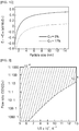
- FIG. 1A shows free energy of S-vacancy formation ( ⁇ E f ) calculated according to Density Functional Theory (DFT) using S-vacancy concentration as a variable under typical implementation conditions.
- the typical implementation conditions were set based on results measured in experiments and include a temperature of 800°C, a CO partial pressure of 0.5 atm, a CO 2 partial pressure of 0.5 atm, and a COS partial pressure of 10 -5 atm.
- (b) of FIG. 1 shows differences between crystal structure energy (E 1T' ) of 1T'-MoS 2 and crystal structure energy (E 2H ) of 2H-MoS 2 according to S-vacancy concentrations.
- the 1T' structure is a distorted structure of the 1T structure and calculation results show that the 1T' structure is more stable than the 1T structure.
- the 1T' structure and the 1T structure have similar properties and it is difficult to distinguish one from the other by experiments, and thus the 1T structure may be used as a generic name for both.
- a free energy of S-vacancy formation ( ⁇ E f ) is an almost constant value of about -1 eV, when the S-vacancy concentration is low (below 9%) under the typical implementation conditions.
- an ⁇ E f value less than 0 indicates that S-vacancy formation reaction occurs spontaneously.
- the S-vacancy concentration exceeds 9%, the ⁇ E f value begins to increase.
- the ⁇ E f value is zero, when the S-vacancy concentration reaches about 17% and the ⁇ E f value exceeds 0, when the S-vacancy concentration is greater than 17%. This means that an equilibrium S-vacancy concentration is about 17%, and thus the S-vacancy concentration in the MoS 2 may be expected to be about 17% under the typical implementation conditions.
- the difference between the crystal structure energy of 2H-MoS 2 and the crystal structure energy of 1T'-MoS 2 is considerably affected by the particle size of MoS 2 .
- the 1T' structure becomes more stable.
- the S-vacancy concentration is 0% and the particle size is about 2 nm or less, it may be confirmed that the 1T' structure is more stable than the 2H structure.
- thermodynamic stability of the 1T' crystal structure tends to be improved with an increased S-vacancy concentration caused by the reaction with the CO gas.
- a decrease in the difference of thermodynamic energy between the 2H and 1T' crystal structures may be understood as an increase in the probability of phase transition from the 2H crystal structure to the 1T' crystal structure.
- the 1T' crystal structure tends to be more stable as the particle size of MoS 2 decreases. In this case, especially in the absence of S-vacancy, the 1T' crystal structure becomes more stable than the 2H crystal structure when the particle size is 2 nm or less.
- the S-vacancy concentration reaches the equilibrium concentration of 17% via reaction with CO gas and the particle size is 7 nm or less, the 1T' crystal structure becomes more stable, causing spontaneous phase transition.
- Annealing MoS 2 in a CO atmosphere may be performed for reaction between CO and MoS 2 .
- CO gas may be introduced into the annealing furnace while heating the annealing furnace at a predetermined temperature.
- the annealing furnace may be used in the atmosphere and may create a vacuum.
- the MoS 2 a target of reaction with CO gas
- the MoS 2 may be in various forms such as in the form of bulk, powder, film, wire, and fiber, without being limited to a particular form.
- pure MoS 2 may be present alone or may be mixed or combined with other materials. This may be possible because the reactant that reacts with MoS 2 to induce the 1T crystal structure is CO in a gaseous state.
- a MoS 2 precursor used to chemically synthesize MoS 2 may also be a target of reaction with CO.
- the MoS 2 precursor may include ammonium tetrathiomolybdate (ATTM).
- a composite of a MoS 2 precursor and an organic material may be a target of reaction with CO.
- the MoS 2 precursor may include ammonium tetrathiomolybdate (ATTM, (NH 4 ) 2 MoS 4 )
- the organic material may include polyacrylonitrile (PAN) forming a hydrogen bond with the ammonium tetrathiomolybdate.
- the composite may be in the form of fiber, for example, prepared by electrospinning that is a method of producing fiber by applying electrostatic repulsive force. In electrospinning, a thickness of nanofiber may easily be adjusted according to a magnitude of voltage of several tens of kV applied to a solution and a length of fiber over 100 ⁇ m may be realized.
- the MoS 2 precursor-organic material composite in the form of nanofiber may be converted into MoS 2 -carbon nanofiber via reaction with CO gas, and at least one portion of MoS 2 included in the MoS 2 -carbon nanofiber may have the 1T crystal structure.
- Annealing temperature for reaction between MoS 2 and CO may be adjusted according to a partial pressure of CO gas in the annealing furnace, for example, may be in the range of 700°C to 1000°C.
- CO gas alone may be added to the annealing furnace or CO gas diluted in an inert gas such as N 2 or Ar may be added to the annealing furnace. Alternatively, a mixed gas of CO and CO 2 may be added thereto.
- oxygen may be generated in an small amount corresponding to an equilibrium pressure of the reaction represented by Reaction Scheme 2 during the annealing process.
- a microstructure of the composite including MoS 2 may be controlled by using the oxygen partial pressure generated in a small amount.
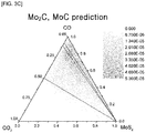
- FIGS. 3A to 3C shows amounts of reaction products according to a concentration of each component as three-component phase diagrams of CO-CO 2 -MoS 2 .
- FIG. 3A shows the amount of MoS 2
- FIG. 3B shows the amount of MoO 2
- FIG. 3C shows a sum of the amounts of Mo 2 C and MoC.
- MoS 2 powder having a 2H crystal structure was prepared.
- the MoS 2 powder was placed in an annealing furnace at ambient pressure and heated at a temperature of 800°C while simultaneously supplying CO gas into the annealing furnace at a flow rate of 80 sccm and CO 2 gas thereinto at a flow rate of 120 sccm.
- X-ray photoelectron spectroscopy was performed on products of Experimental Examples 1 and 2 to observe differences of crystal structures before and after CO gas annealing, and the results are shown in FIGS. 4 and 5 .
- the XPS analysis was performed by using intensities of peaks corresponding to energy levels of Mo 3d 3/2 and Mo 3d 5/2 orbitals of MoS 2 having the 2H and 1T crystal structures.
- a MoS 2 single layer was separated from the MoS 2 powder of Experimental Example 1 by sonication and a crystal structure thereof was analyzed by using a high-resolution transmission electron microscope (HRTEM).
- HRTEM high-resolution transmission electron microscope
- the MoS 2 powder has the 2H crystal structure before CO gas annealing.
- a mixed phase of the 1T structure and the 2T structure is observed.
- two layers of the 1T crystal structures constitute a unit of the 2T structure and physical and chemical properties of the 2T crystal structure are known to be similar to those of the 1T crystal structure.
- both the 2H crystal structure and the 1T+2H crystal structure are observed in a single layer as shown in FIG. 6C . This indicates that the crystal structure of the sample is being converted from the 2H crystal structure into the 1T+2T crystal structure.
- MoS 2 -carbon nanofibers (hereinafter, referred to as "MoS 2 /C nanofibers") were prepared by electrospinning and calcination.
- First, 1.4 g of ammonium tetrathiomolybdate (ATTM) was dissolved in 5 g of N,N-dimethylformamide (DMF) at 120°C for 2 hours while stirring, and 0.7855 g of polyacrylonitrile (PAN, Mw 150,000 g/mol) was dissolved in 5 g of DMF at 120°C for 2 hours while stirring.
- APM ammonium tetrathiomolybdate
- PAN polyacrylonitrile
- the two solutions were mixed and stirred for 10 hours.
- the mixed solution was added to a syringe of an electrospinning apparatus and a potential of 15 kV was set between a metal tip of the syringe and a collector, and then the mixed solution was sprayed at a rate of 0.3 ml/h using a syringe pump to produce ATTM-PAN nanofibers.
- the produced ATTM+PAN nanofibers were converted into MoS 2 /C nanofibers via chemical reactions such as thermal decomposition and oxidation during CO gas annealing.
- CO gas annealing was performed by using a tube furnace. The annealing was performed while flowing a CO/CO 2 gas mixture at 800°C for 1 hour to 5 hours.
- the CO/CO 2 gas mixture was prepared using CO and CO 2 gases each having a purity of 99.9% by adjusting a ratio of CO:CO 2 using a mass flow controller (MFC). Details of Experimental Examples 3 to 10 are shown in Table 1 below.
- the crystal structures of the manufactured MoS 2 /C nanofibers were identified by X-ray photoelectron spectroscopy (XPS) and Raman spectroscopy.
- FIG. 7 are graphs illustrating XPS measurement results of the MoS 2 /C nanofibers manufactured according to the experimental examples of the present invention.
- (a) to (d) of FIG. 7 show XPS measurement results of the MoS 2 /C nanofibers according to Experimental Examples 3 to 6 after annealing for 1 hour according to the CO flow ratio.
- (e) to (h) of FIG. 7 show measurement results of the MoS 2 /C nanofibers according to Experimental Examples 7 to 10 after annealing for 5 hours according to the CO flow ratio.
- peaks of 1T-MoS 2 are observed by CO gas annealing. Also, as the CO flow ratio and the annealing time increase, a peak intensity of 1T-MoS 2 increases and an energy of a peak of 2H-MoS 2 is relatively lowered. It may be understood that the higher the CO flow ratio and the longer the annealing time, the better the conversion from 2H-MoS 2 to 1T-MoS 2 . In addition, according to quantitative analysis by deconvolution of XPS results, as the CO flow ratio increases, the ratio of the 1T phase tends to increase and it was confirmed that the 1T phase was formed up to about 70% in Experimental Example 6.
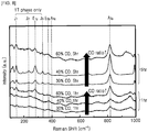
- FIG. 8 shows Raman spectrum measurement results of MoS 2 /C nanofibers manufactured according to Experimental Examples 4 to 6 and Experimental Examples 8 to 10 according to the present invention.
- J 1 , J 2 , and J 3 peaks that were obtainable only in the 1T phase were identified regardless of the CO flow ratio and the annealing time, and thus it was confirmed that 1T-MoS 2 was formed.
- FIG. 9A shows Fourier transform results of the EXAFS measurement results of Experimental Examples 7 to 10. Referring to (a) of FIG. 9 , it may be confirmed that the peak intensity corresponding to the Mo-S coordination number decreases as the CO flow ratio increases. Referring to FIG.
- FIGS. 10A to 10F show transmission electron microscope images of microstructures of MoS 2 /C nanofibers according to experimental examples of the present invention.
- FIGS. 10A to 10C show results of Experimental Examples 4 to 6 and
- FIGS. 10D to 10F show results of Experimental Examples 8 to 10.
- the MoS 2 /C nanofibers according to the experimental examples of the present invention have a structure in which a single-layer of MoS 2 is formed or multi-layers of MoS 2 are stacked in the fibrous structure formed of carbon.
- the number of stacked layers of MoS 2 and the length of MoS 2 increase. This is because the combustion amount of carbon increases as the CO flow ratio decreases and the annealing time increases.
- ATTM-PAN nanofibers prepared in the same manner as in Experimental Examples 3 to 10 were annealed at 800°C for 5 hours in an oxygen atmosphere instead of the CO atmosphere to prepare samples of Experimental Examples 11 and 12.
- the oxygen partial pressures were 0.3 Torr and 0.4 Torr in Experimental Examples 11 and 12, respectively.
- XPS analysis results thereof are shown in FIG. 11 .
- the products had a considerably low 1T structure ratio.
- the ratios of the 1T structures according to Experimental Examples 11 and 12 were about 0% and 25%, respectively.
- Performance of the MoS 2 /C nanofibers prepared according to experimental examples as hydrogen-generating catalysts was measured. 8 mg of each of the MoS 2 /C nanofiber samples prepared according to Experimental Examples 9, 11, and 12, 800 ⁇ l of deionized water, 200 ⁇ l of ethanol, and a fluorine-based Nafion resin solution were mixed and sonicated for 30 minutes to prepare catalyst measurement inks.
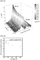
- FIGS. 12A and 12B show graphs illustrating measurement results of hydrogen-generating catalytic characteristics of the MoS 2 /C nanofibers manufactured according to Experimental Examples 9, 11, and 12.
- FIG. 12B is a graph illustrating comparison results of hydrogen-generating catalytic characteristics of the MoS 2 -based materials with respect to overvoltage and Tafel slope. As a result, it was confirmed that the MoS 2 according to the present invention had the best performance among the conventional MoS 2 -based hydrogen-generating catalysts reported so far in both conditions.
- the effect of quickly and uniformly converting the structure of MoS 2 into the 1T-MoS 2 structure regardless of the shape of MoS 2 may be obtained.
- the effect of quickly and uniformly converting the structure of MoS 2 combined with other materials such as carbon nanofiber into the 1T-MoS 2 structure may also be obtained.
Landscapes
- Chemical & Material Sciences (AREA)
- Organic Chemistry (AREA)
- Engineering & Computer Science (AREA)
- Chemical Kinetics & Catalysis (AREA)
- Materials Engineering (AREA)
- Metallurgy (AREA)
- Inorganic Chemistry (AREA)
- Textile Engineering (AREA)
- Physics & Mathematics (AREA)
- Thermal Sciences (AREA)
- Crystallography & Structural Chemistry (AREA)
- Electrochemistry (AREA)
- General Chemical & Material Sciences (AREA)
- Manufacturing & Machinery (AREA)
- Dispersion Chemistry (AREA)
- Mechanical Engineering (AREA)
- Catalysts (AREA)
Abstract
Description
- This application claims the benefit of Korean Patent Application No.
10-2019-0028798, filed on March 13, 2019 - The present invention relates to a method of manufacturing MoS2 having a 1T crystal structure. More particularly, the present invention relates to a method of performing phase transition of MoS2 having a 2H crystal structure (2H-MoS2) as a stable phase to MoS2 having the 1T crystal structure (1T-MoS2) via reaction with CO gas.
- MoS2 has a two-dimensional (2D) planar structure. With the development of techniques of separating single layers from a bulk material, various physical properties thereof may be induced, e.g., bandgaps may be changed, by adjusting a structural factor such as the number of stacked layers. Therefore, MoS2 has drawn attention in various application fields such as electrochemical, electrical, and optical application fields.
- Particularly, depending on the arrangement of sulfur atoms, MoS2 is found in two distinct phases: 1T phase and 2H phase. Since the 1T phase is a metastable phase that is thermodynamically unstable compared to the 2H phase, MoS2 is mostly formed to have a 2H crystal structure in nature. The 2H phase has a hexagonal structure exhibiting electrical properties of semiconductors. In terms of hydrogen-generating catalytic characteristics, the 2H phase has no activity at the bottom surface due to symmetrical alignment of sulfur atoms about a Mo atom, and thus it is important to develop a technique for inducing a single-layered structure (vertically aligned structure) of MoS2 to maximize exposure of edges of the structure for excellent catalytic performance.
- On the other hand, the 1T phase has an octahedral structure exhibiting electrical properties of metals. In terms of hydrogen-generating catalytic characteristics, the 1T phase has a very high activity to the bottom surface, and thus extensive research has been conducted to develop a method of inducing the 1T phase.
- As methods of inducing the 1T-MoS2 structure developed to data, a method of supplying electrons by substitutional doping of Re, Tc, Mn, and the like, a method of supplying electrons by intercalating alkali metal such as Li or a ligand, a method of inducing a pressure in a layer, and a method of forming empty spaces at S sites using plasma have been reported. However, impurities are inevitably included therein according to these methods, thereby deteriorate physical properties thereof. Although the impurities are removed by performing an additional process after conversion to the 1T phase, the 1T phase tends to easily return to the 2H phase due to very low stability thereof. Also, these methods require a very long processing time over 48 hours to obtain the 1T-MoS2 structure, are not suitable for mass production, and entail considerable production costs.
- The present invention has been proposed to solve various problems including the above problems, and an object of the present invention is to provide a method for quickly and uniformly converting a structure of MoS2 to a 1T crystal structure regardless of the shape of MoS2.
- Another object of the present invention is to provide a method for quickly and uniformly converting a structure of MoS2 hybridized with other materials such as carbon nanofiber to a 1T crystal structure.
- However, these problems to be solved are illustrative and the scope of the present invention is not limited thereby.
- Additional aspects will be set forth in part in the description which follows and, in part, will be apparent from the description, or may be learned by practice of the presented embodiments.
- According to an aspect of the present invention to achieve the object, provided is a method of manufacturing molybdenum disulfide (MoS2) having a 1T crystal structure. The method includes performing phase transition from a 2H crystal structure of MoS2 to the 1T crystal structure by reacting MoS2 having the 2H crystal structure with CO gas.
- According to an embodiment, the performing of phase transition may include annealing the MoS2 having the 2H crystal structure in an atmosphere including CO gas.
- According to an embodiment, the performing of phase transition may include annealing the MoS2 having the 2H crystal structure in an atmosphere including CO gas and CO2 gas.
- According to an embodiment, the MoS2 may be in the form of at least one of bulk, powder, film, wire, and fiber.
- According to another aspect of the present invention, provided is a method of manufacturing MoS2 having a 1T crystal structure. The method may include forming a MoS2-carbon composite by reacting an MoS2 precursor-organic material composite with CO gas. In this regard, at least one portion of MoS2 included in the MoS2-carbon composite has the 1T crystal structure.
- According to an embodiment, the MoS2 precursor-organic material composite may be in the form of fiber.
- According to an embodiment, the MoS2 precursor-organic material composite may be prepared by electrospinning.
- According to an embodiment, the MoS2 included in the MoS2-carbon composite may have a single-layered or a multi-layered structure.
- According to an embodiment, the forming of the MoS2-carbon composite may include annealing the MoS2 precursor-organic material composite in an atmosphere including CO gas.
- According to an embodiment, the forming of the MoS2-carbon composite may include annealing the MoS2 precursor-organic material composite in an atmosphere including CO gas CO2 gas.
- According to an embodiment, the forming of the MoS2-carbon composite may include annealing performed at a temperature in the range of 700°C to 1000°C.
- According to another aspect of the present invention, provided is a catalyst for generating hydrogen prepared according to the above-described method.
- According to another aspect of the present invention, provided is a MoS2-carbon composite.
- The MoS2-carbon composite includes a carbon structure in the form of fibers and MoS2 distributed in the carbon structure.
- According to an embodiment, the MoS2 included in the MoS2-carbon composite may have a single-layered or a multi-layered structure.
- According to an embodiment, at least one portion of the MoS2 may have a 1T crystal structure.
- These and/or other aspects will become apparent and more readily appreciated from the following description of the embodiments, taken in conjunction with the accompanying drawings in which:
-
FIGS. 1A to 1C show graphs illustrating free energy of formation of S-vacancies formed in MoS2 via reaction with CO gas and calculated according to DFT and 1T phase stability according to S-vacancy concentration and particle size of MoS2; -
FIG. 2 is a graph illustrating equilibrium oxygen partial pressures according to CO:CO2 flow ratio; -
FIGS. 3A to 3C show graphs illustrating amounts of generated MoS2, MoO2, Mo2C, and MoC in a three-component phase diagram of CO-CO2-MoS2 at 800°C at 1 atm; -
FIGS. 4 and5 are graphs showing X-ray photoelectron spectroscopy (XPS) results to measure formation of a 1T structure in MoS2 powder and a MoS2 precursor according to experimental examples of the present invention; -
FIGS. 6A to 6C show high-resolution transmission electron microscope images obtained to identify formation of 1T of MoS2 powder; -
FIG. 7 shows graphs illustrating XPS measurement results of MoS2/C nanofibers manufactured according to experimental examples of the present invention; -
FIG. 8 is a graph illustrating Raman spectrum measurement results of MoS2/C nanofibers manufactured according to experimental examples of the present invention; -
FIGS. 9A and 9B show graphs illustrating extended X-ray absorption fine structure (EXAFS) measurement results of Mo in the MoS2/C nanofibers according to experimental examples of the present invention; -
FIGS. 10A to 10F show transmission electron microscope images of microstructures of MoS2/C nanofibers according to experimental examples of the present invention; -
FIG. 11 shows graphs illustrating XPS measurement results of MoS2/C nanofibers annealed in an oxygen atmosphere according to experimental examples of the present invention; and -
FIGS. 12A and 12B show graphs illustrating hydrogen-generating catalytic characteristics of MoS2/C nanofibers according to experimental examples of the present invention. - In the following detailed description, reference is made to the accompanying drawings that show, by way of illustration, specific embodiments in which the invention may be practiced. These embodiments are described in sufficient detail to enable those skilled in the art to practice the invention. It is to be understood that the various embodiments of the invention, although different, are not necessarily mutually exclusive. For example, a particular feature, structure, or characteristic described herein, in connection with one embodiment, may be implemented within other embodiments without departing from the spirit and scope of the invention. In addition, it is to be understood that the location or arrangement of individual elements within each disclosed embodiment may be modified without departing from the spirit and scope of the invention. The following detailed description is, therefore, not to be taken in a limiting sense, and the scope of the present invention is defined only by the appended claims, appropriately interpreted, along with the full range of equivalents to which the claims are entitled. In the drawings, like numerals refer to the same or similar functionality throughout the several views and length, areas, thicknesses, and shapes of elements in the drawings may be exaggerated for descriptive convenience.
- Hereinafter, embodiments of the present invention will be described in detail with reference to the accompanying drawings so that these embodiments may be readily implemented by those skilled in the art.
- The present invention provides a method of converting a crystal structure of MoS2 by reacting MoS2 or a MoS2 precursor with carbon monoxide (CO) gas. CO is one of the representative reductive gases and the present inventors have found that CO reacts with sulfur (S) contained in MoS2 to induce S-vacancies therein as shown in Reaction Scheme1 below, resulting in formation of MoS2 having a 1T crystal structure via atomic diffusion and rearrangement by the S-vacancies. The S-vacancy refers to an empty lattice point of a crystal lattice of MoS2 from which an S atom is removed.
Reaction Scheme 1 MoS2+δ·CO(g)=MoS2-δ+δ·COS(g)
(where, MOS2-δ refers to a state in which δ S-vacancies are present in MoS2 and a stoichiometric value of S is reduced by δ from 2.) -
FIG. 1A shows free energy of S-vacancy formation (ΔEf) calculated according to Density Functional Theory (DFT) using S-vacancy concentration as a variable under typical implementation conditions. The typical implementation conditions were set based on results measured in experiments and include a temperature of 800°C, a CO partial pressure of 0.5 atm, a CO2 partial pressure of 0.5 atm, and a COS partial pressure of 10-5 atm. Meanwhile, (b) ofFIG. 1 shows differences between crystal structure energy (E1T') of 1T'-MoS2 and crystal structure energy (E2H) of 2H-MoS2 according to S-vacancy concentrations. Here, the 1T' structure is a distorted structure of the 1T structure and calculation results show that the 1T' structure is more stable than the 1T structure. In general, the 1T' structure and the 1T structure have similar properties and it is difficult to distinguish one from the other by experiments, and thus the 1T structure may be used as a generic name for both. (C) ofFIG. 1 shows E1T'-E2H values calculated according to particles sizes of MoS2, in the absence of S-vacancy (Cv=0%) and at an equilibrium S-vacancy concentration (Cv=17%). - Referring to
FIG. 1A , a free energy of S-vacancy formation (ΔEf) is an almost constant value of about -1 eV, when the S-vacancy concentration is low (below 9%) under the typical implementation conditions. In this regard, an ΔEf value less than 0 indicates that S-vacancy formation reaction occurs spontaneously. When the S-vacancy concentration exceeds 9%, the ΔEf value begins to increase. The ΔEf value is zero, when the S-vacancy concentration reaches about 17% and the ΔEf value exceeds 0, when the S-vacancy concentration is greater than 17%. This means that an equilibrium S-vacancy concentration is about 17%, and thus the S-vacancy concentration in the MoS2 may be expected to be about 17% under the typical implementation conditions. - Meanwhile, referring to
FIG. 1B , it may be confirmed that a difference between the crystal structure energy of 2H-MoS2 as a stable phase and the crystal structure energy of 1T'-MoS2 decreases as the S-vacancy concentration increases in MoS2. This indicates that thermodynamic stability of the 1T'-MoS2 crystal structure relatively increases as the S-vacancy concentration increases in the crystal lattice of MoS2. - Meanwhile, referring to
FIG. 1C , the difference between the crystal structure energy of 2H-MoS2 and the crystal structure energy of 1T'-MoS2 is considerably affected by the particle size of MoS2. As the particle size decreases, the 1T' structure becomes more stable. When the S-vacancy concentration is 0% and the particle size is about 2 nm or less, it may be confirmed that the 1T' structure is more stable than the 2H structure. When the S-vacancy concentration reaches an equilibrium concentration under the conditions according to an embodiment of the present invention, the 1T' structure becomes more stable at a particle size below 7 nm (Cv=17%). - Based thereon, it may be inferred that once S-vacancies are formed in MoS2 by CO gas via the reaction represented by
Reaction Scheme 1 above, thermodynamic stability of the 1T' crystal structure tends to be improved with an increased S-vacancy concentration caused by the reaction with the CO gas. A decrease in the difference of thermodynamic energy between the 2H and 1T' crystal structures may be understood as an increase in the probability of phase transition from the 2H crystal structure to the 1T' crystal structure. Also, the 1T' crystal structure tends to be more stable as the particle size of MoS2 decreases. In this case, especially in the absence of S-vacancy, the 1T' crystal structure becomes more stable than the 2H crystal structure when the particle size is 2 nm or less. When the S-vacancy concentration reaches the equilibrium concentration of 17% via reaction with CO gas and the particle size is 7 nm or less, the 1T' crystal structure becomes more stable, causing spontaneous phase transition. - Annealing MoS2 in a CO atmosphere may be performed for reaction between CO and MoS2. For example, after MoS2 is placed in an annealing furnace, CO gas may be introduced into the annealing furnace while heating the annealing furnace at a predetermined temperature. The annealing furnace may be used in the atmosphere and may create a vacuum.
- In the present invention, the MoS2, a target of reaction with CO gas, may be in various forms such as in the form of bulk, powder, film, wire, and fiber, without being limited to a particular form. Alternatively, pure MoS2 may be present alone or may be mixed or combined with other materials. This may be possible because the reactant that reacts with MoS2 to induce the 1T crystal structure is CO in a gaseous state.
- Alternatively, a MoS2 precursor used to chemically synthesize MoS2 may also be a target of reaction with CO. For example, the MoS2 precursor may include ammonium tetrathiomolybdate (ATTM).
- As another example, a composite of a MoS2 precursor and an organic material may be a target of reaction with CO. For example, the MoS2 precursor may include ammonium tetrathiomolybdate (ATTM, (NH4)2MoS4), and the organic material may include polyacrylonitrile (PAN) forming a hydrogen bond with the ammonium tetrathiomolybdate. The composite may be in the form of fiber, for example, prepared by electrospinning that is a method of producing fiber by applying electrostatic repulsive force. In electrospinning, a thickness of nanofiber may easily be adjusted according to a magnitude of voltage of several tens of kV applied to a solution and a length of fiber over 100 µm may be realized.
- The MoS2 precursor-organic material composite in the form of nanofiber may be converted into MoS2-carbon nanofiber via reaction with CO gas, and at least one portion of MoS2 included in the MoS2-carbon nanofiber may have the 1T crystal structure.
- Annealing temperature for reaction between MoS2 and CO may be adjusted according to a partial pressure of CO gas in the annealing furnace, for example, may be in the range of 700°C to 1000°C.
- CO gas alone may be added to the annealing furnace or CO gas diluted in an inert gas such as N2 or Ar may be added to the annealing furnace. Alternatively, a mixed gas of CO and CO2 may be added thereto. When the CO/CO2 gas mixture is added, oxygen may be generated in an small amount corresponding to an equilibrium pressure of the reaction represented by
Reaction Scheme 2 during the annealing process. By precisely measuring a partial pressure of the small amount of oxygen using an oxygen sensor and controlling the oxygen partial pressure, the partial pressure of CO gas may be precisely controlled in the annealing furnace. - Also, a microstructure of the composite including MoS2 may be controlled by using the oxygen partial pressure generated in a small amount. For example, the structure of the nanofiber and the particle size and structure of MoS2 contained in the nanofiber may be controlled by adjusting combustion reaction of the MoS2 composition in the form of nanofiber prepared by electrospinning.
Reaction Scheme 2 CO(g) + 1/2 O2(g)=CO2(g)
- An equilibrium constant of reaction represented by
Reaction Scheme 2 with respect to temperature is well known. Based thereon, equilibrium oxygen partial pressures according to temperatures and CO:CO2 flow ratios are shown inFIG. 2 . Here, lines indicate isobars each connecting points of equal oxygen partial pressure at an interval of 10 times of the oxygen partial pressure from 10-25 atm to 10-4 atm. - When a mixed gas of CO and CO2 reacts with MoS2 under the conditions including a temperature of 800°C and a pressure of 1 atm, amounts of reaction products according to a concentration of each component are shown in
FIGS. 3A to 3C as three-component phase diagrams of CO-CO2-MoS2.FIG. 3A shows the amount of MoS2,FIG. 3B shows the amount of MoO2, andFIG. 3C shows a sum of the amounts of Mo2C and MoC. Referring toFIGS. 3A to 3C , although the MoS2 phase is maintained regardless of the CO:CO2 ratio, the reaction represented byReaction Scheme 2 proceeds in the reverse direction at a CO2 fraction of 87.5% or greater to increase the oxygen partial pressure so that the MoO2 phase starts to form. On the contrary, when the CO fraction is 75% or greater, the reaction represented by Reaction Scheme 3 proceeds in the reverse direction to increase the concentration of C promoting generation of a carbide so that the Mo2C and MoC start to form. Based on such thermodynamic considerations, the CO:CO2 ratio may be appropriately determined to form a state without impurities such as MoO2, Mo2C, and MoC.
Reaction Scheme 3 C + CO2(g) = 2CO(g)
- Hereinafter, the present invention will be described in more detail with reference to the following experimental examples. However, these experimental examples are made only for illustrative purposes, and the present invention is not be construed as being limited to those experimental examples.
- MoS2 powder having a 2H crystal structure was prepared. The MoS2 powder was placed in an annealing furnace at ambient pressure and heated at a temperature of 800°C while simultaneously supplying CO gas into the annealing furnace at a flow rate of 80 sccm and CO2 gas thereinto at a flow rate of 120 sccm.
- Reaction was performed in the same manner as in Experimental Example 1, except that (NH4)2MoS4 (ATTM) that is a precursor of MoS2 was used as a target of reaction with CO gas.
- X-ray photoelectron spectroscopy (XPS) was performed on products of Experimental Examples 1 and 2 to observe differences of crystal structures before and after CO gas annealing, and the results are shown in
FIGS. 4 and5 . The XPS analysis was performed by using intensities of peaks corresponding to energy levels ofMo 3d3/2 andMo 3d5/2 orbitals of MoS2 having the 2H and 1T crystal structures. - Referring to (a) of
FIG. 4 and (a) ofFIG. 5 , no peak corresponding to the 1T crystal structure was observed before CO gas annealing both in the MoS2 powder and ATTM. On the contrary, referring to (b) ofFIG. 4 and (b) ofFIG. 5 , peaks corresponding to the 1T crystal structure were observed after CO gas annealing. Thus, it was confirmed that MoS2 having the 2H crystal structure was converted into MoS2 having the 1T crystal structure by CO gas annealing. - To directly observe formation of the 1T crystal structure, a MoS2 single layer was separated from the MoS2 powder of Experimental Example 1 by sonication and a crystal structure thereof was analyzed by using a high-resolution transmission electron microscope (HRTEM). Referring to
FIG. 6A and6B , the MoS2 powder has the 2H crystal structure before CO gas annealing. However, after CO gas annealing, a mixed phase of the 1T structure and the 2T structure is observed. Here, two layers of the 1T crystal structures constitute a unit of the 2T structure and physical and chemical properties of the 2T crystal structure are known to be similar to those of the 1T crystal structure. Also, in the MoS2 powder after CO gas annealing, both the 2H crystal structure and the 1T+2H crystal structure are observed in a single layer as shown inFIG. 6C . This indicates that the crystal structure of the sample is being converted from the 2H crystal structure into the 1T+2T crystal structure. - MoS2-carbon nanofibers (hereinafter, referred to as "MoS2/C nanofibers") were prepared by electrospinning and calcination. First, 1.4 g of ammonium tetrathiomolybdate (ATTM) was dissolved in 5 g of N,N-dimethylformamide (DMF) at 120°C for 2 hours while stirring, and 0.7855 g of polyacrylonitrile (PAN, Mw=150,000 g/mol) was dissolved in 5 g of DMF at 120°C for 2 hours while stirring.
- Then, the two solutions were mixed and stirred for 10 hours. After the stirring was completed, the mixed solution was added to a syringe of an electrospinning apparatus and a potential of 15 kV was set between a metal tip of the syringe and a collector, and then the mixed solution was sprayed at a rate of 0.3 ml/h using a syringe pump to produce ATTM-PAN nanofibers. The produced ATTM+PAN nanofibers were converted into MoS2/C nanofibers via chemical reactions such as thermal decomposition and oxidation during CO gas annealing.
- Specifically, CO gas annealing was performed by using a tube furnace. The annealing was performed while flowing a CO/CO2 gas mixture at 800°C for 1 hour to 5 hours. In this case, the CO/CO2 gas mixture was prepared using CO and CO2 gases each having a purity of 99.9% by adjusting a ratio of CO:CO2 using a mass flow controller (MFC). Details of Experimental Examples 3 to 10 are shown in Table 1 below.
Table 1 Experimental Example CO flow rate (sccm) CO2 flow rate (sccm) CO flow ratio Annealing time (h) Experimental Example 3 50 150 25% 1 Experimental Example 4 60 140 30% 1 Experimental Example 5 80 120 40% 1 Experimental Example 6 120 80 60% 1 Experimental Example 7 50 150 25% 5 Experimental Example 8 60 140 30% 5 Experimental Example 9 80 120 40% 5 Experimental Example 10 120 80 60% 5 - The crystal structures of the manufactured MoS2/C nanofibers were identified by X-ray photoelectron spectroscopy (XPS) and Raman spectroscopy.
- (a) to (h) of
FIG. 7 are graphs illustrating XPS measurement results of the MoS2/C nanofibers manufactured according to the experimental examples of the present invention. (a) to (d) ofFIG. 7 show XPS measurement results of the MoS2/C nanofibers according to Experimental Examples 3 to 6 after annealing for 1 hour according to the CO flow ratio. (e) to (h) ofFIG. 7 show measurement results of the MoS2/C nanofibers according to Experimental Examples 7 to 10 after annealing for 5 hours according to the CO flow ratio. - Referring to
FIG. 7 , it may be confirmed that peaks of 1T-MoS2 are observed by CO gas annealing. Also, as the CO flow ratio and the annealing time increase, a peak intensity of 1T-MoS2 increases and an energy of a peak of 2H-MoS2 is relatively lowered. It may be understood that the higher the CO flow ratio and the longer the annealing time, the better the conversion from 2H-MoS2 to 1T-MoS2. In addition, according to quantitative analysis by deconvolution of XPS results, as the CO flow ratio increases, the ratio of the 1T phase tends to increase and it was confirmed that the 1T phase was formed up to about 70% in Experimental Example 6. -
FIG. 8 shows Raman spectrum measurement results of MoS2/C nanofibers manufactured according to Experimental Examples 4 to 6 and Experimental Examples 8 to 10 according to the present invention. Referring toFIG. 8 , J1, J2, and J3 peaks that were obtainable only in the 1T phase were identified regardless of the CO flow ratio and the annealing time, and thus it was confirmed that 1T-MoS2 was formed. - In order to verify direct relationship between formation of the 1T-MoS2 crystal structure and the S-vacancy concentration, changes in coordination structures of Mo were identified by measuring an extended X-ray absorption fine structure (EXAFS).
FIG. 9A shows Fourier transform results of the EXAFS measurement results of Experimental Examples 7 to 10. Referring to (a) ofFIG. 9 , it may be confirmed that the peak intensity corresponding to the Mo-S coordination number decreases as the CO flow ratio increases. Referring toFIG. 9B which illustrates quantitative analysis results of the Mo-S coordination number by fitting, the Mo-S coordination number was 5.34±0.49, close to 6 observed in a perfect crystal structure, at a CO flow ratio of 25% (Experimental Example 7), but the Mo-S coordination numbers gradually decreased to 4.83±0.49, 4.12±0.37, and 3.88±0.64 at the CO flow ratios of 30% (Experimental Example 8), 40% (Experimental Example 9), and 60% (Experimental Example 10), respectively, indicating that the number of S-vacancies tends to increase. -
FIGS. 10A to 10F show transmission electron microscope images of microstructures of MoS2/C nanofibers according to experimental examples of the present invention.FIGS. 10A to 10C show results of Experimental Examples 4 to 6 andFIGS. 10D to 10F show results of Experimental Examples 8 to 10. - Referring to
FIGS. 10A to 10F , it may be confirmed that the MoS2/C nanofibers according to the experimental examples of the present invention have a structure in which a single-layer of MoS2 is formed or multi-layers of MoS2 are stacked in the fibrous structure formed of carbon. In this regard, as the CO flow ratio decreases and the annealing increases, the number of stacked layers of MoS2 and the length of MoS2 increase. This is because the combustion amount of carbon increases as the CO flow ratio decreases and the annealing time increases. - First, in terms of the CO flow ratio, as the CO flow ratio decreases, the equilibrium moves to the left in the reaction represented by
Reaction Scheme 2 to increase oxygen partial pressure. The increase in the oxygen partial pressure increases the combustion amount of carbon constituting the MoS2/C nanofiber, thereby enlarging empty space inside the MoS2/C nanofiber. When MoS2 units migrated through the empty space and gather, the growth of the MoS2 layer in the lengthwise direction is promoted and the number of stacked MoS2 layers increases. In terms of annealing, as the annealing time increases, the combustion amount of carbon increases, thereby increasing the length of the MoS2 layer and the number of stacked MoS2 layers. - As a control to verify the effect of the present invention, ATTM-PAN nanofibers prepared in the same manner as in Experimental Examples 3 to 10 were annealed at 800°C for 5 hours in an oxygen atmosphere instead of the CO atmosphere to prepare samples of Experimental Examples 11 and 12. Here, the oxygen partial pressures were 0.3 Torr and 0.4 Torr in Experimental Examples 11 and 12, respectively. XPS analysis results thereof are shown in
FIG. 11 . - Referring to
FIG. 11 , unlike the results of CO gas annealing, the products had a considerably low 1T structure ratio. According to quantitative analysis results by deconvolution, the ratios of the 1T structures according to Experimental Examples 11 and 12 were about 0% and 25%, respectively. - Performance of the MoS2/C nanofibers prepared according to experimental examples as hydrogen-generating catalysts was measured. 8 mg of each of the MoS2/C nanofiber samples prepared according to Experimental Examples 9, 11, and 12, 800 µl of deionized water, 200 µl of ethanol, and a fluorine-based Nafion resin solution were mixed and sonicated for 30 minutes to prepare catalyst measurement inks.
- 5 µl of the prepared ink was drop-cast on a glassy carbon electrode and dried to prepare an electrode and hydrogen-generating catalytic properties thereof were analyzed by using a 3 electrode H-cell. Here, 0.5 M sulfuric acid aqueous solution was used as an electrolyte, platinum was used as a counter electrode, and a saturated calomel electrode was used as a reference electrode. The activity of hydrogen generation was analyzed at room temperature at a rate of 2 mV/s from -0.6 V to 0 V with reference to a reversible hydrogen electrode. Measurement results were compensated by iR-compensation using a resistance of 5 Ω of the electrolyte.
-
FIGS. 12A and 12B show graphs illustrating measurement results of hydrogen-generating catalytic characteristics of the MoS2/C nanofibers manufactured according to Experimental Examples 9, 11, and 12. - Referring to
FIG. 12A , it was confirmed that the MoS2/C nanofiber manufactured according to Experimental Example 9 annealed in the CO atmosphere had far better hydrogen-generating catalytic performance at an overvoltage than the MoS2/C nanofibers manufactured according to Experimental Examples 11 and 12 annealed in the oxygen atmosphere as a control and including very low ratio of the 1T crystal structures of 0% and 25% respectively. -
FIG. 12B is a graph illustrating comparison results of hydrogen-generating catalytic characteristics of the MoS2-based materials with respect to overvoltage and Tafel slope. As a result, it was confirmed that the MoS2 according to the present invention had the best performance among the conventional MoS2-based hydrogen-generating catalysts reported so far in both conditions. - According to an embodiment as described above, the effect of quickly and uniformly converting the structure of MoS2 into the 1T-MoS2 structure regardless of the shape of MoS2 may be obtained.
- Also, according to the present invention, the effect of quickly and uniformly converting the structure of MoS2 combined with other materials such as carbon nanofiber into the 1T-MoS2 structure may also be obtained.
- However, the scope of the present invention is not limited by the effects described above.
- While exemplary embodiments have been shown and described above, it will be apparent to those skilled in the art that modifications and variations could be made without departing from the scope of the present invention as defined by the appended claims.
Claims (14)
- A method of manufacturing molybdenum disulfide (MoS2) having a 1T crystal structure, the method comprising:
performing phase transition from a 2H crystal structure of MoS2 to the 1T crystal structure by reacting MoS2 having the 2H crystal structure with CO gas. - The method of claim 1,
wherein the performing of phase transition comprises annealing the MoS2 having the 2H crystal structure in an atmosphere including CO gas. - The method of claim 1,
wherein the performing of phase transition comprises annealing the MoS2 having the 2H crystal structure in an atmosphere including CO gas and CO2 gas. - The method of claim 2 or 3,
wherein the annealing is performed at a temperature in the range of about 700°C to about 1000°C. - The method of claim 1,
wherein the MoS2 is in the form of at least one of bulk, powder, film, wire, and fiber. - A method of manufacturing MoS2 having a 1T crystal structure, the method comprising:forming a MoS2-carbon composite by reacting an MoS2 precursor-organic material composite with CO gas,wherein at least one portion of MoS2 included in the MoS2-carbon composite has the 1T crystal structure.
- The method of claim 6,
wherein the MoS2 precursor-organic material composite is in the form of fiber. - The method of claim 6,
wherein the MoS2 precursor-organic material composite is prepared by electrospinning. - The method of claim 6,
wherein MoS2 included in the MoS2-carbon composite has a single-layered or a multi-layered structure. - The method of claim 6,
wherein the forming of the MoS2-carbon composite comprises annealing the MoS2 precursor-organic material composite in an atmosphere including CO gas. - The method of claim 6,
wherein the forming of the MoS2-carbon composite comprises annealing the MoS2 precursor-organic material composite in an atmosphere including CO gas and CO2 gas. - The method of claim 10 or 11,
wherein the annealing is performed at a temperature in the range of 700°C to 1000°C. - A catalyst for generating hydrogen prepared according to the method of any one of claims 6 to 12.
- A MoS2-carbon composite comprising:a carbon structure in the form of fibers; andMoS2 distributed in the carbon structure,wherein the MoS2 included in the MoS2-carbon composite has a single-layered or a multi-layered structure, andat least one portion of the MoS2 has a 1T crystal structure.
Applications Claiming Priority (1)
| Application Number | Priority Date | Filing Date | Title |
|---|---|---|---|
| KR1020190028798A KR102176017B1 (en) | 2019-03-13 | 2019-03-13 | Method for manufacturing MoS2 having 1T crystal structure |
Publications (2)
| Publication Number | Publication Date |
|---|---|
| EP3708535A1 true EP3708535A1 (en) | 2020-09-16 |
| EP3708535B1 EP3708535B1 (en) | 2021-11-10 |
Family
ID=68916233
Family Applications (1)
| Application Number | Title | Priority Date | Filing Date |
|---|---|---|---|
| EP19215770.9A Active EP3708535B1 (en) | 2019-03-13 | 2019-12-12 | Method of manufacturing mos2 having 1t crystal structure |
Country Status (3)
| Country | Link |
|---|---|
| US (1) | US11525189B2 (en) |
| EP (1) | EP3708535B1 (en) |
| KR (1) | KR102176017B1 (en) |
Cited By (1)
| Publication number | Priority date | Publication date | Assignee | Title |
|---|---|---|---|---|
| CN116393149A (en) * | 2023-03-24 | 2023-07-07 | 北京工业大学 | Hydrodesulfurization catalyst and its preparation method and application |
Families Citing this family (5)
| Publication number | Priority date | Publication date | Assignee | Title |
|---|---|---|---|---|
| CN112473711A (en) * | 2020-11-20 | 2021-03-12 | 新疆大学 | Preparation method of molybdenum disulfide/nitrogen and phosphorus co-doped coal-based carbon fiber composite material |
| US12473206B2 (en) * | 2022-01-17 | 2025-11-18 | City University Of Hong Kong | Salt-assisted phase transformation of transition metal dichalcogenides |
| CN114709379A (en) * | 2022-03-09 | 2022-07-05 | 宁波锋成先进能源材料研究院有限公司 | A three-dimensional wrinkled structure Ti3C2 Mxene and its preparation method and application |
| CN114959786B (en) * | 2022-05-24 | 2023-02-17 | 哈尔滨工业大学 | Cobalt-aluminum-doped 1T-phase molybdenum disulfide powder and preparation method and application thereof |
| CN117654557B (en) * | 2023-11-28 | 2025-12-12 | 厦门大学 | A bifunctional catalyst for methanol synthesis, its preparation method and application |
Family Cites Families (3)
| Publication number | Priority date | Publication date | Assignee | Title |
|---|---|---|---|---|
| KR101744132B1 (en) * | 2015-08-03 | 2017-06-20 | 서울대학교산학협력단 | Chalcogenide-C nanofiber and methods of fabricating the same |
| KR101818817B1 (en) * | 2015-10-08 | 2018-01-16 | 한국과학기술원 | Two-dimensional layred metal sulfide anchored to hollow carbon nanofibers as hydrogen evolution reaction catalysts and manufacturing method thereof |
| CN109112565B (en) | 2018-09-12 | 2020-05-22 | 电子科技大学 | A method for reducing charge transfer impedance of molybdenum disulfide-based catalytic hydrogen evolution electrode |
-
2019
- 2019-03-13 KR KR1020190028798A patent/KR102176017B1/en active Active
- 2019-11-06 US US16/675,351 patent/US11525189B2/en active Active
- 2019-12-12 EP EP19215770.9A patent/EP3708535B1/en active Active
Non-Patent Citations (4)
| Title |
|---|
| ADRIANO AMBROSI ET AL: "2H -> 1T phase transition and hydrogen evolution activity of MoS 2 , MoSe 2 , WS 2 and WSe 2 strongly depends on the MX 2 composition", CHEMICAL COMMUNICATIONS, vol. 51, no. 40, 1 January 2015 (2015-01-01), UK, pages 8450 - 8453, XP055687255, ISSN: 1359-7345, DOI: 10.1039/C5CC00803D * |
| WEI ZHAO ET AL: "Metastable MoS 2 : Crystal Structure, Electronic Band Structure, Synthetic Approach and Intriguing Physical Properties", CHEMISTRY - A EUROPEAN JOURNAL, vol. 24, no. 60, 8 August 2018 (2018-08-08), DE, pages 15942 - 15954, XP055687201, ISSN: 0947-6539, DOI: 10.1002/chem.201801018 * |
| YIMIN KANG ET AL: "Plasmonic Hot Electron Induced Structural Phase Transition in a MoS 2 Monolayer", ADVANCED MATERIALS, vol. 26, no. 37, 7 August 2014 (2014-08-07), DE, pages 6467 - 6471, XP055687211, ISSN: 0935-9648, DOI: 10.1002/adma.201401802 * |
| YU YIFU ET AL: "High phase-purity 1T'-MoS2- and 1T'-MoSe2-layered crystals", NATURE CHEMISTRY, NATURE PUBLISHING GROUP UK, LONDON, vol. 10, no. 6, 2 April 2018 (2018-04-02), pages 638 - 643, XP036509202, ISSN: 1755-4330, [retrieved on 20180402], DOI: 10.1038/S41557-018-0035-6 * |
Cited By (2)
| Publication number | Priority date | Publication date | Assignee | Title |
|---|---|---|---|---|
| CN116393149A (en) * | 2023-03-24 | 2023-07-07 | 北京工业大学 | Hydrodesulfurization catalyst and its preparation method and application |
| CN116393149B (en) * | 2023-03-24 | 2024-06-07 | 北京工业大学 | Hydrodesulfurization catalyst and preparation method and application thereof |
Also Published As
| Publication number | Publication date |
|---|---|
| KR102176017B1 (en) | 2020-11-06 |
| EP3708535B1 (en) | 2021-11-10 |
| US11525189B2 (en) | 2022-12-13 |
| KR20200109569A (en) | 2020-09-23 |
| US20200291540A1 (en) | 2020-09-17 |
Similar Documents
| Publication | Publication Date | Title |
|---|---|---|
| EP3708535B1 (en) | Method of manufacturing mos2 having 1t crystal structure | |
| Yu et al. | Single-source-precursor synthesis of porous W-containing SiC-based nanocomposites as hydrogen evolution reaction electrocatalysts | |
| He et al. | Preparation and properties of ZnO nanostructures by electrochemical anodization method | |
| Qiang et al. | General synthesis of nanostructured Mo2C electrocatalysts using a carbon template for electrocatalytic applications | |
| Zhang et al. | A feasible synthesis of Mn3 (PO4) 2@ BSA nanoflowers and its application as the support nanomaterial for Pt catalyst | |
| CN109956463A (en) | A kind of carbon nanotube and preparation method thereof | |
| US9296621B2 (en) | Doping and reduction of nanostructures and thin films through flame annealing | |
| CN107570192B (en) | Nickel-filled nitrogen-doped carbon nanotube and preparation method and application thereof | |
| Ren et al. | A tuned Lewis acidic catalyst guided by hard–soft acid–base theory to promote N 2 electroreduction | |
| Wang et al. | The intrinsic hydrogen evolution performance of 2D molybdenum carbide | |
| Van Nguyen et al. | Synthesis of very small molybdenum disulfide nanoflowers for hydrogen evolution reaction | |
| US20070087470A1 (en) | Vapor phase synthesis of metal and metal oxide nanowires | |
| KR101691196B1 (en) | Method for preparation of N-doped graphene and N-doped graphene prepared thereby | |
| CN106604892A (en) | Preparation method of rod-shaped molybdenum oxide and preparation method of molybdenum oxide composite material | |
| Khosrow-pour et al. | Large-scale synthesis of uniform lanthanum oxide nanowires via template-free deposition followed by heat-treatment | |
| Du et al. | Is molybdenum disulfide modified with molybdenum metal catalytically active for the nitrogen reduction reaction? | |
| Wang et al. | Silica direct evaporation: a size-controlled approach to SiC/carbon nanosheet composites as Pt catalyst supports for superior methanol electrooxidation | |
| Gu et al. | Atomic layer oxidation on graphene sheets for tuning their oxidation levels, electrical conductivities, and band gaps | |
| CN110562982B (en) | A kind of nanometer ditungsten carbide particle and its preparation method and application | |
| KR102270517B1 (en) | Method for manufacturing cobalt sulfide with sulfur vacancy defect and cobalt sulfide manufactured thereby | |
| Yang et al. | Synthesis, characterization, and electrochemical performances of core-shell Ni (SO 4) 0.3 (OH) 1.4/C and NiO/C nanobelts | |
| US9028916B2 (en) | Method for synthesizing carbon nanowires on surface of pores or gaps in structure | |
| Dong et al. | Investigating oxidation growth routes in the flame synthesis of tungsten-oxide nanowires from tungsten substrates | |
| KR101679693B1 (en) | Method for preparing carbon nanotube and hybrid carbon nanotube composite | |
| Zhao et al. | Structural engineering of ultrathin vertical NbS2 on carbon cloth by chemical vapor deposition for hydrogen evolution reaction |
Legal Events
| Date | Code | Title | Description |
|---|---|---|---|
| PUAI | Public reference made under article 153(3) epc to a published international application that has entered the european phase |
Free format text: ORIGINAL CODE: 0009012 |
|
| STAA | Information on the status of an ep patent application or granted ep patent |
Free format text: STATUS: THE APPLICATION HAS BEEN PUBLISHED |
|
| AK | Designated contracting states |
Kind code of ref document: A1 Designated state(s): AL AT BE BG CH CY CZ DE DK EE ES FI FR GB GR HR HU IE IS IT LI LT LU LV MC MK MT NL NO PL PT RO RS SE SI SK SM TR |
|
| AX | Request for extension of the european patent |
Extension state: BA ME |
|
| STAA | Information on the status of an ep patent application or granted ep patent |
Free format text: STATUS: REQUEST FOR EXAMINATION WAS MADE |
|
| 17P | Request for examination filed |
Effective date: 20210209 |
|
| REG | Reference to a national code |
Ref country code: DE Ref legal event code: R079 Ref document number: 602019009157 Country of ref document: DE Free format text: PREVIOUS MAIN CLASS: C01B0017200000 Ipc: C01G0039060000 |
|
| RIC1 | Information provided on ipc code assigned before grant |
Ipc: C01G 39/06 20060101AFI20210416BHEP Ipc: D01D 5/00 20060101ALI20210416BHEP Ipc: D01F 1/10 20060101ALI20210416BHEP Ipc: D01F 9/22 20060101ALI20210416BHEP Ipc: D01D 10/02 20060101ALN20210416BHEP |
|
| GRAP | Despatch of communication of intention to grant a patent |
Free format text: ORIGINAL CODE: EPIDOSNIGR1 |
|
| STAA | Information on the status of an ep patent application or granted ep patent |
Free format text: STATUS: GRANT OF PATENT IS INTENDED |
|
| INTG | Intention to grant announced |
Effective date: 20210531 |
|
| GRAS | Grant fee paid |
Free format text: ORIGINAL CODE: EPIDOSNIGR3 |
|
| GRAA | (expected) grant |
Free format text: ORIGINAL CODE: 0009210 |
|
| STAA | Information on the status of an ep patent application or granted ep patent |
Free format text: STATUS: THE PATENT HAS BEEN GRANTED |
|
| AK | Designated contracting states |
Kind code of ref document: B1 Designated state(s): AL AT BE BG CH CY CZ DE DK EE ES FI FR GB GR HR HU IE IS IT LI LT LU LV MC MK MT NL NO PL PT RO RS SE SI SK SM TR |
|
| REG | Reference to a national code |
Ref country code: GB Ref legal event code: FG4D |
|
| REG | Reference to a national code |
Ref country code: AT Ref legal event code: REF Ref document number: 1445945 Country of ref document: AT Kind code of ref document: T Effective date: 20211115 Ref country code: CH Ref legal event code: EP |
|
| REG | Reference to a national code |
Ref country code: DE Ref legal event code: R096 Ref document number: 602019009157 Country of ref document: DE |
|
| REG | Reference to a national code |
Ref country code: IE Ref legal event code: FG4D |
|
| REG | Reference to a national code |
Ref country code: LT Ref legal event code: MG9D |
|
| REG | Reference to a national code |
Ref country code: NL Ref legal event code: MP Effective date: 20211110 |
|
| REG | Reference to a national code |
Ref country code: AT Ref legal event code: MK05 Ref document number: 1445945 Country of ref document: AT Kind code of ref document: T Effective date: 20211110 |
|
| PG25 | Lapsed in a contracting state [announced via postgrant information from national office to epo] |
Ref country code: RS Free format text: LAPSE BECAUSE OF FAILURE TO SUBMIT A TRANSLATION OF THE DESCRIPTION OR TO PAY THE FEE WITHIN THE PRESCRIBED TIME-LIMIT Effective date: 20211110 Ref country code: LT Free format text: LAPSE BECAUSE OF FAILURE TO SUBMIT A TRANSLATION OF THE DESCRIPTION OR TO PAY THE FEE WITHIN THE PRESCRIBED TIME-LIMIT Effective date: 20211110 Ref country code: FI Free format text: LAPSE BECAUSE OF FAILURE TO SUBMIT A TRANSLATION OF THE DESCRIPTION OR TO PAY THE FEE WITHIN THE PRESCRIBED TIME-LIMIT Effective date: 20211110 Ref country code: BG Free format text: LAPSE BECAUSE OF FAILURE TO SUBMIT A TRANSLATION OF THE DESCRIPTION OR TO PAY THE FEE WITHIN THE PRESCRIBED TIME-LIMIT Effective date: 20220210 Ref country code: AT Free format text: LAPSE BECAUSE OF FAILURE TO SUBMIT A TRANSLATION OF THE DESCRIPTION OR TO PAY THE FEE WITHIN THE PRESCRIBED TIME-LIMIT Effective date: 20211110 |
|
| PG25 | Lapsed in a contracting state [announced via postgrant information from national office to epo] |
Ref country code: IS Free format text: LAPSE BECAUSE OF FAILURE TO SUBMIT A TRANSLATION OF THE DESCRIPTION OR TO PAY THE FEE WITHIN THE PRESCRIBED TIME-LIMIT Effective date: 20220310 Ref country code: SE Free format text: LAPSE BECAUSE OF FAILURE TO SUBMIT A TRANSLATION OF THE DESCRIPTION OR TO PAY THE FEE WITHIN THE PRESCRIBED TIME-LIMIT Effective date: 20211110 Ref country code: PT Free format text: LAPSE BECAUSE OF FAILURE TO SUBMIT A TRANSLATION OF THE DESCRIPTION OR TO PAY THE FEE WITHIN THE PRESCRIBED TIME-LIMIT Effective date: 20220310 Ref country code: PL Free format text: LAPSE BECAUSE OF FAILURE TO SUBMIT A TRANSLATION OF THE DESCRIPTION OR TO PAY THE FEE WITHIN THE PRESCRIBED TIME-LIMIT Effective date: 20211110 Ref country code: NO Free format text: LAPSE BECAUSE OF FAILURE TO SUBMIT A TRANSLATION OF THE DESCRIPTION OR TO PAY THE FEE WITHIN THE PRESCRIBED TIME-LIMIT Effective date: 20220210 Ref country code: NL Free format text: LAPSE BECAUSE OF FAILURE TO SUBMIT A TRANSLATION OF THE DESCRIPTION OR TO PAY THE FEE WITHIN THE PRESCRIBED TIME-LIMIT Effective date: 20211110 Ref country code: LV Free format text: LAPSE BECAUSE OF FAILURE TO SUBMIT A TRANSLATION OF THE DESCRIPTION OR TO PAY THE FEE WITHIN THE PRESCRIBED TIME-LIMIT Effective date: 20211110 Ref country code: HR Free format text: LAPSE BECAUSE OF FAILURE TO SUBMIT A TRANSLATION OF THE DESCRIPTION OR TO PAY THE FEE WITHIN THE PRESCRIBED TIME-LIMIT Effective date: 20211110 Ref country code: GR Free format text: LAPSE BECAUSE OF FAILURE TO SUBMIT A TRANSLATION OF THE DESCRIPTION OR TO PAY THE FEE WITHIN THE PRESCRIBED TIME-LIMIT Effective date: 20220211 |
|
| PG25 | Lapsed in a contracting state [announced via postgrant information from national office to epo] |
Ref country code: SM Free format text: LAPSE BECAUSE OF FAILURE TO SUBMIT A TRANSLATION OF THE DESCRIPTION OR TO PAY THE FEE WITHIN THE PRESCRIBED TIME-LIMIT Effective date: 20211110 Ref country code: SK Free format text: LAPSE BECAUSE OF FAILURE TO SUBMIT A TRANSLATION OF THE DESCRIPTION OR TO PAY THE FEE WITHIN THE PRESCRIBED TIME-LIMIT Effective date: 20211110 Ref country code: RO Free format text: LAPSE BECAUSE OF FAILURE TO SUBMIT A TRANSLATION OF THE DESCRIPTION OR TO PAY THE FEE WITHIN THE PRESCRIBED TIME-LIMIT Effective date: 20211110 Ref country code: ES Free format text: LAPSE BECAUSE OF FAILURE TO SUBMIT A TRANSLATION OF THE DESCRIPTION OR TO PAY THE FEE WITHIN THE PRESCRIBED TIME-LIMIT Effective date: 20211110 Ref country code: EE Free format text: LAPSE BECAUSE OF FAILURE TO SUBMIT A TRANSLATION OF THE DESCRIPTION OR TO PAY THE FEE WITHIN THE PRESCRIBED TIME-LIMIT Effective date: 20211110 Ref country code: DK Free format text: LAPSE BECAUSE OF FAILURE TO SUBMIT A TRANSLATION OF THE DESCRIPTION OR TO PAY THE FEE WITHIN THE PRESCRIBED TIME-LIMIT Effective date: 20211110 Ref country code: CZ Free format text: LAPSE BECAUSE OF FAILURE TO SUBMIT A TRANSLATION OF THE DESCRIPTION OR TO PAY THE FEE WITHIN THE PRESCRIBED TIME-LIMIT Effective date: 20211110 |
|
| REG | Reference to a national code |
Ref country code: DE Ref legal event code: R097 Ref document number: 602019009157 Country of ref document: DE |
|
| PG25 | Lapsed in a contracting state [announced via postgrant information from national office to epo] |
Ref country code: MC Free format text: LAPSE BECAUSE OF FAILURE TO SUBMIT A TRANSLATION OF THE DESCRIPTION OR TO PAY THE FEE WITHIN THE PRESCRIBED TIME-LIMIT Effective date: 20211110 |
|
| PLBE | No opposition filed within time limit |
Free format text: ORIGINAL CODE: 0009261 |
|
| STAA | Information on the status of an ep patent application or granted ep patent |
Free format text: STATUS: NO OPPOSITION FILED WITHIN TIME LIMIT |
|
| REG | Reference to a national code |
Ref country code: BE Ref legal event code: MM Effective date: 20211231 |
|
| 26N | No opposition filed |
Effective date: 20220811 |
|
| PG25 | Lapsed in a contracting state [announced via postgrant information from national office to epo] |
Ref country code: LU Free format text: LAPSE BECAUSE OF NON-PAYMENT OF DUE FEES Effective date: 20211212 Ref country code: IE Free format text: LAPSE BECAUSE OF NON-PAYMENT OF DUE FEES Effective date: 20211212 Ref country code: AL Free format text: LAPSE BECAUSE OF FAILURE TO SUBMIT A TRANSLATION OF THE DESCRIPTION OR TO PAY THE FEE WITHIN THE PRESCRIBED TIME-LIMIT Effective date: 20211110 |
|
| PG25 | Lapsed in a contracting state [announced via postgrant information from national office to epo] |
Ref country code: SI Free format text: LAPSE BECAUSE OF FAILURE TO SUBMIT A TRANSLATION OF THE DESCRIPTION OR TO PAY THE FEE WITHIN THE PRESCRIBED TIME-LIMIT Effective date: 20211110 Ref country code: BE Free format text: LAPSE BECAUSE OF NON-PAYMENT OF DUE FEES Effective date: 20211231 |
|
| PG25 | Lapsed in a contracting state [announced via postgrant information from national office to epo] |
Ref country code: IT Free format text: LAPSE BECAUSE OF FAILURE TO SUBMIT A TRANSLATION OF THE DESCRIPTION OR TO PAY THE FEE WITHIN THE PRESCRIBED TIME-LIMIT Effective date: 20211110 |
|
| PG25 | Lapsed in a contracting state [announced via postgrant information from national office to epo] |
Ref country code: CY Free format text: LAPSE BECAUSE OF FAILURE TO SUBMIT A TRANSLATION OF THE DESCRIPTION OR TO PAY THE FEE WITHIN THE PRESCRIBED TIME-LIMIT Effective date: 20211110 |
|
| PG25 | Lapsed in a contracting state [announced via postgrant information from national office to epo] |
Ref country code: HU Free format text: LAPSE BECAUSE OF FAILURE TO SUBMIT A TRANSLATION OF THE DESCRIPTION OR TO PAY THE FEE WITHIN THE PRESCRIBED TIME-LIMIT; INVALID AB INITIO Effective date: 20191212 |
|
| REG | Reference to a national code |
Ref country code: CH Ref legal event code: PL |
|
| PG25 | Lapsed in a contracting state [announced via postgrant information from national office to epo] |
Ref country code: LI Free format text: LAPSE BECAUSE OF NON-PAYMENT OF DUE FEES Effective date: 20221231 Ref country code: CH Free format text: LAPSE BECAUSE OF NON-PAYMENT OF DUE FEES Effective date: 20221231 |
|
| PG25 | Lapsed in a contracting state [announced via postgrant information from national office to epo] |
Ref country code: MK Free format text: LAPSE BECAUSE OF FAILURE TO SUBMIT A TRANSLATION OF THE DESCRIPTION OR TO PAY THE FEE WITHIN THE PRESCRIBED TIME-LIMIT Effective date: 20211110 |
|
| PG25 | Lapsed in a contracting state [announced via postgrant information from national office to epo] |
Ref country code: TR Free format text: LAPSE BECAUSE OF FAILURE TO SUBMIT A TRANSLATION OF THE DESCRIPTION OR TO PAY THE FEE WITHIN THE PRESCRIBED TIME-LIMIT Effective date: 20211110 |
|
| PG25 | Lapsed in a contracting state [announced via postgrant information from national office to epo] |
Ref country code: MT Free format text: LAPSE BECAUSE OF FAILURE TO SUBMIT A TRANSLATION OF THE DESCRIPTION OR TO PAY THE FEE WITHIN THE PRESCRIBED TIME-LIMIT Effective date: 20211110 |
|
| PGFP | Annual fee paid to national office [announced via postgrant information from national office to epo] |
Ref country code: DE Payment date: 20251120 Year of fee payment: 7 |
|
| PGFP | Annual fee paid to national office [announced via postgrant information from national office to epo] |
Ref country code: GB Payment date: 20251120 Year of fee payment: 7 |
|
| PGFP | Annual fee paid to national office [announced via postgrant information from national office to epo] |
Ref country code: FR Payment date: 20251125 Year of fee payment: 7 |