EP3708467A1 - Assembly having a skid plate module - Google Patents
Assembly having a skid plate module Download PDFInfo
- Publication number
- EP3708467A1 EP3708467A1 EP20160107.7A EP20160107A EP3708467A1 EP 3708467 A1 EP3708467 A1 EP 3708467A1 EP 20160107 A EP20160107 A EP 20160107A EP 3708467 A1 EP3708467 A1 EP 3708467A1
- Authority
- EP
- European Patent Office
- Prior art keywords
- sleeve
- tube
- mounting
- assembly
- bushing
- Prior art date
- Legal status (The legal status is an assumption and is not a legal conclusion. Google has not performed a legal analysis and makes no representation as to the accuracy of the status listed.)
- Granted
Links
- 125000006850 spacer group Chemical group 0.000 claims description 38
- 230000006835 compression Effects 0.000 claims description 3
- 238000007906 compression Methods 0.000 claims description 3
- 239000003381 stabilizer Substances 0.000 description 23
- 239000000725 suspension Substances 0.000 description 20
- 230000007246 mechanism Effects 0.000 description 11
- 239000000463 material Substances 0.000 description 6
- 230000033001 locomotion Effects 0.000 description 4
- 239000006096 absorbing agent Substances 0.000 description 3
- 229910001092 metal group alloy Inorganic materials 0.000 description 3
- 230000035939 shock Effects 0.000 description 3
- 230000000712 assembly Effects 0.000 description 2
- 238000000429 assembly Methods 0.000 description 2
- 230000005540 biological transmission Effects 0.000 description 2
- 230000002401 inhibitory effect Effects 0.000 description 2
- 239000002184 metal Substances 0.000 description 2
- 230000036316 preload Effects 0.000 description 1
- 239000011435 rock Substances 0.000 description 1
- 238000005096 rolling process Methods 0.000 description 1
- 238000003466 welding Methods 0.000 description 1
Images


Classifications
-
- B—PERFORMING OPERATIONS; TRANSPORTING
- B62—LAND VEHICLES FOR TRAVELLING OTHERWISE THAN ON RAILS
- B62D—MOTOR VEHICLES; TRAILERS
- B62D25/00—Superstructure or monocoque structure sub-units; Parts or details thereof not otherwise provided for
- B62D25/20—Floors or bottom sub-units
- B62D25/2072—Floor protection, e.g. from corrosion or scratching
-
- B—PERFORMING OPERATIONS; TRANSPORTING
- B62—LAND VEHICLES FOR TRAVELLING OTHERWISE THAN ON RAILS
- B62D—MOTOR VEHICLES; TRAILERS
- B62D21/00—Understructures, i.e. chassis frame on which a vehicle body may be mounted
- B62D21/09—Means for mounting load bearing surfaces
-
- B—PERFORMING OPERATIONS; TRANSPORTING
- B62—LAND VEHICLES FOR TRAVELLING OTHERWISE THAN ON RAILS
- B62D—MOTOR VEHICLES; TRAILERS
- B62D21/00—Understructures, i.e. chassis frame on which a vehicle body may be mounted
- B62D21/02—Understructures, i.e. chassis frame on which a vehicle body may be mounted comprising longitudinally or transversely arranged frame members
- B62D21/04—Understructures, i.e. chassis frame on which a vehicle body may be mounted comprising longitudinally or transversely arranged frame members single longitudinal type
-
- B—PERFORMING OPERATIONS; TRANSPORTING
- B62—LAND VEHICLES FOR TRAVELLING OTHERWISE THAN ON RAILS
- B62D—MOTOR VEHICLES; TRAILERS
- B62D21/00—Understructures, i.e. chassis frame on which a vehicle body may be mounted
- B62D21/10—Understructures, i.e. chassis frame on which a vehicle body may be mounted in which the main member is plate-like
Definitions
- This disclosure relates to an assembly for a vehicle having a skid plate module.
- a suspension module is disclosed in U.S. Patent Publication No. 2017/0320365 .
- an assembly may include a skid plate module and first and second lower control arms.
- the skid plate module may include a skid plate and first and second pillars.
- the first and second pillars may extend from the skid plate and may be adapted to be mounted to a chassis of a vehicle.
- the first and second pillars may be disposed along a center plane of the skid plate.
- the first and second lower control arms may be mounted to the first and second pillars, respectively.
- an assembly may have a skid plate module that includes a skid plate, first and second pillars, and first and second mounting bracket subassemblies.
- the first and second pillars may extend from the skid plate and may be adapted to be mounted to a chassis of a vehicle.
- the first and second pillars may be disposed along a center plane of the skid plate.
- the first and second mounting bracket subassemblies may be mounted to the first and second pillars, respectively.
- the first and second mounting bracket subassemblies may mount a motor to the skid plate.
- the vehicle 10 may be a motor vehicle like a truck, bus, farm equipment, military transport or weaponry vehicle, or cargo loading equipment for land, air, or marine vessels.
- the vehicle 10 may include a chassis 20, a skid plate module 22, a suspension system 24, a wheel end assembly 26, a brake subsystem 28, a stabilizer bar subassembly 30, and a toe link 32.
- the chassis 20 may be the structural framework of the vehicle 10.
- the chassis 20 may include frame rails that may extend between the front and rear of the vehicle 10 and components such as cross rails that may interconnect the frame rails.
- the chassis 20 may also facilitate mounting of the suspension system 24 to the vehicle 10.
- the chassis 20 may not include body panels of the vehicle 10, such as doors, fenders, hood, roof panel, or the like.
- the chassis 20 is shown in phantom in Figures 1 and 3 to allow other features of the vehicle 10 to be better illustrated.
- the skid plate module 22 may be configured to be mounted to the chassis 20.
- the skid plate module 22 may be located underneath the chassis 20 and may be fixedly disposed on or fixedly mounted to the chassis 20.
- the skid plate module 22 may extend along or may at least partially define the underside of the vehicle 10.
- the skid plate module 22 may facilitate mounting of the suspension system 24 or a portion thereof as will be discussed in more detail below.
- the skid plate module 22 may be a load carrying assembly that may help stiffen the chassis 20 and may help provide the structural framework of the vehicle 10.
- the skid plate module 22 may include skid plate 40, and one or more pillars 42.
- the skid plate 40 may be disposed at the bottom of the skid plate module 22. In addition, the skid plate 40 may be spaced apart from the chassis 20. The skid plate 40 may help protect various components of the vehicle 10 from damage. For instance, the skid plate 40 may help protect one or more components of a vehicle drivetrain from damage, such as may be caused by "grounding out” or hitting an object under the vehicle 10, such as rocks, curbs, the road surface, or the like.
- a drivetrain component 50 may be associated with propulsion of the vehicle 10.
- a drivetrain component 50 may be a power source like a battery, engine, motor (including but not limited to an electric motor) or may be a torque transmission component like a transmission, gearbox, transfer case, axle assembly, differential, or the like.
- the skid plate 40 may be made of any suitable material, such as a metal or metal alloy. In at least one configuration, the skid plate 40 may be substantially flat or planar and may include a first end 60 and a second end 62.
- the first end 60 of the skid plate 40 may be positioned closest to the front of the vehicle 10.
- the second end 62 of the skid plate 40 may be disposed opposite the first end 60. As such, the second end 62 of the skid plate 40 may be positioned closest to the rear of the vehicle 10.
- a center plane 64 may extend from the first end 60 to the second end 62.
- the center plane 64 may extend vertically and may be disposed substantially perpendicular to the skid plate 40.
- the center plane 64 may be disposed along a center axis of the vehicle 10.
- the center plane 64 may be disposed proximate the center of the skid plate module 22.
- the center plane 64 may bisect the skid plate 40 or one or more pillars 42 such that the skid plate 40 or one or more pillars 42 may have mirror symmetry with respect to the center plane 64.
- one or more pillars 42 may extend from the skid plate 40 to the chassis 20.
- a pillar 42 may extend in a generally vertical direction from the skid plate 40 to the chassis 20.
- three pillars 42 are provided; however, it is contemplated that a greater or lesser number of pillars 42 may be provided.
- the three pillars may be referred to as a first pillar, a second pillar, and a third pillar.
- the first pillar may be disposed at or closest to the first end 60 of the skid plate 40.
- the second pillar may be disposed rearward of the first pillar along the center plane 64 and may be located between the first pillar and the third pillar.
- the third pillar may be disposed at or closest to the second end 62 of the skid plate 40.
- the pillars 42 may be spaced apart from each other and may be arranged along the center plane 64.
- a pillar 42 may include a mounting plate 70, one or more mounting sleeves 72, one or more recesses 74, and one or more tubes 76.
- a mounting plate 70 may facilitate mounting of a pillar 42 to the chassis 20.
- a mounting plate 70 may be disposed at an opposite end of a pillar 42 from the skid plate 40 and may be coupled to the chassis 20 in any suitable manner.
- the mounting plate 70 may be welded to the chassis 20 or may have a plurality of holes that may receive fasteners, such as bolts, rivets, or the like, that may attach the mounting plate 70 to the chassis 20.
- a mounting sleeve 72 may be provided with a pillar 42 to facilitate mounting of a lower control arm as will be discussed in more detail below.
- a mounting sleeve 72 may be configured as a hollow cylindrical tube that may have a threaded hole that may be configured to receive a fastener 80, such as bolt, that may couple a lower control arm to the mounting sleeve 72.
- the mounting sleeve 72 may be fixedly disposed on a pillar 42 or fixedly positioned with respect to a pillar 42.
- a mounting sleeve 72 may extend through a pillar 42, such as from a first lateral side 90 of a pillar 42 to a second lateral side 92 of the pillar 42.
- the first lateral side 90 and the second lateral side 92 may define opposing sides of the pillar 42 and may be disposed on opposite sides of the center plane 64.
- the first lateral side 90 may face toward the left side of the vehicle 10 when viewed from a position in front of the vehicle 10 while the second lateral side 92 may face toward the right side of the vehicle 10 when viewed from a position in front of the vehicle 10.
- the center plane 64 may intersect and may bisect a mounting sleeve 72 that extends from a first lateral side 90 to a second lateral side 92.
- One or more mounting sleeves 72 may be provided with a pillar 42.
- a pair of mounting sleeves 72 is provided with the first pillar and the third pillar while four mounting sleeves are provided with the second pillar; however, it is contemplated that a greater or lesser number of mounting sleeves 72 may be provided.
- separate spaced apart mounting sleeves may be provided with the first lateral side 90 and the second lateral side 92 of a pillar 42 rather than providing mounting sleeves 72 that extend from the first lateral side 90 to the second lateral side 92.
- one or more recesses 74 may be provided with a pillar 42 to facilitate pivotal movement of a lower control arm 254.
- a recess 74 may be configured to partially receive at least one lower control arm 254 and may be sized to facilitate rotation or pivoting of the lower control arm 254 about an axis.
- a recess 74 may extend upward from the skid plate 40 and optionally may be partially defined by or bounded by the skid plate 40.
- a recess 74 may be positioned in a longitudinal direction or in a direction that extends along the center plane 64 between a pair of mounting sleeves 72.
- each recess 74 may be longitudinally centered between a pair of mounting sleeves 72 that may be disposed on opposite sides of the recess 74.
- a recess 74 may be provided in various configurations.
- a recess 74 may be configured as a through hole that may extend from the first lateral side 90 to the second lateral side 92 of a pillar 42.
- Examples of recesses 74 having a through hole configuration is shown with the first pillar and with the recess located directly under the mounting plate 70 of the second pillar.
- the recess 74 may partially receive two lower control arms, such as a first lower control arm 254 that that may be disposed proximate the first lateral side 90 and a second lower control arm 254 that may be disposed proximate the second lateral side 92.
- a recess 74 may not be configured as a through hole but instead may extend from a lateral side to an intervening feature or member, such as a web 94. Examples of recesses 74 that are partially defined by a web 94 are shown with the second pillar (to the left of its mounting plate 70) and with the third pillar, which is shown in Figure 9 .
- a web 94 may extend upward and away from the skid plate 40 and may effectively separate a through hole recess into separate opposing recesses.
- a recess 74 may extend from the first lateral side 90 of a pillar 42 to the web 94 while an opposing recess 74 may extend from the second lateral side 92 to the web 94.
- the web 94 may be disposed along the center plane 64. In such configurations, each recess 74 may partially receive different lower control arms 254.
- a tube 76 may be provided with a pillar 42 to facilitate mounting of a mounting bracket assembly as will be discussed in more detail below.
- a tube 76 may be configured as a hollow cylindrical tube that may be configured to receive a mounting bracket assembly that may couple a drivetrain component 50 to the skid plate module 22.
- a tube 76 may extend at least partially through a pillar 42 and may be fixedly mounted on a pillar 42 or fixedly positioned with respect to a pillar 42.
- a tube 76 may be positioned above the skid plate 40 and may be located further from or further above the skid plate 40 than the mounting sleeves 72.
- a tube 76 may be located above a pivot axis of a lower control arm 254 as will be discussed in more detail below.
- One or more tubes 76 may be provided with a pillar 42.
- one tube 76 is provided with the first pillar and the third pillar while two tubes 76 are provided with the second pillar; however, it is contemplated that a greater or lesser number of tubes 76 may be provided.
- a single tube 76 may be provided with the second pillar in a configuration where the third pillar may be omitted.
- the tube 76 may include a first tube end surface 100, a second tube end surface 102, a tube hole 104, an inner tube surface 106, and an outer tube surface 108.
- the first tube end surface 100 may be disposed proximate the first lateral side 90 of a pillar 42.
- the first tube end surface 100 may protrude from the first lateral side 90.
- the second tube end surface 102 may be disposed opposite the first tube end surface 100. As such, the second tube end surface 102 may be disposed proximate the second lateral side 92 of the pillar 42. Optionally, the second tube end surface 102 may protrude from the second lateral side 92.
- the tube hole 104 which is best shown in Figure 10 , may extend from the first tube end surface 100 to the second tube end surface 102.
- the tube hole 104 may be substantially cylindrical.
- the inner tube surface 106 which is best shown in Figure 13 , may extend from the first tube end surface 100 to the second tube end surface 102.
- the inner tube surface 106 may define the tube hole 104.
- the outer tube surface 108 may extend from the first tube end surface 100 to the second tube end surface 102.
- the outer tube surface 108 may be disposed opposite and may face away from the tube hole 104 and the inner tube surface 106.
- the outer tube surface 108 may engage the pillar 42 and may be fixedly coupled to the pillar 42.
- one or more mounting bracket subassemblies 110, 110' may be provided to mount a drivetrain component 50 to the chassis 20, the skid plate module 22, or both.
- four mounting bracket subassemblies are associated with each drivetrain component 50; however, it is contemplated that a greater or lesser number of mounting bracket subassemblies 110, 110' may be provided.
- the mounting bracket subassemblies 110, 110' may be provided with a common configuration or with multiple configurations. In these Figures, two different mounting bracket subassembly configurations are shown and are designated with reference numbers 110 and 110', respectively. Either mounting bracket subassembly 110, 110' may be used to couple a drivetrain component 50 to the chassis 20 or to the skid plate module 22 depending on the configuration of the drivetrain component 50.
- two mounting bracket subassemblies 110 may couple the drivetrain component 50 to the chassis 20, one mounting bracket subassembly 110 may couple the drivetrain component 50 to a pillar 42, and one mounting bracket subassembly 110' may couple the drivetrain component 50 to another pillar 42.
- the mounting bracket subassembly 110 may also be referred to as a first mounting bracket subassembly to help distinguish from mounting bracket subassembly 110'.
- the mounting bracket subassembly 110 may include a rod 120, a first sleeve 122, a first bushing 124, a first mounting plate 126, a first nut 128, and one or more fasteners 130.
- the mounting bracket subassembly 110 may also include a second sleeve 132, a second bushing 134, a second mounting plate 136, and a second nut 138.
- the mounting bracket subassembly 110 may include one or more spacers, such as a first spacer 140 and a second spacer 142.
- the rod 120 may be at least partially disposed in the tube 76 of a pillar 42.
- the rod 120 may extend along a rod axis 150 and main extend completely through the tube 76 such that the ends of the rod 120 protrude from the tube 76.
- the rod 120 may include a first threaded portion 160 and a second threaded portion 162.
- the first threaded portion 160 may extend from a first end of the rod 120.
- the second threaded portion 162 may extend from a second end of the rod 120 that may be disposed opposite the first end.
- the rod 120 may be substantially cylindrical between the first end and the second end.
- the first sleeve 122 may receive the rod 120.
- the first sleeve 122 may be made of a stiffer or less flexible material than the first bushing 124, such as a metal or metal alloy.
- the first sleeve 122 may include a sleeve body 170, a sleeve flange 172, and a sleeve hole 174.
- the sleeve body 170 may have a hollow tubular or cylindrical configuration in one or more embodiments.
- the sleeve body 170 may extend around the rod 120 and may be at least partially disposed in the tube 76.
- the sleeve body 170 may have an inner sleeve body surface 180, an outer sleeve body surface 182, and a sleeve end surface 184.
- the inner sleeve body surface 180 may extend from the sleeve flange 172 to the sleeve end surface 184.
- the inner sleeve body surface 180 may face toward and may engage the rod 120.
- the outer sleeve body surface 182 may extend from the sleeve flange 172 to the sleeve end surface 184.
- the outer sleeve body surface 182 may be disposed opposite the inner sleeve body surface 180 and may face away from the rod 120.
- the sleeve end surface 184 may be disposed at an end of the sleeve body 170 that may be disposed opposite the sleeve flange 172.
- the sleeve end surface 184 may extend from the inner sleeve body surface 180 to the outer sleeve body surface 182.
- the sleeve flange 172 may extend from an end of the sleeve body 170.
- the sleeve flange 172 may extend from an end of the sleeve body 170 that may be disposed opposite the sleeve end surface 184 and may extend away from the rod axis 150.
- the sleeve flange 172 may be disposed substantially perpendicular to the rod axis 150, the inner sleeve body surface 180, the outer sleeve body surface 182, or combinations thereof.
- the sleeve flange 172 may be disposed outside the tube 76.
- the sleeve hole 174 may be defined by the sleeve body 170 and the sleeve flange 172.
- the sleeve hole 174 may be at least partially defined by the inner sleeve body surface 180.
- the rod 120 may extend through the sleeve hole 174.
- the first bushing 124 may receive the first sleeve 122.
- the first bushing 124 may be made of a more resilient or more compressible material than the first sleeve 122.
- the first bushing 124 may be made of rubber or a similar material.
- the first bushing 124 may include a bushing body 190, a bushing flange 192, and a bushing hole 194.
- the bushing body 190 may have a hollow tubular or cylindrical configuration in one or more embodiments.
- the bushing body 190 may extend around the sleeve body 170 and may be completely disposed in the tube 76.
- the bushing body 190 may have an inner bushing body surface 200, an outer bushing body surface 202, and a bushing end surface 204.
- the inner bushing body surface 200 may extend from the bushing flange 192 to the bushing end surface 204.
- the inner bushing body surface 200 may face toward and may engage the outer sleeve body surface 182.
- the outer bushing body surface 202 may extend from the bushing flange 192 to the bushing end surface 204.
- the outer bushing body surface 202 may be disposed opposite the inner bushing body surface 200 and may face toward and may engage the inner tube surface 106 of the tube 76.
- the bushing end surface 204 may be disposed at an end of the bushing body 190 that may be disposed opposite the bushing flange 192.
- the bushing end surface 204 may extend from the inner bushing body surface 200 to the outer bushing body surface 202.
- the bushing flange 192 may extend from an end of the bushing body 190.
- the bushing flange 192 may extend from an end of the bushing body 190 that may be disposed opposite the bushing end surface 204 and may extend away from the rod 120 and the rod axis 150.
- the bushing flange 192 may extend substantially perpendicular to the rod axis 150, the inner bushing body surface 200, the outer bushing body surface 202, or combinations thereof.
- the bushing flange 192 may be disposed outside the tube 76 and may be axially positioned or positioned along the rod axis 150 between the first tube end surface 100 and the sleeve flange 172.
- the bushing flange 192 may engage or contact the first tube end surface 100 and the sleeve flange 172.
- the bushing hole 194 may be defined by the bushing body 190 and the bushing flange 192.
- the bushing hole 194 may be at least partially defined by the inner bushing body surface 200.
- the sleeve body 170 may extend at least partially through the bushing hole 194.
- the first mounting plate 126 may extend from the rod 120 and may be operatively connected to the drivetrain component 50.
- the first mounting plate 126 may be axially positioned between the first nut 128 and the first sleeve 122.
- the first mounting plate 126 may be axially positioned between the first nut 128 and the first spacer 140, if provided.
- the first mounting plate 126 may include a rod hole 210 and one or more fastener holes 212.
- the rod 120 may extend through the rod hole 210.
- a fastener 130 may extend through the fastener hole 212. In the configuration shown, two fastener holes 212 are provided.
- the first nut 128 may help secure components of the mounting bracket subassembly 110.
- the first nut 128 may engage a side of the first mounting plate 126 that may face away from the tube 76.
- the first nut 128 may have a threaded hole that may receive and mate with the first threaded portion 160 of the rod 120.
- the first bushing 124 may be axially compressed against the first tube end surface 100 of the tube 76 when the first nut 128 is tightened. More specifically, tightening the first nut 128 may exert pressure on the first mounting plate 126, the first spacer 140 if provided, the first sleeve 122, and the first bushing 124. This pressure may be resisted by the tube 76, which is fixed to the skid plate module 22.
- One or more fasteners 130 may be provided to attach the first mounting plate 126 to the drivetrain component 50.
- a fastener 130 may be received in a fastener hole 212 of the first mounting plate 126 and may extend to the drivetrain component 50.
- the fasteners 130 may have any suitable configuration.
- the fasteners 130 may have a similar configuration as the rod 120 and may extend through fastener holes 212 in the first mounting plate 126 and the second mounting plate 136.
- a fastener 130 may be configured as a bolt and may extend through a single mounting plate to the drivetrain component 50.
- the second sleeve 132 may have the same configuration as the first sleeve 122. Accordingly, the second sleeve 132 may receive the rod 120 and may have the same features as the first sleeve 122. The features of the second sleeve 132 are referenced with the same reference numbers as the corresponding feature of the first sleeve 122.
- the second bushing 134 may have the same configuration as the first bushing 124. Accordingly, the second bushing 134 may receive the second sleeve 132, may be partially received in the tube 76, and may have the same features as the first bushing 124. The features of the second sleeve 132 are provided with the same reference numbers as the corresponding feature of the first sleeve 122.
- the bushing flange 192 of the second bushing 134 may be disposed outside the tube 76 and may be axially positioned or positioned along the rod axis 150 between the second tube end surface 102 and the sleeve flange 172 of the second bushing 134.
- the bushing flange 192 of the second bushing 134 may engage or contact the second tube end surface 102 and the sleeve flange 172 of the second sleeve 132.
- the sleeve body 170 of the second sleeve 132 may extend at least partially through the bushing hole 194 of the second bushing 134.
- the second mounting plate 136 may have the same configuration as the first mounting plate 126. Accordingly, the second mounting plate 136 may have the same features as the first mounting plate 126. The features of the second mounting plate 136 are provided with the same reference numbers as the corresponding feature of the first mounting plate 126.
- the second mounting plate 136 may be axially positioned between the second nut 138 and the second sleeve 132. Moreover, the second mounting plate 136 may be axially positioned between the second nut 138 and the second spacer 142, if provided.
- the second nut 138 may help secure components of the mounting bracket subassembly 110.
- the second nut 138 may engage a side of the second mounting plate 136 that may face away from the tube 76.
- the second nut 138 may have a threaded hole that may receive and mate with the second threaded portion 162 of the rod 120.
- the second bushing 134 may be axially compressed against the second tube end surface 102 of the tube 76 when the second nut 138 is tightened. More specifically, tightening the 138 may exert pressure on the second mounting plate 136, the second spacer 142 if provided, the second sleeve 132, and the second bushing 134. This pressure may be resisted by the tube 76, which is fixed to the skid plate module 22.
- the first spacer 140 may receive the rod 120.
- the first spacer 140 may be made of a stiffer or less flexible material than the first bushing 124, such as a metal alloy or a polymeric material.
- the first spacer 140 may be axially positioned between the first sleeve 122 and the first mounting plate 126 and may extend from the first sleeve 122 to the first mounting plate 126.
- the first spacer 140 may include a first spacer end surface 220, a second spacer end surface 222, and a spacer hole 224.
- the first spacer end surface 220 may face toward and may engage the first mounting plate 126.
- the second spacer end surface 222 may be disposed opposite the first spacer end surface 220. As such, the second spacer end surface 222 may face toward and may engage the sleeve flange 172 of the first sleeve 122.
- the first spacer end surface 220 and the second spacer end surface 222 may be disposed substantially parallel to each other in one or more configurations.
- the spacer hole 224 may extend from the first spacer end surface 220 to the second spacer end surface 222.
- the spacer hole 224 may receive the rod 120 and the rod 120 may engage the first spacer 140 in the spacer hole 224.
- the second spacer 142 may have the same configuration as the first spacer 140. Accordingly, the second spacer 142 may have the same features as the first spacer 140. The features of the second spacer 142 are provided with the same reference numbers as the corresponding feature of the first spacer 140.
- the second spacer 142 may be axially positioned between the second sleeve 132 and the second mounting plate 136 and may extend from the second sleeve 132 to the second mounting plate 136. Accordingly, the first spacer end surface 220 of the second spacer 142 may face toward an may engage the second mounting plate 136 while the second spacer end surface 222 may face toward an may engage the sleeve flange 172 of the second sleeve 132.
- the first sleeve 122 and the second sleeve 132 may cooperate to limit axial compression of the first bushing 124 and the second bushing 134.
- the first sleeve 122 and the second sleeve 132 may be actuatable toward each other or actuatable along the rod axis 150 when the sleeve end surface 184 of the first sleeve 122 is spaced apart from and does not engage the sleeve end surface 184 of the second sleeve 132.
- first sleeve 122 and the second sleeve 132 are not actuatable toward each other when the sleeve end surface 184 of the first sleeve 122 contacts the sleeve end surface 184 of the second sleeve 132.
- the first sleeve 122 and the second sleeve 132 may cooperate to prevent further axial compression of the first bushing 124 and the second bushing 134 when the sleeve end surfaces 184 contact each other.
- first sleeve 122 and the second sleeve 132 may cooperate to limit the axial load force or preload force that may be applied to the first bushing 124 and the second bushing 134.
- FIG. 14 and 15 an alternative configuration of a mounting bracket subassembly 110' as shown.
- This configuration may be substantially similar to the mounting bracket subassembly 110 previously described but may include a modified first mounting plate 126', a modified second mounting plate 136', and the addition of a first extension plate 230' and a second extension plate 240'.
- the first mounting plate 126' may extend from the rod 120 to the first extension plate 230'.
- the first mounting plate 126' may be axially positioned between the first nut 128 and the first sleeve 122 and may be axially positioned between the first nut 128 and the first spacer 140, if provided.
- the first mounting plate 126 may include a rod hole 210 as previously described and one or more fastener holes 212'.
- the rod 120 may extend through the rod hole 210.
- a fastener 130' such as a bolt may extend through the fastener hole 212' of the first mounting plate 126' to the first extension plate 230'
- the first extension plate 230' may extend from the first mounting plate 126' and may be operatively connected to the drivetrain component 50.
- the first extension plate 230' may include at least one fastener hole 232' that may receive a corresponding fastener 130' and at least one fastener hole 234' that may receive a corresponding fastener 130 that may couple the first extension plate 230' to the drivetrain component 50.
- the second mounting plate 136' may have the same configuration as the first mounting plate 126'. Accordingly, the second mounting plate 136' may have the same features as the first mounting plate 126'. The features of the second mounting plate 136' are provided with the same reference numbers as the corresponding feature of the first mounting plate 126'.
- the second extension plate 240' may have the same configuration as the first extension plate 230'. Accordingly, the second extension plate 240' may have the same features as the first extension plate 230'. The features of the second extension plate 240' are provided with the same reference numbers as the corresponding feature of the first extension plate 230'.
- the mounting bracket subassembly 110' shown in Figures 14 and 15 may be provided to accommodate situations where the fasteners 130 that are coupled to the drivetrain component 50 may be inaccessible or difficult to access, such as may occur when the mounting locations for the first extension plate 230' and/or the second extension plate 240' are received in a recess or recesses in the drivetrain component 50.
- the first extension plate 230' and the second extension plate 240' may be attached to the drivetrain component 50 with corresponding fasteners 130 before the first extension plate 230' and the second extension plate 240' are attached to the first mounting plate 126' and the second mounting plate 136', respectively.
- the first extension plate 230' and the second extension plate 240' may be attached to the first mounting plate 126' and the second mounting plate 136', respectively, with the fasteners 130'.
- skid plate module 22 may be assembled to the skid plate module 22 prior to assembly to the chassis 20.
- the skid plate module 22 may be a modular subassembly that may help streamline or simplify assembly of the vehicle.
- a suspension system 24 may connect one or more wheel end assemblies 26 to the chassis 20 and/or the skid plate module 22.
- the suspension system 24 may dampen vibrations associated with vehicle travel, provide a desired level of ride quality, control vehicle ride height, or combinations thereof.
- the suspension system 24 may be an independent suspension system that may allow wheels to move up and down independently with respect to each other or without influence from another wheel.
- Figures 4-8 show a portion of a suspension system 24 that is associated with a single wheel; however, is it to be understood that the suspension system 24 may be associated with multiple wheels.
- the components of the suspension system 24 that are shown in Figures 4-8 may be provided with a wheel like a right side wheel when viewed from a position in front of the vehicle. These components may also be provided as a mirror image when provided with an opposing wheel like a left side wheel.
- the suspension system 24 may include a knuckle 250, an upper control arm 252, a lower control arm 254, a first air spring 256, a second air spring 258, and a shock absorber 260.
- the knuckle 250 may rotatably support the wheel end assembly 26.
- the knuckle 250 may interconnect the wheel end assembly 26 to the upper control arm 252 and the lower control arm 254.
- the knuckle 250 may include a knuckle body 270 and a spindle 272.
- the knuckle body 270 may facilitate mounting of various components to the knuckle 250.
- the knuckle body 270 may be configured as a unitary one-piece component, although it is contemplated that the knuckle body 270 could be an assembly of multiple components.
- the knuckle body 270 may include an upper control arm mount 280, a lower control arm mount 282, a first platform 284, a second platform 286, a spindle mount 288, and a brake torque plate 290.
- the upper control arm mount 280 may be disposed near the top of the knuckle body 270. In addition, the upper control arm mount 280 may be longitudinally positioned between or disposed between the first platform 284 and the second platform 286. In at least one configuration, the upper control arm mount 280 may have a first mounting hole 300 and a second mounting hole 302 that may facilitate mounting of the upper control arm 252. The first mounting hole 300 and the second mounting hole 302 may each receive a fastener, such as a bolt, that may couple a pivot mechanism to the upper control arm mount 280. The pivot mechanism may facilitate rotation of the upper control arm 252 with respect to the knuckle 250 as will be discussed in more detail below.
- a fastener such as a bolt
- the lower control arm mount 282 may be disposed near or at the bottom of the knuckle body 270.
- the lower control arm mount 282 may have any suitable configuration.
- the lower control arm mount 282 may be configured as an opening or aperture that may extend from a first side 310 of the knuckle body 270 to a second side 312 of the knuckle body 270.
- the first side 310 may face toward the front of the vehicle 10.
- the second side 312 may be disposed opposite the first side 310 and may face toward the rear of the vehicle 10.
- the lower control arm mount 282 may receive a pivot mechanism that may pivotally couple the lower control arm 254 to the knuckle body 270.
- the first platform 284 may be disposed near the top of the knuckle body 270 and may be configured to support the first air spring 256.
- the first platform 284 may extend in a longitudinal direction that may extend away from the upper control arm mount 280 and toward the front of the vehicle 10.
- the first platform 284 may extend in a lateral direction that may extend away from the wheel end assembly 26 and toward the chassis 20 and the center plane 64.
- the first platform 284 may include a top side 320, a bottom side 322, a first side 324, a second side 326, and a toe link mount 328.
- the top side 320 may face upward toward the first air spring 256. In addition, the top side 320 may engage the first air spring 256.
- the bottom side 322 may be disposed opposite the top side 320. As such, the bottom side 322 may face away from the first air spring 256. In at least one configuration, the bottom side 322 may include a recess 330, which is best shown in Figure 6 .
- the recess 330 may help provide clearance to the toe link 32 throughout its range of motion and the range of travel of the knuckle 250.
- the recess 330 may extend from the bottom side 322 toward the top side 320.
- the recess 330 may extend longitudinally from the second side 326 in a rearward direction toward the upper control arm mount 280 and the second platform 286.
- the first side 324 may extend from the top side 320 to the bottom side 322.
- the first side 324 may face toward the wheel end assembly 26.
- the second side 326 or portion thereof may extend from the top side 320 to the bottom side 322.
- the second side 326 may face toward the front of the vehicle 10 and may face away from the second platform 286.
- the toe link mount 328 may extend from the first platform 284. Moreover, the toe link mount 328 may be integrally formed with the first platform 284. The toe link mount 328 may extend from the first platform 284 in multiple directions. For example, the toe link mount 328 may extend vertically such that the toe link mount 328 may extend above the top side 320 and below the bottom side 322 of the first platform 284. In addition, the toe link mount 328 may extend from the first side 324 to the second side 326. As such, the toe link mount 328 may extend away from the second platform 286 and protrude toward the front of the vehicle 10 and may protrude laterally away from the center plane 64.
- the toe link mount 328 may have a toe link mounting hole 340.
- the toe link mounting hole 340 may extend along a toe link mounting hole axis 342.
- the toe link mounting hole 340 may receive the toe link 32 and permit the toe link 32 to pivot with respect to the toe link mounting hole axis 342.
- the toe link mounting hole axis 342 may be disposed in a nonparallel and non-perpendicular relationship with the top side 320, bottom side 322, first side 324, second side 326, or combinations thereof.
- the toe link mount 328 may be spaced apart from other features of the knuckle 250.
- the second platform 286 may be disposed near the top of the knuckle body 270 and may be configured to support the second air spring 258.
- the second platform 286 may be spaced apart from the first platform 284.
- the second platform 286 may be disposed on an opposite side of the upper control arm mount 280 with respect to the first platform 284.
- the upper control arm 252 may be positioned between the first platform 284 and the second platform 286 and the second platform 286 may extend in a longitudinal direction that may extend away from the first platform 284 and toward the rear of the vehicle 10.
- the second platform 286 may extend in a lateral direction that may extend away from the wheel end assembly 26 and toward the chassis 20 and the center plane 64.
- the second platform 286 may include a top side 350, a bottom side 352, a first side 354, a second side 356, and a stabilizer bar mount 358.
- the top side 350 may face upward toward the second air spring 258. In addition, the top side 350 may engage the second air spring 258.
- the bottom side 352 may be disposed opposite the top side 350. As such, the bottom side 352 may face away from the second air spring 258.
- the first side 354 may extend from the top side 350 to the bottom side 352.
- the first side 354 may face toward the wheel end assembly 26.
- the second side 356 may extend from the top side 350 to the bottom side 352.
- the second side 356 may face toward the rear of the vehicle 10 and may face away from the first platform 284.
- the second side 356 may extend from an end of the first side 354.
- the stabilizer bar mount 358 may extend from the second platform 286. Moreover, the stabilizer bar mount 358 may be integrally formed with the second platform 286. The stabilizer bar mount 358 may extend from the first platform 284 in a downward vertical direction such that the stabilizer bar mount 358 extends from the bottom side 352 in a direction that extends away from the second air spring 258 and the top side 350. In addition, the stabilizer bar mount 358 may extend from the first side 354 and the second side 356 and may have sides or surfaces that may be aligned with or may be coplanar with the first side 354 and the second side 356. As such, the stabilizer bar mount 358 may generally be positioned at a rear outboard corner of the second platform 286. The stabilizer bar mount 358 may be spaced apart from other features of the knuckle 250.
- the stabilizer bar mount 358 may have a stabilizer bar mount hole 360 that may receive the stabilizer bar subassembly 30.
- the stabilizer bar mount hole 360 may be disposed substantially perpendicular to the center plane 64.
- the spindle mount 288 may be positioned below the upper control arm mount 280 and above the lower control arm mount 282.
- the spindle mount 288 may facilitate mounting of the spindle 272.
- the spindle mount 288 may have a hollow tubular configuration that may be centered about a spindle mount axis 370 and may protrude from the knuckle body 270 toward the wheel end assembly 26.
- the spindle mount axis 370 may also an axis of rotation of a wheel.
- the spindle mount 288 and the spindle mount axis 370 may be longitudinally offset from the center of the upper control arm mount 280, the lower control arm mount 282, and the brake torque plate 290.
- the spindle mount axis 370 may be disposed further rearward than a center plane 372 of the upper control arm mount 280, a center plane 374 of the lower control arm mount 282, and the brake torque plate 290.
- the center plane 372 of the upper control arm mount 280 may be disposed perpendicular to the center plane 64 of the skid plate module 22 and may be positioned at the longitudinal center of the upper control arm mount 280.
- the center plane 374 of the lower control arm mount 282 may be disposed perpendicular to the center plane 64 and may be positioned at the longitudinal center of the lower control arm mount 282.
- the brake torque plate 290 may facilitate mounting of the brake subsystem 28.
- the brake torque plate 290 may facilitate mounting of an antilock brake sensor 380.
- the brake torque plate 290 may extend from the spindle mount 288 and may include an upper portion 390, a lower portion 392, a front side 394, and a rear side 396.
- the upper portion 390 may extend from the spindle mount 288 toward the upper control arm mount 280.
- the antilock brake sensor 380 may be mounted to the upper portion 390.
- the lower portion 392 may be disposed opposite the upper portion 390 or on an opposite side of the spindle mount 288 from the upper portion 390. As such, the lower portion 392 may extend from the spindle mount 288 toward the lower control arm mount 282.
- the lower portion 392 may be aligned with the upper portion 390. As is best shown in Figure 8 , the lower portion 392 may be aligned with and may partially define the second side 312 of the lower control arm mount 282.
- the upper portion 390 and the lower portion 392 may include one or more brake mounting holes 400.
- the brake mounting holes 400 may receive fasteners 402, such as bolts, that may facilitate mounting of the brake subsystem 28 to the brake torque plate 290.
- the brake subsystem 28 may be disposed on and may engage the front side 394 of the upper portion 390 in the lower portion 392.
- the front side 394 may face toward the front of the vehicle 10 or toward the first platform 284.
- the rear side 396 may be disposed opposite the front side 394 and may face toward the rear of the vehicle 10 or toward the second platform 286.
- the upper portion 390 and the lower portion 392 may be aligned with each other and may be disposed in a common plane.
- the upper portion 390 and the lower portion 392 may be disposed in a brake torque plate plane 410 or may be centered with respect to a brake torque plate plane 410.
- the brake torque plate plane 410 may be disposed substantially perpendicular to the center plane 64. As such, the brake torque plate plane 410 may extend in a lateral vehicle direction.
- the brake torque plate plane 410 may be longitudinally positioned between the first mounting hole 300 and the second mounting hole 302 of the upper control arm mount 280 such that the brake torque plate plane 410 may be disposed closer to the first mounting hole 300 than the second mounting hole 302.
- the brake torque plate plane 410 may be disposed parallel to and may be positioned between the center plane 372 of the upper control arm mount 280 and the center plane 374 of the lower control arm mount 282.
- the spindle mount axis 370 may be disposed parallel to the brake torque plate plane 410.
- the spindle mount axis 370 may be offset from the brake torque plate plane 410 such that the spindle mount axis 370 may be disposed further rearward than the center plane 372 of the upper control arm mount 280, the center plane 374 of the lower control arm mount 282 and the brake torque plate plane 410. As such, the spindle mount axis 370 may not intersect the brake torque plate plane 410.
- the spindle 272 may extend from the spindle mount 288.
- the spindle 272 may be received in the spindle mount 288 and may be fixedly attached to the spindle mount 288 in any suitable manner, such as with an interference fit, welding, or with one or more fasteners.
- the spindle 272 may be integrally formed with the knuckle body 270 such that the spindle 272 and the knuckle body 270 are not separate components.
- the spindle 272 may rotatably support the wheel end assembly 26.
- the spindle 272 may support one or more wheel bearings that rotatably support a hub as will be discussed in more detail below.
- the spindle 272 may extend along or around the spindle mount axis 370.
- the spindle 272 may be disposed between the upper portion 390 and the lower portion 392 of the spindle mount 288 in one or more configurations.
- the upper control arm 252 may extend from a lateral side of the chassis 20 toward the knuckle 250.
- the upper control arm 252 may be pivotally or rotatably mounted to the chassis 20 and the knuckle 250 in a manner that allows the knuckle 250 and a corresponding wheel end assembly 26 to move up and down while inhibiting forward and backward movement.
- the upper control arm 252 may have a Y-shaped configuration and may include a first mounting arm 420, a second mounting arm 422, and a center arm 424.
- the first mounting arm 420 and the second mounting arm 422 may be pivotally coupled or rotatably coupled to the chassis 20.
- the first mounting arm 420 and the second mounting arm 422 may rotate about a common axis.
- the first mounting arm 420 and the second mounting arm 422 may each have an aperture that may be disposed proximate a distal end.
- Each aperture may receive a pivot mechanism 426 that may pivotally couple the mounting arm to the chassis 20.
- the pivot mechanism 426 may have any suitable configuration.
- the pivot mechanism 426 may include a pivot pin that may extend through the aperture.
- the pivot pin may be fixedly coupled to the chassis 20 in any suitable manner, such as with one or more fasteners like bolts.
- the center arm 424 may be disposed between the first mounting arm 420 and the second mounting arm 422.
- the center arm 424 may be pivotally coupled or rotatably coupled to the knuckle 250.
- the center arm 424 may rotate about an upper control arm mount axis 430 that may be disposed perpendicular to the brake torque plate plane 410.
- the center arm 424 may include an aperture that may receive a pivot mechanism 432 that may pivotally couple the center arm 424 to the knuckle 250.
- the pivot mechanism 432 may include a pivot pin that may extend through the aperture.
- the pivot pin may be fixedly coupled to the knuckle 250 in any suitable manner, such as with one or more fasteners like bolts.
- a portion of the center arm 424 may be longitudinally positioned between the first air spring 256 and the second air spring 258.
- the lower control arm 254 may be disposed below the upper control arm 252.
- the lower control arm 254 may extend from a lateral side of the skid plate module 22 toward the knuckle 250.
- the lower control arm 254 may be pivotally or rotatably mounted to the skid plate module 22 and the knuckle 250 in a manner that allows the knuckle 250 and a corresponding wheel end assembly 26 to move up and down while inhibiting forward and backward movement.
- the lower control arm 254 may have a different configuration than the upper control arm 252.
- a lower control arm 254 may pivotally mounted to one or more pillars 42 with corresponding pivot mechanisms.
- one pivot mechanism 432 may pivotally connect a lower control arm 254 to the mounting sleeves 72 of one pillar 42 while another pivot mechanism 432 may pivotally connect a lower control arm 254 to the mounting sleeves 72 of another pillar 42.
- a lower control arm 254 may be pivotally mounted to the first pillar and the second pillar along a lower control arm pivot axis 440 while another lower control arm 254 may be pivotally mounted to the second pillar and the third pillar along the same axis.
- the lower control arm pivot axis 440 may be positioned closer to the skid plate 40 than the tubes 76.
- the lower control arm 254 may also be pivotally mounted to the knuckle 250 along a lower control arm mount axis 442 that may be disposed perpendicular to the brake torque plate plane 410.
- An upper control arm 252 and a lower control arm 254 may be associated with each wheel end assembly 26. As such, upper control arms 252 and lower control arms 254 may extend from opposite sides of the chassis 20 in the skid plate module 22 to support different wheel end assemblies 26.
- the first air spring 256 and the second air spring 258 may help dampen vibrations, provide a desired level of ride quality, and control ride height or the distance between the chassis and the road or support surface upon which a tire of the vehicle 10 is disposed.
- the first air spring 256 may be fixedly disposed on the first platform 284.
- the first air spring 256 may extend from the first platform 284 to the chassis 20.
- the first air spring 256 may have any suitable configuration.
- the first air spring 256 may have a flexible bellows and a piston.
- the flexible bellows may at least partially define a chamber within the first air spring 256 that may receive the piston and pressurized gas that may be provided by a pressurized gas supply system. Pressurized gas may be provided to the chamber or may be vented from the chamber to adjust the ride height and dampening characteristics of the suspension system.
- An upper mounting plate may be provided at the top of the flexible bellows to facilitate mounting of the flexible bellows to the chassis 20.
- the piston may be at least partially received in the flexible bellows and may extend from the first platform 284 toward the upper mounting plate.
- the piston may be fixedly disposed on the first platform 284, such as with one or more fasteners, and may be generally disposed near the center of the flexible bellows.
- the second air spring 258 may have a similar configuration or the same configuration as the first air spring 256.
- the second air spring 258 may be fixedly disposed on the second platform 286.
- second air spring 258 may extend from the second platform 286 to the chassis 20.
- the first air spring 256 and the second air spring 258 may be disposed on opposite sides of the upper control arm 252.
- the shock absorber 260 which may also be referred to as a strut, may extend from the chassis 20 to the knuckle 250.
- the shock absorber 260 may be pivotally mounted to the chassis 20 at a first end and may be pivotally mounted to the lower control arm 254 at a second end.
- the wheel end assembly 26 may facilitate rotation a wheel that may support a tire.
- the wheel end assembly 26 may be part of a drive axle or a non-drive axle.
- a drive axle may receive torque from a power source, such as an engine or motor as previously discussed.
- a shaft 450 which is best shown in Figure 8 , such as an axle shaft or half shaft, may transmit torque to the wheel end assembly 26 to rotate a wheel that may be mounted on the wheel end assembly 26.
- the shaft 450 may be operatively connected at a first end to a drivetrain component 50 and may extend through the spindle 272 and be coupled to the wheel end assembly 26 at a second end.
- the shaft may be omitted in a non-drive axle configuration.
- the wheel end assembly 26 may include a hub 460.
- the hub 460 may be rotatably disposed on the spindle 272.
- one or more wheel bearings may be disposed on the spindle 272 and may rotatably support the hub 460.
- the hub 460 may facilitate mounting of the wheel, such as with a plurality of mounting studs 462. As such, the hub 460 and the wheel may rotate together about the spindle mount axis 370.
- a tire may be disposed on the wheel that may engage a road or support surface.
- the brake subsystem 28 may facilitate braking of the wheel to slow rotation of the hub 460 and an associated wheel about the spindle mount axis 370.
- the brake subsystem 28 may have any suitable configuration.
- the brake subsystem 28 may be configured as a friction brake, such as a disc brake or a drum brake.
- the brake subsystem 28 is depicted as a disc brake.
- a brake friction member 470 configured as a brake rotor may be fixedly coupled to the hub 460 and may rotate with the hub 460.
- One or more brake pads may be actuated into engagement with the brake friction member 470 to slow rotation of the hub 460 and the wheel about the spindle mount axis 370.
- the stabilizer bar subassembly 30 may help reduce body roll or side-to-side rolling of the vehicle 10, such as may occur during cornering.
- the stabilizer bar subassembly 30 may operatively connect opposing knuckles 250 of the vehicle 10.
- the stabilizer bar subassembly 30 may be coupled to stabilizer bar mount 358 of the second platform 286.
- the stabilizer bar subassembly 30 may include a pair of drop links 480, a pair of intermediate links 482, and a stabilizer bar 484.
- One drop link 480 may extend from the stabilizer bar mount 358 to a first end of an intermediate link 482.
- a second end of the intermediate link 482 may be coupled to a first end of the stabilizer bar 484.
- a mirror image arrangement of the drop link 480 and intermediate link 482 may be provided with an opposing knuckle 250.
- another drop link 480 may extend from the stabilizer bar mount 358 of a second platform 286 that is provided with an opposing knuckle 250 to a first end of another intermediate link 482, which in turn may extend to a second end of the stabilizer bar 484 that may be disposed opposite the first end.
- the drop links 480 may extend in a downward direction that may extend toward the lower control arm 254.
- the intermediate links 482 may extend in a rearward direction.
Abstract
Description
- This disclosure relates to an assembly for a vehicle having a skid plate module.
- A suspension module is disclosed in
U.S. Patent Publication No. 2017/0320365 . - In at least one embodiment an assembly is provided. The assembly may include a skid plate module and first and second lower control arms. The skid plate module may include a skid plate and first and second pillars. The first and second pillars may extend from the skid plate and may be adapted to be mounted to a chassis of a vehicle. The first and second pillars may be disposed along a center plane of the skid plate. The first and second lower control arms may be mounted to the first and second pillars, respectively.
- In at least one embodiment an assembly is provided. The assembly may have a skid plate module that includes a skid plate, first and second pillars, and first and second mounting bracket subassemblies. The first and second pillars may extend from the skid plate and may be adapted to be mounted to a chassis of a vehicle. The first and second pillars may be disposed along a center plane of the skid plate. The first and second mounting bracket subassemblies may be mounted to the first and second pillars, respectively. The first and second mounting bracket subassemblies may mount a motor to the skid plate.
-
-
Figure 1 is a perspective view of a portion of a vehicle that has an assembly that includes a skid plate module and a suspension system. -
Figure 2 is a perspective view of the assembly that includes the skid plate module and the suspension system ofFigure 1 but omits a chassis and drivetrain components for clarity. -
Figure 3 is a side view of the assembly ofFigures 1 and2 . -
Figures 4 and5 are perspective views of a portion of the suspension system. -
Figure 6 is a front view of the portion of the suspension system shown inFigures 4 and5 . -
Figure 7 is a side view of the portion of the suspension system shown inFigure 6 omitting a wheel end assembly and an axle shaft. -
Figure 8 is an exploded view of a portion ofFigure 5 . -
Figure 9 is a perspective view of the skid plate module and mounting bracket subassemblies. -
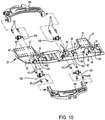
Figure 10 is an exploded view that shows a portion of the skid plate module and components associated with mounting lower control arms to the skid plate module. -
Figure 11 is a perspective view that shows first and second mounting bracket subassemblies. -
Figure 12 is an exploded view of the first mounting bracket subassembly. -
Figure 13 is a section view along section line 13-13. -
Figure 14 is an exploded view of the second mounting bracket subassembly. -
Figure 15 is a section view along section line 15-15. - As required, detailed embodiments of the present invention are disclosed herein; however, it is to be understood that the disclosed embodiments are merely exemplary of the invention that may be embodied in various and alternative forms. The figures are not necessarily to scale; some features may be exaggerated or minimized to show details of particular components. Therefore, specific structural and functional details disclosed herein are not to be interpreted as limiting, but merely as a representative basis for teaching one skilled in the art to variously employ the present invention.
- Referring to
Figure 1 , a portion of avehicle 10 is shown. Thevehicle 10 may be a motor vehicle like a truck, bus, farm equipment, military transport or weaponry vehicle, or cargo loading equipment for land, air, or marine vessels. Thevehicle 10 may include achassis 20, askid plate module 22, asuspension system 24, awheel end assembly 26, abrake subsystem 28, astabilizer bar subassembly 30, and atoe link 32. - Referring to
Figures 1 and3 , thechassis 20 may be the structural framework of thevehicle 10. In at least one configuration, thechassis 20 may include frame rails that may extend between the front and rear of thevehicle 10 and components such as cross rails that may interconnect the frame rails. Thechassis 20 may also facilitate mounting of thesuspension system 24 to thevehicle 10. Thechassis 20 may not include body panels of thevehicle 10, such as doors, fenders, hood, roof panel, or the like. Thechassis 20 is shown in phantom inFigures 1 and3 to allow other features of thevehicle 10 to be better illustrated. - Referring to
Figures 3 and9 , theskid plate module 22 may be configured to be mounted to thechassis 20. For example, theskid plate module 22 may be located underneath thechassis 20 and may be fixedly disposed on or fixedly mounted to thechassis 20. As such, theskid plate module 22 may extend along or may at least partially define the underside of thevehicle 10. In addition, theskid plate module 22 may facilitate mounting of thesuspension system 24 or a portion thereof as will be discussed in more detail below. Theskid plate module 22 may be a load carrying assembly that may help stiffen thechassis 20 and may help provide the structural framework of thevehicle 10. In at least one configuration, theskid plate module 22 may includeskid plate 40, and one ormore pillars 42. - The
skid plate 40 may be disposed at the bottom of theskid plate module 22. In addition, theskid plate 40 may be spaced apart from thechassis 20. Theskid plate 40 may help protect various components of thevehicle 10 from damage. For instance, theskid plate 40 may help protect one or more components of a vehicle drivetrain from damage, such as may be caused by "grounding out" or hitting an object under thevehicle 10, such as rocks, curbs, the road surface, or the like. Adrivetrain component 50 may be associated with propulsion of thevehicle 10. For example, adrivetrain component 50 may be a power source like a battery, engine, motor (including but not limited to an electric motor) or may be a torque transmission component like a transmission, gearbox, transfer case, axle assembly, differential, or the like. Theskid plate 40 may be made of any suitable material, such as a metal or metal alloy. In at least one configuration, theskid plate 40 may be substantially flat or planar and may include afirst end 60 and asecond end 62. - The
first end 60 of theskid plate 40 may be positioned closest to the front of thevehicle 10. - The
second end 62 of theskid plate 40 may be disposed opposite thefirst end 60. As such, thesecond end 62 of theskid plate 40 may be positioned closest to the rear of thevehicle 10. - Referring to
Figure 9 , acenter plane 64 may extend from thefirst end 60 to thesecond end 62. Thecenter plane 64 may extend vertically and may be disposed substantially perpendicular to theskid plate 40. In addition, thecenter plane 64 may be disposed along a center axis of thevehicle 10. Thecenter plane 64 may be disposed proximate the center of theskid plate module 22. For instance, thecenter plane 64 may bisect theskid plate 40 or one ormore pillars 42 such that theskid plate 40 or one ormore pillars 42 may have mirror symmetry with respect to thecenter plane 64. - Referring to
Figures 3 ,9 and10 , one ormore pillars 42 may extend from theskid plate 40 to thechassis 20. As such, apillar 42 may extend in a generally vertical direction from theskid plate 40 to thechassis 20. In the configuration shown, threepillars 42 are provided; however, it is contemplated that a greater or lesser number ofpillars 42 may be provided. For convenience in reference, the three pillars may be referred to as a first pillar, a second pillar, and a third pillar. The first pillar may be disposed at or closest to thefirst end 60 of theskid plate 40. The second pillar may be disposed rearward of the first pillar along thecenter plane 64 and may be located between the first pillar and the third pillar. The third pillar may be disposed at or closest to thesecond end 62 of theskid plate 40. Thepillars 42 may be spaced apart from each other and may be arranged along thecenter plane 64. In at least one configuration, apillar 42 may include a mountingplate 70, one or more mountingsleeves 72, one ormore recesses 74, and one ormore tubes 76. - A mounting
plate 70 may facilitate mounting of apillar 42 to thechassis 20. For example, a mountingplate 70 may be disposed at an opposite end of apillar 42 from theskid plate 40 and may be coupled to thechassis 20 in any suitable manner. For instance, the mountingplate 70 may be welded to thechassis 20 or may have a plurality of holes that may receive fasteners, such as bolts, rivets, or the like, that may attach the mountingplate 70 to thechassis 20. - Referring to
Figures 9 and10 , a mountingsleeve 72 may be provided with apillar 42 to facilitate mounting of a lower control arm as will be discussed in more detail below. In at least one configuration, a mountingsleeve 72 may be configured as a hollow cylindrical tube that may have a threaded hole that may be configured to receive afastener 80, such as bolt, that may couple a lower control arm to the mountingsleeve 72. The mountingsleeve 72 may be fixedly disposed on apillar 42 or fixedly positioned with respect to apillar 42. - A mounting
sleeve 72 may extend through apillar 42, such as from a firstlateral side 90 of apillar 42 to a secondlateral side 92 of thepillar 42. The firstlateral side 90 and the secondlateral side 92 may define opposing sides of thepillar 42 and may be disposed on opposite sides of thecenter plane 64. For instance, the firstlateral side 90 may face toward the left side of thevehicle 10 when viewed from a position in front of thevehicle 10 while the secondlateral side 92 may face toward the right side of thevehicle 10 when viewed from a position in front of thevehicle 10. Thecenter plane 64 may intersect and may bisect a mountingsleeve 72 that extends from a firstlateral side 90 to a secondlateral side 92. - One or more
mounting sleeves 72 may be provided with apillar 42. In the configuration shown inFigure 9 , a pair of mountingsleeves 72 is provided with the first pillar and the third pillar while four mounting sleeves are provided with the second pillar; however, it is contemplated that a greater or lesser number of mountingsleeves 72 may be provided. For instance, it is contemplated that separate spaced apart mounting sleeves may be provided with the firstlateral side 90 and the secondlateral side 92 of apillar 42 rather than providing mountingsleeves 72 that extend from the firstlateral side 90 to the secondlateral side 92. - Referring to
Figures 9 and10 , one ormore recesses 74 may be provided with apillar 42 to facilitate pivotal movement of alower control arm 254. For example, arecess 74 may be configured to partially receive at least onelower control arm 254 and may be sized to facilitate rotation or pivoting of thelower control arm 254 about an axis. In at least one configuration, arecess 74 may extend upward from theskid plate 40 and optionally may be partially defined by or bounded by theskid plate 40. In addition, arecess 74 may be positioned in a longitudinal direction or in a direction that extends along thecenter plane 64 between a pair of mountingsleeves 72. For instance, eachrecess 74 may be longitudinally centered between a pair of mountingsleeves 72 that may be disposed on opposite sides of therecess 74. - A
recess 74 may be provided in various configurations. For instance, arecess 74 may be configured as a through hole that may extend from the firstlateral side 90 to the secondlateral side 92 of apillar 42. Examples ofrecesses 74 having a through hole configuration is shown with the first pillar and with the recess located directly under the mountingplate 70 of the second pillar. In such a configuration, therecess 74 may partially receive two lower control arms, such as a firstlower control arm 254 that that may be disposed proximate the firstlateral side 90 and a secondlower control arm 254 that may be disposed proximate the secondlateral side 92. - Alternatively, a
recess 74 may not be configured as a through hole but instead may extend from a lateral side to an intervening feature or member, such as aweb 94. Examples ofrecesses 74 that are partially defined by aweb 94 are shown with the second pillar (to the left of its mounting plate 70) and with the third pillar, which is shown inFigure 9 . Aweb 94 may extend upward and away from theskid plate 40 and may effectively separate a through hole recess into separate opposing recesses. As such, arecess 74 may extend from the firstlateral side 90 of apillar 42 to theweb 94 while an opposingrecess 74 may extend from the secondlateral side 92 to theweb 94. In addition, theweb 94 may be disposed along thecenter plane 64. In such configurations, eachrecess 74 may partially receive differentlower control arms 254. - Referring to
Figures 10 and13 , atube 76 may be provided with apillar 42 to facilitate mounting of a mounting bracket assembly as will be discussed in more detail below. In at least one configuration, atube 76 may be configured as a hollow cylindrical tube that may be configured to receive a mounting bracket assembly that may couple adrivetrain component 50 to theskid plate module 22. Atube 76 may extend at least partially through apillar 42 and may be fixedly mounted on apillar 42 or fixedly positioned with respect to apillar 42. As is best shown inFigure 10 , atube 76 may be positioned above theskid plate 40 and may be located further from or further above theskid plate 40 than the mountingsleeves 72. As such, atube 76 may be located above a pivot axis of alower control arm 254 as will be discussed in more detail below. - One or
more tubes 76 may be provided with apillar 42. In the configuration shown inFigure 10 , onetube 76 is provided with the first pillar and the third pillar while twotubes 76 are provided with the second pillar; however, it is contemplated that a greater or lesser number oftubes 76 may be provided. For instance, it is contemplated that asingle tube 76 may be provided with the second pillar in a configuration where the third pillar may be omitted. - Referring to
Figures 10 and13 , thetube 76 may include a firsttube end surface 100, a secondtube end surface 102, atube hole 104, aninner tube surface 106, and an outer tube surface 108. - The first
tube end surface 100 may be disposed proximate the firstlateral side 90 of apillar 42. Optionally, the firsttube end surface 100 may protrude from the firstlateral side 90. - The second
tube end surface 102 may be disposed opposite the firsttube end surface 100. As such, the secondtube end surface 102 may be disposed proximate the secondlateral side 92 of thepillar 42. Optionally, the secondtube end surface 102 may protrude from the secondlateral side 92. - The
tube hole 104, which is best shown inFigure 10 , may extend from the firsttube end surface 100 to the secondtube end surface 102. Thetube hole 104 may be substantially cylindrical. - The
inner tube surface 106, which is best shown inFigure 13 , may extend from the firsttube end surface 100 to the secondtube end surface 102. Theinner tube surface 106 may define thetube hole 104. - The outer tube surface 108 may extend from the first
tube end surface 100 to the secondtube end surface 102. In addition, the outer tube surface 108 may be disposed opposite and may face away from thetube hole 104 and theinner tube surface 106. The outer tube surface 108 may engage thepillar 42 and may be fixedly coupled to thepillar 42. - Referring to
Figures 3 and9 , one or moremounting bracket subassemblies drivetrain component 50 to thechassis 20, theskid plate module 22, or both. In the configuration shown, four mounting bracket subassemblies are associated with eachdrivetrain component 50; however, it is contemplated that a greater or lesser number of mountingbracket subassemblies - Referring to
Figures 3 ,9 and11 , the mountingbracket subassemblies reference numbers bracket subassembly drivetrain component 50 to thechassis 20 or to theskid plate module 22 depending on the configuration of thedrivetrain component 50. As one nonlimiting example which is best shown with reference toFigures 3 and9 , two mountingbracket subassemblies 110 may couple thedrivetrain component 50 to thechassis 20, one mountingbracket subassembly 110 may couple thedrivetrain component 50 to apillar 42, and one mountingbracket subassembly 110' may couple thedrivetrain component 50 to anotherpillar 42. For convenience in reference, the mountingbracket subassembly 110 may also be referred to as a first mounting bracket subassembly to help distinguish from mountingbracket subassembly 110'. - Referring to
Figures 11-13 , the mountingbracket subassembly 110 is shown in more detail. The mountingbracket subassembly 110 may include arod 120, afirst sleeve 122, afirst bushing 124, afirst mounting plate 126, afirst nut 128, and one ormore fasteners 130. The mountingbracket subassembly 110 may also include asecond sleeve 132, asecond bushing 134, asecond mounting plate 136, and asecond nut 138. Optionally, the mountingbracket subassembly 110 may include one or more spacers, such as afirst spacer 140 and asecond spacer 142. - Referring primarily to
Figure 13 , therod 120 may be at least partially disposed in thetube 76 of apillar 42. For example, therod 120 may extend along arod axis 150 and main extend completely through thetube 76 such that the ends of therod 120 protrude from thetube 76. Referring toFigures 12 and13 , therod 120 may include a first threadedportion 160 and a second threadedportion 162. The first threadedportion 160 may extend from a first end of therod 120. The second threadedportion 162 may extend from a second end of therod 120 that may be disposed opposite the first end. Therod 120 may be substantially cylindrical between the first end and the second end. - The
first sleeve 122 may receive therod 120. Thefirst sleeve 122 may be made of a stiffer or less flexible material than thefirst bushing 124, such as a metal or metal alloy. In at least one configuration, thefirst sleeve 122 may include asleeve body 170, asleeve flange 172, and asleeve hole 174. - The
sleeve body 170 may have a hollow tubular or cylindrical configuration in one or more embodiments. Thesleeve body 170 may extend around therod 120 and may be at least partially disposed in thetube 76. In at least one configuration, thesleeve body 170 may have an innersleeve body surface 180, an outersleeve body surface 182, and asleeve end surface 184. - The inner
sleeve body surface 180 may extend from thesleeve flange 172 to thesleeve end surface 184. The innersleeve body surface 180 may face toward and may engage therod 120. - The outer
sleeve body surface 182 may extend from thesleeve flange 172 to thesleeve end surface 184. The outersleeve body surface 182 may be disposed opposite the innersleeve body surface 180 and may face away from therod 120. - The
sleeve end surface 184 may be disposed at an end of thesleeve body 170 that may be disposed opposite thesleeve flange 172. Thesleeve end surface 184 may extend from the innersleeve body surface 180 to the outersleeve body surface 182. - The
sleeve flange 172 may extend from an end of thesleeve body 170. For example, thesleeve flange 172 may extend from an end of thesleeve body 170 that may be disposed opposite thesleeve end surface 184 and may extend away from therod axis 150. Thesleeve flange 172 may be disposed substantially perpendicular to therod axis 150, the innersleeve body surface 180, the outersleeve body surface 182, or combinations thereof. In addition, thesleeve flange 172 may be disposed outside thetube 76. - The
sleeve hole 174 may be defined by thesleeve body 170 and thesleeve flange 172. For example, thesleeve hole 174 may be at least partially defined by the innersleeve body surface 180. Therod 120 may extend through thesleeve hole 174. - The
first bushing 124 may receive thefirst sleeve 122. Thefirst bushing 124 may be made of a more resilient or more compressible material than thefirst sleeve 122. For instance, thefirst bushing 124 may be made of rubber or a similar material. In at least one configuration, thefirst bushing 124 may include abushing body 190, abushing flange 192, and abushing hole 194. - The
bushing body 190 may have a hollow tubular or cylindrical configuration in one or more embodiments. Thebushing body 190 may extend around thesleeve body 170 and may be completely disposed in thetube 76. In at least one configuration, thebushing body 190 may have an innerbushing body surface 200, an outerbushing body surface 202, and abushing end surface 204. - The inner
bushing body surface 200 may extend from thebushing flange 192 to thebushing end surface 204. The innerbushing body surface 200 may face toward and may engage the outersleeve body surface 182. - The outer
bushing body surface 202 may extend from thebushing flange 192 to thebushing end surface 204. The outerbushing body surface 202 may be disposed opposite the innerbushing body surface 200 and may face toward and may engage theinner tube surface 106 of thetube 76. - The
bushing end surface 204 may be disposed at an end of thebushing body 190 that may be disposed opposite thebushing flange 192. Thebushing end surface 204 may extend from the innerbushing body surface 200 to the outerbushing body surface 202. - The
bushing flange 192 may extend from an end of thebushing body 190. For example, thebushing flange 192 may extend from an end of thebushing body 190 that may be disposed opposite thebushing end surface 204 and may extend away from therod 120 and therod axis 150. Thebushing flange 192 may extend substantially perpendicular to therod axis 150, the innerbushing body surface 200, the outerbushing body surface 202, or combinations thereof. In addition, thebushing flange 192 may be disposed outside thetube 76 and may be axially positioned or positioned along therod axis 150 between the firsttube end surface 100 and thesleeve flange 172. Moreover, thebushing flange 192 may engage or contact the firsttube end surface 100 and thesleeve flange 172. - The
bushing hole 194 may be defined by thebushing body 190 and thebushing flange 192. For example, thebushing hole 194 may be at least partially defined by the innerbushing body surface 200. Thesleeve body 170 may extend at least partially through thebushing hole 194. - The
first mounting plate 126 may extend from therod 120 and may be operatively connected to thedrivetrain component 50. Thefirst mounting plate 126 may be axially positioned between thefirst nut 128 and thefirst sleeve 122. Moreover, the first mountingplate 126 may be axially positioned between thefirst nut 128 and thefirst spacer 140, if provided. In at least one configuration, the first mountingplate 126 may include arod hole 210 and one or more fastener holes 212. Therod 120 may extend through therod hole 210. Afastener 130 may extend through thefastener hole 212. In the configuration shown, twofastener holes 212 are provided. - The
first nut 128 may help secure components of the mountingbracket subassembly 110. Thefirst nut 128 may engage a side of the first mountingplate 126 that may face away from thetube 76. Thefirst nut 128 may have a threaded hole that may receive and mate with the first threadedportion 160 of therod 120. Thefirst bushing 124 may be axially compressed against the firsttube end surface 100 of thetube 76 when thefirst nut 128 is tightened. More specifically, tightening thefirst nut 128 may exert pressure on the first mountingplate 126, thefirst spacer 140 if provided, thefirst sleeve 122, and thefirst bushing 124. This pressure may be resisted by thetube 76, which is fixed to theskid plate module 22. - One or
more fasteners 130 may be provided to attach the first mountingplate 126 to thedrivetrain component 50. Afastener 130 may be received in afastener hole 212 of the first mountingplate 126 and may extend to thedrivetrain component 50. Thefasteners 130 may have any suitable configuration. For instance, thefasteners 130 may have a similar configuration as therod 120 and may extend throughfastener holes 212 in the first mountingplate 126 and thesecond mounting plate 136. Alternatively, afastener 130 may be configured as a bolt and may extend through a single mounting plate to thedrivetrain component 50. - The
second sleeve 132 may have the same configuration as thefirst sleeve 122. Accordingly, thesecond sleeve 132 may receive therod 120 and may have the same features as thefirst sleeve 122. The features of thesecond sleeve 132 are referenced with the same reference numbers as the corresponding feature of thefirst sleeve 122. - The
second bushing 134 may have the same configuration as thefirst bushing 124. Accordingly, thesecond bushing 134 may receive thesecond sleeve 132, may be partially received in thetube 76, and may have the same features as thefirst bushing 124. The features of thesecond sleeve 132 are provided with the same reference numbers as the corresponding feature of thefirst sleeve 122. Thebushing flange 192 of thesecond bushing 134 may be disposed outside thetube 76 and may be axially positioned or positioned along therod axis 150 between the secondtube end surface 102 and thesleeve flange 172 of thesecond bushing 134. Moreover, thebushing flange 192 of thesecond bushing 134 may engage or contact the secondtube end surface 102 and thesleeve flange 172 of thesecond sleeve 132. Thesleeve body 170 of thesecond sleeve 132 may extend at least partially through thebushing hole 194 of thesecond bushing 134. - The
second mounting plate 136 may have the same configuration as the first mountingplate 126. Accordingly, thesecond mounting plate 136 may have the same features as the first mountingplate 126. The features of thesecond mounting plate 136 are provided with the same reference numbers as the corresponding feature of the first mountingplate 126. - The
second mounting plate 136 may be axially positioned between thesecond nut 138 and thesecond sleeve 132. Moreover, thesecond mounting plate 136 may be axially positioned between thesecond nut 138 and thesecond spacer 142, if provided. - The
second nut 138 may help secure components of the mountingbracket subassembly 110. Thesecond nut 138 may engage a side of thesecond mounting plate 136 that may face away from thetube 76. Thesecond nut 138 may have a threaded hole that may receive and mate with the second threadedportion 162 of therod 120. Thesecond bushing 134 may be axially compressed against the secondtube end surface 102 of thetube 76 when thesecond nut 138 is tightened. More specifically, tightening the 138 may exert pressure on thesecond mounting plate 136, thesecond spacer 142 if provided, thesecond sleeve 132, and thesecond bushing 134. This pressure may be resisted by thetube 76, which is fixed to theskid plate module 22. - The
first spacer 140, if provided, may receive therod 120. Thefirst spacer 140 may be made of a stiffer or less flexible material than thefirst bushing 124, such as a metal alloy or a polymeric material. In addition, thefirst spacer 140 may be axially positioned between thefirst sleeve 122 and the first mountingplate 126 and may extend from thefirst sleeve 122 to the first mountingplate 126. In at least one configuration, thefirst spacer 140 may include a firstspacer end surface 220, a secondspacer end surface 222, and aspacer hole 224. - The first
spacer end surface 220 may face toward and may engage the first mountingplate 126. - The second
spacer end surface 222 may be disposed opposite the firstspacer end surface 220. As such, the secondspacer end surface 222 may face toward and may engage thesleeve flange 172 of thefirst sleeve 122. The firstspacer end surface 220 and the secondspacer end surface 222 may be disposed substantially parallel to each other in one or more configurations. - The
spacer hole 224 may extend from the firstspacer end surface 220 to the secondspacer end surface 222. Thespacer hole 224 may receive therod 120 and therod 120 may engage thefirst spacer 140 in thespacer hole 224. - The
second spacer 142, if provided, may have the same configuration as thefirst spacer 140. Accordingly, thesecond spacer 142 may have the same features as thefirst spacer 140. The features of thesecond spacer 142 are provided with the same reference numbers as the corresponding feature of thefirst spacer 140. Thesecond spacer 142 may be axially positioned between thesecond sleeve 132 and thesecond mounting plate 136 and may extend from thesecond sleeve 132 to thesecond mounting plate 136. Accordingly, the firstspacer end surface 220 of thesecond spacer 142 may face toward an may engage thesecond mounting plate 136 while the secondspacer end surface 222 may face toward an may engage thesleeve flange 172 of thesecond sleeve 132. - The
first sleeve 122 and thesecond sleeve 132 may cooperate to limit axial compression of thefirst bushing 124 and thesecond bushing 134. For instance, thefirst sleeve 122 and thesecond sleeve 132 may be actuatable toward each other or actuatable along therod axis 150 when thesleeve end surface 184 of thefirst sleeve 122 is spaced apart from and does not engage thesleeve end surface 184 of thesecond sleeve 132. However, thefirst sleeve 122 and thesecond sleeve 132 are not actuatable toward each other when thesleeve end surface 184 of thefirst sleeve 122 contacts thesleeve end surface 184 of thesecond sleeve 132. As such, thefirst sleeve 122 and thesecond sleeve 132 may cooperate to prevent further axial compression of thefirst bushing 124 and thesecond bushing 134 when the sleeve end surfaces 184 contact each other. Thus, overtightening of thefirst nut 128 and thesecond nut 138 and potential damage to thefirst bushing 124 and thesecond bushing 134 may be prevented and thefirst sleeve 122 and thesecond sleeve 132 may cooperate to limit the axial load force or preload force that may be applied to thefirst bushing 124 and thesecond bushing 134. - Referring to
Figures 14 and15 , an alternative configuration of a mountingbracket subassembly 110' as shown. This configuration may be substantially similar to the mountingbracket subassembly 110 previously described but may include a modified first mounting plate 126', a modified second mounting plate 136', and the addition of a first extension plate 230' and a second extension plate 240'. - The first mounting plate 126' may extend from the
rod 120 to the first extension plate 230'. The first mounting plate 126' may be axially positioned between thefirst nut 128 and thefirst sleeve 122 and may be axially positioned between thefirst nut 128 and thefirst spacer 140, if provided. Thefirst mounting plate 126 may include arod hole 210 as previously described and one or more fastener holes 212'. Therod 120 may extend through therod hole 210. A fastener 130' such as a bolt may extend through the fastener hole 212' of the first mounting plate 126' to the first extension plate 230' - The first extension plate 230' may extend from the first mounting plate 126' and may be operatively connected to the
drivetrain component 50. The first extension plate 230' may include at least one fastener hole 232' that may receive a corresponding fastener 130' and at least one fastener hole 234' that may receive acorresponding fastener 130 that may couple the first extension plate 230' to thedrivetrain component 50. - The second mounting plate 136' may have the same configuration as the first mounting plate 126'. Accordingly, the second mounting plate 136' may have the same features as the first mounting plate 126'. The features of the second mounting plate 136' are provided with the same reference numbers as the corresponding feature of the first mounting plate 126'.
- The second extension plate 240' may have the same configuration as the first extension plate 230'. Accordingly, the second extension plate 240' may have the same features as the first extension plate 230'. The features of the second extension plate 240' are provided with the same reference numbers as the corresponding feature of the first extension plate 230'.
- The mounting
bracket subassembly 110' shown inFigures 14 and15 may be provided to accommodate situations where thefasteners 130 that are coupled to thedrivetrain component 50 may be inaccessible or difficult to access, such as may occur when the mounting locations for the first extension plate 230' and/or the second extension plate 240' are received in a recess or recesses in thedrivetrain component 50. For instance, the first extension plate 230' and the second extension plate 240' may be attached to thedrivetrain component 50 withcorresponding fasteners 130 before the first extension plate 230' and the second extension plate 240' are attached to the first mounting plate 126' and the second mounting plate 136', respectively. Then the first extension plate 230' and the second extension plate 240' may be attached to the first mounting plate 126' and the second mounting plate 136', respectively, with the fasteners 130'. - It is contemplated that
drivetrain components 50 and suspension system components may be assembled to theskid plate module 22 prior to assembly to thechassis 20. As such, theskid plate module 22 may be a modular subassembly that may help streamline or simplify assembly of the vehicle. - Referring to
Figures 1-3 , a plurality ofsuspension systems 24 are shown. Asuspension system 24 may connect one or morewheel end assemblies 26 to thechassis 20 and/or theskid plate module 22. In addition, thesuspension system 24 may dampen vibrations associated with vehicle travel, provide a desired level of ride quality, control vehicle ride height, or combinations thereof. Thesuspension system 24 may be an independent suspension system that may allow wheels to move up and down independently with respect to each other or without influence from another wheel.Figures 4-8 show a portion of asuspension system 24 that is associated with a single wheel; however, is it to be understood that thesuspension system 24 may be associated with multiple wheels. For instance, the components of thesuspension system 24 that are shown inFigures 4-8 may be provided with a wheel like a right side wheel when viewed from a position in front of the vehicle. These components may also be provided as a mirror image when provided with an opposing wheel like a left side wheel. In at least one configuration, thesuspension system 24 may include aknuckle 250, anupper control arm 252, alower control arm 254, afirst air spring 256, asecond air spring 258, and ashock absorber 260. - Referring to
Figures 4-8 , theknuckle 250 may rotatably support thewheel end assembly 26. In addition, theknuckle 250 may interconnect thewheel end assembly 26 to theupper control arm 252 and thelower control arm 254. As is best shown inFigures 7 and8 , theknuckle 250 may include a knuckle body 270 and aspindle 272. - The knuckle body 270 may facilitate mounting of various components to the
knuckle 250. In at least one configuration, the knuckle body 270 may be configured as a unitary one-piece component, although it is contemplated that the knuckle body 270 could be an assembly of multiple components. The knuckle body 270 may include an uppercontrol arm mount 280, a lowercontrol arm mount 282, afirst platform 284, asecond platform 286, aspindle mount 288, and abrake torque plate 290. - The upper
control arm mount 280 may be disposed near the top of the knuckle body 270. In addition, the uppercontrol arm mount 280 may be longitudinally positioned between or disposed between thefirst platform 284 and thesecond platform 286. In at least one configuration, the uppercontrol arm mount 280 may have a first mountinghole 300 and asecond mounting hole 302 that may facilitate mounting of theupper control arm 252. Thefirst mounting hole 300 and thesecond mounting hole 302 may each receive a fastener, such as a bolt, that may couple a pivot mechanism to the uppercontrol arm mount 280. The pivot mechanism may facilitate rotation of theupper control arm 252 with respect to theknuckle 250 as will be discussed in more detail below. - The lower
control arm mount 282 may be disposed near or at the bottom of the knuckle body 270. The lowercontrol arm mount 282 may have any suitable configuration. For instance, the lowercontrol arm mount 282 may be configured as an opening or aperture that may extend from afirst side 310 of the knuckle body 270 to asecond side 312 of the knuckle body 270. Thefirst side 310 may face toward the front of thevehicle 10. Thesecond side 312 may be disposed opposite thefirst side 310 and may face toward the rear of thevehicle 10. The lowercontrol arm mount 282 may receive a pivot mechanism that may pivotally couple thelower control arm 254 to the knuckle body 270. - The
first platform 284 may be disposed near the top of the knuckle body 270 and may be configured to support thefirst air spring 256. Thefirst platform 284 may extend in a longitudinal direction that may extend away from the uppercontrol arm mount 280 and toward the front of thevehicle 10. In addition, thefirst platform 284 may extend in a lateral direction that may extend away from thewheel end assembly 26 and toward thechassis 20 and thecenter plane 64. In at least one configuration, thefirst platform 284 may include atop side 320, abottom side 322, afirst side 324, asecond side 326, and atoe link mount 328. - The
top side 320 may face upward toward thefirst air spring 256. In addition, thetop side 320 may engage thefirst air spring 256. - The
bottom side 322 may be disposed opposite thetop side 320. As such, thebottom side 322 may face away from thefirst air spring 256. In at least one configuration, thebottom side 322 may include arecess 330, which is best shown inFigure 6 . - The
recess 330 may help provide clearance to thetoe link 32 throughout its range of motion and the range of travel of theknuckle 250. Therecess 330 may extend from thebottom side 322 toward thetop side 320. In addition, therecess 330 may extend longitudinally from thesecond side 326 in a rearward direction toward the uppercontrol arm mount 280 and thesecond platform 286. - The
first side 324 may extend from thetop side 320 to thebottom side 322. Thefirst side 324 may face toward thewheel end assembly 26. - The
second side 326 or portion thereof may extend from thetop side 320 to thebottom side 322. Thesecond side 326 may face toward the front of thevehicle 10 and may face away from thesecond platform 286. - The
toe link mount 328 may extend from thefirst platform 284. Moreover, thetoe link mount 328 may be integrally formed with thefirst platform 284. Thetoe link mount 328 may extend from thefirst platform 284 in multiple directions. For example, thetoe link mount 328 may extend vertically such that thetoe link mount 328 may extend above thetop side 320 and below thebottom side 322 of thefirst platform 284. In addition, thetoe link mount 328 may extend from thefirst side 324 to thesecond side 326. As such, thetoe link mount 328 may extend away from thesecond platform 286 and protrude toward the front of thevehicle 10 and may protrude laterally away from thecenter plane 64. - The
toe link mount 328 may have a toelink mounting hole 340. The toelink mounting hole 340 may extend along a toe link mountinghole axis 342. As such, the toelink mounting hole 340 may receive thetoe link 32 and permit thetoe link 32 to pivot with respect to the toe link mountinghole axis 342. The toe link mountinghole axis 342 may be disposed in a nonparallel and non-perpendicular relationship with thetop side 320,bottom side 322,first side 324,second side 326, or combinations thereof. Thetoe link mount 328 may be spaced apart from other features of theknuckle 250. - The
second platform 286 may be disposed near the top of the knuckle body 270 and may be configured to support thesecond air spring 258. Thesecond platform 286 may be spaced apart from thefirst platform 284. Moreover, thesecond platform 286 may be disposed on an opposite side of the uppercontrol arm mount 280 with respect to thefirst platform 284. As such, theupper control arm 252 may be positioned between thefirst platform 284 and thesecond platform 286 and thesecond platform 286 may extend in a longitudinal direction that may extend away from thefirst platform 284 and toward the rear of thevehicle 10. In addition, thesecond platform 286 may extend in a lateral direction that may extend away from thewheel end assembly 26 and toward thechassis 20 and thecenter plane 64. In at least one configuration, thesecond platform 286 may include atop side 350, abottom side 352, afirst side 354, asecond side 356, and astabilizer bar mount 358. - The
top side 350 may face upward toward thesecond air spring 258. In addition, thetop side 350 may engage thesecond air spring 258. - The
bottom side 352 may be disposed opposite thetop side 350. As such, thebottom side 352 may face away from thesecond air spring 258. - The
first side 354 may extend from thetop side 350 to thebottom side 352. Thefirst side 354 may face toward thewheel end assembly 26. - The
second side 356 may extend from thetop side 350 to thebottom side 352. Thesecond side 356 may face toward the rear of thevehicle 10 and may face away from thefirst platform 284. In addition, thesecond side 356 may extend from an end of thefirst side 354. - The
stabilizer bar mount 358 may extend from thesecond platform 286. Moreover, thestabilizer bar mount 358 may be integrally formed with thesecond platform 286. Thestabilizer bar mount 358 may extend from thefirst platform 284 in a downward vertical direction such that thestabilizer bar mount 358 extends from thebottom side 352 in a direction that extends away from thesecond air spring 258 and thetop side 350. In addition, thestabilizer bar mount 358 may extend from thefirst side 354 and thesecond side 356 and may have sides or surfaces that may be aligned with or may be coplanar with thefirst side 354 and thesecond side 356. As such, thestabilizer bar mount 358 may generally be positioned at a rear outboard corner of thesecond platform 286. Thestabilizer bar mount 358 may be spaced apart from other features of theknuckle 250. - The
stabilizer bar mount 358 may have a stabilizerbar mount hole 360 that may receive thestabilizer bar subassembly 30. The stabilizerbar mount hole 360 may be disposed substantially perpendicular to thecenter plane 64. - Referring to
Figures 7 and8 , thespindle mount 288 may be positioned below the uppercontrol arm mount 280 and above the lowercontrol arm mount 282. Thespindle mount 288 may facilitate mounting of thespindle 272. For example, thespindle mount 288 may have a hollow tubular configuration that may be centered about aspindle mount axis 370 and may protrude from the knuckle body 270 toward thewheel end assembly 26. Thespindle mount axis 370 may also an axis of rotation of a wheel. As is best shown inFigure 7 , thespindle mount 288 and thespindle mount axis 370 may be longitudinally offset from the center of the uppercontrol arm mount 280, the lowercontrol arm mount 282, and thebrake torque plate 290. For example, thespindle mount axis 370 may be disposed further rearward than acenter plane 372 of the uppercontrol arm mount 280, acenter plane 374 of the lowercontrol arm mount 282, and thebrake torque plate 290. Thecenter plane 372 of the uppercontrol arm mount 280 may be disposed perpendicular to thecenter plane 64 of theskid plate module 22 and may be positioned at the longitudinal center of the uppercontrol arm mount 280. Thecenter plane 374 of the lowercontrol arm mount 282 may be disposed perpendicular to thecenter plane 64 and may be positioned at the longitudinal center of the lowercontrol arm mount 282. - Referring primarily to
Figures 7 and8 , thebrake torque plate 290 may facilitate mounting of thebrake subsystem 28. In addition, thebrake torque plate 290 may facilitate mounting of anantilock brake sensor 380. In at least one configuration, thebrake torque plate 290 may extend from thespindle mount 288 and may include anupper portion 390, alower portion 392, afront side 394, and arear side 396. - The
upper portion 390 may extend from thespindle mount 288 toward the uppercontrol arm mount 280. Theantilock brake sensor 380 may be mounted to theupper portion 390. - The
lower portion 392 may be disposed opposite theupper portion 390 or on an opposite side of thespindle mount 288 from theupper portion 390. As such, thelower portion 392 may extend from thespindle mount 288 toward the lowercontrol arm mount 282. Thelower portion 392 may be aligned with theupper portion 390. As is best shown inFigure 8 , thelower portion 392 may be aligned with and may partially define thesecond side 312 of the lowercontrol arm mount 282. - Referring to
Figure 8 , theupper portion 390 and thelower portion 392 may include one or morebrake mounting holes 400. Thebrake mounting holes 400 may receivefasteners 402, such as bolts, that may facilitate mounting of thebrake subsystem 28 to thebrake torque plate 290. For example, thebrake subsystem 28 may be disposed on and may engage thefront side 394 of theupper portion 390 in thelower portion 392. Thefront side 394 may face toward the front of thevehicle 10 or toward thefirst platform 284. Therear side 396 may be disposed opposite thefront side 394 and may face toward the rear of thevehicle 10 or toward thesecond platform 286. - Referring to
Figure 7 , theupper portion 390 and thelower portion 392 may be aligned with each other and may be disposed in a common plane. For example, theupper portion 390 and thelower portion 392 may be disposed in a braketorque plate plane 410 or may be centered with respect to a braketorque plate plane 410. The braketorque plate plane 410 may be disposed substantially perpendicular to thecenter plane 64. As such, the braketorque plate plane 410 may extend in a lateral vehicle direction. The braketorque plate plane 410 may be longitudinally positioned between the first mountinghole 300 and thesecond mounting hole 302 of the uppercontrol arm mount 280 such that the braketorque plate plane 410 may be disposed closer to the first mountinghole 300 than thesecond mounting hole 302. In addition, the braketorque plate plane 410 may be disposed parallel to and may be positioned between thecenter plane 372 of the uppercontrol arm mount 280 and thecenter plane 374 of the lowercontrol arm mount 282. - In addition, the
spindle mount axis 370 may be disposed parallel to the braketorque plate plane 410. Thespindle mount axis 370 may be offset from the braketorque plate plane 410 such that thespindle mount axis 370 may be disposed further rearward than thecenter plane 372 of the uppercontrol arm mount 280, thecenter plane 374 of the lowercontrol arm mount 282 and the braketorque plate plane 410. As such, thespindle mount axis 370 may not intersect the braketorque plate plane 410. - Referring to
Figure 8 , thespindle 272 may extend from thespindle mount 288. For example, thespindle 272 may be received in thespindle mount 288 and may be fixedly attached to thespindle mount 288 in any suitable manner, such as with an interference fit, welding, or with one or more fasteners. It is also contemplated that thespindle 272 may be integrally formed with the knuckle body 270 such that thespindle 272 and the knuckle body 270 are not separate components. Thespindle 272 may rotatably support thewheel end assembly 26. For example, thespindle 272 may support one or more wheel bearings that rotatably support a hub as will be discussed in more detail below. Thespindle 272 may extend along or around thespindle mount axis 370. In addition, thespindle 272 may be disposed between theupper portion 390 and thelower portion 392 of thespindle mount 288 in one or more configurations. - Referring to
Figures 1 and6 , theupper control arm 252 may extend from a lateral side of thechassis 20 toward theknuckle 250. Theupper control arm 252 may be pivotally or rotatably mounted to thechassis 20 and theknuckle 250 in a manner that allows theknuckle 250 and a correspondingwheel end assembly 26 to move up and down while inhibiting forward and backward movement. As is best shown with reference toFigure 5 , theupper control arm 252 may have a Y-shaped configuration and may include afirst mounting arm 420, asecond mounting arm 422, and acenter arm 424. - The
first mounting arm 420 and thesecond mounting arm 422 may be pivotally coupled or rotatably coupled to thechassis 20. For instance, the first mountingarm 420 and thesecond mounting arm 422 may rotate about a common axis. In at least one configuration, the first mountingarm 420 and thesecond mounting arm 422 may each have an aperture that may be disposed proximate a distal end. Each aperture may receive apivot mechanism 426 that may pivotally couple the mounting arm to thechassis 20. Thepivot mechanism 426 may have any suitable configuration. For example, thepivot mechanism 426 may include a pivot pin that may extend through the aperture. The pivot pin may be fixedly coupled to thechassis 20 in any suitable manner, such as with one or more fasteners like bolts. - Referring to
Figures 5 and7 , thecenter arm 424 may be disposed between the first mountingarm 420 and thesecond mounting arm 422. Thecenter arm 424 may be pivotally coupled or rotatably coupled to theknuckle 250. For instance, thecenter arm 424 may rotate about an upper controlarm mount axis 430 that may be disposed perpendicular to the braketorque plate plane 410. In at least one configuration, thecenter arm 424 may include an aperture that may receive apivot mechanism 432 that may pivotally couple thecenter arm 424 to theknuckle 250. For example, thepivot mechanism 432 may include a pivot pin that may extend through the aperture. The pivot pin may be fixedly coupled to theknuckle 250 in any suitable manner, such as with one or more fasteners like bolts. A portion of thecenter arm 424 may be longitudinally positioned between thefirst air spring 256 and thesecond air spring 258. - Referring to
Figure 6 , thelower control arm 254 may be disposed below theupper control arm 252. Thelower control arm 254 may extend from a lateral side of theskid plate module 22 toward theknuckle 250. Thelower control arm 254 may be pivotally or rotatably mounted to theskid plate module 22 and theknuckle 250 in a manner that allows theknuckle 250 and a correspondingwheel end assembly 26 to move up and down while inhibiting forward and backward movement. Thelower control arm 254 may have a different configuration than theupper control arm 252. - Referring to
Figures 6 and10 , alower control arm 254 may pivotally mounted to one ormore pillars 42 with corresponding pivot mechanisms. For instance, onepivot mechanism 432 may pivotally connect alower control arm 254 to the mountingsleeves 72 of onepillar 42 while anotherpivot mechanism 432 may pivotally connect alower control arm 254 to the mountingsleeves 72 of anotherpillar 42. Alower control arm 254 may be pivotally mounted to the first pillar and the second pillar along a lower controlarm pivot axis 440 while anotherlower control arm 254 may be pivotally mounted to the second pillar and the third pillar along the same axis. The lower controlarm pivot axis 440 may be positioned closer to theskid plate 40 than thetubes 76. Thelower control arm 254 may also be pivotally mounted to theknuckle 250 along a lower controlarm mount axis 442 that may be disposed perpendicular to the braketorque plate plane 410. - An
upper control arm 252 and alower control arm 254 may be associated with eachwheel end assembly 26. As such,upper control arms 252 andlower control arms 254 may extend from opposite sides of thechassis 20 in theskid plate module 22 to support differentwheel end assemblies 26. - Referring to
Figures 1-4 , thefirst air spring 256 and thesecond air spring 258 may help dampen vibrations, provide a desired level of ride quality, and control ride height or the distance between the chassis and the road or support surface upon which a tire of thevehicle 10 is disposed. - Referring to
Figures 6-8 , thefirst air spring 256 may be fixedly disposed on thefirst platform 284. For example, thefirst air spring 256 may extend from thefirst platform 284 to thechassis 20. Thefirst air spring 256 may have any suitable configuration. For instance, thefirst air spring 256 may have a flexible bellows and a piston. The flexible bellows may at least partially define a chamber within thefirst air spring 256 that may receive the piston and pressurized gas that may be provided by a pressurized gas supply system. Pressurized gas may be provided to the chamber or may be vented from the chamber to adjust the ride height and dampening characteristics of the suspension system. An upper mounting plate may be provided at the top of the flexible bellows to facilitate mounting of the flexible bellows to thechassis 20. The piston may be at least partially received in the flexible bellows and may extend from thefirst platform 284 toward the upper mounting plate. For example, the piston may be fixedly disposed on thefirst platform 284, such as with one or more fasteners, and may be generally disposed near the center of the flexible bellows. - The
second air spring 258 may have a similar configuration or the same configuration as thefirst air spring 256. Thesecond air spring 258 may be fixedly disposed on thesecond platform 286. For example,second air spring 258 may extend from thesecond platform 286 to thechassis 20. As such, thefirst air spring 256 and thesecond air spring 258 may be disposed on opposite sides of theupper control arm 252. - Referring to
Figures 4-7 , theshock absorber 260, which may also be referred to as a strut, may extend from thechassis 20 to theknuckle 250. For example, theshock absorber 260 may be pivotally mounted to thechassis 20 at a first end and may be pivotally mounted to thelower control arm 254 at a second end. - Referring to
Figures 4-8 , thewheel end assembly 26 may facilitate rotation a wheel that may support a tire. Thewheel end assembly 26 may be part of a drive axle or a non-drive axle. A drive axle may receive torque from a power source, such as an engine or motor as previously discussed. In a drive axle configuration, ashaft 450, which is best shown inFigure 8 , such as an axle shaft or half shaft, may transmit torque to thewheel end assembly 26 to rotate a wheel that may be mounted on thewheel end assembly 26. For instance, theshaft 450 may be operatively connected at a first end to adrivetrain component 50 and may extend through thespindle 272 and be coupled to thewheel end assembly 26 at a second end. The shaft may be omitted in a non-drive axle configuration. In at least one configuration, thewheel end assembly 26 may include ahub 460. - The
hub 460 may be rotatably disposed on thespindle 272. For example, one or more wheel bearings may be disposed on thespindle 272 and may rotatably support thehub 460. Thehub 460 may facilitate mounting of the wheel, such as with a plurality of mountingstuds 462. As such, thehub 460 and the wheel may rotate together about thespindle mount axis 370. A tire may be disposed on the wheel that may engage a road or support surface. - The
brake subsystem 28 may facilitate braking of the wheel to slow rotation of thehub 460 and an associated wheel about thespindle mount axis 370. Thebrake subsystem 28 may have any suitable configuration. For instance, thebrake subsystem 28 may be configured as a friction brake, such as a disc brake or a drum brake. In the figures, thebrake subsystem 28 is depicted as a disc brake. In such a configuration, abrake friction member 470 configured as a brake rotor may be fixedly coupled to thehub 460 and may rotate with thehub 460. One or more brake pads may be actuated into engagement with thebrake friction member 470 to slow rotation of thehub 460 and the wheel about thespindle mount axis 370. - Referring to
Figures 1-3 , thestabilizer bar subassembly 30 may help reduce body roll or side-to-side rolling of thevehicle 10, such as may occur during cornering. Thestabilizer bar subassembly 30 may operatively connect opposingknuckles 250 of thevehicle 10. For example, thestabilizer bar subassembly 30 may be coupled tostabilizer bar mount 358 of thesecond platform 286. As is best shown with reference toFigures 3 and5-8 , thestabilizer bar subassembly 30 may include a pair ofdrop links 480, a pair ofintermediate links 482, and astabilizer bar 484. Onedrop link 480 may extend from thestabilizer bar mount 358 to a first end of anintermediate link 482. A second end of theintermediate link 482 may be coupled to a first end of thestabilizer bar 484. A mirror image arrangement of thedrop link 480 andintermediate link 482 may be provided with an opposingknuckle 250. For instance, anotherdrop link 480 may extend from thestabilizer bar mount 358 of asecond platform 286 that is provided with an opposingknuckle 250 to a first end of anotherintermediate link 482, which in turn may extend to a second end of thestabilizer bar 484 that may be disposed opposite the first end. The drop links 480 may extend in a downward direction that may extend toward thelower control arm 254. Theintermediate links 482 may extend in a rearward direction. - While exemplary embodiments are described above, it is not intended that these embodiments describe all possible forms of the invention. Rather, the words used in the specification are words of description rather than limitation, and it is understood that various changes may be made without departing from the spirit and scope of the invention. Additionally, the features of various implementing embodiments may be combined to form further embodiments of the invention.
Claims (15)
- An assembly comprising:a skid plate module that includes:a skid plate; andfirst and second pillars that extend from the skid plate and are adapted to be mounted to a chassis, wherein the first and second pillars are disposed along a center plane of the skid plate; andfirst and second lower control arms that are mounted to the first and second pillars, respectively.
- The assembly of claim 1 wherein the skid plate has a first end and a second end disposed opposite the first end and the first pillar is disposed at the first end.
- The assembly of claim 2 wherein the second pillar is disposed between the first end and the second end.
- The assembly of any preceding claim wherein the first pillar has a pair of mounting sleeves that extend through the first pillar and the first and second lower control arms are mounted to the pair of mounting sleeves, preferably the center plane intersects the pair of mounting sleeves.
- The assembly of any preceding claim wherein the first pillar has a first recess that partially receives the first lower control arm, preferably the first recess extends through the first pillar and partially receives the first and second lower control arms.
- The assembly of any preceding claim wherein the first pillar has a first tube that receives a first mounting bracket subassembly that mounts a drivetrain component to the skid plate module, preferably the first lower control arm is pivotally mounted to the first pillar and the second pillar along a lower control arm pivot axis and the lower control arm pivot axis is positioned closer to the skid plate than the first tube.
- The assembly of any preceding claim including first and second mounting bracket subassemblies that are mounted to the first and second pillars, respectively, for mounting a drivetrain component.
- The assembly of claim 7 wherein the first pillar has a first tube that extends at least partially through the first pillar and at least partially receives the first mounting bracket subassembly.
- The assembly of claim 8 wherein the first mounting bracket subassembly includes a rod that is disposed in the first tube, a first sleeve that receives the rod, a first bushing that receives the first sleeve and is received in the first tube, and a first mounting plate that extends from the rod and is operatively connected to the drivetrain component, preferably the rod extends completely through the first tube.
- The assembly of claim 9 wherein the first bushing has a first bushing flange that extends away from the rod and is disposed outside of the first tube such that the first bushing flange engages a first tube end surface of the first tube.
- The assembly of claim 10 wherein the first sleeve has a first sleeve flange that extends away from the rod and is disposed outside the first tube such that the first sleeve flange engages the first bushing flange and the first bushing flange is axially positioned between the first tube and the first sleeve flange, preferably the first mounting bracket subassembly has a first spacer that receives the rod and extends from the first sleeve to the first mounting plate.
- The assembly of claim 10 or claim 11 wherein the first mounting bracket subassembly has a first nut that receives the rod and the first bushing is axially compressed against the first tube end surface of the first tube when the first nut is tightened.
- The assembly of any one of claims 9 to 12 wherein the first mounting bracket subassembly has a second sleeve that receives the rod, a second bushing that receives the second sleeve and is received in the first tube, a second mounting plate that extends from the rod and is operatively connected to the drivetrain component, and a second nut that receives the rod, wherein the second bushing is axially compressed against a second tube end surface of the first tube when the second nut is tightened.
- The assembly of claim 13 wherein an end of the first sleeve engages an end of the second sleeve to limit axial compression of the first bushing and the second bushing.
- The assembly of any one of claims 9 to 14 wherein the at least one of the first and second mounting bracket subassemblies further comprises an extension plate that is fixedly disposed on the first mounting plate and extends from the first mounting plate to the drivetrain component.
Applications Claiming Priority (1)
| Application Number | Priority Date | Filing Date | Title |
|---|---|---|---|
| US16/291,462 US10814917B2 (en) | 2019-03-04 | 2019-03-04 | Assembly having a skid plate module |
Publications (2)
| Publication Number | Publication Date |
|---|---|
| EP3708467A1 true EP3708467A1 (en) | 2020-09-16 |
| EP3708467B1 EP3708467B1 (en) | 2022-11-30 |
Family
ID=69742958
Family Applications (1)
| Application Number | Title | Priority Date | Filing Date |
|---|---|---|---|
| EP20160107.7A Active EP3708467B1 (en) | 2019-03-04 | 2020-02-28 | Assembly having a skid plate module |
Country Status (2)
| Country | Link |
|---|---|
| US (1) | US10814917B2 (en) |
| EP (1) | EP3708467B1 (en) |
Families Citing this family (6)
| Publication number | Priority date | Publication date | Assignee | Title |
|---|---|---|---|---|
| USD924338S1 (en) * | 2019-06-27 | 2021-07-06 | Traxxas Lp | Model vehicle skid pad assembly |
| USD1014650S1 (en) | 2020-04-02 | 2024-02-13 | Traxxas, L.P. | Model vehicle roof skid |
| USD1014652S1 (en) | 2021-11-16 | 2024-02-13 | Traxxas, L.P. | Model vehicle skid pad |
| USD1016180S1 (en) | 2021-11-16 | 2024-02-27 | Traxxas, L.P. | Model vehicle lower skid pad |
| USD1017722S1 (en) * | 2021-11-16 | 2024-03-12 | Traxxas, L.P. | Model vehicle skid pad |
| USD1020927S1 (en) | 2022-03-04 | 2024-04-02 | Traxxas, L.P. | Model vehicle lighted roof skid assembly |
Citations (4)
| Publication number | Priority date | Publication date | Assignee | Title |
|---|---|---|---|---|
| US7114732B1 (en) * | 2003-11-21 | 2006-10-03 | Jeffery A Ismail | All-terrain welding cart |
| WO2011041549A2 (en) * | 2009-10-01 | 2011-04-07 | Oshkosh Corporation | Axle assembly |
| US20120181100A1 (en) * | 2008-12-29 | 2012-07-19 | Halliday Donald R | Deformable Modular Armored Combat System |
| US20170320365A1 (en) | 2016-05-06 | 2017-11-09 | Arvinmeritor Technology, Llc | Suspension Module Having an Air Spring Pedestal |
Family Cites Families (73)
| Publication number | Priority date | Publication date | Assignee | Title |
|---|---|---|---|---|
| US2866651A (en) | 1956-06-29 | 1958-12-30 | Charles L Powell | Vehicle wheel suspension means |
| DE1057469B (en) * | 1956-09-19 | 1959-05-14 | Daimler Benz Ag | Air suspension, especially for heavy-duty vehicles or the like. |
| US2971772A (en) * | 1959-03-18 | 1961-02-14 | Fruehauf Trailer Co | Wheel suspension and cantilever spring bracing therefor for trailer |
| US3007716A (en) * | 1960-08-18 | 1961-11-07 | Youngstown Steel Car Corp | Air cell supported road vehicle frame |
| US3477738A (en) | 1968-01-16 | 1969-11-11 | Gen Motors Corp | Auxiliary road wheel assembly |
| US4174855A (en) | 1977-01-13 | 1979-11-20 | Turner Quick-Lift Corporation | Wheeled vehicle axle suspension system |
| JPS54131210A (en) | 1978-04-03 | 1979-10-12 | Kawasaki Heavy Ind Ltd | Device for suspending guide track car |
| DE2918605A1 (en) | 1979-05-09 | 1980-11-13 | Daimler Benz Ag | SINGLE WHEEL SUSPENSION BY MEANS OF LEADERS |
| DE3136305A1 (en) | 1981-09-12 | 1983-03-24 | Hermann Dr.-Ing. 7412 Eningen Klaue | Drive axle for heavy motor vehicles |
| DE3734212A1 (en) | 1986-12-10 | 1989-04-20 | Sterki Ag | AXIS |
| US4813704A (en) * | 1988-06-20 | 1989-03-21 | Chrysler Motors Corporation | Dual strut wheel suspension |
| US5396968A (en) | 1992-03-18 | 1995-03-14 | Aisin Aw Co., Ltd. | Drive mechanism for electric car |
| JP3122728B2 (en) | 1992-04-28 | 2001-01-09 | 本田技研工業株式会社 | Automotive wheel suspension |
| US5413462A (en) | 1994-03-08 | 1995-05-09 | Reliance Electric Industrial Co. | Mechanical power transmission system having improved lubricant circulation apparatus |
| NL1000342C2 (en) | 1995-05-11 | 1996-11-12 | Weweler Nv | Air suspension system. |
| DE19619321C2 (en) | 1996-05-14 | 1998-07-09 | Voith Turbo Kg | Method for operating a vehicle with several electric drive machines |
| FR2752778B1 (en) | 1996-08-27 | 1998-10-09 | Smh Management Services Ag | TANDEM DRIVE UNIT WITH REDUCERS AND ELECTRIC OR HYBRID DRIVE VEHICLE COMPRISING SUCH A GROUP |
| JPH10324126A (en) | 1997-05-26 | 1998-12-08 | Isuzu Motors Ltd | Vehicular suspension device |
| WO1999022979A1 (en) | 1997-10-31 | 1999-05-14 | Constant Velocity | Independent rear suspension system |
| NL1008060C2 (en) | 1998-01-19 | 1999-07-20 | Stichting Platform Hoogwaardig | Vehicle, in particular an electrically powered vehicle. |
| DE19860230A1 (en) | 1998-12-24 | 2000-02-17 | Daimler Chrysler Ag | Multiaxis motor such as utility vehicle has wheel members and wheel carriers constructed from similar parts |
| JP4093515B2 (en) | 1999-05-12 | 2008-06-04 | 本田技研工業株式会社 | Front and rear wheel drive vehicle |
| SE516470C2 (en) | 1999-09-29 | 2002-01-15 | Scania Cv Ab | Front axle assembly for a heavy vehicle |
| WO2001051300A1 (en) | 2000-01-11 | 2001-07-19 | Bridgestone/Firestone, Inc. | Pneumatic suspension system for vehicles |
| US6840525B1 (en) | 2000-03-14 | 2005-01-11 | Meritor Heavy Vehicle Systems Limited | Air spring and pedestal |
| US6428027B1 (en) | 2000-05-22 | 2002-08-06 | The Boler Company | Front axle air suspension |
| US6866295B2 (en) | 2000-12-28 | 2005-03-15 | Dana Corporation | Modular cast independent front suspension subframe |
| US6695351B2 (en) | 2001-05-02 | 2004-02-24 | Meritor Heavy Vehicle Technology, Llc | Internal bulkhead for spring seat reinforcement |
| US6743135B2 (en) | 2001-09-28 | 2004-06-01 | General Motors Corporation | Modularly-constructed vehicular transmissions |
| US20030098564A1 (en) | 2001-11-29 | 2003-05-29 | Vandenberg Ervin | Independent suspension system for light and medium duty vehicles |
| US6752410B2 (en) | 2001-12-28 | 2004-06-22 | Meritor Heavy Vehicle Technology, Llc | Independent suspension for low profile vehicles |
| US7484744B2 (en) | 2002-02-01 | 2009-02-03 | Saf-Holland, Inc. | Trailing arm suspension with optimized I-beam |
| US20040150142A1 (en) | 2003-02-05 | 2004-08-05 | Warinner Derek K. | Steering beam axle air spring suspension |
| WO2004106110A1 (en) | 2003-06-03 | 2004-12-09 | Gemco Mobile Systems B.V. | Wheel suspension and vehicle |
| BRPI0405014A (en) | 2004-11-16 | 2006-06-27 | Jorge Antonio Rodrigues Claro | suspension for vehicles |
| US7472914B2 (en) * | 2005-02-28 | 2009-01-06 | Anderson Brian K | Suspension system |
| US20060208447A1 (en) | 2005-03-21 | 2006-09-21 | Arvinmeritor Technology, Llc | Independent suspension for a drive axle |
| DE102005019489A1 (en) | 2005-04-27 | 2006-11-09 | Krauss-Maffei Wegmann Gmbh & Co. Kg | Four-wheel drive motor vehicle |
| US8029008B2 (en) * | 2005-04-27 | 2011-10-04 | Hendrickson Usa, L.L.C. | Vehicle suspensions having leaf springs and alternative clamp groups |
| US7819411B2 (en) | 2005-05-20 | 2010-10-26 | Arvinmeritor Technology, Llc | Six link independent suspension for a drive axle |
| EP2026988A2 (en) | 2006-04-03 | 2009-02-25 | BluWav Systems, LLC | Vehicle power unit designed as retrofittable axle comprising motor, battery and suspension |
| US7384357B2 (en) | 2006-05-05 | 2008-06-10 | Ford Global Technologies, Llc | Speed reduction gear train with planetary differential for electric motor axle drive |
| DE102006044151A1 (en) | 2006-09-15 | 2008-03-27 | Thyssenkrupp Automotive Ag | Independent suspension of double wishbone type |
| JP2008183956A (en) | 2007-01-29 | 2008-08-14 | Mazda Motor Corp | Arrangement structure of vehicle driving device |
| US7793954B2 (en) | 2007-06-22 | 2010-09-14 | Radar Industries, Inc. | Suspension system for a vehicle |
| US20090014223A1 (en) | 2007-07-09 | 2009-01-15 | Jones Robert M | Differential for a lightweight vehicle |
| US7971890B2 (en) | 2007-07-16 | 2011-07-05 | Reyco Granning, Llc | Independent suspension assembly |
| JP4980825B2 (en) | 2007-08-28 | 2012-07-18 | 日立オートモティブシステムズ株式会社 | Steering device |
| JP5117960B2 (en) | 2008-08-22 | 2013-01-16 | アイシン・エィ・ダブリュ株式会社 | Vehicle drive device |
| US20100117318A1 (en) | 2008-11-12 | 2010-05-13 | Lockheed Martin Corporation | Trailer single air spring damper suspension |
| US8485543B2 (en) * | 2009-04-29 | 2013-07-16 | Reyco Granning, Llc | Independent suspension and steering assembly |
| DE102009033531A1 (en) | 2009-07-10 | 2011-01-20 | Dr. Ing. H.C. F. Porsche Aktiengesellschaft | Drive device for a motor vehicle with an electric machine having portal axis |
| US20110079978A1 (en) * | 2009-10-01 | 2011-04-07 | Oshkosh Corporation | Axle assembly |
| DE102009052595A1 (en) | 2009-11-10 | 2011-05-12 | GM Global Technology Operations LLC, Detroit | Lubricating system for a vehicle transmission |
| US9102205B2 (en) | 2011-02-01 | 2015-08-11 | Polaris Industries Inc. | All terrain vehicle |
| CN103620924B (en) | 2011-06-07 | 2016-11-02 | 本田技研工业株式会社 | Vehicle driving apparatus |
| DE102011084858A1 (en) | 2011-10-20 | 2013-04-25 | Schaeffler Technologies AG & Co. KG | Parallel hybrid drive for motor car, has control unit that performs driving condition dependent control of drive shafts through drive shafts, so that driving torque is produced in consideration of torque generated by engine |
| US8579308B2 (en) * | 2012-02-23 | 2013-11-12 | Arvinmeritor Technology, Llc | Suspension module for a vehicle and a method of manufacture |
| CN203093671U (en) | 2012-12-27 | 2013-07-31 | 上海瑞尔实业有限公司 | Independent suspension used for single-width tire driving axle |
| US8960341B2 (en) | 2012-12-27 | 2015-02-24 | Magna E-Car Systems Of America, Inc. | Continuously variable electric drive module for electric vehicles |
| US9050875B2 (en) | 2013-05-03 | 2015-06-09 | Ridewell Corporation | Trailing arm yoke suspension with brake actuator clearance |
| DE102014204461B4 (en) | 2013-05-14 | 2018-10-31 | Ford Global Technologies, Llc | Method for improving the straight-line stability of a vehicle |
| US9221496B2 (en) * | 2013-06-12 | 2015-12-29 | Arvinmeritor Technology, Llc | Suspension module having a skidplate |
| EP3096965A2 (en) | 2014-01-21 | 2016-11-30 | Poli-Model S.r.l. | Electric-propulsion vehicle |
| CN203937513U (en) | 2014-03-24 | 2014-11-12 | 乐荣工业股份有限公司 | Elec. vehicle driving system |
| DE102014209130A1 (en) * | 2014-05-14 | 2015-11-19 | Engineering Center Steyr Gmbh & Co. Kg | Chassis for commercial vehicles |
| WO2016044221A1 (en) | 2014-09-16 | 2016-03-24 | Hendrickson Usa, L.L.C. | Improved torque plate for heavy-duty vehicles |
| CN204399316U (en) | 2014-12-16 | 2015-06-17 | 江麓机电集团有限公司 | Integral type dual motors drive compound speed regulation device |
| US10207751B2 (en) | 2016-05-09 | 2019-02-19 | Nikola Motor Company Llc | Motor gearbox assembly |
| US10435075B2 (en) * | 2016-05-06 | 2019-10-08 | Arvinmeritor Technology, Llc | Suspension module having a subframe assembly |
| USD814979S1 (en) * | 2016-06-06 | 2018-04-10 | Axletech International Ip Holdings, Llc | Suspension axle |
| US10093356B2 (en) * | 2017-02-21 | 2018-10-09 | Arvinmeritor Technology, Llc | Suspension system |
| US10501123B2 (en) * | 2018-01-05 | 2019-12-10 | Arvinmeritor Technology, Llc | Vehicle chassis assembly |
-
2019
- 2019-03-04 US US16/291,462 patent/US10814917B2/en active Active
-
2020
- 2020-02-28 EP EP20160107.7A patent/EP3708467B1/en active Active
Patent Citations (4)
| Publication number | Priority date | Publication date | Assignee | Title |
|---|---|---|---|---|
| US7114732B1 (en) * | 2003-11-21 | 2006-10-03 | Jeffery A Ismail | All-terrain welding cart |
| US20120181100A1 (en) * | 2008-12-29 | 2012-07-19 | Halliday Donald R | Deformable Modular Armored Combat System |
| WO2011041549A2 (en) * | 2009-10-01 | 2011-04-07 | Oshkosh Corporation | Axle assembly |
| US20170320365A1 (en) | 2016-05-06 | 2017-11-09 | Arvinmeritor Technology, Llc | Suspension Module Having an Air Spring Pedestal |
Also Published As
| Publication number | Publication date |
|---|---|
| US10814917B2 (en) | 2020-10-27 |
| US20200283074A1 (en) | 2020-09-10 |
| EP3708467B1 (en) | 2022-11-30 |
Similar Documents
| Publication | Publication Date | Title |
|---|---|---|
| EP3705321B1 (en) | Suspension system | |
| EP3708467A1 (en) | Assembly having a skid plate module | |
| US10435075B2 (en) | Suspension module having a subframe assembly | |
| EP3241692B1 (en) | Suspension module having an air spring pedestal | |
| US7165777B2 (en) | Front suspension | |
| US8517140B2 (en) | Independent rear suspension kit | |
| US6105984A (en) | Independent coil spring suspension for driven wheels | |
| US10926596B2 (en) | Suspension system | |
| US20080224436A1 (en) | Vehicle with movable and inwardly tilting safety body | |
| EP1667859B1 (en) | Steer axle suspension | |
| US7195260B2 (en) | Steer axle suspension | |
| MXPA04006583A (en) | Control rod suspension with outboard shock. | |
| US20220250430A1 (en) | Multilink mid-height suspension assembly for motor vehicles | |
| EP0706904B1 (en) | Improvements in independent suspensions | |
| US4494770A (en) | Vehicle suspension system | |
| JPH06171331A (en) | Rear wheel suspension for outotruck or the like | |
| JPH043322B2 (en) | ||
| WO2001060646A1 (en) | Front suspension system for a wheeled vehicle |
Legal Events
| Date | Code | Title | Description |
|---|---|---|---|
| PUAI | Public reference made under article 153(3) epc to a published international application that has entered the european phase |
Free format text: ORIGINAL CODE: 0009012 |
|
| STAA | Information on the status of an ep patent application or granted ep patent |
Free format text: STATUS: THE APPLICATION HAS BEEN PUBLISHED |
|
| AK | Designated contracting states |
Kind code of ref document: A1 Designated state(s): AL AT BE BG CH CY CZ DE DK EE ES FI FR GB GR HR HU IE IS IT LI LT LU LV MC MK MT NL NO PL PT RO RS SE SI SK SM TR |
|
| AX | Request for extension of the european patent |
Extension state: BA ME |
|
| STAA | Information on the status of an ep patent application or granted ep patent |
Free format text: STATUS: REQUEST FOR EXAMINATION WAS MADE |
|
| 17P | Request for examination filed |
Effective date: 20210315 |
|
| RBV | Designated contracting states (corrected) |
Designated state(s): AL AT BE BG CH CY CZ DE DK EE ES FI FR GB GR HR HU IE IS IT LI LT LU LV MC MK MT NL NO PL PT RO RS SE SI SK SM TR |
|
| RAP3 | Party data changed (applicant data changed or rights of an application transferred) |
Owner name: ARVINMERITOR TECHNOLOGY, LLC Owner name: NIKOLA MOTOR COMPANY LLC |
|
| RAP1 | Party data changed (applicant data changed or rights of an application transferred) |
Owner name: ARVINMERITOR TECHNOLOGY, LLC Owner name: NIKOLA CORPORATION |
|
| GRAP | Despatch of communication of intention to grant a patent |
Free format text: ORIGINAL CODE: EPIDOSNIGR1 |
|
| STAA | Information on the status of an ep patent application or granted ep patent |
Free format text: STATUS: GRANT OF PATENT IS INTENDED |
|
| INTG | Intention to grant announced |
Effective date: 20220722 |
|
| GRAS | Grant fee paid |
Free format text: ORIGINAL CODE: EPIDOSNIGR3 |
|
| GRAA | (expected) grant |
Free format text: ORIGINAL CODE: 0009210 |
|
| STAA | Information on the status of an ep patent application or granted ep patent |
Free format text: STATUS: THE PATENT HAS BEEN GRANTED |
|
| AK | Designated contracting states |
Kind code of ref document: B1 Designated state(s): AL AT BE BG CH CY CZ DE DK EE ES FI FR GB GR HR HU IE IS IT LI LT LU LV MC MK MT NL NO PL PT RO RS SE SI SK SM TR |
|
| REG | Reference to a national code |
Ref country code: CH Ref legal event code: EP Ref country code: GB Ref legal event code: FG4D |
|
| REG | Reference to a national code |
Ref country code: AT Ref legal event code: REF Ref document number: 1534480 Country of ref document: AT Kind code of ref document: T Effective date: 20221215 Ref country code: DE Ref legal event code: R096 Ref document number: 602020006523 Country of ref document: DE |
|
| REG | Reference to a national code |
Ref country code: IE Ref legal event code: FG4D |
|
| REG | Reference to a national code |
Ref country code: LT Ref legal event code: MG9D |
|
| REG | Reference to a national code |
Ref country code: NL Ref legal event code: MP Effective date: 20221130 |
|
| PG25 | Lapsed in a contracting state [announced via postgrant information from national office to epo] |
Ref country code: SE Free format text: LAPSE BECAUSE OF FAILURE TO SUBMIT A TRANSLATION OF THE DESCRIPTION OR TO PAY THE FEE WITHIN THE PRESCRIBED TIME-LIMIT Effective date: 20221130 Ref country code: PT Free format text: LAPSE BECAUSE OF FAILURE TO SUBMIT A TRANSLATION OF THE DESCRIPTION OR TO PAY THE FEE WITHIN THE PRESCRIBED TIME-LIMIT Effective date: 20230331 Ref country code: NO Free format text: LAPSE BECAUSE OF FAILURE TO SUBMIT A TRANSLATION OF THE DESCRIPTION OR TO PAY THE FEE WITHIN THE PRESCRIBED TIME-LIMIT Effective date: 20230228 Ref country code: LT Free format text: LAPSE BECAUSE OF FAILURE TO SUBMIT A TRANSLATION OF THE DESCRIPTION OR TO PAY THE FEE WITHIN THE PRESCRIBED TIME-LIMIT Effective date: 20221130 Ref country code: FI Free format text: LAPSE BECAUSE OF FAILURE TO SUBMIT A TRANSLATION OF THE DESCRIPTION OR TO PAY THE FEE WITHIN THE PRESCRIBED TIME-LIMIT Effective date: 20221130 Ref country code: ES Free format text: LAPSE BECAUSE OF FAILURE TO SUBMIT A TRANSLATION OF THE DESCRIPTION OR TO PAY THE FEE WITHIN THE PRESCRIBED TIME-LIMIT Effective date: 20221130 |
|
| PGFP | Annual fee paid to national office [announced via postgrant information from national office to epo] |
Ref country code: FR Payment date: 20230223 Year of fee payment: 4 |
|
| REG | Reference to a national code |
Ref country code: AT Ref legal event code: MK05 Ref document number: 1534480 Country of ref document: AT Kind code of ref document: T Effective date: 20221130 |
|
| PG25 | Lapsed in a contracting state [announced via postgrant information from national office to epo] |
Ref country code: RS Free format text: LAPSE BECAUSE OF FAILURE TO SUBMIT A TRANSLATION OF THE DESCRIPTION OR TO PAY THE FEE WITHIN THE PRESCRIBED TIME-LIMIT Effective date: 20221130 Ref country code: PL Free format text: LAPSE BECAUSE OF FAILURE TO SUBMIT A TRANSLATION OF THE DESCRIPTION OR TO PAY THE FEE WITHIN THE PRESCRIBED TIME-LIMIT Effective date: 20221130 Ref country code: LV Free format text: LAPSE BECAUSE OF FAILURE TO SUBMIT A TRANSLATION OF THE DESCRIPTION OR TO PAY THE FEE WITHIN THE PRESCRIBED TIME-LIMIT Effective date: 20221130 Ref country code: IS Free format text: LAPSE BECAUSE OF FAILURE TO SUBMIT A TRANSLATION OF THE DESCRIPTION OR TO PAY THE FEE WITHIN THE PRESCRIBED TIME-LIMIT Effective date: 20230330 Ref country code: HR Free format text: LAPSE BECAUSE OF FAILURE TO SUBMIT A TRANSLATION OF THE DESCRIPTION OR TO PAY THE FEE WITHIN THE PRESCRIBED TIME-LIMIT Effective date: 20221130 Ref country code: GR Free format text: LAPSE BECAUSE OF FAILURE TO SUBMIT A TRANSLATION OF THE DESCRIPTION OR TO PAY THE FEE WITHIN THE PRESCRIBED TIME-LIMIT Effective date: 20230301 |
|
| PGFP | Annual fee paid to national office [announced via postgrant information from national office to epo] |
Ref country code: IT Payment date: 20230228 Year of fee payment: 4 Ref country code: DE Payment date: 20230223 Year of fee payment: 4 |
|
| PG25 | Lapsed in a contracting state [announced via postgrant information from national office to epo] |
Ref country code: NL Free format text: LAPSE BECAUSE OF FAILURE TO SUBMIT A TRANSLATION OF THE DESCRIPTION OR TO PAY THE FEE WITHIN THE PRESCRIBED TIME-LIMIT Effective date: 20221130 |
|
| P01 | Opt-out of the competence of the unified patent court (upc) registered |
Effective date: 20230530 |
|
| PG25 | Lapsed in a contracting state [announced via postgrant information from national office to epo] |
Ref country code: SM Free format text: LAPSE BECAUSE OF FAILURE TO SUBMIT A TRANSLATION OF THE DESCRIPTION OR TO PAY THE FEE WITHIN THE PRESCRIBED TIME-LIMIT Effective date: 20221130 Ref country code: RO Free format text: LAPSE BECAUSE OF FAILURE TO SUBMIT A TRANSLATION OF THE DESCRIPTION OR TO PAY THE FEE WITHIN THE PRESCRIBED TIME-LIMIT Effective date: 20221130 Ref country code: EE Free format text: LAPSE BECAUSE OF FAILURE TO SUBMIT A TRANSLATION OF THE DESCRIPTION OR TO PAY THE FEE WITHIN THE PRESCRIBED TIME-LIMIT Effective date: 20221130 Ref country code: DK Free format text: LAPSE BECAUSE OF FAILURE TO SUBMIT A TRANSLATION OF THE DESCRIPTION OR TO PAY THE FEE WITHIN THE PRESCRIBED TIME-LIMIT Effective date: 20221130 Ref country code: CZ Free format text: LAPSE BECAUSE OF FAILURE TO SUBMIT A TRANSLATION OF THE DESCRIPTION OR TO PAY THE FEE WITHIN THE PRESCRIBED TIME-LIMIT Effective date: 20221130 Ref country code: AT Free format text: LAPSE BECAUSE OF FAILURE TO SUBMIT A TRANSLATION OF THE DESCRIPTION OR TO PAY THE FEE WITHIN THE PRESCRIBED TIME-LIMIT Effective date: 20221130 |
|
| PG25 | Lapsed in a contracting state [announced via postgrant information from national office to epo] |
Ref country code: SK Free format text: LAPSE BECAUSE OF FAILURE TO SUBMIT A TRANSLATION OF THE DESCRIPTION OR TO PAY THE FEE WITHIN THE PRESCRIBED TIME-LIMIT Effective date: 20221130 Ref country code: AL Free format text: LAPSE BECAUSE OF FAILURE TO SUBMIT A TRANSLATION OF THE DESCRIPTION OR TO PAY THE FEE WITHIN THE PRESCRIBED TIME-LIMIT Effective date: 20221130 |
|
| REG | Reference to a national code |
Ref country code: DE Ref legal event code: R097 Ref document number: 602020006523 Country of ref document: DE |
|
| PG25 | Lapsed in a contracting state [announced via postgrant information from national office to epo] |
Ref country code: MC Free format text: LAPSE BECAUSE OF FAILURE TO SUBMIT A TRANSLATION OF THE DESCRIPTION OR TO PAY THE FEE WITHIN THE PRESCRIBED TIME-LIMIT Effective date: 20221130 |
|
| REG | Reference to a national code |
Ref country code: CH Ref legal event code: PL |
|
| PLBE | No opposition filed within time limit |
Free format text: ORIGINAL CODE: 0009261 |
|
| STAA | Information on the status of an ep patent application or granted ep patent |
Free format text: STATUS: NO OPPOSITION FILED WITHIN TIME LIMIT |
|
| REG | Reference to a national code |
Ref country code: BE Ref legal event code: MM Effective date: 20230228 |
|
| PG25 | Lapsed in a contracting state [announced via postgrant information from national office to epo] |
Ref country code: LU Free format text: LAPSE BECAUSE OF NON-PAYMENT OF DUE FEES Effective date: 20230228 Ref country code: LI Free format text: LAPSE BECAUSE OF NON-PAYMENT OF DUE FEES Effective date: 20230228 Ref country code: CH Free format text: LAPSE BECAUSE OF NON-PAYMENT OF DUE FEES Effective date: 20230228 |
|
| 26N | No opposition filed |
Effective date: 20230831 |
|
| PG25 | Lapsed in a contracting state [announced via postgrant information from national office to epo] |
Ref country code: SI Free format text: LAPSE BECAUSE OF FAILURE TO SUBMIT A TRANSLATION OF THE DESCRIPTION OR TO PAY THE FEE WITHIN THE PRESCRIBED TIME-LIMIT Effective date: 20221130 |
|
| REG | Reference to a national code |
Ref country code: IE Ref legal event code: MM4A |
|
| PG25 | Lapsed in a contracting state [announced via postgrant information from national office to epo] |
Ref country code: IE Free format text: LAPSE BECAUSE OF NON-PAYMENT OF DUE FEES Effective date: 20230228 |
|
| PG25 | Lapsed in a contracting state [announced via postgrant information from national office to epo] |
Ref country code: BE Free format text: LAPSE BECAUSE OF NON-PAYMENT OF DUE FEES Effective date: 20230228 |