EP3708375A1 - Apparatus for discharging liquid - Google Patents
Apparatus for discharging liquid Download PDFInfo
- Publication number
- EP3708375A1 EP3708375A1 EP20161621.6A EP20161621A EP3708375A1 EP 3708375 A1 EP3708375 A1 EP 3708375A1 EP 20161621 A EP20161621 A EP 20161621A EP 3708375 A1 EP3708375 A1 EP 3708375A1
- Authority
- EP
- European Patent Office
- Prior art keywords
- liquid
- funnel
- shaped member
- suction
- air
- Prior art date
- Legal status (The legal status is an assumption and is not a legal conclusion. Google has not performed a legal analysis and makes no representation as to the accuracy of the status listed.)
- Withdrawn
Links
Images



Classifications
-
- B—PERFORMING OPERATIONS; TRANSPORTING
- B41—PRINTING; LINING MACHINES; TYPEWRITERS; STAMPS
- B41J—TYPEWRITERS; SELECTIVE PRINTING MECHANISMS, i.e. MECHANISMS PRINTING OTHERWISE THAN FROM A FORME; CORRECTION OF TYPOGRAPHICAL ERRORS
- B41J2/00—Typewriters or selective printing mechanisms characterised by the printing or marking process for which they are designed
- B41J2/005—Typewriters or selective printing mechanisms characterised by the printing or marking process for which they are designed characterised by bringing liquid or particles selectively into contact with a printing material
- B41J2/01—Ink jet
- B41J2/135—Nozzles
- B41J2/165—Prevention or detection of nozzle clogging, e.g. cleaning, capping or moistening for nozzles
- B41J2/16517—Cleaning of print head nozzles
- B41J2/1652—Cleaning of print head nozzles by driving a fluid through the nozzles to the outside thereof, e.g. by applying pressure to the inside or vacuum at the outside of the print head
- B41J2/16523—Waste ink transport from caps or spittoons, e.g. by suction
-
- B—PERFORMING OPERATIONS; TRANSPORTING
- B41—PRINTING; LINING MACHINES; TYPEWRITERS; STAMPS
- B41J—TYPEWRITERS; SELECTIVE PRINTING MECHANISMS, i.e. MECHANISMS PRINTING OTHERWISE THAN FROM A FORME; CORRECTION OF TYPOGRAPHICAL ERRORS
- B41J2/00—Typewriters or selective printing mechanisms characterised by the printing or marking process for which they are designed
- B41J2/005—Typewriters or selective printing mechanisms characterised by the printing or marking process for which they are designed characterised by bringing liquid or particles selectively into contact with a printing material
- B41J2/01—Ink jet
- B41J2/135—Nozzles
- B41J2/165—Prevention or detection of nozzle clogging, e.g. cleaning, capping or moistening for nozzles
- B41J2/16505—Caps, spittoons or covers for cleaning or preventing drying out
- B41J2/16508—Caps, spittoons or covers for cleaning or preventing drying out connected with the printer frame
-
- B—PERFORMING OPERATIONS; TRANSPORTING
- B41—PRINTING; LINING MACHINES; TYPEWRITERS; STAMPS
- B41J—TYPEWRITERS; SELECTIVE PRINTING MECHANISMS, i.e. MECHANISMS PRINTING OTHERWISE THAN FROM A FORME; CORRECTION OF TYPOGRAPHICAL ERRORS
- B41J2/00—Typewriters or selective printing mechanisms characterised by the printing or marking process for which they are designed
- B41J2/005—Typewriters or selective printing mechanisms characterised by the printing or marking process for which they are designed characterised by bringing liquid or particles selectively into contact with a printing material
- B41J2/01—Ink jet
- B41J2/135—Nozzles
- B41J2/165—Prevention or detection of nozzle clogging, e.g. cleaning, capping or moistening for nozzles
- B41J2/16517—Cleaning of print head nozzles
- B41J2/1652—Cleaning of print head nozzles by driving a fluid through the nozzles to the outside thereof, e.g. by applying pressure to the inside or vacuum at the outside of the print head
- B41J2/16532—Cleaning of print head nozzles by driving a fluid through the nozzles to the outside thereof, e.g. by applying pressure to the inside or vacuum at the outside of the print head by applying vacuum only
-
- B—PERFORMING OPERATIONS; TRANSPORTING
- B41—PRINTING; LINING MACHINES; TYPEWRITERS; STAMPS
- B41J—TYPEWRITERS; SELECTIVE PRINTING MECHANISMS, i.e. MECHANISMS PRINTING OTHERWISE THAN FROM A FORME; CORRECTION OF TYPOGRAPHICAL ERRORS
- B41J2/00—Typewriters or selective printing mechanisms characterised by the printing or marking process for which they are designed
- B41J2/005—Typewriters or selective printing mechanisms characterised by the printing or marking process for which they are designed characterised by bringing liquid or particles selectively into contact with a printing material
- B41J2/01—Ink jet
- B41J2/135—Nozzles
- B41J2/165—Prevention or detection of nozzle clogging, e.g. cleaning, capping or moistening for nozzles
- B41J2002/16594—Pumps or valves for cleaning
Definitions
- the present invention relates to an apparatus for discharging liquid.
- UV ultraviolet
- JP-2016-000516-A JP-2016-000516-A
- JP-2016-000516-A a suction pump is used to collect the residual ink, but the collected ink might flow back to the suction pump.
- An object of the present invention is to reliably collect residual ink.
- an apparatus for discharging liquid includes a liquid collecting mechanism to collect liquid from a liquid discharge head.
- the liquid collecting mechanism includes a first funnel-shaped member to contact the liquid discharge head, a second funnel-shaped member below the first funnel-shaped member, a suction device connected to the second funnel-shaped member, and a tray to receive the liquid from the second funnel-shaped member.
- the residual ink can be reliably collected.
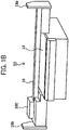
- FIGS. 1A and 1B are perspective views illustrating a general arrangement of a UV inkjet printer (also referred to as an "inkjet recording apparatus") as an example of the apparatus for discharging liquid.
- FIG. 1A is a perspective view as seen from a front side of the apparatus.
- FIG. 1B is a perspective view as seen from a back side of the apparatus.
- a UV inkjet printer 10 includes a carriage 200 and a table (also referred to as a "stage") 13 on which a recording medium is placed.
- the carriage 200 is an inkjet type carriage including a plurality of liquid discharge heads provided with a plurality of nozzles, and discharges liquid from the nozzles of recording heads to form an image.
- the nozzle is provided on a surface facing the table 13.
- the liquid has an ultraviolet curable property as an example.
- an irradiation unit 400 which is a light source for emitting ultraviolet rays is provided.
- the irradiation unit 400 (an example of an irradiator) emits light of a wavelength which cures the liquid discharged from the nozzle.
- a gantry (also referred to as a "guide rod") 19 is stretched between right and left side plates 18a and 18b, and the gantry 19 holds the carriage 200 so as to be movable in an X direction (main-scanning direction).
- the carriage 200, the gantry 19, and the side plates 18a and 18b are integrally movable in a Y direction (sub-scanning direction) along a guide rail 29 provided below the table 13.
- the carriage 200 is held so as to be movable in a Z direction (vertical direction).
- FIG. 2 is a schematic diagram illustrating a basic configuration in which the liquid collecting mechanism of one embodiment is applied to the UV inkjet printer.
- the UV inkjet printer 10 hereinafter also referred to as a "printer” as appropriate
- an apparatus body 11 a liquid discharge head (hereinafter also referred to as a "head” as appropriate) 12
- the table 13 the gantry 19, a liquid collecting mechanism 30, and the carriage 200 are schematically illustrated, and a state in which a medium (recording medium) 9 is placed on the table 13 is illustrated.
- an operation principle of the printer is that printing is performed on a surface of the medium 9 placed on the table 13 by combination of movement of the gantry 19 in the Y (longitudinal) direction and movement of the carriage 200 in the X (horizontal) direction. Since it is required to keep a gap between the surface of the medium 9 and a nozzle surface of the head 12 within a certain range at the time of printing, it is necessary to adjust the carriage in the Z (vertical) direction according to a thickness of the medium 9.
- the apparatus body 11 includes a driver that moves the carriage 200 and the like to a desired position and a controller that controls the entire apparatus.
- the controller controls the entire apparatus by various programs, for example. Detailed description is herein omitted.
- the liquid collecting mechanism 30 includes at least a collecting device 31 and a suction pump 32 as a suction device.
- the printer includes a moving device for moving the collecting device 31 of the liquid collecting mechanism 30 based on the position of the carriage 200 including the liquid discharge head 12.
- the moving device moves the liquid collecting mechanism 30 to a desired position without moving the carriage 200 (in a state in which the carriage 200 is fixed) when collecting residual liquid (waste ink and waste liquid).
- the moving device is controlled by the controller. In this manner, the mechanism becomes simple. By returning the position of the carriage 200 to a height origin without being restricted by the arrangement of the liquid discharge head 12, a gap between the liquid discharge head 12 and the liquid collecting mechanism 30 can be managed.
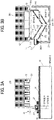
- FIGS. 3A and 3B illustrate the collecting device 31 in a standby state before the residual liquid is collected.
- FIG. 3A is a schematic diagram as seen from the front
- FIG. 3B is a schematic diagram as seen from a right side.
- the carriage 200 and the liquid collecting mechanism 30 stand by at origin positions in the Z (vertical) direction and in the X (horizontal) direction, respectively, by the controller.
- the collecting device 31 includes a funnel-shaped member 311 as a first funnel-shaped member and a funnel-shaped member 312 as a second funnel-shaped member.
- the funnel-shaped member 311 includes a nip 318 in contact with the liquid discharge head 12, an inclination 3111 which receives the liquid, and an opening 3112 provided downstream of the inclination to discharge the liquid.
- the nip 318 is brought into contact with the nozzle surface 121, so that a space A is formed in the funnel-shaped member 311.
- the funnel-shaped member 312 includes an inclination 3121 which receives the liquid and an opening 3122 provided downstream of the inclination to discharge the liquid.
- the funnel-shaped member 312 is arranged below the funnel-shaped member 311 to form a space B between a bottom surface of the funnel-shaped member 311 (a back surface side of the inclination 3111) and the inclination 3121. It is sufficient that the funnel-shaped member has a shape capable of at least receiving the liquid flowing from above and guiding the liquid to the openings 3112 and 3122 by the inclination or the like, and the shape thereof can be changed as appropriate.
- the liquid collecting mechanism 30 includes a tray (also referred to as a "tray") 33 which receives the liquid collected by the collecting device 31, a holder 34 which holds the collecting device 31, a block 35 which supports the holder 34, and a linear guide 36 which guides (defines) a moving direction of the collecting device 31.
- the funnel-shaped members 311 and 312 are provided with one-way valves 313 and 314 at a bottom, respectively.
- Each of the funnel-shaped members 311 and 312 has a funnel shape in which an opening area (inner diameter) of an upper opening facing the head 12 at the time of residual liquid collection is larger than an opening area (inner diameter) of the bottom.
- the funnel-shaped members 311 and 312 are overlapped with a gap through which air (gas) flows therebetween, and include a joint 315 which joins the upper openings of the funnel-shaped members 311 and 312.
- the collecting device 31 includes a suction inlet (also referred to as a "suction port") 316 to take in the air and a suction outlet to exhaust the air sent from the suction inlet 316.
- the suction inlet 316 is provided on an upper part of the upper opening of the funnel-shaped member 311.
- the joint 315 (wall surface joining the funnel-shaped members 311 and 312) extends to the upper part of the upper opening of the funnel-shaped member 311 and is formed to have an opening area (cross-sectional area) smaller than the upper opening of the funnel-shaped member 311.
- the suction outlet 317 is formed at the joint 315 (its location does not matter as long as this is in any part of the space B) so that the air flowing through the gap between the funnel-shaped member 311 and the funnel-shaped member 312 is exhausted.
- the suction outlet 317 is formed such that air may be blown to create a flow opposite to an air flow at the time of residual liquid collection. The opposite flow is described later referring to FIGS. 7A and 7B .
- the suction pump 32 takes in air from the suction inlet 316 and exhausts the air from the suction outlet 317 to generate an air flow.
- the suction pump 32 sucks air to generate (change) an air pressure, thereby opening and closing the one-way valve.
- the opening area (cross-sectional area) of the suction inlet 316 is larger than the opening area (cross-sectional area) at the bottom of the funnel-shaped members 311 and 312.
- the collecting device 31 preferably has at least a portion having a cross-sectional area perpendicular to a direction of flow of the air (air flow) that is larger than a cross-sectional area of the suction inlet 316 perpendicular to the direction of flow of the air.
- FIG. 3B illustrates an example in which the opening area of the upper opening of the funnel-shaped member 311 is one of the cross-sectional areas perpendicular to the direction in which the air flows and is larger than the cross-sectional area of the suction inlet 316.
- an air flow velocity can be modulated.
- the suction inlet is narrowed to form a strong airflow, and air can flow gently in other portions.
- the one-way valves 313 and 314 of the funnel-shaped members 311 and 312, respectively, may be arranged in positions lower than the suction outlet 317. In this manner, a risk that the liquid flows back to the suction inlet 316 can be reduced.
- the collecting device 31 has a double funnel structure in which the two funnel-shaped members 311 and 312 are stacked. In this manner, due to the presence of the funnel-shaped member 311, the liquid dripped from the funnel-shaped member 311 is easily guided to the bottom (the lowest position) that is the central portion of the funnel-shaped member 312. As a result, it can be expected that an effect of preventing the backflow of the liquid is further increased.
- FIGS. 3A and 3B FIGS. 4A , 5A , 6A , and 7A are schematic diagrams as seen from the front and FIGS. 4B , 5B , 6B , and 7B are schematic diagrams as seen from a right side.
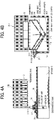
- FIGS. 4A and 4B illustrate a state in which the liquid collecting mechanism 30 starts the residual liquid collection.
- Arrows in the drawing indicate the air flow.
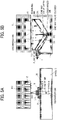
- FIGS. 5A and 5B illustrate a state in which, after the liquid collecting mechanism 30 starts sucking the residual liquid, the collecting device 31 moves.
- the collecting device 31 moves in the Z (horizontal) direction
- the residual ink on the nozzle surface of the liquid discharge head 12 is sequentially collected to be collected in the space B.
- the one-way valve 314 of the funnel-shaped member 312 opens and closes when the air pressure fluctuates due to the suction by the suction pump 32, and the collected ink moves to the tray 33.
- the tray 33 receives the liquid drained from the funnel-shaped member 312.
- FIGS. 6A and 6B illustrate a state immediately after the collection of the residual ink on the nozzle surface of the head 12 is completed.
- the collected waste ink is accumulated at the bottom of the funnel-shaped member 312.
- FIGS. 7A and 7B illustrate a state when the residual liquid recovery is finished.
- the air flow in a blowing direction (opposite direction) from the suction outlet 317, the waste ink accumulated in the space B is allowed to flow into the space C, and the collection of the waste ink is completed.
- the one-way valve opens and closes automatically by the air pressure. In this manner, the waste ink is reliably guided to the tray 33.
- the liquid collecting mechanism of one embodiment collects the residual ink by a fully non-contact system with respect to a plurality of liquid discharge heads with a single suction mechanism.
- a fully non-contact system with respect to a plurality of liquid discharge heads with a single suction mechanism.
- Such a configuration is compatible with various arrangements of the nozzles of the liquid discharge heads, and is not limited by the arrangement of the nozzles.
- the waste ink is collected by the double funnel structure without flowing back to the suction pump. In this manner, it becomes possible to reliably collect the waste ink. Since a mechanical mechanism which collects droplets on the nozzle surface of the liquid discharge head becomes simple, a highly reliable non-contact type liquid collecting mechanism can be provided at a low cost.
- the related art has a disadvantage that the suction mechanism is required for each head and the gap between the nozzle surface of the liquid discharge head and the suction mechanism is difficult, so that a printer manufacturing cost is high and reliability is low. Since a strong suction force is generally required, there is a disadvantage that the sucked ink might flow back to the suction pump. Using the liquid collecting mechanism of one embodiment can resolve the disadvantages.
- the "apparatus for discharging liquid” is the apparatus including the liquid discharge head or the liquid discharge unit to drive the liquid discharge head to discharge liquid.
- Examples of the apparatus for discharging liquid include not only an apparatus capable of discharging the liquid to a material to which the liquid can adhere but also an apparatus which discharges the liquid toward gas or into liquid.
- the "apparatus for discharging liquid” is, for example, the apparatus including the liquid discharge head or the liquid discharge unit and drives the liquid discharge head to discharge liquid.
- the apparatus which discharges liquid include not only an apparatus capable of discharging the liquid to a material to which the liquid can adhere but also an apparatus which discharges the liquid toward gas or into liquid.
- the "apparatus for discharging liquid” may include a device relating to feeding, conveying, and ejecting the material to which the liquid can adhere and also include a preprocessing device and a post-processing device.
- the "apparatus for discharging liquid” may include an image forming apparatus which discharges ink to form an image on paper, and a stereoscopic fabrication apparatus (three-dimensional fabrication apparatus) which discharges fabrication liquid to a powder layer obtained by forming powder into a layer for fabricating a stereoscopic fabrication object (three-dimensional fabrication object).
- an image forming apparatus which discharges ink to form an image on paper
- a stereoscopic fabrication apparatus three-dimensional fabrication apparatus which discharges fabrication liquid to a powder layer obtained by forming powder into a layer for fabricating a stereoscopic fabrication object (three-dimensional fabrication object).
- the "apparatus for discharging liquid” is not limited to an apparatus which visualizes a meaningful image such as a character or a figure by the discharged liquid.
- an apparatus which forms a meaningless pattern, or an apparatus which fabricates a three-dimensional image are also included.
- the "material to which the liquid can adhere” described above is intended to mean the material to which the liquid can adhere at least temporarily, the material to which the liquid adheres to be fastened, or the material to which the liquid adheres to permeate.
- Specific examples include recording media such as paper, recording paper, a recording sheet, a film, and cloth, electronic components such as an electronic substrate and a piezoelectric element, and media such as a powder layer, an organ model, and a testing cell; all the materials to which the liquid adheres are included unless limited in particular.
- the "material to which the liquid can adhere” described above may be any material as long as the liquid can adhere thereto even if temporarily such as paper, thread, fiber, cloth, leather, metal, plastic, glass, wood, and ceramics.
- the “liquid” is not limited in particular as long as this has viscosity and surface tension capable of being discharged from the head, but the viscosity is preferably 30 mPa ⁇ s or less at room temperature and normal pressure, or by heating or cooling. More specifically, this is solution, suspension, emulsion and the like including solvents such as water and organic solvents, colorants such as dyes and pigments, functional materials such as polymerizable compounds, resins, and surfactants, biocompatible materials such as deoxyribonucleic acid (DNA), amino acids, proteins, and calcium, edible materials such as natural pigments and the like; they may be used as, for example, ink for inkjet, surface treatment liquid, formation liquid of components of electronic elements and light emitting elements, and electronic circuit resist pattern, and material liquid for three-dimensional fabrication.
- solvents such as water and organic solvents
- colorants such as dyes and pigments
- functional materials such as polymerizable compounds, resins, and surfactants
- biocompatible materials such as deoxyribonu
- the "apparatus for discharging liquid” may include an apparatus in which the liquid discharge head and the material to which the liquid can adhere relatively move; however, this is not limited to such an apparatus. Specific examples include a serial type apparatus which moves the liquid discharge head, and a line type apparatus which does not move the liquid discharge head.
- the "apparatus for discharging liquid” also includes a treatment liquid applying apparatus for discharging a treatment liquid onto paper for applying the treatment liquid to the surface of the paper for the purpose of modifying the surface of the paper, an injection granulating apparatus which granulates fine particles of a raw material by injecting a composition liquid obtained by dispersing the raw material in a solution through a nozzle and the like.
Landscapes
- Engineering & Computer Science (AREA)
- Environmental & Geological Engineering (AREA)
- Ink Jet (AREA)
- Coating Apparatus (AREA)
Abstract
Description
- The present invention relates to an apparatus for discharging liquid.
- In an ultraviolet (UV) inkjet printer, a technology of collecting residual ink on a nozzle surface by a non-contact suction type considering reduction of wear on the nozzle surface of the liquid discharge head is considered and already known (for example,
JP-2016-000516-A - In
JP-2016-000516-A - An object of the present invention is to reliably collect residual ink.
- In an aspect of the present invention, there is provided an apparatus for discharging liquid. The apparatus includes a liquid collecting mechanism to collect liquid from a liquid discharge head. The liquid collecting mechanism includes a first funnel-shaped member to contact the liquid discharge head, a second funnel-shaped member below the first funnel-shaped member, a suction device connected to the second funnel-shaped member, and a tray to receive the liquid from the second funnel-shaped member.
- According to the present invention, the residual ink can be reliably collected.
- The aforementioned and other aspects, features, and advantages of the present disclosure would be better understood by reference to the following detailed description when considered in connection with the accompanying drawings, wherein:
-
FIGS. 1A and1B are perspective views illustrating a general arrangement in an example of an apparatus for discharging liquid according to an embodiment of the present invention; -
FIG. 2 is a schematic diagram illustrating a basic configuration of a UV inkjet printer to which a liquid collecting mechanism according to one embodiment is applied; -
FIGS. 3A and 3B are schematic diagrams illustrating a collecting device when the liquid collecting mechanism of one embodiment is in a standby state; -
FIGS. 4A and 4B are schematic diagrams illustrating the collecting device when the liquid collecting mechanism of one embodiment starts collecting residual liquid; -
FIGS. 5A and 5B are schematic diagrams illustrating the collecting device when the liquid collecting mechanism of one embodiment is in a sucking state; -
FIGS. 6A and 6B are schematic diagrams illustrating the collecting device immediately after the liquid collecting mechanism of one embodiment completes sucking; and -
FIGS. 7A and 7B are schematic diagrams for illustrating the collecting device when the liquid collecting mechanism of one embodiment finishes collecting the residual liquid. - The accompanying drawings are intended to depict embodiments of the present disclosure and should not be interpreted to limit the scope thereof. The accompanying drawings are not to be considered as drawn to scale unless explicitly noted.
- In describing embodiments illustrated in the drawings, specific terminology is employed for the sake of clarity. However, the disclosure of this patent specification is not intended to be limited to the specific terminology so selected and it is to be understood that each specific element includes all technical equivalents that operate in a similar manner and achieve similar results.
- Although the embodiments are described with technical limitations with reference to the attached drawings, such description is not intended to limit the scope of the disclosure and all of the components or elements described in the embodiments of this disclosure are not necessarily indispensable.
- Referring now to the drawings, embodiments of the present disclosure are described below. In the drawings for explaining the following embodiments, the same reference codes are allocated to elements (members or components) having the same function or shape and redundant descriptions thereof are omitted below.
- Hereinafter, an embodiment is described referring to the drawings. For clarity of the description, the following description and drawings are omitted or simplified as appropriate. In the drawings, components having the same configuration or function and corresponding parts are assigned with the same reference numerals, and the description thereof is omitted.
- First, a general arrangement of one embodiment of an apparatus for discharging liquid according to an embodiment of the present invention is described.
FIGS. 1A and1B are perspective views illustrating a general arrangement of a UV inkjet printer (also referred to as an "inkjet recording apparatus") as an example of the apparatus for discharging liquid.FIG. 1A is a perspective view as seen from a front side of the apparatus.FIG. 1B is a perspective view as seen from a back side of the apparatus. - A
UV inkjet printer 10 includes acarriage 200 and a table (also referred to as a "stage") 13 on which a recording medium is placed. Thecarriage 200 is an inkjet type carriage including a plurality of liquid discharge heads provided with a plurality of nozzles, and discharges liquid from the nozzles of recording heads to form an image. The nozzle is provided on a surface facing the table 13. In this embodiment, the liquid has an ultraviolet curable property as an example. - On the surface facing the table 13 of the
carriage 200, anirradiation unit 400 which is a light source for emitting ultraviolet rays is provided. The irradiation unit 400 (an example of an irradiator) emits light of a wavelength which cures the liquid discharged from the nozzle. - A gantry (also referred to as a "guide rod") 19 is stretched between right and
left side plates gantry 19 holds thecarriage 200 so as to be movable in an X direction (main-scanning direction). Thecarriage 200, thegantry 19, and theside plates guide rail 29 provided below the table 13. Thecarriage 200 is held so as to be movable in a Z direction (vertical direction). - Next, a relationship between an entire liquid discharge apparatus and a liquid collecting mechanism of one embodiment is described referring to
FIG. 2. FIG. 2 is a schematic diagram illustrating a basic configuration in which the liquid collecting mechanism of one embodiment is applied to the UV inkjet printer. InFIG. 2 , as for the UV inkjet printer 10 (hereinafter also referred to as a "printer" as appropriate) as an example of the apparatus for discharging liquid, anapparatus body 11, a liquid discharge head (hereinafter also referred to as a "head" as appropriate) 12, the table 13, thegantry 19, aliquid collecting mechanism 30, and thecarriage 200 are schematically illustrated, and a state in which a medium (recording medium) 9 is placed on the table 13 is illustrated. - As described above, an operation principle of the printer is that printing is performed on a surface of the medium 9 placed on the table 13 by combination of movement of the
gantry 19 in the Y (longitudinal) direction and movement of thecarriage 200 in the X (horizontal) direction. Since it is required to keep a gap between the surface of the medium 9 and a nozzle surface of thehead 12 within a certain range at the time of printing, it is necessary to adjust the carriage in the Z (vertical) direction according to a thickness of the medium 9. - The
apparatus body 11 includes a driver that moves thecarriage 200 and the like to a desired position and a controller that controls the entire apparatus. The controller controls the entire apparatus by various programs, for example. Detailed description is herein omitted. - The
liquid collecting mechanism 30 includes at least acollecting device 31 and asuction pump 32 as a suction device. The printer includes a moving device for moving thecollecting device 31 of theliquid collecting mechanism 30 based on the position of thecarriage 200 including theliquid discharge head 12. The moving device moves theliquid collecting mechanism 30 to a desired position without moving the carriage 200 (in a state in which thecarriage 200 is fixed) when collecting residual liquid (waste ink and waste liquid). The moving device is controlled by the controller. In this manner, the mechanism becomes simple. By returning the position of thecarriage 200 to a height origin without being restricted by the arrangement of theliquid discharge head 12, a gap between theliquid discharge head 12 and theliquid collecting mechanism 30 can be managed. - Next, the collecting
device 31 of the liquid collecting mechanism of one embodiment is described.FIGS. 3A and 3B illustrate the collectingdevice 31 in a standby state before the residual liquid is collected.FIG. 3A is a schematic diagram as seen from the front, andFIG. 3B is a schematic diagram as seen from a right side. Thecarriage 200 and theliquid collecting mechanism 30 stand by at origin positions in the Z (vertical) direction and in the X (horizontal) direction, respectively, by the controller. - Herein, a configuration example of the
liquid collecting mechanism 30 is described. The collectingdevice 31 includes a funnel-shapedmember 311 as a first funnel-shaped member and a funnel-shapedmember 312 as a second funnel-shaped member. The funnel-shapedmember 311 includes a nip 318 in contact with theliquid discharge head 12, aninclination 3111 which receives the liquid, and anopening 3112 provided downstream of the inclination to discharge the liquid. Thenip 318 is brought into contact with thenozzle surface 121, so that a space A is formed in the funnel-shapedmember 311. The funnel-shapedmember 312 includes aninclination 3121 which receives the liquid and anopening 3122 provided downstream of the inclination to discharge the liquid. The funnel-shapedmember 312 is arranged below the funnel-shapedmember 311 to form a space B between a bottom surface of the funnel-shaped member 311 (a back surface side of the inclination 3111) and theinclination 3121. It is sufficient that the funnel-shaped member has a shape capable of at least receiving the liquid flowing from above and guiding the liquid to theopenings liquid collecting mechanism 30 includes a tray (also referred to as a "tray") 33 which receives the liquid collected by the collectingdevice 31, aholder 34 which holds the collectingdevice 31, ablock 35 which supports theholder 34, and alinear guide 36 which guides (defines) a moving direction of the collectingdevice 31. - The funnel-shaped
members way valves members head 12 at the time of residual liquid collection is larger than an opening area (inner diameter) of the bottom. The funnel-shapedmembers members - The collecting
device 31 includes a suction inlet (also referred to as a "suction port") 316 to take in the air and a suction outlet to exhaust the air sent from thesuction inlet 316. Thesuction inlet 316 is provided on an upper part of the upper opening of the funnel-shapedmember 311. InFIG. 3B , the joint 315 (wall surface joining the funnel-shapedmembers 311 and 312) extends to the upper part of the upper opening of the funnel-shapedmember 311 and is formed to have an opening area (cross-sectional area) smaller than the upper opening of the funnel-shapedmember 311. Thesuction outlet 317 is formed at the joint 315 (its location does not matter as long as this is in any part of the space B) so that the air flowing through the gap between the funnel-shapedmember 311 and the funnel-shapedmember 312 is exhausted. Thesuction outlet 317 is formed such that air may be blown to create a flow opposite to an air flow at the time of residual liquid collection. The opposite flow is described later referring toFIGS. 7A and 7B . - The
suction pump 32 takes in air from thesuction inlet 316 and exhausts the air from thesuction outlet 317 to generate an air flow. Thesuction pump 32 sucks air to generate (change) an air pressure, thereby opening and closing the one-way valve. - The opening area (cross-sectional area) of the
suction inlet 316 is larger than the opening area (cross-sectional area) at the bottom of the funnel-shapedmembers device 31 preferably has at least a portion having a cross-sectional area perpendicular to a direction of flow of the air (air flow) that is larger than a cross-sectional area of thesuction inlet 316 perpendicular to the direction of flow of the air. For example,FIG. 3B illustrates an example in which the opening area of the upper opening of the funnel-shapedmember 311 is one of the cross-sectional areas perpendicular to the direction in which the air flows and is larger than the cross-sectional area of thesuction inlet 316. In this manner, when sucking with thesuction pump 32, an air flow velocity can be modulated. In detail, in order to prevent the liquid from flowing along with the airflow, the suction inlet is narrowed to form a strong airflow, and air can flow gently in other portions. The one-way valves members suction outlet 317. In this manner, a risk that the liquid flows back to thesuction inlet 316 can be reduced. - As described above, the collecting
device 31 has a double funnel structure in which the two funnel-shapedmembers member 311, the liquid dripped from the funnel-shapedmember 311 is easily guided to the bottom (the lowest position) that is the central portion of the funnel-shapedmember 312. As a result, it can be expected that an effect of preventing the backflow of the liquid is further increased. - Hereinafter, an example of a mechanism by which the
liquid collecting mechanism 30 performs the residual liquid collection from the standby state is described. At that time, the direction in which the air flows in the collectingdevice 31 is described using the space A, space B, and space C illustrated inFIGS. 3A and 3B . As inFIGS. 3A and 3B ,FIGS. 4A ,5A ,6A , and7A are schematic diagrams as seen from the front andFIGS. 4B ,5B ,6B , and7B are schematic diagrams as seen from a right side. -
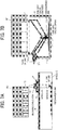
FIGS. 4A and 4B illustrate a state in which theliquid collecting mechanism 30 starts the residual liquid collection. Arrows in the drawing indicate the air flow. When an appropriate amount of liquid is pushed out from the nozzle of thehead 12 and thesuction pump 32 starts sucking, an air flow is generated in the order from thesuction inlet 316, the space A, the space B, and thesuction outlet 317. As a result, the pushed waste ink falls into the space C. The one-way valve opens and closes automatically by the air pressure. -
FIGS. 5A and 5B illustrate a state in which, after theliquid collecting mechanism 30 starts sucking the residual liquid, the collectingdevice 31 moves. As the collectingdevice 31 moves in the Z (horizontal) direction, the residual ink on the nozzle surface of theliquid discharge head 12 is sequentially collected to be collected in the space B. During this time, the one-way valve 314 of the funnel-shapedmember 312 opens and closes when the air pressure fluctuates due to the suction by thesuction pump 32, and the collected ink moves to thetray 33. Thetray 33 receives the liquid drained from the funnel-shapedmember 312. -
FIGS. 6A and 6B illustrate a state immediately after the collection of the residual ink on the nozzle surface of thehead 12 is completed. The collected waste ink is accumulated at the bottom of the funnel-shapedmember 312. -
FIGS. 7A and 7B illustrate a state when the residual liquid recovery is finished. By forming the air flow in a blowing direction (opposite direction) from thesuction outlet 317, the waste ink accumulated in the space B is allowed to flow into the space C, and the collection of the waste ink is completed. The one-way valve opens and closes automatically by the air pressure. In this manner, the waste ink is reliably guided to thetray 33. - As described above, the liquid collecting mechanism of one embodiment collects the residual ink by a fully non-contact system with respect to a plurality of liquid discharge heads with a single suction mechanism. Such a configuration is compatible with various arrangements of the nozzles of the liquid discharge heads, and is not limited by the arrangement of the nozzles. The waste ink is collected by the double funnel structure without flowing back to the suction pump. In this manner, it becomes possible to reliably collect the waste ink. Since a mechanical mechanism which collects droplets on the nozzle surface of the liquid discharge head becomes simple, a highly reliable non-contact type liquid collecting mechanism can be provided at a low cost. For example, the related art has a disadvantage that the suction mechanism is required for each head and the gap between the nozzle surface of the liquid discharge head and the suction mechanism is difficult, so that a printer manufacturing cost is high and reliability is low. Since a strong suction force is generally required, there is a disadvantage that the sucked ink might flow back to the suction pump. Using the liquid collecting mechanism of one embodiment can resolve the disadvantages.
- The "apparatus for discharging liquid" is the apparatus including the liquid discharge head or the liquid discharge unit to drive the liquid discharge head to discharge liquid. Examples of the apparatus for discharging liquid include not only an apparatus capable of discharging the liquid to a material to which the liquid can adhere but also an apparatus which discharges the liquid toward gas or into liquid.
- In embodiments of the present invention, the "apparatus for discharging liquid" is, for example, the apparatus including the liquid discharge head or the liquid discharge unit and drives the liquid discharge head to discharge liquid. Examples of the apparatus which discharges liquid include not only an apparatus capable of discharging the liquid to a material to which the liquid can adhere but also an apparatus which discharges the liquid toward gas or into liquid.
- The "apparatus for discharging liquid" may include a device relating to feeding, conveying, and ejecting the material to which the liquid can adhere and also include a preprocessing device and a post-processing device.
- For example, the "apparatus for discharging liquid" may include an image forming apparatus which discharges ink to form an image on paper, and a stereoscopic fabrication apparatus (three-dimensional fabrication apparatus) which discharges fabrication liquid to a powder layer obtained by forming powder into a layer for fabricating a stereoscopic fabrication object (three-dimensional fabrication object).
- The "apparatus for discharging liquid" is not limited to an apparatus which visualizes a meaningful image such as a character or a figure by the discharged liquid. For example, an apparatus which forms a meaningless pattern, or an apparatus which fabricates a three-dimensional image are also included.
- The "material to which the liquid can adhere" described above is intended to mean the material to which the liquid can adhere at least temporarily, the material to which the liquid adheres to be fastened, or the material to which the liquid adheres to permeate. Specific examples include recording media such as paper, recording paper, a recording sheet, a film, and cloth, electronic components such as an electronic substrate and a piezoelectric element, and media such as a powder layer, an organ model, and a testing cell; all the materials to which the liquid adheres are included unless limited in particular.
- The "material to which the liquid can adhere" described above may be any material as long as the liquid can adhere thereto even if temporarily such as paper, thread, fiber, cloth, leather, metal, plastic, glass, wood, and ceramics.
- The "liquid" is not limited in particular as long as this has viscosity and surface tension capable of being discharged from the head, but the viscosity is preferably 30 mPa · s or less at room temperature and normal pressure, or by heating or cooling. More specifically, this is solution, suspension, emulsion and the like including solvents such as water and organic solvents, colorants such as dyes and pigments, functional materials such as polymerizable compounds, resins, and surfactants, biocompatible materials such as deoxyribonucleic acid (DNA), amino acids, proteins, and calcium, edible materials such as natural pigments and the like; they may be used as, for example, ink for inkjet, surface treatment liquid, formation liquid of components of electronic elements and light emitting elements, and electronic circuit resist pattern, and material liquid for three-dimensional fabrication.
- The "apparatus for discharging liquid" may include an apparatus in which the liquid discharge head and the material to which the liquid can adhere relatively move; however, this is not limited to such an apparatus. Specific examples include a serial type apparatus which moves the liquid discharge head, and a line type apparatus which does not move the liquid discharge head.
- The "apparatus for discharging liquid" also includes a treatment liquid applying apparatus for discharging a treatment liquid onto paper for applying the treatment liquid to the surface of the paper for the purpose of modifying the surface of the paper, an injection granulating apparatus which granulates fine particles of a raw material by injecting a composition liquid obtained by dispersing the raw material in a solution through a nozzle and the like.
- Numerous additional modifications and variations are possible in light of the above teachings. It is therefore to be understood that, within the scope of the above teachings, the present disclosure may be practiced otherwise than as specifically described herein. With some embodiments having thus been described, it will be obvious that the same may be varied in many ways. Such variations are not to be regarded as a departure from the scope of the present disclosure and appended claims, and all such modifications are intended to be included within the scope of the present disclosure and appended claims.
Claims (6)
- An apparatus for discharging liquid, the apparatus comprising a liquid collecting mechanism (30) to collect liquid from a liquid discharge head (12),
the liquid collecting mechanism (30) including:a first funnel-shaped member (311) to contact the liquid discharge head (12);a second funnel-shaped member (312) below the first funnel-shaped member (311);a suction device (32) connected to the second funnel-shaped member (312); anda tray (30) to receive the liquid from the second funnel-shaped member (312). - The apparatus according to claim 1, further comprising a moving device configured to move the first funnel-shaped member (311) and the second funnel-shaped member (312).
- The apparatus according to claim 1 or 2, further comprising a collecting device (31) including the first funnel-shaped member (311) and the second funnel-shaped member (312),wherein the collecting device (31) includes:a suction inlet (316) to take in air ; anda suction outlet (317) to exhaust the air, andwherein the collecting device (31) includes a portion having a cross-sectional area perpendicular to a direction of flow of the air that is larger than a cross-sectional area of the suction inlet (316) perpendicular to the direction of flow of the air.
- The apparatus according to any one of claims 1 to 3,
wherein the first funnel-shaped member (311) includes a one-way valve (313) at a bottom of the first funnel-shaped member (311). - The apparatus according to any one of claims 1 to 4,
wherein the second funnel-shaped member (312) includes a one-way valve (314) at a bottom of the second funnel-shaped member (312). - The apparatus according to claim 1 or 2, further comprising a collecting device (31) including the first funnel-shaped member (311) and the second funnel-shaped member (312),wherein the first funnel-shaped member (311) includes a first one-way valve (313) at a bottom of the first funnel-shaped member (311),wherein the second funnel-shaped member (312) includes a second one-way valve (314) at a bottom of the second funnel-shaped member (312),wherein the collecting device (31) includes:a suction inlet (316) to take in air; anda suction outlet (317) to exhaust the air, andwherein at least one of the first one-way valve (313) and the second one-way valve (314) is located at a position lower than the suction outlet.
Applications Claiming Priority (1)
| Application Number | Priority Date | Filing Date | Title |
|---|---|---|---|
| JP2019047061A JP2020146945A (en) | 2019-03-14 | 2019-03-14 | Device that discharges liquid |
Publications (1)
| Publication Number | Publication Date |
|---|---|
| EP3708375A1 true EP3708375A1 (en) | 2020-09-16 |
Family
ID=69780089
Family Applications (1)
| Application Number | Title | Priority Date | Filing Date |
|---|---|---|---|
| EP20161621.6A Withdrawn EP3708375A1 (en) | 2019-03-14 | 2020-03-06 | Apparatus for discharging liquid |
Country Status (2)
| Country | Link |
|---|---|
| EP (1) | EP3708375A1 (en) |
| JP (1) | JP2020146945A (en) |
Families Citing this family (1)
| Publication number | Priority date | Publication date | Assignee | Title |
|---|---|---|---|---|
| JP7543789B2 (en) | 2020-09-01 | 2024-09-03 | 住友電気工業株式会社 | Multi-core optical fiber and multi-core optical fiber cable |
Citations (4)
| Publication number | Priority date | Publication date | Assignee | Title |
|---|---|---|---|---|
| US6478402B1 (en) * | 1999-06-28 | 2002-11-12 | Heidelberger Druckmaschinen Ag | Method and device for cleaning a nozzle outlet surface on a print head of an ink jet printer |
| US20130241995A1 (en) * | 2012-03-14 | 2013-09-19 | Seiko Epson Corporation | Liquid ejecting apparatus |
| US20140060662A1 (en) * | 2012-08-28 | 2014-03-06 | Randolph E. Dumas | Method of maintaining an inkjet printhead |
| JP2016000516A (en) | 2014-05-21 | 2016-01-07 | 株式会社リコー | Droplet discharge head recovery mechanism |
-
2019
- 2019-03-14 JP JP2019047061A patent/JP2020146945A/en active Pending
-
2020
- 2020-03-06 EP EP20161621.6A patent/EP3708375A1/en not_active Withdrawn
Patent Citations (4)
| Publication number | Priority date | Publication date | Assignee | Title |
|---|---|---|---|---|
| US6478402B1 (en) * | 1999-06-28 | 2002-11-12 | Heidelberger Druckmaschinen Ag | Method and device for cleaning a nozzle outlet surface on a print head of an ink jet printer |
| US20130241995A1 (en) * | 2012-03-14 | 2013-09-19 | Seiko Epson Corporation | Liquid ejecting apparatus |
| US20140060662A1 (en) * | 2012-08-28 | 2014-03-06 | Randolph E. Dumas | Method of maintaining an inkjet printhead |
| JP2016000516A (en) | 2014-05-21 | 2016-01-07 | 株式会社リコー | Droplet discharge head recovery mechanism |
Also Published As
| Publication number | Publication date |
|---|---|
| JP2020146945A (en) | 2020-09-17 |
Similar Documents
| Publication | Publication Date | Title |
|---|---|---|
| JP6019954B2 (en) | Image forming apparatus | |
| US9102163B2 (en) | Droplet ejection apparatus and maintenance method thereof | |
| US10759171B2 (en) | Liquid discharge apparatus | |
| US10486361B2 (en) | Liquid supply apparatus, liquid discharge apparatus, and three-dimensional fabricating apparatus | |
| US7520598B2 (en) | Printer deflector mechanism including liquid flow | |
| JP2013063559A (en) | Inkjet recording device | |
| US20200298582A1 (en) | Liquid discharge head, head module, head unit, liquid discharge device, and liquid discharge apparatus | |
| EP3708375A1 (en) | Apparatus for discharging liquid | |
| JP5995184B2 (en) | Image forming apparatus | |
| US20220017359A1 (en) | Liquid supply device, liquid discharge device, and liquid discharge apparatus | |
| US20230202180A1 (en) | Waste liquid collection device and liquid discharge apparatus | |
| JP6683946B2 (en) | Liquid ejection head and liquid ejection device | |
| JP2021123103A (en) | Liquid discharge device | |
| JP6707891B2 (en) | Liquid ejection head, liquid ejection unit, device for ejecting liquid | |
| JP2017200740A (en) | Liquid discharge unit and liquid discharge device | |
| JP7076270B2 (en) | Ink supply device and 3D object forming device | |
| JP7589027B2 (en) | Recording apparatus and control method thereof | |
| US12508810B2 (en) | Liquid discharge apparatus and cleaning method | |
| US20220373461A1 (en) | Recording apparatus | |
| JP7625992B2 (en) | Mist collection device and liquid ejection device | |
| JP7069780B2 (en) | Mist recovery device, liquid discharge device | |
| JP2023123123A (en) | Liquid ejection device and imprint device | |
| JP7463711B2 (en) | Liquid storage container and liquid ejection device | |
| EP4205984B1 (en) | Maintenance device, liquid discharge device, and liquid discharge apparatus | |
| JP2010005993A (en) | Substrate joining method, joined substrate, inkjet head, and image forming apparatus |
Legal Events
| Date | Code | Title | Description |
|---|---|---|---|
| PUAI | Public reference made under article 153(3) epc to a published international application that has entered the european phase |
Free format text: ORIGINAL CODE: 0009012 |
|
| STAA | Information on the status of an ep patent application or granted ep patent |
Free format text: STATUS: REQUEST FOR EXAMINATION WAS MADE |
|
| 17P | Request for examination filed |
Effective date: 20200306 |
|
| AK | Designated contracting states |
Kind code of ref document: A1 Designated state(s): AL AT BE BG CH CY CZ DE DK EE ES FI FR GB GR HR HU IE IS IT LI LT LU LV MC MK MT NL NO PL PT RO RS SE SI SK SM TR |
|
| AX | Request for extension of the european patent |
Extension state: BA ME |
|
| STAA | Information on the status of an ep patent application or granted ep patent |
Free format text: STATUS: EXAMINATION IS IN PROGRESS |
|
| 17Q | First examination report despatched |
Effective date: 20220228 |
|
| STAA | Information on the status of an ep patent application or granted ep patent |
Free format text: STATUS: THE APPLICATION HAS BEEN WITHDRAWN |
|
| 18W | Application withdrawn |
Effective date: 20220505 |