EP3708248A1 - Apparatus and method for preparing polymer latex resin powder - Google Patents
Apparatus and method for preparing polymer latex resin powder Download PDFInfo
- Publication number
- EP3708248A1 EP3708248A1 EP18875077.2A EP18875077A EP3708248A1 EP 3708248 A1 EP3708248 A1 EP 3708248A1 EP 18875077 A EP18875077 A EP 18875077A EP 3708248 A1 EP3708248 A1 EP 3708248A1
- Authority
- EP
- European Patent Office
- Prior art keywords
- flocculation tank
- polymer latex
- resin powder
- region
- discharge line
- Prior art date
- Legal status (The legal status is an assumption and is not a legal conclusion. Google has not performed a legal analysis and makes no representation as to the accuracy of the status listed.)
- Granted
Links
Images


Classifications
-
- B—PERFORMING OPERATIONS; TRANSPORTING
- B01—PHYSICAL OR CHEMICAL PROCESSES OR APPARATUS IN GENERAL
- B01J—CHEMICAL OR PHYSICAL PROCESSES, e.g. CATALYSIS OR COLLOID CHEMISTRY; THEIR RELEVANT APPARATUS
- B01J2/00—Processes or devices for granulating materials, e.g. fertilisers in general; Rendering particulate materials free flowing in general, e.g. making them hydrophobic
- B01J2/10—Processes or devices for granulating materials, e.g. fertilisers in general; Rendering particulate materials free flowing in general, e.g. making them hydrophobic in stationary drums or troughs, provided with kneading or mixing appliances
-
- C—CHEMISTRY; METALLURGY
- C08—ORGANIC MACROMOLECULAR COMPOUNDS; THEIR PREPARATION OR CHEMICAL WORKING-UP; COMPOSITIONS BASED THEREON
- C08J—WORKING-UP; GENERAL PROCESSES OF COMPOUNDING; AFTER-TREATMENT NOT COVERED BY SUBCLASSES C08B, C08C, C08F, C08G or C08H
- C08J3/00—Processes of treating or compounding macromolecular substances
- C08J3/12—Powdering or granulating
- C08J3/16—Powdering or granulating by coagulating dispersions
-
- B—PERFORMING OPERATIONS; TRANSPORTING
- B01—PHYSICAL OR CHEMICAL PROCESSES OR APPARATUS IN GENERAL
- B01F—MIXING, e.g. DISSOLVING, EMULSIFYING OR DISPERSING
- B01F27/00—Mixers with rotary stirring devices in fixed receptacles; Kneaders
- B01F27/05—Stirrers
- B01F27/11—Stirrers characterised by the configuration of the stirrers
- B01F27/19—Stirrers with two or more mixing elements mounted in sequence on the same axis
- B01F27/191—Stirrers with two or more mixing elements mounted in sequence on the same axis with similar elements
-
- B—PERFORMING OPERATIONS; TRANSPORTING
- B01—PHYSICAL OR CHEMICAL PROCESSES OR APPARATUS IN GENERAL
- B01F—MIXING, e.g. DISSOLVING, EMULSIFYING OR DISPERSING
- B01F27/00—Mixers with rotary stirring devices in fixed receptacles; Kneaders
- B01F27/80—Mixers with rotary stirring devices in fixed receptacles; Kneaders with stirrers rotating about a substantially vertical axis
- B01F27/90—Mixers with rotary stirring devices in fixed receptacles; Kneaders with stirrers rotating about a substantially vertical axis with paddles or arms
- B01F27/906—Mixers with rotary stirring devices in fixed receptacles; Kneaders with stirrers rotating about a substantially vertical axis with paddles or arms with fixed axis
-
- B—PERFORMING OPERATIONS; TRANSPORTING
- B01—PHYSICAL OR CHEMICAL PROCESSES OR APPARATUS IN GENERAL
- B01F—MIXING, e.g. DISSOLVING, EMULSIFYING OR DISPERSING
- B01F33/00—Other mixers; Mixing plants; Combinations of mixers
- B01F33/80—Mixing plants; Combinations of mixers
- B01F33/81—Combinations of similar mixers, e.g. with rotary stirring devices in two or more receptacles
- B01F33/811—Combinations of similar mixers, e.g. with rotary stirring devices in two or more receptacles in two or more consecutive, i.e. successive, mixing receptacles or being consecutively arranged
-
- B—PERFORMING OPERATIONS; TRANSPORTING
- B01—PHYSICAL OR CHEMICAL PROCESSES OR APPARATUS IN GENERAL
- B01J—CHEMICAL OR PHYSICAL PROCESSES, e.g. CATALYSIS OR COLLOID CHEMISTRY; THEIR RELEVANT APPARATUS
- B01J19/00—Chemical, physical or physico-chemical processes in general; Their relevant apparatus
- B01J19/0053—Details of the reactor
- B01J19/0066—Stirrers
-
- B—PERFORMING OPERATIONS; TRANSPORTING
- B01—PHYSICAL OR CHEMICAL PROCESSES OR APPARATUS IN GENERAL
- B01J—CHEMICAL OR PHYSICAL PROCESSES, e.g. CATALYSIS OR COLLOID CHEMISTRY; THEIR RELEVANT APPARATUS
- B01J19/00—Chemical, physical or physico-chemical processes in general; Their relevant apparatus
- B01J19/18—Stationary reactors having moving elements inside
-
- C—CHEMISTRY; METALLURGY
- C08—ORGANIC MACROMOLECULAR COMPOUNDS; THEIR PREPARATION OR CHEMICAL WORKING-UP; COMPOSITIONS BASED THEREON
- C08F—MACROMOLECULAR COMPOUNDS OBTAINED BY REACTIONS ONLY INVOLVING CARBON-TO-CARBON UNSATURATED BONDS
- C08F2/00—Processes of polymerisation
- C08F2/01—Processes of polymerisation characterised by special features of the polymerisation apparatus used
-
- C—CHEMISTRY; METALLURGY
- C08—ORGANIC MACROMOLECULAR COMPOUNDS; THEIR PREPARATION OR CHEMICAL WORKING-UP; COMPOSITIONS BASED THEREON
- C08J—WORKING-UP; GENERAL PROCESSES OF COMPOUNDING; AFTER-TREATMENT NOT COVERED BY SUBCLASSES C08B, C08C, C08F, C08G or C08H
- C08J2321/00—Characterised by the use of unspecified rubbers
- C08J2321/02—Latex
Definitions
- the present invention relates to an apparatus and a method for producing a polymer latex resin powder.
- slow coagulation is used as a method for preparing a polymer latex as a powder in an emulsion polymerization process, and in this method, an aqueous solution of a flocculant such as an inorganic salt and an acid is divided in small amounts and added to break stability of an emulsifier, whereby the polymer in the latex is agglomerated.
- a flocculant such as an inorganic salt and an acid
- the slow coagulation method is capable of controlling the particle size as compared with a rapid coagulation method.
- a process of agglomerating polymer particles in the latex is called coagulation and one in which the polymer particles are agglomerated is called a slurry, where they are in a physically weakly bonded state, and thus show an easy break-up phenomenon by shear force by a stirrer (for example, an impeller).
- the primarily coagulated slurry is subjected to an aging process.
- the slurry thus generated is subjected to dehydrating and drying processes to finally obtain a powdery phase.
- fine particles having an average particle diameter of about 75 ⁇ m or less are called “fine” particles and larger particles having an average particle diameter of about 800 ⁇ m or more are called “coarse” particles.
- the fine particles deteriorate the performance of the dehydrator and the dryer of the latex resin powder and are easily scattered into the air, which cause many problems in transport and packing of the powder in the process, and the coarse particles have a problem of transport and storage and have a disadvantage that compatibility with other polymer resins is poor.
- Figure 1 is a conceptual diagram showing a conventional apparatus (10) for producing a polymer latex resin powder.
- the production apparatus (10) comprises a flocculation tank (11), a plurality of supply lines (12) for supplying a polymer latex, a flocculant and water, and the like into the flocculation tank, a stirring part (20) provided in the flocculation tank (11) and a discharge line (13).
- the flocculation tank (11) has been provided so as to operate in an open system. Specifically, the flocculation tank (11) is maintained at a predetermined slurry level, and an air layer (14) is formed on the top of the flocculation tank (11).
- an apparatus for producing a polymer latex resin powder comprising a first flocculation tank to which a polymer latex and a flocculant are each supplied, wherein the first flocculation tank is provided with a stirring part including a rotation axis and one or more impellers mounted on the rotation axis, and a discharge line, respectively and the first flocculation tank is provided so as to operate in a closed system upon operating the stirring part.
- the discharge line is connected to the top region of the first flocculation tank, whereby the first flocculation tank is provided so as to operate in a closed system upon operating the stirring part.
- the discharge line is connected along the tangential direction to the first flocculation tank.
- the discharge line is connected to the first flocculation tank so as to be inclined at a predetermined angle based on the rotation axis of the stirring part.
- the angle may be 45°.
- first and second supply lines to which the polymer latex and the flocculant are each supplied, may be connected to the first flocculation tank.
- first and second supply lines may be each connected to the bottom region of the first flocculation tank and may be provided so that the polymer latex and the flocculant are each supplied to the end side of the impeller.
- the apparatus for producing a polymer latex resin powder may further comprise a second flocculation tank into which the polymer slurry discharged from the first flocculation tank flows.
- the discharge line may be connected to the second flocculation tank at a height lower than the slurry level of the second flocculation tank.
- the discharge line may comprise a first region connected to the first flocculation tank and a second region connected to the second flocculation tank.
- boundary between the first region and the second region may be located above the uppermost end of the first flocculation tank.
- first region and the second region of the discharge line may be connected at a predetermined angle.
- both the first flocculation tank and the discharge line are each filled with the polymer slurry upon operating the stirring part.
- a method for producing a polymer latex resin powder comprising steps of supplying a polymer latex and a flocculant to a first flocculation tank, stirring the polymer latex and flocculant in the first flocculation tank in a closed system and supplying the polymer slurry in the first flocculation tank into a second flocculation tank.
- the apparatus and method for producing a polymer latex resin powder related to at least one example of the present invention have the following effects.
- the flocculation tank As the flocculation tank is provided so as to operate in a closed system upon stirring the polymer slurry, the fine and coarse particles can be reduced and the uniform shear force can be applied to the polymer slurry through the stirring part.
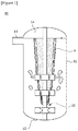
- FIG. 2 is a conceptual diagram showing an apparatus (100) for producing a polymer latex resin powder (hereinafter, also referred to as a 'production apparatus') related to one example of the present invention.
- Figure 3 is a diagram for explaining a connection structure of a discharge line
- Figure 4 is an analysis result of Area A in Figure 3 .
- the production apparatus (100) comprises a first flocculation tank (110), a plurality of supply lines (111, 112), a stirring part (120) and a discharge line (130).
- the production apparatus (100) comprises a first flocculation tank (110) to which a polymer latex and a flocculant are each supplied. Also, the first flocculation tank (110) is provided with a stirring part (120) including a rotation axis (121) and one or more impellers (122) mounted on the rotation axis (121), and a discharge line (130), respectively. In addition, the first flocculation tank (110) is provided so as to operate in a closed system when the stirring part (120) is operated.
- the first flocculation tank (110) may be composed of a flocculation tank operated in a closed system.
- the unexplained symbol C denotes the central axis of the first flocculation tank (110).
- the fact that the first flocculation tank (110) operates in a closed system means that the first flocculation tank (110) and the discharge line (130) are fully filled with the polymer slurry upon operating the stirring part (120).
- the fact that the first flocculation tank (110) operates in a closed system may also mean that 90% or more of the volume of the first flocculation tank (110) is filled with the polymer slurry, preferably, may also mean that 95% or more of the volume of the first flocculation tank (110) is filled with the polymer slurry, and more preferably, may mean that 100% of the volume of the first flocculation tank (110) is filled with the polymer slurry.
- a supply part (102) may be provided in the bottom region.
- a first and second supply lines (111, 112), to which a polymer latex and a flocculant are each supplied, may be connected to the bottom region.
- Each of the supply lines (111, 112) may be connected to one or more supply sources (101).
- the supply source may comprise, for example, a latex tank.
- water or the like may be further supplied to the first flocculation tank (110).
- first and second supply lines (111, 112) may be connected to the bottom region of the first flocculation tank (110), respectively. Also, the first and second supply lines (111, 112) may be connected to the bottom region of the first flocculation tank (110) in parallel to the axial direction of the rotation axis (121), respectively. Furthermore, the first and second supply lines (111, 112) may be provided so that the polymer latex and the flocculant are each supplied to the end side of the impeller (122) (the impeller positioned at the bottom region of the first flocculation tank).
- the discharge line (130) is connected to the top region of the first flocculation tank (110).
- the discharge line (130) is connected to the top region of the first flocculation tank (110), whereby the first flocculation tank (110) can easily operate in a closed system.
- the discharge line (130) of the first flocculation tank (110) may comprise a first region (131) connected to the first flocculation tank (110) and a second region (132) connected to the second flocculation tank (200). At this time, the first region (131) and the second region (132) may be connected at a predetermined angle.
- the boundary (133, connection) between the first region and the second region is located above the uppermost end (T) of the first flocculation tank (110).
- the boundary (133) between the first region and the second region is located above the uppermost end (T) of the first flocculating tank (110) based on the central axis (C) direction (y-axis direction) of the first flocculation tank.
- the first region (131) of the discharge line (130) when the first region (131) of the discharge line (130) is filled with the polymer slurry, 90% or more of the volume of the first flocculation tank (110) may be filled with the polymer slurry, preferably, 95% or more of the volume of the first flocculation tank (110) may be filled with the polymer slurry, and more preferably, 100% of the first flocculation tank (110) may be filled with the polymer slurry.
- the discharge line (130) is connected to the first flocculation tank (110) along the tangential direction.
- the first flocculation tank (110) may be in the form of a cylindrical cylinder.
- the first flocculation tank (110) may have a circular cross-section shape parallel to the x-axis direction in Figure 2 .
- the first region (131) is connected to the first flocculation tank (110) along the tangential direction.
- the tangential direction means that it is connected to the tangential direction of the first flocculation tank (110) based on the center axis (C) of the first flocculation tank (110).
- the discharge line (130) is connected to the first flocculation tank (110) so as to be inclined at a predetermined angle based on the rotation axis (121) of the stirring part (120) (or the central axis of the first flocculation tank).
- the first region (131) is connected to the first flocculation tank (110) so as to be inclined at a predetermined angle based on the rotation axis (121) of the stirring part (120) (or the central axis of the first flocculation tank).
- the angle ( ⁇ ) is about 45° so that the flow of the polymer slurry can be performed in a state where the polymer slurry is filled in the discharge line (130).
- the discharge line (130) is connected to the first flocculation tank (110) in a state of being inclined at a predetermined angle, the outlet flow rate can be maintained constant.
- the production apparatus (100) may further comprise a second flocculation tank (200) into which the polymer slurry discharged from the first flocculation tank (110) flows.
- the second flocculation tank (200) may have the general flocculation tank structure described through Figure 1 .
- the second flocculation tank (200) may comprise a housing (210) providing a stirring space, a stirring part (220) provided in the housing (210) and a discharge line (213) connected to the housing (210).
- the second flocculation tank (200) may be provided so as to operate in an open system.
- the discharge line (130) of the first flocculation tank (110) may be connected at a height lower than the slurry level (L) of the second flocculation tank (200).
- the first flocculation tank (110) and the discharge line (130) may be fully filled with the polymer slurry when the stirring part (120) is operated.
- Figure 5 is a conceptual diagram showing an apparatus for producing a polymer latex resin powder related to another example of the present invention.
- the apparatus for producing a polymer latex resin powder may comprise a plurality of first flocculation tanks (110, 110'). Also, two adjacent first flocculation tanks (110, 110') may be connected together to form a closed system.
- the discharge line (130) of the first flocculation tank (110) connected to the supply source (101) is connected to the supply part (102') of the adjacent first flocculation tank (110').
- the first region (131) is drawn out from the top region of the first flocculation tank (110)
- the second region (132) is connected to the supply part (102') of the bottom region of the adjacent first flocculation tank (110').
- a method for producing a polymer latex resin powder (hereinafter, also referred to as a 'production method') using the production apparatus (100) having such a structure will be described in detail.
- the production method comprises steps of supplying a polymer latex and a flocculant to a first flocculation tank (110), respectively, stirring the polymer latex and the flocculant in the first flocculation tank (110) in a closed system, and supplying the polymer slurry in the first flocculation tank to a second flocculation tank (200).
- the polymer slurry in the first flocculation tank (110) is supplied at a height lower than the slurry level (L) of the second flocculation tank (200).
- the first flocculation tank (110) is filled with the polymer slurry at the time of stirring.
- Figure 6 is a graph showing the distribution ratio of the shear rate.
- a reference symbol E1 denotes existing coagulation
- a reference symbol E2 denotes new coagulation.
- the 'existing coagulation' represents the distribution ratio of the shear rate in the flocculation tank operating in the open system described in Figure 1
- the 'new coagulation' is the result using the production apparatus related to the present invention, which represents the distribution ratio of the shear rate in the flocculation tank operating in the closed system, and it can be confirmed that the distribution ratio of the shear rate is uniformly formed when the flocculation tank is operated in the closed system.
- the flocculation tank as the flocculation tank is provided so as to operate in a closed system upon stirring the polymer slurry, the fine and coarse particles can be reduced and the uniform shear force can be applied to the polymer slurry through the stirring part.
Landscapes
- Chemical & Material Sciences (AREA)
- Chemical Kinetics & Catalysis (AREA)
- Organic Chemistry (AREA)
- Health & Medical Sciences (AREA)
- Medicinal Chemistry (AREA)
- Polymers & Plastics (AREA)
- Dispersion Chemistry (AREA)
- Processes Of Treating Macromolecular Substances (AREA)
- Addition Polymer Or Copolymer, Post-Treatments, Or Chemical Modifications (AREA)
- Processing And Handling Of Plastics And Other Materials For Molding In General (AREA)
Abstract
Description
- The present invention relates to an apparatus and a method for producing a polymer latex resin powder.
- This application claims the benefit of priority based on Korean Patent Application No.
10-2017-0147939 filed on November 8, 2017 10-2018-0128632 filed on October 26, 2018 - Generally, slow coagulation is used as a method for preparing a polymer latex as a powder in an emulsion polymerization process, and in this method, an aqueous solution of a flocculant such as an inorganic salt and an acid is divided in small amounts and added to break stability of an emulsifier, whereby the polymer in the latex is agglomerated.
- The slow coagulation method is capable of controlling the particle size as compared with a rapid coagulation method. A process of agglomerating polymer particles in the latex is called coagulation and one in which the polymer particles are agglomerated is called a slurry, where they are in a physically weakly bonded state, and thus show an easy break-up phenomenon by shear force by a stirrer (for example, an impeller).
- In addition, the primarily coagulated slurry is subjected to an aging process. The slurry thus generated is subjected to dehydrating and drying processes to finally obtain a powdery phase.
- Usually, in the polymer latex resin powder, fine particles having an average particle diameter of about 75µm or less are called "fine" particles and larger particles having an average particle diameter of about 800µm or more are called "coarse" particles. The fine particles deteriorate the performance of the dehydrator and the dryer of the latex resin powder and are easily scattered into the air, which cause many problems in transport and packing of the powder in the process, and the coarse particles have a problem of transport and storage and have a disadvantage that compatibility with other polymer resins is poor.
-
Figure 1 is a conceptual diagram showing a conventional apparatus (10) for producing a polymer latex resin powder. - Referring to
Figure 1 , the production apparatus (10) comprises a flocculation tank (11), a plurality of supply lines (12) for supplying a polymer latex, a flocculant and water, and the like into the flocculation tank, a stirring part (20) provided in the flocculation tank (11) and a discharge line (13). Here, the flocculation tank (11) has been provided so as to operate in an open system. Specifically, the flocculation tank (11) is maintained at a predetermined slurry level, and an air layer (14) is formed on the top of the flocculation tank (11). - As described above, when the stirring part (20) is operated in the open system, coarse particles are generated by formation of vortexes (V) around the stirring part (20).
- It is an object of the present invention to provide an apparatus and a method for producing a polymer latex resin powder capable of reducing fine and coarse particles.
- It is another object of the present invention to provide an apparatus and a method for producing a polymer latex resin powder capable of applying uniform shear force.
- To solve the above-described objects, according to one aspect of the present invention, there is provided an apparatus for producing a polymer latex resin powder comprising a first flocculation tank to which a polymer latex and a flocculant are each supplied, wherein the first flocculation tank is provided with a stirring part including a rotation axis and one or more impellers mounted on the rotation axis, and a discharge line, respectively and the first flocculation tank is provided so as to operate in a closed system upon operating the stirring part.
- The discharge line is connected to the top region of the first flocculation tank, whereby the first flocculation tank is provided so as to operate in a closed system upon operating the stirring part.
- Also, the discharge line is connected along the tangential direction to the first flocculation tank.
- Furthermore, the discharge line is connected to the first flocculation tank so as to be inclined at a predetermined angle based on the rotation axis of the stirring part. In addition, the angle may be 45°.
- Also, first and second supply lines, to which the polymer latex and the flocculant are each supplied, may be connected to the first flocculation tank.
- Furthermore, the first and second supply lines may be each connected to the bottom region of the first flocculation tank and may be provided so that the polymer latex and the flocculant are each supplied to the end side of the impeller.
- In addition, the apparatus for producing a polymer latex resin powder may further comprise a second flocculation tank into which the polymer slurry discharged from the first flocculation tank flows.
- At this time, the discharge line may be connected to the second flocculation tank at a height lower than the slurry level of the second flocculation tank.
- Also, the discharge line may comprise a first region connected to the first flocculation tank and a second region connected to the second flocculation tank.
- Furthermore, the boundary between the first region and the second region may be located above the uppermost end of the first flocculation tank.
- In addition, the first region and the second region of the discharge line may be connected at a predetermined angle.
- Also, it is preferable that both the first flocculation tank and the discharge line are each filled with the polymer slurry upon operating the stirring part.
- In addition, according to another aspect of the present invention, there is provided a method for producing a polymer latex resin powder, comprising steps of supplying a polymer latex and a flocculant to a first flocculation tank, stirring the polymer latex and flocculant in the first flocculation tank in a closed system and supplying the polymer slurry in the first flocculation tank into a second flocculation tank.
- As described above, the apparatus and method for producing a polymer latex resin powder related to at least one example of the present invention have the following effects.
- As the flocculation tank is provided so as to operate in a closed system upon stirring the polymer slurry, the fine and coarse particles can be reduced and the uniform shear force can be applied to the polymer slurry through the stirring part.
-
-
Figure 1 is a conceptual diagram showing a conventional apparatus for producing a polymer latex resin powder. -
Figure 2 is a conceptual diagram showing an apparatus for producing a polymer latex resin powder related to one example of the present invention. -
Figure 3 is a diagram for explaining a connection structure of a discharge line. -
Figure 4 shows an analysis result of Area A inFigure 3 . -
Figure 5 is a conceptual diagram showing an apparatus for producing a polymer latex resin powder related to another example of the present invention. -
Figure 6 is a graph showing the distribution ratio of the shear rate. - Hereinafter, an apparatus and a method for producing a polymer latex resin powder according to one example of the present invention will be described in detail with reference to the accompanying drawings.
- In addition, the same or similar reference numerals are given to the same or corresponding components regardless of reference numerals, of which redundant explanations will be omitted, and for convenience of explanation, the size and shape of each constituent member as shown may be exaggerated or reduced.
-
Figure 2 is a conceptual diagram showing an apparatus (100) for producing a polymer latex resin powder (hereinafter, also referred to as a 'production apparatus') related to one example of the present invention. - Also,
Figure 3 is a diagram for explaining a connection structure of a discharge line, andFigure 4 is an analysis result of Area A inFigure 3 . - The production apparatus (100) comprises a first flocculation tank (110), a plurality of supply lines (111, 112), a stirring part (120) and a discharge line (130).
- Specifically, the production apparatus (100) comprises a first flocculation tank (110) to which a polymer latex and a flocculant are each supplied. Also, the first flocculation tank (110) is provided with a stirring part (120) including a rotation axis (121) and one or more impellers (122) mounted on the rotation axis (121), and a discharge line (130), respectively. In addition, the first flocculation tank (110) is provided so as to operate in a closed system when the stirring part (120) is operated. The first flocculation tank (110) may be composed of a flocculation tank operated in a closed system. The unexplained symbol C denotes the central axis of the first flocculation tank (110).
- In this document, the fact that the first flocculation tank (110) operates in a closed system means that the first flocculation tank (110) and the discharge line (130) are fully filled with the polymer slurry upon operating the stirring part (120). For example, the fact that the first flocculation tank (110) operates in a closed system may also mean that 90% or more of the volume of the first flocculation tank (110) is filled with the polymer slurry, preferably, may also mean that 95% or more of the volume of the first flocculation tank (110) is filled with the polymer slurry, and more preferably, may mean that 100% of the volume of the first flocculation tank (110) is filled with the polymer slurry.
- In addition, in the first flocculation tank (110), a supply part (102) may be provided in the bottom region. Specifically, in the first flocculation tank (110), a first and second supply lines (111, 112), to which a polymer latex and a flocculant are each supplied, may be connected to the bottom region. Each of the supply lines (111, 112) may be connected to one or more supply sources (101). The supply source may comprise, for example, a latex tank. Furthermore, water or the like may be further supplied to the first flocculation tank (110).
- On the other hand, the first and second supply lines (111, 112) may be connected to the bottom region of the first flocculation tank (110), respectively. Also, the first and second supply lines (111, 112) may be connected to the bottom region of the first flocculation tank (110) in parallel to the axial direction of the rotation axis (121), respectively. Furthermore, the first and second supply lines (111, 112) may be provided so that the polymer latex and the flocculant are each supplied to the end side of the impeller (122) (the impeller positioned at the bottom region of the first flocculation tank).
- The discharge line (130) is connected to the top region of the first flocculation tank (110). The discharge line (130) is connected to the top region of the first flocculation tank (110), whereby the first flocculation tank (110) can easily operate in a closed system.
- Also, the discharge line (130) of the first flocculation tank (110) may comprise a first region (131) connected to the first flocculation tank (110) and a second region (132) connected to the second flocculation tank (200). At this time, the first region (131) and the second region (132) may be connected at a predetermined angle.
- In addition, the boundary (133, connection) between the first region and the second region is located above the uppermost end (T) of the first flocculation tank (110). In this document, the boundary (133) between the first region and the second region is located above the uppermost end (T) of the first flocculating tank (110) based on the central axis (C) direction (y-axis direction) of the first flocculation tank. In this structure, when the first region (131) of the discharge line (130) is filled with the polymer slurry, 90% or more of the volume of the first flocculation tank (110) may be filled with the polymer slurry, preferably, 95% or more of the volume of the first flocculation tank (110) may be filled with the polymer slurry, and more preferably, 100% of the first flocculation tank (110) may be filled with the polymer slurry.
- Referring to
Figure 3 , the discharge line (130) is connected to the first flocculation tank (110) along the tangential direction. The first flocculation tank (110) may be in the form of a cylindrical cylinder. The first flocculation tank (110) may have a circular cross-section shape parallel to the x-axis direction inFigure 2 . In this structure, the first region (131) is connected to the first flocculation tank (110) along the tangential direction. The tangential direction means that it is connected to the tangential direction of the first flocculation tank (110) based on the center axis (C) of the first flocculation tank (110). - Also, the discharge line (130) is connected to the first flocculation tank (110) so as to be inclined at a predetermined angle based on the rotation axis (121) of the stirring part (120) (or the central axis of the first flocculation tank). Specifically, the first region (131) is connected to the first flocculation tank (110) so as to be inclined at a predetermined angle based on the rotation axis (121) of the stirring part (120) (or the central axis of the first flocculation tank).
- Furthermore, it is preferable that the angle (θ) is about 45° so that the flow of the polymer slurry can be performed in a state where the polymer slurry is filled in the discharge line (130). In addition, when the discharge line (130) is connected to the first flocculation tank (110) in a state of being inclined at a predetermined angle, the outlet flow rate can be maintained constant.
- In addition, the production apparatus (100) may further comprise a second flocculation tank (200) into which the polymer slurry discharged from the first flocculation tank (110) flows.
- At this time, the second flocculation tank (200) may have the general flocculation tank structure described through
Figure 1 . For example, the second flocculation tank (200) may comprise a housing (210) providing a stirring space, a stirring part (220) provided in the housing (210) and a discharge line (213) connected to the housing (210). In addition, the second flocculation tank (200) may be provided so as to operate in an open system. - On the other hand, the discharge line (130) of the first flocculation tank (110) may be connected at a height lower than the slurry level (L) of the second flocculation tank (200).
- In such a structure, the first flocculation tank (110) and the discharge line (130) may be fully filled with the polymer slurry when the stirring part (120) is operated.
-
Figure 5 is a conceptual diagram showing an apparatus for producing a polymer latex resin powder related to another example of the present invention. - Referring to
Figure 5 , the apparatus for producing a polymer latex resin powder may comprise a plurality of first flocculation tanks (110, 110'). Also, two adjacent first flocculation tanks (110, 110') may be connected together to form a closed system. - For example, the discharge line (130) of the first flocculation tank (110) connected to the supply source (101) is connected to the supply part (102') of the adjacent first flocculation tank (110'). At this time, in the discharge line (130) of the first flocculation tank (100) connected to the supply source (101), the first region (131) is drawn out from the top region of the first flocculation tank (110), and the second region (132) is connected to the supply part (102') of the bottom region of the adjacent first flocculation tank (110').
- A method for producing a polymer latex resin powder (hereinafter, also referred to as a 'production method') using the production apparatus (100) having such a structure will be described in detail.
- The production method comprises steps of supplying a polymer latex and a flocculant to a first flocculation tank (110), respectively, stirring the polymer latex and the flocculant in the first flocculation tank (110) in a closed system, and supplying the polymer slurry in the first flocculation tank to a second flocculation tank (200).
- Also, it is preferable that the polymer slurry in the first flocculation tank (110) is supplied at a height lower than the slurry level (L) of the second flocculation tank (200).
- In addition, it is preferable that the first flocculation tank (110) is filled with the polymer slurry at the time of stirring.
-
Figure 6 is a graph showing the distribution ratio of the shear rate. - Referring to
Figure 6 , a reference symbol E1 denotes existing coagulation, and a reference symbol E2 denotes new coagulation. At this time, the 'existing coagulation' represents the distribution ratio of the shear rate in the flocculation tank operating in the open system described inFigure 1 , and the 'new coagulation' is the result using the production apparatus related to the present invention, which represents the distribution ratio of the shear rate in the flocculation tank operating in the closed system, and it can be confirmed that the distribution ratio of the shear rate is uniformly formed when the flocculation tank is operated in the closed system. - The preferred examples of the present invention as described above are disclosed for illustrative purposes, which can be modified, changed and added within thought and scope of the present invention by those skilled in the art and it will be considered that such modification, change and addition fall within the following claims.
- According to the apparatus and method for producing a polymer latex resin powder related to at least one example of the present invention, as the flocculation tank is provided so as to operate in a closed system upon stirring the polymer slurry, the fine and coarse particles can be reduced and the uniform shear force can be applied to the polymer slurry through the stirring part.
Claims (7)
- An apparatus for producing a polymer latex resin powder comprising a first flocculation tank to which a polymer latex and a flocculant are each supplied,
wherein the first flocculation tank is provided with a stirring part including a rotation axis and one or more impellers mounted on the rotation axis, and a discharge line, respectively,
the discharge line is connected to the top region of the first flocculation tank,
the first flocculation tank is provided so as to operate in a closed system upon operating the stirring part, and
the discharge line is connected along the tangential direction to the first flocculation tank, and connected to the first flocculation tank so as to be inclined at a predetermined angle based on the rotation axis of the stirring part. - The apparatus for producing a polymer latex resin powder according to claim 1,
wherein first and second supply lines, to which the polymer latex and the flocculant are each supplied, are connected to the first flocculation tank, and
the first and second supply lines are each connected to the bottom region of the first flocculation tank and provided so that the polymer latex and the flocculant are each supplied to the end side of the impeller. - The apparatus for producing a polymer latex resin powder according to claim 1, wherein the angle is 45°.
- The apparatus for producing a polymer latex resin powder according to claim 1, further comprising a second flocculation tank into which the polymer slurry discharged from the first flocculation tank flows,
wherein the discharge line is connected to the second flocculation tank at a height lower than the slurry level of the second flocculation tank. - The apparatus for producing a polymer latex resin powder according to claim 4,
wherein the discharge line comprises a first region connected to the first flocculation tank and a second region connected to the second flocculation tank, and
the first region and the second region are connected at a predetermined angle. - The apparatus for producing a polymer latex resin powder according to claim 5,
wherein the boundary between the first region and the second region is located above the uppermost end of the first flocculation tank. - The apparatus for producing a polymer latex resin powder according to claim 4,
wherein both the first flocculation tank and the discharge line are filled with the polymer slurry upon operating the stirring part.
Applications Claiming Priority (3)
| Application Number | Priority Date | Filing Date | Title |
|---|---|---|---|
| KR20170147939 | 2017-11-08 | ||
| KR1020180128632A KR102290712B1 (en) | 2017-11-08 | 2018-10-26 | Apparatus and method for preparing of polymer latex |
| PCT/KR2018/013144 WO2019093712A1 (en) | 2017-11-08 | 2018-11-01 | Apparatus and method for preparing polymer latex resin powder |
Publications (3)
| Publication Number | Publication Date |
|---|---|
| EP3708248A1 true EP3708248A1 (en) | 2020-09-16 |
| EP3708248A4 EP3708248A4 (en) | 2020-09-16 |
| EP3708248B1 EP3708248B1 (en) | 2024-07-10 |
Family
ID=66672053
Family Applications (1)
| Application Number | Title | Priority Date | Filing Date |
|---|---|---|---|
| EP18875077.2A Active EP3708248B1 (en) | 2017-11-08 | 2018-11-01 | Method for preparing polymer latex resin powder |
Country Status (5)
| Country | Link |
|---|---|
| US (1) | US12043707B2 (en) |
| EP (1) | EP3708248B1 (en) |
| JP (1) | JP6952893B2 (en) |
| KR (1) | KR102290712B1 (en) |
| CN (1) | CN111225738B (en) |
Cited By (1)
| Publication number | Priority date | Publication date | Assignee | Title |
|---|---|---|---|---|
| US11353037B2 (en) | 2016-11-15 | 2022-06-07 | Gardner Denver Deutschland Gmbh | Side channel compressor having a seal assembly |
Families Citing this family (2)
| Publication number | Priority date | Publication date | Assignee | Title |
|---|---|---|---|---|
| CN112142881B (en) * | 2020-10-21 | 2024-05-03 | 辽宁金发科技有限公司 | Method for agglomerating ABS grafted latex and device used by same |
| CN113774772B (en) * | 2020-12-24 | 2024-08-20 | 安徽丰林建设工程有限公司 | Road repair protection equipment |
Family Cites Families (16)
| Publication number | Priority date | Publication date | Assignee | Title |
|---|---|---|---|---|
| US2491519A (en) | 1945-05-25 | 1949-12-20 | Standard Oil Dev Co | Coagulation of butadiene-acrylo-nitrile copolymers |
| US2495147A (en) | 1946-06-18 | 1950-01-17 | Firestone Tire & Rubber Co | Coagulation process and apparatus |
| JPS5798503A (en) | 1980-12-09 | 1982-06-18 | Japan Synthetic Rubber Co Ltd | Method for coagulating thermoplastic resin latex |
| JP3313026B2 (en) * | 1995-07-04 | 2002-08-12 | 三菱レイヨン株式会社 | Method for coagulating and enlarging diene-based polymer rubber latex, graft polymer and thermoplastic resin composition |
| JP2000239315A (en) | 1999-02-16 | 2000-09-05 | Mitsubishi Rayon Co Ltd | Method for producing polymer |
| DE19953301A1 (en) | 1999-11-05 | 2001-05-10 | Bayer Ag | Solid particles |
| KR100385725B1 (en) | 2001-01-04 | 2003-05-27 | 주식회사 엘지화학 | Multi-stage process for continuous coagulation |
| KR100428638B1 (en) * | 2001-09-13 | 2004-04-30 | 주식회사 엘지화학 | Method for preparing of high macromolecule latex resin powder |
| WO2005077985A2 (en) | 2004-02-13 | 2005-08-25 | Total Petrochemicals Research Feluy | Multiple loop reactor for olefin polymerization |
| KR20070004784A (en) | 2004-03-08 | 2007-01-09 | 카네카 코포레이션 | Process for producing emulsion polymerized latex aggregated particles |
| JP2006045292A (en) * | 2004-08-02 | 2006-02-16 | Kaneka Corp | Method for producing rubbery polymer particle and method for producing resin composition containing the same |
| KR100684424B1 (en) * | 2004-10-19 | 2007-02-16 | 주식회사 엘지화학 | Method for preparing polymer latex resin powder using normal pressure slow flocculation-pressurizing aging process |
| KR101168401B1 (en) | 2008-09-22 | 2012-07-25 | 주식회사 엘지화학 | Method of manufacturing high molecule latex resin powder and the powder manufactured by using the method |
| JP5843071B2 (en) * | 2010-03-30 | 2016-01-13 | 栗田工業株式会社 | Water treatment equipment |
| US9028730B2 (en) | 2013-03-15 | 2015-05-12 | Purolite Corporation | Method of producing uniform polymer beads of various sizes |
| KR102096273B1 (en) | 2016-08-26 | 2020-04-02 | 주식회사 엘지화학 | Apparatus and method for preparing of polymer latex |
-
2018
- 2018-10-26 KR KR1020180128632A patent/KR102290712B1/en active Active
- 2018-11-01 JP JP2020520064A patent/JP6952893B2/en active Active
- 2018-11-01 US US16/754,950 patent/US12043707B2/en active Active
- 2018-11-01 EP EP18875077.2A patent/EP3708248B1/en active Active
- 2018-11-01 CN CN201880065596.XA patent/CN111225738B/en active Active
Cited By (1)
| Publication number | Priority date | Publication date | Assignee | Title |
|---|---|---|---|---|
| US11353037B2 (en) | 2016-11-15 | 2022-06-07 | Gardner Denver Deutschland Gmbh | Side channel compressor having a seal assembly |
Also Published As
| Publication number | Publication date |
|---|---|
| KR20190052613A (en) | 2019-05-16 |
| JP6952893B2 (en) | 2021-10-27 |
| US12043707B2 (en) | 2024-07-23 |
| CN111225738A (en) | 2020-06-02 |
| KR102290712B1 (en) | 2021-08-19 |
| JP2021501065A (en) | 2021-01-14 |
| EP3708248B1 (en) | 2024-07-10 |
| CN111225738B (en) | 2022-04-08 |
| US20200230525A1 (en) | 2020-07-23 |
| EP3708248A4 (en) | 2020-09-16 |
Similar Documents
| Publication | Publication Date | Title |
|---|---|---|
| US10369535B2 (en) | Rapid stirring machine | |
| EP3708248B1 (en) | Method for preparing polymer latex resin powder | |
| CN107851773B (en) | Battery electrode slurry distribution device, battery electrode slurry treatment device, battery electrode slurry distribution method, suspension distribution device, suspension distribution method | |
| CN102481535B (en) | Polymer-latex-resin-powder producing device, and a method for producing a polymer latex resin powder employing the same | |
| AU2013280162B2 (en) | Dispersion and conditioning techniques for thick fine tailings dewatering operations | |
| US10626227B2 (en) | Method of preparing resin powder and integrated coagulator for the same | |
| KR102096273B1 (en) | Apparatus and method for preparing of polymer latex | |
| US5747640A (en) | Continunous process for preparing polytetrafluoroethlene wet powder | |
| JP5905994B2 (en) | Polymer latex resin powder production apparatus and polymer latex resin powder production method using the same | |
| CN107840425B (en) | a flocculation tank | |
| Özcan‐Taşkın | Dispersion of fine powders in liquids: Particle incorporation and size reduction | |
| KR101711243B1 (en) | Method and apparatus for preparing resin powders | |
| CN113164894B (en) | Method for providing a homogeneous slurry containing particles | |
| CN103539282B (en) | Water treatment apparatus with circulating flow path and water treatment method using the same | |
| KR101785767B1 (en) | Apparatus for preparing polymer latex resin powder and manufacturing method of polymer latex resin powder using the same | |
| JP6961199B2 (en) | Muddy water treatment equipment and muddy water treatment method | |
| SE537737C2 (en) | In-Line Preparation of Silica for Retention Purposes in Paper or Cardboard Manufacturing Process | |
| WO2009053530A1 (en) | A pulp container and a method for discharging pulp from a pulp container |
Legal Events
| Date | Code | Title | Description |
|---|---|---|---|
| STAA | Information on the status of an ep patent application or granted ep patent |
Free format text: STATUS: THE INTERNATIONAL PUBLICATION HAS BEEN MADE |
|
| PUAI | Public reference made under article 153(3) epc to a published international application that has entered the european phase |
Free format text: ORIGINAL CODE: 0009012 |
|
| STAA | Information on the status of an ep patent application or granted ep patent |
Free format text: STATUS: REQUEST FOR EXAMINATION WAS MADE |
|
| 17P | Request for examination filed |
Effective date: 20200407 |
|
| A4 | Supplementary search report drawn up and despatched |
Effective date: 20200714 |
|
| AK | Designated contracting states |
Kind code of ref document: A1 Designated state(s): AL AT BE BG CH CY CZ DE DK EE ES FI FR GB GR HR HU IE IS IT LI LT LU LV MC MK MT NL NO PL PT RO RS SE SI SK SM TR |
|
| AX | Request for extension of the european patent |
Extension state: BA ME |
|
| DAV | Request for validation of the european patent (deleted) | ||
| DAX | Request for extension of the european patent (deleted) | ||
| STAA | Information on the status of an ep patent application or granted ep patent |
Free format text: STATUS: EXAMINATION IS IN PROGRESS |
|
| 17Q | First examination report despatched |
Effective date: 20220322 |
|
| REG | Reference to a national code |
Ref country code: DE Ref legal event code: R079 Ipc: B01F0027700000 Ref country code: DE Ref legal event code: R079 Ref document number: 602018071700 Country of ref document: DE Free format text: PREVIOUS MAIN CLASS: B01J0002100000 Ipc: B01F0027700000 |
|
| GRAP | Despatch of communication of intention to grant a patent |
Free format text: ORIGINAL CODE: EPIDOSNIGR1 |
|
| STAA | Information on the status of an ep patent application or granted ep patent |
Free format text: STATUS: GRANT OF PATENT IS INTENDED |
|
| RIC1 | Information provided on ipc code assigned before grant |
Ipc: B01F 27/70 20220101AFI20240315BHEP |
|
| INTG | Intention to grant announced |
Effective date: 20240419 |
|
| GRAS | Grant fee paid |
Free format text: ORIGINAL CODE: EPIDOSNIGR3 |
|
| GRAA | (expected) grant |
Free format text: ORIGINAL CODE: 0009210 |
|
| STAA | Information on the status of an ep patent application or granted ep patent |
Free format text: STATUS: THE PATENT HAS BEEN GRANTED |
|
| AK | Designated contracting states |
Kind code of ref document: B1 Designated state(s): AL AT BE BG CH CY CZ DE DK EE ES FI FR GB GR HR HU IE IS IT LI LT LU LV MC MK MT NL NO PL PT RO RS SE SI SK SM TR |
|
| REG | Reference to a national code |
Ref country code: CH Ref legal event code: EP |
|
| REG | Reference to a national code |
Ref country code: DE Ref legal event code: R096 Ref document number: 602018071700 Country of ref document: DE |
|
| REG | Reference to a national code |
Ref country code: LT Ref legal event code: MG9D |
|
| REG | Reference to a national code |
Ref country code: NL Ref legal event code: MP Effective date: 20240710 |
|
| PG25 | Lapsed in a contracting state [announced via postgrant information from national office to epo] |
Ref country code: PT Free format text: LAPSE BECAUSE OF FAILURE TO SUBMIT A TRANSLATION OF THE DESCRIPTION OR TO PAY THE FEE WITHIN THE PRESCRIBED TIME-LIMIT Effective date: 20241111 |
|
| REG | Reference to a national code |
Ref country code: AT Ref legal event code: MK05 Ref document number: 1701581 Country of ref document: AT Kind code of ref document: T Effective date: 20240710 |
|
| PG25 | Lapsed in a contracting state [announced via postgrant information from national office to epo] |
Ref country code: NL Free format text: LAPSE BECAUSE OF FAILURE TO SUBMIT A TRANSLATION OF THE DESCRIPTION OR TO PAY THE FEE WITHIN THE PRESCRIBED TIME-LIMIT Effective date: 20240710 |
|
| PG25 | Lapsed in a contracting state [announced via postgrant information from national office to epo] |
Ref country code: PT Free format text: LAPSE BECAUSE OF FAILURE TO SUBMIT A TRANSLATION OF THE DESCRIPTION OR TO PAY THE FEE WITHIN THE PRESCRIBED TIME-LIMIT Effective date: 20241111 Ref country code: NL Free format text: LAPSE BECAUSE OF FAILURE TO SUBMIT A TRANSLATION OF THE DESCRIPTION OR TO PAY THE FEE WITHIN THE PRESCRIBED TIME-LIMIT Effective date: 20240710 |
|
| PG25 | Lapsed in a contracting state [announced via postgrant information from national office to epo] |
Ref country code: NO Free format text: LAPSE BECAUSE OF FAILURE TO SUBMIT A TRANSLATION OF THE DESCRIPTION OR TO PAY THE FEE WITHIN THE PRESCRIBED TIME-LIMIT Effective date: 20241010 |
|
| PG25 | Lapsed in a contracting state [announced via postgrant information from national office to epo] |
Ref country code: FI Free format text: LAPSE BECAUSE OF FAILURE TO SUBMIT A TRANSLATION OF THE DESCRIPTION OR TO PAY THE FEE WITHIN THE PRESCRIBED TIME-LIMIT Effective date: 20240710 Ref country code: GR Free format text: LAPSE BECAUSE OF FAILURE TO SUBMIT A TRANSLATION OF THE DESCRIPTION OR TO PAY THE FEE WITHIN THE PRESCRIBED TIME-LIMIT Effective date: 20241011 Ref country code: PL Free format text: LAPSE BECAUSE OF FAILURE TO SUBMIT A TRANSLATION OF THE DESCRIPTION OR TO PAY THE FEE WITHIN THE PRESCRIBED TIME-LIMIT Effective date: 20240710 |
|
| PG25 | Lapsed in a contracting state [announced via postgrant information from national office to epo] |
Ref country code: BG Free format text: LAPSE BECAUSE OF FAILURE TO SUBMIT A TRANSLATION OF THE DESCRIPTION OR TO PAY THE FEE WITHIN THE PRESCRIBED TIME-LIMIT Effective date: 20240710 |
|
| PG25 | Lapsed in a contracting state [announced via postgrant information from national office to epo] |
Ref country code: LV Free format text: LAPSE BECAUSE OF FAILURE TO SUBMIT A TRANSLATION OF THE DESCRIPTION OR TO PAY THE FEE WITHIN THE PRESCRIBED TIME-LIMIT Effective date: 20240710 |
|
| PG25 | Lapsed in a contracting state [announced via postgrant information from national office to epo] |
Ref country code: IS Free format text: LAPSE BECAUSE OF FAILURE TO SUBMIT A TRANSLATION OF THE DESCRIPTION OR TO PAY THE FEE WITHIN THE PRESCRIBED TIME-LIMIT Effective date: 20241110 Ref country code: AT Free format text: LAPSE BECAUSE OF FAILURE TO SUBMIT A TRANSLATION OF THE DESCRIPTION OR TO PAY THE FEE WITHIN THE PRESCRIBED TIME-LIMIT Effective date: 20240710 |
|
| PG25 | Lapsed in a contracting state [announced via postgrant information from national office to epo] |
Ref country code: HR Free format text: LAPSE BECAUSE OF FAILURE TO SUBMIT A TRANSLATION OF THE DESCRIPTION OR TO PAY THE FEE WITHIN THE PRESCRIBED TIME-LIMIT Effective date: 20240710 |
|
| PG25 | Lapsed in a contracting state [announced via postgrant information from national office to epo] |
Ref country code: RS Free format text: LAPSE BECAUSE OF FAILURE TO SUBMIT A TRANSLATION OF THE DESCRIPTION OR TO PAY THE FEE WITHIN THE PRESCRIBED TIME-LIMIT Effective date: 20241010 Ref country code: ES Free format text: LAPSE BECAUSE OF FAILURE TO SUBMIT A TRANSLATION OF THE DESCRIPTION OR TO PAY THE FEE WITHIN THE PRESCRIBED TIME-LIMIT Effective date: 20240710 |
|
| PG25 | Lapsed in a contracting state [announced via postgrant information from national office to epo] |
Ref country code: RS Free format text: LAPSE BECAUSE OF FAILURE TO SUBMIT A TRANSLATION OF THE DESCRIPTION OR TO PAY THE FEE WITHIN THE PRESCRIBED TIME-LIMIT Effective date: 20241010 Ref country code: PL Free format text: LAPSE BECAUSE OF FAILURE TO SUBMIT A TRANSLATION OF THE DESCRIPTION OR TO PAY THE FEE WITHIN THE PRESCRIBED TIME-LIMIT Effective date: 20240710 Ref country code: NO Free format text: LAPSE BECAUSE OF FAILURE TO SUBMIT A TRANSLATION OF THE DESCRIPTION OR TO PAY THE FEE WITHIN THE PRESCRIBED TIME-LIMIT Effective date: 20241010 Ref country code: LV Free format text: LAPSE BECAUSE OF FAILURE TO SUBMIT A TRANSLATION OF THE DESCRIPTION OR TO PAY THE FEE WITHIN THE PRESCRIBED TIME-LIMIT Effective date: 20240710 Ref country code: IS Free format text: LAPSE BECAUSE OF FAILURE TO SUBMIT A TRANSLATION OF THE DESCRIPTION OR TO PAY THE FEE WITHIN THE PRESCRIBED TIME-LIMIT Effective date: 20241110 Ref country code: HR Free format text: LAPSE BECAUSE OF FAILURE TO SUBMIT A TRANSLATION OF THE DESCRIPTION OR TO PAY THE FEE WITHIN THE PRESCRIBED TIME-LIMIT Effective date: 20240710 Ref country code: GR Free format text: LAPSE BECAUSE OF FAILURE TO SUBMIT A TRANSLATION OF THE DESCRIPTION OR TO PAY THE FEE WITHIN THE PRESCRIBED TIME-LIMIT Effective date: 20241011 Ref country code: FI Free format text: LAPSE BECAUSE OF FAILURE TO SUBMIT A TRANSLATION OF THE DESCRIPTION OR TO PAY THE FEE WITHIN THE PRESCRIBED TIME-LIMIT Effective date: 20240710 Ref country code: ES Free format text: LAPSE BECAUSE OF FAILURE TO SUBMIT A TRANSLATION OF THE DESCRIPTION OR TO PAY THE FEE WITHIN THE PRESCRIBED TIME-LIMIT Effective date: 20240710 Ref country code: BG Free format text: LAPSE BECAUSE OF FAILURE TO SUBMIT A TRANSLATION OF THE DESCRIPTION OR TO PAY THE FEE WITHIN THE PRESCRIBED TIME-LIMIT Effective date: 20240710 Ref country code: AT Free format text: LAPSE BECAUSE OF FAILURE TO SUBMIT A TRANSLATION OF THE DESCRIPTION OR TO PAY THE FEE WITHIN THE PRESCRIBED TIME-LIMIT Effective date: 20240710 |
|
| REG | Reference to a national code |
Ref country code: DE Ref legal event code: R097 Ref document number: 602018071700 Country of ref document: DE |
|
| PG25 | Lapsed in a contracting state [announced via postgrant information from national office to epo] |
Ref country code: RO Free format text: LAPSE BECAUSE OF FAILURE TO SUBMIT A TRANSLATION OF THE DESCRIPTION OR TO PAY THE FEE WITHIN THE PRESCRIBED TIME-LIMIT Effective date: 20240710 Ref country code: SM Free format text: LAPSE BECAUSE OF FAILURE TO SUBMIT A TRANSLATION OF THE DESCRIPTION OR TO PAY THE FEE WITHIN THE PRESCRIBED TIME-LIMIT Effective date: 20240710 Ref country code: DK Free format text: LAPSE BECAUSE OF FAILURE TO SUBMIT A TRANSLATION OF THE DESCRIPTION OR TO PAY THE FEE WITHIN THE PRESCRIBED TIME-LIMIT Effective date: 20240710 |
|
| PG25 | Lapsed in a contracting state [announced via postgrant information from national office to epo] |
Ref country code: EE Free format text: LAPSE BECAUSE OF FAILURE TO SUBMIT A TRANSLATION OF THE DESCRIPTION OR TO PAY THE FEE WITHIN THE PRESCRIBED TIME-LIMIT Effective date: 20240710 |
|
| PG25 | Lapsed in a contracting state [announced via postgrant information from national office to epo] |
Ref country code: CZ Free format text: LAPSE BECAUSE OF FAILURE TO SUBMIT A TRANSLATION OF THE DESCRIPTION OR TO PAY THE FEE WITHIN THE PRESCRIBED TIME-LIMIT Effective date: 20240710 |
|
| PG25 | Lapsed in a contracting state [announced via postgrant information from national office to epo] |
Ref country code: IT Free format text: LAPSE BECAUSE OF FAILURE TO SUBMIT A TRANSLATION OF THE DESCRIPTION OR TO PAY THE FEE WITHIN THE PRESCRIBED TIME-LIMIT Effective date: 20240710 Ref country code: SK Free format text: LAPSE BECAUSE OF FAILURE TO SUBMIT A TRANSLATION OF THE DESCRIPTION OR TO PAY THE FEE WITHIN THE PRESCRIBED TIME-LIMIT Effective date: 20240710 |
|
| PLBE | No opposition filed within time limit |
Free format text: ORIGINAL CODE: 0009261 |
|
| STAA | Information on the status of an ep patent application or granted ep patent |
Free format text: STATUS: NO OPPOSITION FILED WITHIN TIME LIMIT |
|
| 26N | No opposition filed |
Effective date: 20250411 |
|
| REG | Reference to a national code |
Ref country code: CH Ref legal event code: PL |
|
| PG25 | Lapsed in a contracting state [announced via postgrant information from national office to epo] |
Ref country code: MC Free format text: LAPSE BECAUSE OF FAILURE TO SUBMIT A TRANSLATION OF THE DESCRIPTION OR TO PAY THE FEE WITHIN THE PRESCRIBED TIME-LIMIT Effective date: 20240710 |
|
| PG25 | Lapsed in a contracting state [announced via postgrant information from national office to epo] |
Ref country code: LU Free format text: LAPSE BECAUSE OF NON-PAYMENT OF DUE FEES Effective date: 20241101 |
|
| REG | Reference to a national code |
Ref country code: CH Ref legal event code: PL |
|
| PG25 | Lapsed in a contracting state [announced via postgrant information from national office to epo] |
Ref country code: CH Free format text: LAPSE BECAUSE OF NON-PAYMENT OF DUE FEES Effective date: 20241130 |
|
| REG | Reference to a national code |
Ref country code: BE Ref legal event code: MM Effective date: 20241130 |
|
| PG25 | Lapsed in a contracting state [announced via postgrant information from national office to epo] |
Ref country code: SE Free format text: LAPSE BECAUSE OF FAILURE TO SUBMIT A TRANSLATION OF THE DESCRIPTION OR TO PAY THE FEE WITHIN THE PRESCRIBED TIME-LIMIT Effective date: 20240710 |
|
| PG25 | Lapsed in a contracting state [announced via postgrant information from national office to epo] |
Ref country code: BE Free format text: LAPSE BECAUSE OF NON-PAYMENT OF DUE FEES Effective date: 20241130 |
|
| PG25 | Lapsed in a contracting state [announced via postgrant information from national office to epo] |
Ref country code: IE Free format text: LAPSE BECAUSE OF NON-PAYMENT OF DUE FEES Effective date: 20241101 |
|
| PGFP | Annual fee paid to national office [announced via postgrant information from national office to epo] |
Ref country code: DE Payment date: 20251020 Year of fee payment: 8 |
|
| PGFP | Annual fee paid to national office [announced via postgrant information from national office to epo] |
Ref country code: GB Payment date: 20251023 Year of fee payment: 8 |
|
| PGFP | Annual fee paid to national office [announced via postgrant information from national office to epo] |
Ref country code: FR Payment date: 20251021 Year of fee payment: 8 |
|
| PG25 | Lapsed in a contracting state [announced via postgrant information from national office to epo] |
Ref country code: HU Free format text: LAPSE BECAUSE OF FAILURE TO SUBMIT A TRANSLATION OF THE DESCRIPTION OR TO PAY THE FEE WITHIN THE PRESCRIBED TIME-LIMIT; INVALID AB INITIO Effective date: 20181101 |
|
| PG25 | Lapsed in a contracting state [announced via postgrant information from national office to epo] |
Ref country code: CY Free format text: LAPSE BECAUSE OF FAILURE TO SUBMIT A TRANSLATION OF THE DESCRIPTION OR TO PAY THE FEE WITHIN THE PRESCRIBED TIME-LIMIT; INVALID AB INITIO Effective date: 20181101 |