EP3708233A1 - Cover for oil filter housing of an integrated drive generator - Google Patents
Cover for oil filter housing of an integrated drive generator Download PDFInfo
- Publication number
- EP3708233A1 EP3708233A1 EP19215793.1A EP19215793A EP3708233A1 EP 3708233 A1 EP3708233 A1 EP 3708233A1 EP 19215793 A EP19215793 A EP 19215793A EP 3708233 A1 EP3708233 A1 EP 3708233A1
- Authority
- EP
- European Patent Office
- Prior art keywords
- cover
- end portion
- inches
- axial length
- axial
- Prior art date
- Legal status (The legal status is an assumption and is not a legal conclusion. Google has not performed a legal analysis and makes no representation as to the accuracy of the status listed.)
- Withdrawn
Links
- 230000004323 axial length Effects 0.000 claims abstract description 37
- 229910001250 2024 aluminium alloy Inorganic materials 0.000 claims description 5
- 229910000838 Al alloy Inorganic materials 0.000 claims 1
- 239000003921 oil Substances 0.000 description 26
- 238000012423 maintenance Methods 0.000 description 3
- 239000012530 fluid Substances 0.000 description 2
- 230000009286 beneficial effect Effects 0.000 description 1
- 230000015572 biosynthetic process Effects 0.000 description 1
- 238000001816 cooling Methods 0.000 description 1
- 230000003116 impacting effect Effects 0.000 description 1
- 238000009434 installation Methods 0.000 description 1
- 238000005461 lubrication Methods 0.000 description 1
- 239000000463 material Substances 0.000 description 1
- 238000012986 modification Methods 0.000 description 1
- 230000004048 modification Effects 0.000 description 1
- 239000002245 particle Substances 0.000 description 1
- 230000000737 periodic effect Effects 0.000 description 1
- 238000010248 power generation Methods 0.000 description 1
Images

Classifications
-
- B—PERFORMING OPERATIONS; TRANSPORTING
- B01—PHYSICAL OR CHEMICAL PROCESSES OR APPARATUS IN GENERAL
- B01D—SEPARATION
- B01D29/00—Filters with filtering elements stationary during filtration, e.g. pressure or suction filters, not covered by groups B01D24/00 - B01D27/00; Filtering elements therefor
- B01D29/11—Filters with filtering elements stationary during filtration, e.g. pressure or suction filters, not covered by groups B01D24/00 - B01D27/00; Filtering elements therefor with bag, cage, hose, tube, sleeve or like filtering elements
- B01D29/114—Filters with filtering elements stationary during filtration, e.g. pressure or suction filters, not covered by groups B01D24/00 - B01D27/00; Filtering elements therefor with bag, cage, hose, tube, sleeve or like filtering elements arranged for inward flow filtration
-
- F—MECHANICAL ENGINEERING; LIGHTING; HEATING; WEAPONS; BLASTING
- F01—MACHINES OR ENGINES IN GENERAL; ENGINE PLANTS IN GENERAL; STEAM ENGINES
- F01M—LUBRICATING OF MACHINES OR ENGINES IN GENERAL; LUBRICATING INTERNAL COMBUSTION ENGINES; CRANKCASE VENTILATING
- F01M11/00—Component parts, details or accessories, not provided for in, or of interest apart from, groups F01M1/00 - F01M9/00
- F01M11/03—Mounting or connecting of lubricant purifying means relative to the machine or engine; Details of lubricant purifying means
-
- F—MECHANICAL ENGINEERING; LIGHTING; HEATING; WEAPONS; BLASTING
- F16—ENGINEERING ELEMENTS AND UNITS; GENERAL MEASURES FOR PRODUCING AND MAINTAINING EFFECTIVE FUNCTIONING OF MACHINES OR INSTALLATIONS; THERMAL INSULATION IN GENERAL
- F16N—LUBRICATING
- F16N39/00—Arrangements for conditioning of lubricants in the lubricating system
- F16N39/06—Arrangements for conditioning of lubricants in the lubricating system by filtration
-
- B—PERFORMING OPERATIONS; TRANSPORTING
- B01—PHYSICAL OR CHEMICAL PROCESSES OR APPARATUS IN GENERAL
- B01D—SEPARATION
- B01D35/00—Filtering devices having features not specifically covered by groups B01D24/00 - B01D33/00, or for applications not specifically covered by groups B01D24/00 - B01D33/00; Auxiliary devices for filtration; Filter housing constructions
- B01D35/30—Filter housing constructions
- B01D35/306—Filter mounting adapter
-
- F—MECHANICAL ENGINEERING; LIGHTING; HEATING; WEAPONS; BLASTING
- F01—MACHINES OR ENGINES IN GENERAL; ENGINE PLANTS IN GENERAL; STEAM ENGINES
- F01M—LUBRICATING OF MACHINES OR ENGINES IN GENERAL; LUBRICATING INTERNAL COMBUSTION ENGINES; CRANKCASE VENTILATING
- F01M5/00—Heating, cooling, or controlling temperature of lubricant; Lubrication means facilitating engine starting
- F01M5/002—Cooling
-
- F—MECHANICAL ENGINEERING; LIGHTING; HEATING; WEAPONS; BLASTING
- F02—COMBUSTION ENGINES; HOT-GAS OR COMBUSTION-PRODUCT ENGINE PLANTS
- F02F—CYLINDERS, PISTONS OR CASINGS, FOR COMBUSTION ENGINES; ARRANGEMENTS OF SEALINGS IN COMBUSTION ENGINES
- F02F7/00—Casings, e.g. crankcases
- F02F7/0021—Construction
-
- H—ELECTRICITY
- H02—GENERATION; CONVERSION OR DISTRIBUTION OF ELECTRIC POWER
- H02K—DYNAMO-ELECTRIC MACHINES
- H02K9/00—Arrangements for cooling or ventilating
- H02K9/26—Structural association of machines with devices for cleaning or drying cooling medium, e.g. with filters
-
- B—PERFORMING OPERATIONS; TRANSPORTING
- B01—PHYSICAL OR CHEMICAL PROCESSES OR APPARATUS IN GENERAL
- B01D—SEPARATION
- B01D2201/00—Details relating to filtering apparatus
- B01D2201/30—Filter housing constructions
- B01D2201/301—Details of removable closures, lids, caps, filter heads
-
- F—MECHANICAL ENGINEERING; LIGHTING; HEATING; WEAPONS; BLASTING
- F01—MACHINES OR ENGINES IN GENERAL; ENGINE PLANTS IN GENERAL; STEAM ENGINES
- F01M—LUBRICATING OF MACHINES OR ENGINES IN GENERAL; LUBRICATING INTERNAL COMBUSTION ENGINES; CRANKCASE VENTILATING
- F01M11/00—Component parts, details or accessories, not provided for in, or of interest apart from, groups F01M1/00 - F01M9/00
- F01M11/03—Mounting or connecting of lubricant purifying means relative to the machine or engine; Details of lubricant purifying means
- F01M2011/031—Mounting or connecting of lubricant purifying means relative to the machine or engine; Details of lubricant purifying means characterised by mounting means
-
- F—MECHANICAL ENGINEERING; LIGHTING; HEATING; WEAPONS; BLASTING
- F01—MACHINES OR ENGINES IN GENERAL; ENGINE PLANTS IN GENERAL; STEAM ENGINES
- F01P—COOLING OF MACHINES OR ENGINES IN GENERAL; COOLING OF INTERNAL-COMBUSTION ENGINES
- F01P2050/00—Applications
- F01P2050/20—Aircraft engines
Definitions
- the subject invention is directed to an oil filter cover, and more particularly, to a removable cover for an oil filter housing of an Integrated Drive Generator (IDG) coupled to a gas turbine engine.
- IDG Integrated Drive Generator
- Aircraft currently rely upon electrical, pneumatic and hydraulic systems for secondary power generation.
- a typical electrical system in an aircraft utilizes an IDG coupled to a gas turbine engine to provide fixed frequency power to the power distribution system and to a variety of loads.
- An exemplary IDG includes a generator, a hydraulic unit and a differential assembly arranged in a common housing.
- the differential assembly is coupled to a gas turbine engine by way of an input shaft.
- the rotational speed of the input shaft varies during the operation of the gas turbine engine.
- the hydraulic unit cooperates with the differential assembly to provide a constant speed to the generator throughout the operating range of the engine.
- IDGs operate at elevated temperatures. Synthetic oils are used for cooling and lubrication in IDGs, and as a working fluid. In these systems, tiny metallic wear particulates are formed from normal operation. These wear particles are carried by the oil within an oil circuit, and must be removed to maintain the working efficiency and life of the system.
- the oil circuit includes an oil filter located in a housing having an external cover that facilitates installation, removal and periodic replacement of the oil filter. It is desirable to design oil filters to optimize the dirt holdincapacity and operational life of the filter. This is typically done by increasing the amount of filter media within the fixed dimensions of the filter cartridge, since the housing that supports the cartridge has dimensions that are immutable due to spatial constraints, especially in the case of an IDG coupled to a gas turbine engine on an aircraft.
- the subject invention provides a solution by way of a uniquely configured cover for the oil filter housing, which is designed to accommodate a filter cartridge that has a greater axial length than the filter housing within which it is accommodated, while remaining within the spatial constraints that permit ready access to and removal of the cover and filter from the housing for routine maintenance purposes.
- the subject invention is directed to a new and useful cover for an oil filter housing for use with an Integrated Drive Generator (IDG) coupled to a gas turbine engine.
- the cover includes an elongated body defining an upper end portion and a lower end portion, and it has a central axis extending therethrough, which delineates an axial length of the body.
- An axial bore extends through the body of the cover from the lower end portion thereof to an interior end wall in the upper end portion thereof for accommodating an axial end portion of an oil filter located within the housing.
- the axial bore of the body has an axial length that is greater than 85% of the axial length of the body. More preferably, the axial length of the bore is about 90% to about 94% of the axial length of the body. In an exemplary embodiment of the cover, the axial length of the bore is about 1.57 inches to about 1.58 inches, and the axial length of the body is about 1.67 inches to about 1.70 inches.
- the axial bore has a diameter of about 1.81 inches
- the body is formed from 2024 aluminum alloy and the upper end portion of the body has a hexagonal engagement surface formed thereon for installing the cover on the housing and for removing the cover from the housing.
- Fig. 1 an Integrated Drive Generator (IDG) 10 coupled to a gas turbine engine 12 that employs the new and useful cover 14 of the subject invention. More particularly, as shown in Fig. 2 , the cover 14 is designed to accommodate an elongated radially pleated oil filter cartridge 16 that has a greater axial length than the filter housing 18 within which it is accommodated, while remaining within the spatial constraints that permit ready access to and removal of the cover 14 and oil filter cartridge 16 from the housing 18 of the IDG 10 for routine maintenance purposes.
- IDG Integrated Drive Generator
- the cover 14 includes an elongated body 20 defining a central longitudinal axis (L Axis ) and having an upper end portion 22, a lower end portion 24 and a medial abutment flange 26 that surrounds the periphery of the body 20.
- the body 20 of cover 14 is preferably formed from 2024 aluminum alloy or a similar material.
- the central longitudinal axis L Axis of the body 20 delineates an axial length (L Body ) of the body 20. More particularly, as shown in Fig. 5 , the axial length L Body of the body 20 of cover 14 is about 1.69 inches to about 1.72 inches. As best seen in Fig. 4 , the upper end portion 22 of the body 20 of cover 14 has a hexagonal engagement surface 28 formed thereon for installing the cover 14 on the housing 18 and for removing the cover 14 from the housing 18 using a hand tool.
- the lower end portion 24 of the body 20 of cover 14 has a helical thread formation with a standard pitch for threadably engaging the housing 18, as best seen in Fig. 3 .
- the medial abutment flange 26 of the body 20 of cover 14 is best seen in Fig. 6 . It is adapted and configured to abut against the outer edge surface of the filter housing 18 of the IDG 10 when the cover 14 is threadably engaged to the housing 18, as best seen in Fig. 7
- the body 20 of the cover 14 has axial bore 30 that extends through the body 20 from the lower end portion 24 to an interior end wall 32 in the upper end portion 22 for accommodating an axial end portion of the oil filter cartridge 16 located within the housing 14.
- the axial bore 30 of body 20 has an axial length (L Bore ) of and an inner diameter DBore.
- the axial length L Bore of the bore 30 is about 1.57 inches to about 1.58 inches and the inner diameter D Bore of the bore 30 is about 1.81 inches.
- the axial length L Bore of the bore 30 of body 20 is greater than 85% of the axial length L Body of the body 20. More preferably, the axial length L Bore of the bore 30 of body 20 is about 90% to about 94% of the axial length L Body of the body 20. In sum, in an exemplary embodiment of the cover 14, the axial length L Bore of the bore 30 of body 20 is about 1.56 inches to about 1.59 inches, and the axial length L Body of the body 20 is about 1.69 inches to about 1.72 inches.
- the end portion of the oil filter 16 advantageously fits within the axial bore 30 of the body 20 of the cover 14. Moreover, when the end portion of the oil filter 16 is within the axial bore 30 of the body 20 of cover 14, it extends beyond the housing 18, within the cover 14. This enables the oil filter 16 to have a greater axial length than the filter housing 18 within which it is accommodated. As a result, the dirt holding capacity and operational life of the oil filter 16 can be optimized, while the cover 14 remains within the spatial constraints that permit ready access to and removal of the cover 14 and oil filter 16 from the housing 18 of IDG 10 for routine maintenance purposes.
Landscapes
- Engineering & Computer Science (AREA)
- General Engineering & Computer Science (AREA)
- Mechanical Engineering (AREA)
- Chemical & Material Sciences (AREA)
- Chemical Kinetics & Catalysis (AREA)
- Combustion & Propulsion (AREA)
- Power Engineering (AREA)
- Lubrication Details And Ventilation Of Internal Combustion Engines (AREA)
Abstract
A cover (14) for an oil filter housing (18) is disclosed comprising an elongated body (20) defining an upper end portion (22) and an lower end portion (2), and having a central axis extending therethrough, which delineates an axial length of the body, wherein an axial bore (30) extends through the body of the cover from the lower end portion thereof to an interior end wall in the upper end portion thereof for accommodating an axial portion of an oil filter located within the housing, the axial bore of the body having an axial length that is about 90% to about 94% of the axial length of the body.
Description
- The subject invention is directed to an oil filter cover, and more particularly, to a removable cover for an oil filter housing of an Integrated Drive Generator (IDG) coupled to a gas turbine engine.
- Aircraft currently rely upon electrical, pneumatic and hydraulic systems for secondary power generation. A typical electrical system in an aircraft utilizes an IDG coupled to a gas turbine engine to provide fixed frequency power to the power distribution system and to a variety of loads.
- An exemplary IDG includes a generator, a hydraulic unit and a differential assembly arranged in a common housing. The differential assembly is coupled to a gas turbine engine by way of an input shaft. The rotational speed of the input shaft varies during the operation of the gas turbine engine. The hydraulic unit cooperates with the differential assembly to provide a constant speed to the generator throughout the operating range of the engine.
- IDGs operate at elevated temperatures. Synthetic oils are used for cooling and lubrication in IDGs, and as a working fluid. In these systems, tiny metallic wear particulates are formed from normal operation. These wear particles are carried by the oil within an oil circuit, and must be removed to maintain the working efficiency and life of the system.
- For this reason, the oil circuit includes an oil filter located in a housing having an external cover that facilitates installation, removal and periodic replacement of the oil filter. It is desirable to design oil filters to optimize the dirt holdincapacity and operational life of the filter. This is typically done by increasing the amount of filter media within the fixed dimensions of the filter cartridge, since the housing that supports the cartridge has dimensions that are immutable due to spatial constraints, especially in the case of an IDG coupled to a gas turbine engine on an aircraft.
- However, as the amount of filter media within the cartridge is reduced, the pressure drop through the filter cartridge also increases, impacting the efficiency of the system. It would be beneficial therefore, to maximize the amount of filter media in the oil filter without increasing the pressure drop through the filter cartridge. The subject invention provides a solution by way of a uniquely configured cover for the oil filter housing, which is designed to accommodate a filter cartridge that has a greater axial length than the filter housing within which it is accommodated, while remaining within the spatial constraints that permit ready access to and removal of the cover and filter from the housing for routine maintenance purposes.
- The subject invention is directed to a new and useful cover for an oil filter housing for use with an Integrated Drive Generator (IDG) coupled to a gas turbine engine. The cover includes an elongated body defining an upper end portion and a lower end portion, and it has a central axis extending therethrough, which delineates an axial length of the body. An axial bore extends through the body of the cover from the lower end portion thereof to an interior end wall in the upper end portion thereof for accommodating an axial end portion of an oil filter located within the housing.
- In accordance with a preferred embodiment of the subject invention, the axial bore of the body has an axial length that is greater than 85% of the axial length of the body. More preferably, the axial length of the bore is about 90% to about 94% of the axial length of the body. In an exemplary embodiment of the cover, the axial length of the bore is about 1.57 inches to about 1.58 inches, and the axial length of the body is about 1.67 inches to about 1.70 inches.
- Furthermore, the axial bore has a diameter of about 1.81 inches, and the body is formed from 2024 aluminum alloy and the upper end portion of the body has a hexagonal engagement surface formed thereon for installing the cover on the housing and for removing the cover from the housing.
- These and other features of the filter housing cover of the subject invention will become more readily apparent to those having ordinary skill in the art to which the subject invention appertains from the detailed description of the preferred embodiments taken in conjunction with the following brief description of the drawings.
- So that those having ordinary skill in the art will readily understand how to make and use the subject invention without undue experimentation, preferred embodiments thereof will be described in detail herein below with reference to the figures wherein:
-
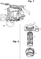
Fig. 1 is an illustration of an Integrated Drive Generator (IDG) coupled to a gas turbine engine and having an oil filter housing that includes the cover of the subject invention; -
Fig. 2 is a perspective view of the cover of the subject invention and the elongated oil filter cartridge removed from the filter housing of the IDG; -
Fig. 3 is a side elevational view of the perspective view of the cover shown inFigs. 1 and 2 ; -
Fig. 4 is a top plan view of the cover; -
Fig. 5 is a cross-sectional view of the cover taken along line 5-5 ofFig. 4 ; -
Fig. 6 is an enlarged localized view of a medial flange portion of the cover taken fromFig. 3 ; and -
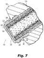
Fig. 7 is an enlarged localized cross-sectional view taken along line 7-7 ofFig. 1 illustrating the elongated oil filter within the housing enclosed by the cover of the subject invention, and showing the path of fluid flow through the oil filter. - Referring now to the drawings wherein like reference numerals identify similar structural features, there is illustrated in
Fig. 1 an Integrated Drive Generator (IDG) 10 coupled to agas turbine engine 12 that employs the new anduseful cover 14 of the subject invention. More particularly, as shown inFig. 2 , thecover 14 is designed to accommodate an elongated radially pleatedoil filter cartridge 16 that has a greater axial length than thefilter housing 18 within which it is accommodated, while remaining within the spatial constraints that permit ready access to and removal of thecover 14 andoil filter cartridge 16 from thehousing 18 of the IDG 10 for routine maintenance purposes. - Referring to
Figs. 3 through 6 , thecover 14 includes anelongated body 20 defining a central longitudinal axis (LAxis) and having anupper end portion 22, alower end portion 24 and amedial abutment flange 26 that surrounds the periphery of thebody 20. Thebody 20 ofcover 14 is preferably formed from 2024 aluminum alloy or a similar material. - The central longitudinal axis LAxis of the
body 20 delineates an axial length (LBody) of thebody 20. More particularly, as shown inFig. 5 , the axial length LBody of thebody 20 ofcover 14 is about 1.69 inches to about 1.72 inches. As best seen inFig. 4 , theupper end portion 22 of thebody 20 ofcover 14 has ahexagonal engagement surface 28 formed thereon for installing thecover 14 on thehousing 18 and for removing thecover 14 from thehousing 18 using a hand tool. - The
lower end portion 24 of thebody 20 ofcover 14 has a helical thread formation with a standard pitch for threadably engaging thehousing 18, as best seen inFig. 3 . Themedial abutment flange 26 of thebody 20 ofcover 14 is best seen inFig. 6 . It is adapted and configured to abut against the outer edge surface of thefilter housing 18 of the IDG 10 when thecover 14 is threadably engaged to thehousing 18, as best seen inFig. 7 - Referring to
Fig. 5 , thebody 20 of thecover 14 hasaxial bore 30 that extends through thebody 20 from thelower end portion 24 to aninterior end wall 32 in theupper end portion 22 for accommodating an axial end portion of theoil filter cartridge 16 located within thehousing 14. Theaxial bore 30 ofbody 20 has an axial length (LBore) of and an inner diameter DBore. The axial length LBore of thebore 30 is about 1.57 inches to about 1.58 inches and the inner diameter DBore of thebore 30 is about 1.81 inches. - In accordance with a preferred embodiment of the subject invention, the axial length LBore of the
bore 30 ofbody 20 is greater than 85% of the axial length LBody of thebody 20. More preferably, the axial length LBore of thebore 30 ofbody 20 is about 90% to about 94% of the axial length LBody of thebody 20. In sum, in an exemplary embodiment of thecover 14, the axial length LBore of thebore 30 ofbody 20 is about 1.56 inches to about 1.59 inches, and the axial length LBody of thebody 20 is about 1.69 inches to about 1.72 inches. - Referring now to
Fig. 7 , when theoil filter 16 is installed in thehousing 18 of the IDG 10, the end portion of theoil filter 16 advantageously fits within theaxial bore 30 of thebody 20 of thecover 14. Moreover, when the end portion of theoil filter 16 is within theaxial bore 30 of thebody 20 ofcover 14, it extends beyond thehousing 18, within thecover 14. This enables theoil filter 16 to have a greater axial length than thefilter housing 18 within which it is accommodated. As a result, the dirt holding capacity and operational life of theoil filter 16 can be optimized, while thecover 14 remains within the spatial constraints that permit ready access to and removal of thecover 14 andoil filter 16 from thehousing 18 ofIDG 10 for routine maintenance purposes. - While the subject disclosure has been shown and described with reference to preferred embodiments, those skilled in the art will readily appreciate that changes and/or modifications may be made thereto without departing from the scope of the subject disclosure.
Claims (15)
- A cover (14) for an oil filter housing (18), comprising:
an elongated body (20) defining an upper end portion (22) and an lower end portion (24), and having a central axis extending therethrough, which delineates an axial length of the body, wherein an axial bore (30) extends through the body of the cover from the lower end portion thereof to an interior end wall in the upper end portion thereof for accommodating an axial end portion of an oil filter located within the housing, the axial bore of the body having an axial length that is greater than 85% of the axial length of the body. - A cover as recited in Claim 1, wherein the axial length of the bore is about 90% to about 94% of the axial length of the body
- A cover as recited in Claim 1 or 2, wherein the axial length of the bore is about 1.56 inches to about 1.59 inches
- A cover as recited in any preceding Claim, wherein the axial length of the body is about 1.69 inches to about 1.72 inches.
- A cover as recited in any preceding Claim, wherein the axial bore has a diameter of about 1.81 inches.
- A cover as recited in any preceding Claim, wherein the body is formed from 2024 aluminum alloy.
- A cover as recited in any preceding Claim, wherein the upper end portion of the body has a hexagonal engagement surface formed thereon.
- A cover (14) for an oil filter housing (18), comprising:
an elongated body (20) defining an upper end portion and an lower end portion, and having a central axis extending therethrough, which delineates an axial length of the body, wherein an axial bore extends through the body of the cover from the lower end portion thereof to an interior end wall in the upper end portion thereof for accommodating an axial portion of an oil filter located within the housing, the axial bore of the body having an axial length that is about 90% to about 94% of the axial length of the body. - A cover as recited in Claim 8, wherein the axial length of the bore is about 1.56 inches to about 1.59 inches
- A cover as recited in Claim 8 or 9, wherein the axial length of the body is about 1.69 inches to about 1.72 inches.
- A cover as recited in any of claims 8 to 10, wherein the axial bore has a diameter of about 1.81 inches.
- A cover as recited in any of claims 8 to 11, wherein the body is formed from 2024 aluminum alloy.
- A cover as recited in any of claims 8 to 12, wherein the upper end portion of the body has a hexagonal engagement surface formed thereon.
- A cover for an oil filter housing, comprising:
an elongated body formed from an aluminum alloy and defining an upper end portion and an lower end portion, and having a central axis extending therethrough, wherein an axial bore extends through the body of the cover from the lower end portion thereof to an interior end wall in the upper end portion thereof for accommodating an axial portion of an oil filter located within the housing, the body having an axial length of about 1.69 inches to about 1.72 inches, and the axial bore having an axial length of about 1.56 inches to about 1.59 inches and a diameter of about 1.81 inches. - A cover as recited in Claim 14, wherein the body is formed from 2024 aluminum alloy.
Applications Claiming Priority (1)
| Application Number | Priority Date | Filing Date | Title |
|---|---|---|---|
| US16/298,628 US20200291836A1 (en) | 2019-03-11 | 2019-03-11 | Cover for oil filter housing of an integrated drive generator |
Publications (1)
| Publication Number | Publication Date |
|---|---|
| EP3708233A1 true EP3708233A1 (en) | 2020-09-16 |
Family
ID=68916247
Family Applications (1)
| Application Number | Title | Priority Date | Filing Date |
|---|---|---|---|
| EP19215793.1A Withdrawn EP3708233A1 (en) | 2019-03-11 | 2019-12-12 | Cover for oil filter housing of an integrated drive generator |
Country Status (3)
| Country | Link |
|---|---|
| US (1) | US20200291836A1 (en) |
| EP (1) | EP3708233A1 (en) |
| CN (1) | CN111678024A (en) |
Citations (5)
| Publication number | Priority date | Publication date | Assignee | Title |
|---|---|---|---|---|
| DE19637008A1 (en) * | 1996-09-12 | 1998-03-19 | Knecht Filterwerke Gmbh | Engine oil filter for motor vehicle with housing and lid joined by screw thread |
| US20040188346A1 (en) * | 2003-03-28 | 2004-09-30 | Cline L. Steven | Filter apparatus and associated method |
| JP2005337172A (en) * | 2004-05-28 | 2005-12-08 | Toyota Motor Corp | Element exchange type filter |
| DE102011005943A1 (en) * | 2011-03-23 | 2012-09-27 | Mahle International Gmbh | Filter device for filtering liquid or gaseous fluids, has pressure detecting unit arranged inside housing and evaluating device which is arranged outside housing and cooperated contactlessly with pressure detecting unit through housing |
| JP2014213252A (en) * | 2013-04-24 | 2014-11-17 | 株式会社パイオラックス | Cover member |
Family Cites Families (2)
| Publication number | Priority date | Publication date | Assignee | Title |
|---|---|---|---|---|
| US5374354A (en) * | 1992-09-24 | 1994-12-20 | Sundstrand Corporation | Method of increasing service life of oil and a filter in an integrated drive generator or constant speed drive and improved oil filter for use therein |
| US6770196B2 (en) * | 2002-03-20 | 2004-08-03 | Arvin Technologies, Inc. | Filter cap with releasable filter element |
-
2019
- 2019-03-11 US US16/298,628 patent/US20200291836A1/en not_active Abandoned
- 2019-12-12 EP EP19215793.1A patent/EP3708233A1/en not_active Withdrawn
- 2019-12-13 CN CN201911285897.6A patent/CN111678024A/en active Pending
Patent Citations (5)
| Publication number | Priority date | Publication date | Assignee | Title |
|---|---|---|---|---|
| DE19637008A1 (en) * | 1996-09-12 | 1998-03-19 | Knecht Filterwerke Gmbh | Engine oil filter for motor vehicle with housing and lid joined by screw thread |
| US20040188346A1 (en) * | 2003-03-28 | 2004-09-30 | Cline L. Steven | Filter apparatus and associated method |
| JP2005337172A (en) * | 2004-05-28 | 2005-12-08 | Toyota Motor Corp | Element exchange type filter |
| DE102011005943A1 (en) * | 2011-03-23 | 2012-09-27 | Mahle International Gmbh | Filter device for filtering liquid or gaseous fluids, has pressure detecting unit arranged inside housing and evaluating device which is arranged outside housing and cooperated contactlessly with pressure detecting unit through housing |
| JP2014213252A (en) * | 2013-04-24 | 2014-11-17 | 株式会社パイオラックス | Cover member |
Also Published As
| Publication number | Publication date |
|---|---|
| CN111678024A (en) | 2020-09-18 |
| US20200291836A1 (en) | 2020-09-17 |
Similar Documents
| Publication | Publication Date | Title |
|---|---|---|
| EP0137636A2 (en) | Filter assembly | |
| EP1017468A1 (en) | Arrangement and method for sealing fluid filters | |
| US10232294B2 (en) | Separation element and pressure accumulator system | |
| US20120261325A1 (en) | Filter Assembly Locking Mechanism and Method of Using Same | |
| KR20070077127A (en) | Coaxial All Flow and Bypass Oil Filter Apparatus and Method | |
| EP2612043B1 (en) | Locking nut assembly | |
| CN106132504A (en) | The natural gas filter that buckle puts in place | |
| EP2859950A1 (en) | Sealing ring for gyratory crusher | |
| EP3708233A1 (en) | Cover for oil filter housing of an integrated drive generator | |
| EP2631481A1 (en) | Pump device | |
| US9255501B2 (en) | Threadless magnetic oil drain plug | |
| EP2194299A1 (en) | Sealing device | |
| CN102211063B (en) | With the whizzer of snap fit separation cone | |
| US10215335B2 (en) | Self-retaining oil nozzle | |
| EP2787248A2 (en) | Ballscrew assembly having a low friction sleeve | |
| EP3708234A1 (en) | Oil filter assembly for an integrated drive generator | |
| US20150308306A1 (en) | Device to transfer lubricant in a lubricating assembly and implementation thereof | |
| CA3160550A1 (en) | Downhole sand separating apparatus with erosion resistant centrifugal separator | |
| US10195548B2 (en) | Filter cartridge with integral lock ring | |
| CN110307161B (en) | Improved minimum pressure valve and method for servicing such a valve | |
| US8815087B2 (en) | Fluid filter | |
| EP4640294A1 (en) | Filter housing for spin-on or bowl cartridge assemblies | |
| US20060242934A1 (en) | Air filter assembly | |
| CN218266831U (en) | Wear-resistant middle sleeve of chain wheel assembly | |
| CN103982342A (en) | Filter system |
Legal Events
| Date | Code | Title | Description |
|---|---|---|---|
| PUAI | Public reference made under article 153(3) epc to a published international application that has entered the european phase |
Free format text: ORIGINAL CODE: 0009012 |
|
| STAA | Information on the status of an ep patent application or granted ep patent |
Free format text: STATUS: THE APPLICATION HAS BEEN PUBLISHED |
|
| AK | Designated contracting states |
Kind code of ref document: A1 Designated state(s): AL AT BE BG CH CY CZ DE DK EE ES FI FR GB GR HR HU IE IS IT LI LT LU LV MC MK MT NL NO PL PT RO RS SE SI SK SM TR |
|
| AX | Request for extension of the european patent |
Extension state: BA ME |
|
| STAA | Information on the status of an ep patent application or granted ep patent |
Free format text: STATUS: THE APPLICATION IS DEEMED TO BE WITHDRAWN |
|
| 18D | Application deemed to be withdrawn |
Effective date: 20210317 |