EP3708217A1 - Flush device and irrigation line - Google Patents
Flush device and irrigation line Download PDFInfo
- Publication number
- EP3708217A1 EP3708217A1 EP18875996.3A EP18875996A EP3708217A1 EP 3708217 A1 EP3708217 A1 EP 3708217A1 EP 18875996 A EP18875996 A EP 18875996A EP 3708217 A1 EP3708217 A1 EP 3708217A1
- Authority
- EP
- European Patent Office
- Prior art keywords
- housing
- flow path
- control device
- elastic member
- flow control
- Prior art date
- Legal status (The legal status is an assumption and is not a legal conclusion. Google has not performed a legal analysis and makes no representation as to the accuracy of the status listed.)
- Granted
Links
- LWDUGATUDNIVEU-UHFFFAOYSA-N C=C1CC=CC1 Chemical compound C=C1CC=CC1 LWDUGATUDNIVEU-UHFFFAOYSA-N 0.000 description 1
Images





Classifications
-
- A—HUMAN NECESSITIES
- A61—MEDICAL OR VETERINARY SCIENCE; HYGIENE
- A61M—DEVICES FOR INTRODUCING MEDIA INTO, OR ONTO, THE BODY; DEVICES FOR TRANSDUCING BODY MEDIA OR FOR TAKING MEDIA FROM THE BODY; DEVICES FOR PRODUCING OR ENDING SLEEP OR STUPOR
- A61M39/00—Tubes, tube connectors, tube couplings, valves, access sites or the like, specially adapted for medical use
- A61M39/22—Valves or arrangement of valves
- A61M39/225—Flush valves, i.e. bypass valves for flushing line
-
- A—HUMAN NECESSITIES
- A61—MEDICAL OR VETERINARY SCIENCE; HYGIENE
- A61B—DIAGNOSIS; SURGERY; IDENTIFICATION
- A61B5/00—Measuring for diagnostic purposes; Identification of persons
- A61B5/68—Arrangements of detecting, measuring or recording means, e.g. sensors, in relation to patient
- A61B5/6846—Arrangements of detecting, measuring or recording means, e.g. sensors, in relation to patient specially adapted to be brought in contact with an internal body part, i.e. invasive
- A61B5/6847—Arrangements of detecting, measuring or recording means, e.g. sensors, in relation to patient specially adapted to be brought in contact with an internal body part, i.e. invasive mounted on an invasive device
- A61B5/6852—Catheters
-
- A—HUMAN NECESSITIES
- A61—MEDICAL OR VETERINARY SCIENCE; HYGIENE
- A61M—DEVICES FOR INTRODUCING MEDIA INTO, OR ONTO, THE BODY; DEVICES FOR TRANSDUCING BODY MEDIA OR FOR TAKING MEDIA FROM THE BODY; DEVICES FOR PRODUCING OR ENDING SLEEP OR STUPOR
- A61M3/00—Medical syringes, e.g. enemata; Irrigators
- A61M3/02—Enemata; Irrigators
- A61M3/0279—Cannula; Nozzles; Tips; their connection means
-
- A—HUMAN NECESSITIES
- A61—MEDICAL OR VETERINARY SCIENCE; HYGIENE
- A61M—DEVICES FOR INTRODUCING MEDIA INTO, OR ONTO, THE BODY; DEVICES FOR TRANSDUCING BODY MEDIA OR FOR TAKING MEDIA FROM THE BODY; DEVICES FOR PRODUCING OR ENDING SLEEP OR STUPOR
- A61M39/00—Tubes, tube connectors, tube couplings, valves, access sites or the like, specially adapted for medical use
- A61M39/10—Tube connectors or tube couplings
-
- A—HUMAN NECESSITIES
- A61—MEDICAL OR VETERINARY SCIENCE; HYGIENE
- A61M—DEVICES FOR INTRODUCING MEDIA INTO, OR ONTO, THE BODY; DEVICES FOR TRANSDUCING BODY MEDIA OR FOR TAKING MEDIA FROM THE BODY; DEVICES FOR PRODUCING OR ENDING SLEEP OR STUPOR
- A61M39/00—Tubes, tube connectors, tube couplings, valves, access sites or the like, specially adapted for medical use
- A61M39/22—Valves or arrangement of valves
- A61M39/223—Multiway valves
-
- A—HUMAN NECESSITIES
- A61—MEDICAL OR VETERINARY SCIENCE; HYGIENE
- A61M—DEVICES FOR INTRODUCING MEDIA INTO, OR ONTO, THE BODY; DEVICES FOR TRANSDUCING BODY MEDIA OR FOR TAKING MEDIA FROM THE BODY; DEVICES FOR PRODUCING OR ENDING SLEEP OR STUPOR
- A61M5/00—Devices for bringing media into the body in a subcutaneous, intra-vascular or intramuscular way; Accessories therefor, e.g. filling or cleaning devices, arm rests
- A61M5/14—Infusion devices, e.g. infusing by gravity; Blood infusion; Accessories therefor
-
- A—HUMAN NECESSITIES
- A61—MEDICAL OR VETERINARY SCIENCE; HYGIENE
- A61M—DEVICES FOR INTRODUCING MEDIA INTO, OR ONTO, THE BODY; DEVICES FOR TRANSDUCING BODY MEDIA OR FOR TAKING MEDIA FROM THE BODY; DEVICES FOR PRODUCING OR ENDING SLEEP OR STUPOR
- A61M5/00—Devices for bringing media into the body in a subcutaneous, intra-vascular or intramuscular way; Accessories therefor, e.g. filling or cleaning devices, arm rests
- A61M5/14—Infusion devices, e.g. infusing by gravity; Blood infusion; Accessories therefor
- A61M5/168—Means for controlling media flow to the body or for metering media to the body, e.g. drip meters, counters
- A61M5/16804—Active flow controllers
-
- A—HUMAN NECESSITIES
- A61—MEDICAL OR VETERINARY SCIENCE; HYGIENE
- A61M—DEVICES FOR INTRODUCING MEDIA INTO, OR ONTO, THE BODY; DEVICES FOR TRANSDUCING BODY MEDIA OR FOR TAKING MEDIA FROM THE BODY; DEVICES FOR PRODUCING OR ENDING SLEEP OR STUPOR
- A61M5/00—Devices for bringing media into the body in a subcutaneous, intra-vascular or intramuscular way; Accessories therefor, e.g. filling or cleaning devices, arm rests
- A61M5/14—Infusion devices, e.g. infusing by gravity; Blood infusion; Accessories therefor
- A61M5/168—Means for controlling media flow to the body or for metering media to the body, e.g. drip meters, counters
- A61M5/16877—Passive flow controllers; Devices for setting a flow rate
- A61M5/16881—Regulating valves
-
- F—MECHANICAL ENGINEERING; LIGHTING; HEATING; WEAPONS; BLASTING
- F16—ENGINEERING ELEMENTS AND UNITS; GENERAL MEASURES FOR PRODUCING AND MAINTAINING EFFECTIVE FUNCTIONING OF MACHINES OR INSTALLATIONS; THERMAL INSULATION IN GENERAL
- F16L—PIPES; JOINTS OR FITTINGS FOR PIPES; SUPPORTS FOR PIPES, CABLES OR PROTECTIVE TUBING; MEANS FOR THERMAL INSULATION IN GENERAL
- F16L33/00—Arrangements for connecting hoses to rigid members; Rigid hose-connectors, i.e. single members engaging both hoses
- F16L33/02—Hose-clips
- F16L33/03—Self-locking elastic clips
-
- A—HUMAN NECESSITIES
- A61—MEDICAL OR VETERINARY SCIENCE; HYGIENE
- A61B—DIAGNOSIS; SURGERY; IDENTIFICATION
- A61B5/00—Measuring for diagnostic purposes; Identification of persons
- A61B5/02—Detecting, measuring or recording for evaluating the cardiovascular system, e.g. pulse, heart rate, blood pressure or blood flow
- A61B5/021—Measuring pressure in heart or blood vessels
- A61B5/0215—Measuring pressure in heart or blood vessels by means inserted into the body
-
- A—HUMAN NECESSITIES
- A61—MEDICAL OR VETERINARY SCIENCE; HYGIENE
- A61B—DIAGNOSIS; SURGERY; IDENTIFICATION
- A61B5/00—Measuring for diagnostic purposes; Identification of persons
- A61B5/03—Measuring fluid pressure within the body other than blood pressure, e.g. cerebral pressure ; Measuring pressure in body tissues or organs
- A61B5/036—Measuring fluid pressure within the body other than blood pressure, e.g. cerebral pressure ; Measuring pressure in body tissues or organs by means introduced into body tracts
-
- A—HUMAN NECESSITIES
- A61—MEDICAL OR VETERINARY SCIENCE; HYGIENE
- A61M—DEVICES FOR INTRODUCING MEDIA INTO, OR ONTO, THE BODY; DEVICES FOR TRANSDUCING BODY MEDIA OR FOR TAKING MEDIA FROM THE BODY; DEVICES FOR PRODUCING OR ENDING SLEEP OR STUPOR
- A61M5/00—Devices for bringing media into the body in a subcutaneous, intra-vascular or intramuscular way; Accessories therefor, e.g. filling or cleaning devices, arm rests
- A61M5/14—Infusion devices, e.g. infusing by gravity; Blood infusion; Accessories therefor
- A61M2005/1401—Functional features
- A61M2005/1403—Flushing or purging
-
- A—HUMAN NECESSITIES
- A61—MEDICAL OR VETERINARY SCIENCE; HYGIENE
- A61M—DEVICES FOR INTRODUCING MEDIA INTO, OR ONTO, THE BODY; DEVICES FOR TRANSDUCING BODY MEDIA OR FOR TAKING MEDIA FROM THE BODY; DEVICES FOR PRODUCING OR ENDING SLEEP OR STUPOR
- A61M2205/00—General characteristics of the apparatus
- A61M2205/02—General characteristics of the apparatus characterised by a particular materials
- A61M2205/0216—Materials providing elastic properties, e.g. for facilitating deformation and avoid breaking
-
- A—HUMAN NECESSITIES
- A61—MEDICAL OR VETERINARY SCIENCE; HYGIENE
- A61M—DEVICES FOR INTRODUCING MEDIA INTO, OR ONTO, THE BODY; DEVICES FOR TRANSDUCING BODY MEDIA OR FOR TAKING MEDIA FROM THE BODY; DEVICES FOR PRODUCING OR ENDING SLEEP OR STUPOR
- A61M2230/00—Measuring parameters of the user
- A61M2230/30—Blood pressure
-
- A—HUMAN NECESSITIES
- A61—MEDICAL OR VETERINARY SCIENCE; HYGIENE
- A61M—DEVICES FOR INTRODUCING MEDIA INTO, OR ONTO, THE BODY; DEVICES FOR TRANSDUCING BODY MEDIA OR FOR TAKING MEDIA FROM THE BODY; DEVICES FOR PRODUCING OR ENDING SLEEP OR STUPOR
- A61M39/00—Tubes, tube connectors, tube couplings, valves, access sites or the like, specially adapted for medical use
- A61M39/22—Valves or arrangement of valves
- A61M39/229—Single-way cut-off valves
Definitions
- the present invention relates to a flush device and an irrigation line including the flush device.
- irrigation lines also referred to as pressure monitoring tube sets
- blood pressure or fluid pressure is measured by converting the blood pressure or fluid pressure transmitted through a catheter and a tube into an electrical signal using a pressure transducer.
- the tube Before the catheter is inserted into the body of a patient, the tube is filled with a physiological saline solution. If a thrombus is formed in the tube or in a portion of the catheter, the thrombus may enter the body of the patient through the catheter.
- the irrigation line is provided with a flush device which is configured to contiguously discharge a small amount of physiological saline solution to prevent any thrombi from being formed in the tube or the like.
- Patent Document 1 discloses a flush device including a first housing provided with a first flow path located on a side of a supply source of physiological saline solution, a second housing provided with a second flow path located on a side of the body of a patient, and a flow control device provided between the first flow path and the second flow path.
- the flow control device is provided with an orifice with a small diameter.
- the physiological saline solution in trace amounts coming from the first flow path is contiguously discharged toward the second flow path through the orifice.
- the flow control device is fixed to the second housing by ultrasonic welding.
- the flush device is required to discharge a physiological saline solution at a flow rate close to a defined amount.
- the flush device of Patent Document 1 employs a structure in which the flow control device is fixed to the second housing by ultrasonic bonding, the structure having room for improvement in terms of a mechanism for positioning the flow control device.
- the present invention is made to solve the above-described problem, and an object thereof is to provide a flush device capable of discharging a chemical liquid at a flow rate close to a defined amount.
- the present invention is directed to a flush device including:
- the fitting projections of the flow control device are fitted to the fitting receiving portions of the first housing, so that the flow control device can be disposed with the through hole extending along the central axis of the first housing.
- a flush device can be realized for discharging a chemical liquid at a flow rate closer to a defined amount through the flow control device.
- Fig. 1 illustrates an irrigation line 10 provided with a flush device 1 according to a first embodiment of the present invention.
- the irrigation line 10 includes a bottle needle 11, a pressure transducer 12, a three-way stopcock 13, a connector 14, and the like, along with the flush device 1.
- the bottle needle 11 and the flush device 1 are connected to each other with a tube 15, and the three-way stopcock 13 and the connector 14 are connected to each other with a tube 16.
- the flush device 1, the pressure transducer 12, and the three-way stopcock 13 may be directly connected to each other.
- the connector 14 is connected to a chemical liquid source (not shown).
- the irrigation line 10 provided with the pressure transducer 12 may be particularly referred to as a pressure monitoring tube set. However, in the present specification, the irrigation line 10 may not include the pressure transducer 12.
- the irrigation line 10 may be used for invasive blood pressure measurement and cerebrospinal fluid pressure measurement during surgery.
- the pressure transducer 12 is connected to a controller 17.
- the pressure transducer 12 converts blood pressure or fluid pressure transmitted through the bottle needle 11 and the tube 15 into an electric signal and transmits it to the controller 17.
- the controller 17 includes a CPU (central processing unit), a memory, a monitor, and the like, and is configured to digitally process the transmitted electric signal and display the blood pressure or the fluid pressure on the monitor. While in the present embodiment, the pressure transducer 12 is attached detachably from the irrigation line 10, it may be integrated with the irrigation line 10.
- the flush device 1 includes a casing 2, a flow control device 3, an elastic member 4, and a pair of wings 5, 5.
- the flush device 1 is configured to contiguously discharge a small amount of chemical liquid through the flow control device 3.
- the flow control device 3 and the elastic member 4 are accommodated in the casing 2.
- the pair of wings 5, 5 is attached to the casing 2.
- Figs. 2 to 7 illustrate the flush device 1 with the pair of wings 5, 5 closed.
- the casing 2, the flow control device 3, and the pair of wings 5, 5 may be made of a resin material, such as ABS resin, polycarbonate resin, etc.
- the elastic member 4 may be made of an elastomeric material, such as silicone.
- a chemical liquid source side of a position where the flush device 1 is disposed in the irrigation line 10 is referred to as an upstream side
- a bottle needle 11 side of a position where the flush device 1 is disposed in the irrigation line 10 is referred to as a downstream side.
- two directions perpendicular to the direction extending from the upstream side to the downstream side can be defined, one direction extending through the pair of wings 5, 5, being referred to as a horizontal direction, and another direction perpendicular to the longitudinal direction and the horizontal direction, being referred to as a vertical direction.
- the casing 2 includes a first housing 6 and a second housing 7 that are coupled to each other.
- the first housing 6 is disposed on the upstream side
- the second housing 7 is disposed on the downstream side.
- the first housing 6 includes an elongated body 62 having a first flow path 61 inside.
- the first flow path 61 has a central axis 101, and the body 62 of the first housing 6 extends along the central axis 101.
- the direction in which the central axis 101 extends is referred to as an axial direction of the first housing 6, and any direction orthogonal to the axial direction is referred to as a radial direction of the first housing 6.
- the first flow path 61 extends in a tapered shape from the upstream side to the downstream side.
- the first flow path 61 is provided at one end (upstream end) with an inlet 61a, and at the other end (downstream end) with an outlet 61b.
- the inlet 61a of the first flow path 61 serves as an inlet of the flush device 1.
- the inlet 61a of the first flow path 61 is circular.
- the outlet 61b of the first flow path 61 is formed crisscross (in a cross shape).
- the body 62 has a downstream end portion 63 defining the outlet 61b of the first flow path 61, to which the flow control device 3 is attached.
- the outlet 61b formed crisscross includes a hole extending in the vertical direction, the hole communicating with upper and lower slot grooves 64, 64 extending in the axial direction (to the upstream side) from a downstream end surface of the body 62.
- the slot grooves 64, 64 extend radially through a peripheral wall of the body 62.
- the downstream end portion 63 of the first housing 6 includes a plurality of holes 65 provided on an inner periphery defining the first flow path 61 of the body 62.
- the hole 65 function as a fitting receiving portion for fitting and fixing the flow control device 3 to the first housing 6.
- the hole 65 have a rectangular shape when viewed laterally.
- the plurality of holes 65 is preferably provided at equal intervals in a circumferential direction. In the present embodiment, two holes 65 are provided on the left and right sides at 180 degree intervals.
- the hole 65 is a through hole passing through the peripheral wall of the body 62 in the radial direction.
- the hole 65 may be a non-through (blind) hole that does not pass through the peripheral wall of the body 62 in the radial direction.
- a part of the peripheral wall of the body 62, located on the downstream side of the hole 65 is referred to as a spacer receiving portion 66.
- the body 62 of the first housing 6 is provided at its upstream end with a male connector 67.
- the male connector 67 can be attached to a female connector (not shown) provided in the pressure transducer 12 illustrated in Fig. 1 .
- the second housing 7 includes an elongated body 72 having a second flow path 71 inside.
- the second flow path 71 has a central axis 102, and the body 72 of the second housing 7 extends along the central axis 102.
- the direction in which the central axis 102 extends is referred to as an axial direction of the second housing 7, and any direction in a plane orthogonal to the axial direction is referred to as a radial direction of the second housing 7.
- the central axis 102 of the second flow path 71 extends along the central axis 101 of the first flow path 61.
- the central axis 102 of the second flow path 71 and the central axis 101 of the first flow path 61 may not extend completely in one straight line. Both the central axes 101, 102 may be disposed displaced (non-parallel) from each other, as long as effects of the present invention can be achieved.
- the second flow path 71 extends in a tapered shape from the upstream side to the downstream side.
- the second flow path 71 is provided at one end (upstream end) with an inlet 71a, and at the other end (downstream end) with an outlet 71b.
- the inlet 71a and the outlet 71b of the second flow path 71 are circular.
- the outlet 71b of the second flow path 71 serves as an outlet of the flush device 1.
- the body 72 has an upstream end portion 73 that defines the inlet 71a of the second flow path 71 and that is located close to the flow control device 3.
- a female connector 18 is attached to a downstream end portion of the body 72 of the second housing 7.
- the female connector 18 is attached to a male connector (not illustrated) provided in the tube 15 illustrated in Fig. 1 .
- the first housing 6 and the second housing 7 are coupled to each other by means of a coupling mechanism.
- the coupling mechanism includes a first coupler 8 provided at the downstream end of the first housing 6 and a second coupler 9 provided at the upstream end of the second housing 7.
- the first coupler 8 includes a cup portion 81 that opens on the downstream side in the axial direction.
- the cup portion 81 is provided on its downstream end with an L-shaped plate 82 as viewed from the side.
- the plate 82 includes a vertical plate 82a extending in the vertical direction and a horizontal plate 82b extending downstream in the axial direction.
- the horizontal plate 82b has a T-shaped end face 82c as viewed from the downstream side in the axial direction.
- the horizontal plate 82b is provided on its lower side with a tongue portion 83 extending axially downstream from the vertical plate 82a.
- the tongue portion 83 is provided at its downstream end with a fitting claw 83a protruding upward.
- the tongue portion 83 is provided in its upper surface with a recessed portion defined by the horizontal plate 82b and the fitting claw 83a. This recessed portion is referred to as a bridge receiving portion 84.
- the cup portion 81 is provided in its lower downstream end with a panel 85.
- the panel 85 includes a horizontal plate 86 extending downstream in the axial direction.
- the horizontal plate 86 is provided on its upper side with a tongue portion 87 extending downstream in the axial direction from the panel 85.
- the tongue portion 87 is provided at its downstream end with a fitting claw 87a protruding downward.
- the panel 85 includes a pair of circular shaft holes 88, 88 located laterally on both side of the horizontal plate 86 and the tongue portion 87.
- the second coupler 9 includes a cup portion 91 that opens on the upstream side in the axial direction.
- the cup portion 91 is provided in its upper upstream end portion with a pair of beams 92, 92 laterally arranged that are fixed to the cup portion 91 and that extend upstream in the axial direction.
- the pair of beams 92, 92 are separated from each other by a distance equivalent to a horizontal dimension (or width) of the tongue portion 83 of the first coupler 8 in such a manner to interpose and engage with the tongue portion 83 when the first housing 6 and the second housing 7 are coupled to each other.
- the second coupler 9 includes a bridge 93 connecting the beams 92, 92.
- the fitting claw 83a is fitted (snap-fitted) on the downstream side of the bridge 93.
- the bridge 93 has a longitudinal dimension equivalent to a longitudinal dimension (or length) of the bridge receiving portion 84 in such a manner to fit into the bridge receiving portion 84 of the first coupler 8.
- the bridge 93 functions as a claw receiving portion that receives the fitting claw 83a.
- the arms 94, 94 are fitted into respective corners of a T-shape of the horizontal plate 82b when the first housing 6 is coupled to the second housing 7.
- the horizontal plate 82b receives the arms 94, 94 and functions as an arm receiving portion that restricts relative rotation of the first housing 6 with respect to the second housing 7.
- the arms 94, 94 have such a longitudinal dimension as to butt a downstream surface of the vertical plate 82a of the plate 82.
- the cup portion 91 is provided in its lower downstream end with a panel 95.
- the panel 95 includes a pair of beams 96, 96 extending upstream in the axial direction.
- the beams 96, 96 are separated from each other by a distance equivalent to a horizontal dimension (or width) of the tongue portion 87 of the first coupler 8 in such a manner to interpose and engage with the tongue portion 87 when the first housing 6 and the second housing 7 are coupled to each other.
- the second coupler 9 includes an inclined wall 97 provided between the beams 96, 96.
- the inclined wall 97 extends obliquely upward with respect to the longitudinal direction as going from the upstream side toward the downstream side.
- the fitting claw 87a is fitted (snap-fitted) on a downstream side of the inclined wall 97.
- the inclined wall 97 functions as a claw receiving portion that receives the fitting claw 83a.
- the beams 96, 96 have upstream ends in which only upper portions of the beams 96, 96 protrude upstream, constituting a pair of arms 98, 98 laterally arranged.
- the arms 98, 98 are fitted into respective corners formed by the horizontal plate 86 and the tongue portion 87 when the first housing 6 is coupled to the second housing 7.
- the horizontal plate 86 and the tongue portion 87 work together to receive the arms 98, 98 and function as an arm receiving portion that restricts relative rotation of the first housing 6 with respect to the second housing 7.
- the arms 98, 98 have such a longitudinal dimension as to butt a downstream surface of the panel 85.
- the panel 95 includes a pair of circular shaft holes 99, 99 located laterally on both side of the beams 96, 96.
- the flow control device 3 includes a base 31 and a protrusion 32 extending from the base 31.
- the base 31 has a diameter larger than a diameter of the protrusion 32.
- the base 31 and the protrusion 32 each have a columnar shape.
- the base 31 is located between the first flow path 61 and the second flow path 71.
- the protrusion 32 has a base end 32a on a side of the base 31 and a leading end 32b on the side opposite to the base end 32a. Most of the protrusion 32 including the leading end 32b is located inside the first flow path 61.
- the base 31 includes a recessed portion 34.
- the protrusion 32 is disposed with a predetermined interval 104 away from the inner periphery of the body 62 of the first housing 6 (See Fig. 12 ).
- the flow control device 3 is attached to the downstream end portion 63 of the first housing 6.
- the base 31 has a dimension (diameter) to completely cover a downstream end face of the first housing 6 as the flow control device 3 is attached to the downstream end portion 63 of the first housing 6.
- the base 31 preferably has a diameter substantially equivalent to a diameter of the downstream end portion 63 of the first housing 6.
- the flow control device 3 is provided with a through hole 33 extending through the base 31 and the protrusion 32.
- the through hole 33 has such an inner diameter as to function as a capillary.
- the flush device 1 discharges a chemical liquid at a flow rate that decreases with decrease in diameter of the through hole 33 and with increase in length thereof.
- the through hole 33 has a central axis 103, and the protrusion 32 extends along the central axis 103.
- a direction in which the central axis 103 extends is referred to as an axial direction of the flow control device 3, and any direction in a plane orthogonal to the axial direction is referred to as a radial direction of the flow control device 3.
- the central axis 103 of the through hole 33 extends along the central axis 101 of the first flow path 61 (and the central axis 102 of the second flow path 71).
- the central axis 103 of the through hole 33 may not extend completely in one straight line with the central axis 101 of the first flow path 61 (and the central axis 102 of the second flow path 71).
- the central axes 101, 102, 103 may be disposed displaced (non-parallel) from each other, as long as effects of the present invention can be achieved.
- the through hole 33 connects the first flow path 61 and the second flow path 71 in fluid communication in the flush device 1.
- the through hole 33 has an inlet 33a and an outlet 33b.
- the inlet 33a communicates with the first flow path 61 provided in the first housing 6, and the outlet 33b communicates with the second flow path 71 provided in the second housing 7.
- the protrusion 32 is provided on its outer periphery with a plurality of fitting projections 35 projecting radially outward.
- the fitting projections 35 are fitted (snap-fitted) into the corresponding holes 65 provided in the first housing 6, so that the flow control device 3 is fixed to the first housing 6.
- the plurality of fitting projections 35 are also provided at equal intervals in the circumferential direction.
- the number of the fitting projections 35 may be equal to that of the holes 65.
- the fitting projections 35 each have a shape complementary to the hole 65, and in the present embodiment, each have a shape similar to a rectangular parallelepiped. However, the fitting projections 35 are each provided with an inclined surface 35a to facilitate fitting of the fitting projections 35 into the corresponding holes 65.
- a plurality of spacers 36 are provided on the outer periphery of the protrusion 32 and on the side of the base end 32a of the plurality of fitting projections 35.
- the spacers 36 each have a rectangular parallelepiped shape.
- the spacers 36 each protrude radially outward from the outer periphery of the protrusion 32 toward the inner periphery defining the first flow path 61.
- two spacers 36 are provided on the left and right sides at 180 degree intervals apart from each other, as two holes 65 are provided on the left and right sides at 180 degree intervals apart from each other.
- the plurality of spacers 36 each butt the inner periphery defining the first flow path 61. It is preferable that the plurality of spacers 36 each have such a dimension as to butt and bump the inner periphery.
- a predetermined interval may exist between a radially outer end of each of the plurality of spacers 36 and the inner periphery.
- the elastic member 4 includes a tubular portion 41 and a block portion 42 provided around the tubular portion 41.
- the tubular portion 41 is provided around the base 31 of the flow control device 3.
- the tubular portion 41 includes a hollow portion 41a in which the base 31 and the downstream end portion 63 of the first housing 6 are biased to be accommodated. This can seal off a space between the first flow path 61 and the second flow path 71, and the first flow path 61 is connected to the second flow path 71 in fluid communication only via the through hole 33.
- the elastic member 4 can suitably accommodate them.
- the elastic member 4 is biased to be held between the upper and lower tongue portions 83, 87 of the first coupler 8 on the upstream side, and is biased to be held between the upper and lower arms 94, 98 of the second coupler 9 on the downstream.
- the block portion 42 has a square shape when viewed in the axial direction.
- the block portion 42 includes an upper surface 42a and a lower surface 42b that are respectively in contact with the upper and lower tongue portions 83, 87 of the first coupler 8, and side surfaces 42c, 42d orthogonal to the upper surface 42a and the lower surface 42b.
- the block portion 42 is provided at its axially central portion with a bump 43 throughout the circumference thereof.
- the bump 43 is provided integrally with the block portion 42.
- the bump 43 is viewed from the outside to function as a positioning marker for checking whether the elastic member 4 is disposed at a correct position.
- the side surfaces 42c, 42d of the block portion 42 are partially exposed to the pair of wings 5, 5 without being covered with the casing 2.
- the elastic member 4 is configured to be deformed when receiving a force from the pair of wings 5, 5 to form a gap between the elastic member 4 and the outer periphery of the base 31 of the flow control device 3. This can create a bypass flow path 105 (See Fig. 17 ) for further fluid connection between the first flow path 61 and the second flow path 71.
- each of the wings 5, 5 includes a plate-shaped body 51, a cylindrical shaft portion 52 that is provided at the bottom of the body 51 and that extends parallel to the central axis 101, and a connecting portion 53 for connecting the body 51 and the shaft portion 52.
- the connecting portion 53 extends obliquely with respect to the body 51 when viewed in the axial direction.
- the shaft portion 52 is inserted into the shaft hole 89 of the first coupler 8 and the shaft hole 99 of the second coupler 9.
- the shaft portion 52 has a diameter slightly smaller than a diameter of each of the shaft holes 89 and 99.
- the shaft portion 52 and the shaft hole 89 form a hinge mechanism. In this way the pair of wings 5, 5 can be supported by the first housing 6 and the second housing 7 so as to rotate around each shaft portion 52.
- a hinge mechanism may be formed by providing a protrusion on each of the first coupler 8 and the second coupler 9 and fitting the protrusion to a recessed portion each provided on the shaft members.
- the body 51 is provided on its inner surface with a pressing portion 54.
- the pressing portion 54 is a protrusion that can press each of the side surfaces 42c, 42d of the block portion 42 of the elastic member 4 when the pair of wings 5, 5 is rotated inward around the shaft portions 52, 52 toward the elastic member 4.
- the pressing portion 54 presses an upper portion of each of the side surfaces 42c and 42d of the block portion 42.
- the body 51 is provided on its outer surface with a knob 55 that is a protrusion extending along the axial direction, thereby allowing a user to easily operate the pair of wings 5, 5.
- the fitting projection 35 of the flow control device 3 is fitted (snap-fitted) into the hole 65 of the first housing 6, so that the flow control device 3 is fixed to the first housing 6.
- the plurality of spacers 36 each butt the inner periphery defining the first flow path 61.
- the base 31 of the flow control device 3 and the downstream end portion 63 of the first housing 6 are inserted into the hollow portion 41a of the tubular portion 41 of the elastic member 4.
- the elastic member 4 is held between the upper and lower tongue portions 83, 87 of the first coupler 8 on the upstream side, and is held between the upper and lower arms 94, 98 of the second coupler 9 on the downstream side.
- This allows the flow control device 3 to be more reliably fixed to the first housing 6, so that the flow control device 3 is positioned with higher accuracy in the radial direction and the axial direction.
- the elastic member 4 is disposed at a correct position (in the present embodiment, the position of the base 31 of the flow control device 3) by observing the position of the bump 43 provided on the block portion 42 of the elastic member 4 from the outside.
- the first housing 6 is coupled to the second housing 7. Specifically, the fitting claws 83a are fitted to the downstream side of the bridge 93 (snap fitted) while the shaft portions 52, 52 are inserted into the corresponding shaft holes 88, 88 of the panel 85 and the corresponding shaft holes 99, 99 of the panel 95, and thus the bridge receiving portion 84 of the first coupler 8 is fitted to the bridge 93 of the second coupler 9.
- the first housing 6 is coupled to the second housing 7, and the second housing 7 is positioned with respect to the first housing 6 in the radial direction and the axial direction, thereby the central axis 102 of the second flow path 71 extending along the central axis 101 of the first flow path 61.
- the upper beams 92, 92 of the second coupler 9 interpose and engage with the upper tongue portion 83 of the first coupler 8
- the lower beams 96, 96 of the second coupler 9 interpose and engage with the lower tongue portion 87 of the first coupler 8. This allows the second housing 7 to be further positioned in the radial direction with respect to the first housing 6.
- the arms 94, 94 of the second coupler 9 are further fitted into the respective corners of the T-shape of the horizontal plate 82b of the first coupler 8, and the lower arms 98, 98 of the second coupler 9 are fitted into the respective corners formed by the horizontal plate 86 and the tongue portion 87 of the first coupler 8. Accordingly, even when a force bending or twisting the casing 2 is applied, relative rotation of the first housing 6 with respect to the second housing 7 is restricted by the horizontal plate 82b on the upper side and the horizontal plate 86 and the tongue portion 87 on the lower side, and thus the second housing 7 is hardly displaced with respect to the first housing 6.
- the arms 94, 94 of the second coupler 9 butt the downstream surface of the vertical plate 82a of the plate 82, and the lower arms 98, 98 of the second coupler 9 butt the downstream surface of the panel 85. This allows the second housing 7 to be further positioned in the axial direction with respect to the first housing 6.
- a flow rate of the chemical liquid discharged from the flow control device 3 can be made closer to a defined amount.
- the flow control device 3 can be positioned so that the central axis 103 of the flow control device 3 extends along the central axis 101 of the first flow path 61.
- the second housing 7 can be positioned with respect to the first housing 6 so that the central axis 102 of the second flow path 71 extends along the central axis 101 of the first flow path 61. In this manner, the flush device 1 capable of discharging the chemical liquid at a flow rate close to the defined amount can be realized.
- the flow control device 3 is fixed to the first housing 6 only by means of a mechanical joint (coupling mechanism) without forming a joint by adhesion or welding.
- a mechanical joint coupling mechanism
- the flush device 1 can be more easily assembled.
- a joint formed by adhesion or welding may be provided in addition to these mechanical joints.
- Fig. 18 is a diagram illustrating an irrigation line provided with a flush device according to a second embodiment of the present invention.
- Fig. 19 is a perspective view illustrating another example of the elastic member.
- the flush device according to the second embodiment employs an elastic member 4a having a cylindrical shape instead of the elastic member 4 including the block portion 42.
- Other configurations are the same as those of the flush device according to the first embodiment, and thus duplicated description will be eliminated.
- the elastic member 4a includes a tubular portion 41 provided with a hollow portion 41a, and is made of, for example, an elastomeric material such as silicone.
- the elastic member 4a is provided around the base 31 of the flow control device 3, and the base 31 and the downstream end portion 63 of the first housing 6 are biased to be accommodated in the hollow portion 41a. This can seal off a space between the first flow path 61 and the second flow path 71, and the first flow path 61 is connected to the second flow path 71 in fluid communication only via the through hole 33.
- the elastic member 4a can appropriately accommodate them.
- the side surface of the elastic member 4a is pressed, so that an upper portion of the elastic member 4a is deformed so as to form an upwardly convex curved surface, thereby forming a gap between the inner periphery of the elastic member 4a and the outer periphery of the base 31 of the flow control device 3.
- This can form a bypass flow path 105 for a chemical liquid, connected from the first flow path 61 to the second flow path 71 through the upper slot groove 64, and a larger amount of chemical liquid can pass through the bypass flow path 105. In this way the flush device 1 can discharge and quickly flush more chemical liquid.
- a structure corresponding to the first coupler 8 may be provided in the second housing 7 and a structure corresponding to the second coupler 9 may be provided in the first housing 6.
- This configuration can also obtain effects similar to those in the above-described embodiments.
Landscapes
- Health & Medical Sciences (AREA)
- Heart & Thoracic Surgery (AREA)
- Engineering & Computer Science (AREA)
- Life Sciences & Earth Sciences (AREA)
- Public Health (AREA)
- Biomedical Technology (AREA)
- Animal Behavior & Ethology (AREA)
- General Health & Medical Sciences (AREA)
- Veterinary Medicine (AREA)
- Hematology (AREA)
- Anesthesiology (AREA)
- Pulmonology (AREA)
- Vascular Medicine (AREA)
- General Engineering & Computer Science (AREA)
- Physics & Mathematics (AREA)
- Biophysics (AREA)
- Mechanical Engineering (AREA)
- Pathology (AREA)
- Medical Informatics (AREA)
- Molecular Biology (AREA)
- Surgery (AREA)
- Fluid Mechanics (AREA)
- Infusion, Injection, And Reservoir Apparatuses (AREA)
- Measuring Pulse, Heart Rate, Blood Pressure Or Blood Flow (AREA)
Abstract
Description
- The present invention relates to a flush device and an irrigation line including the flush device.
- In irrigation lines (also referred to as pressure monitoring tube sets) used for invasive blood pressure measurement and cerebrospinal fluid pressure measurement during surgery, blood pressure or fluid pressure is measured by converting the blood pressure or fluid pressure transmitted through a catheter and a tube into an electrical signal using a pressure transducer.
- Before the catheter is inserted into the body of a patient, the tube is filled with a physiological saline solution. If a thrombus is formed in the tube or in a portion of the catheter, the thrombus may enter the body of the patient through the catheter. Thus, the irrigation line is provided with a flush device which is configured to contiguously discharge a small amount of physiological saline solution to prevent any thrombi from being formed in the tube or the like.
-
Patent Document 1 discloses a flush device including a first housing provided with a first flow path located on a side of a supply source of physiological saline solution, a second housing provided with a second flow path located on a side of the body of a patient, and a flow control device provided between the first flow path and the second flow path. The flow control device is provided with an orifice with a small diameter. The physiological saline solution in trace amounts coming from the first flow path is contiguously discharged toward the second flow path through the orifice. The flow control device is fixed to the second housing by ultrasonic welding. - [Patent Document 1]
US 5,820,565 A - When the flow rate of the physiological saline solution discharged from the flush device is too small, a thrombus may not be prevented from being generated. On the contrary, when the flow rate is too high, a large amount of the physiological saline solution enters the body of a patient through the catheter. This may adversely affect the body of the patient. In particular, when the surgery is performed for a long time, this problem occurs remarkably. Thus, the flush device is required to discharge a physiological saline solution at a flow rate close to a defined amount.
- Here, it is known that an amount of a chemical liquid discharged from the flush device can be greatly changed depending on positioning of the flow control device. The flush device of
Patent Document 1 employs a structure in which the flow control device is fixed to the second housing by ultrasonic bonding, the structure having room for improvement in terms of a mechanism for positioning the flow control device. - The present invention is made to solve the above-described problem, and an object thereof is to provide a flush device capable of discharging a chemical liquid at a flow rate close to a defined amount.
- The present invention is directed to a flush device including:
- a first housing provided with a first flow path having a central axis;
- a second housing provided with a second flow path extending along the central axis, the second housing being coupled to the first housing;
- a flow control device having:
- a base located between the first flow path and the second flow path,
- a protrusion having a base end on a side of the base and a leading end located inside the first flow path, the protrusion extending along a central axis from the base end toward the leading end, and
- a through hole extending along the central axis through both the base and the protrusion to connect the first flow path to the second flow path in fluid communication; and
- an elastic member provided around the base of the flow control device to seal off a space between the first flow path and the second flow path;
- wherein the elastic member is configured to be deformable to form a gap between the elastic member and an outer periphery of the base of the flow control device, thereby forming a bypass flow path for further fluid communication between the first flow path and the second flow path, and
- the protrusion of the flow control device is provided on its outer periphery with a plurality of fitting projections, and
- the first housing has an inner periphery defining the first flow path, the inner periphery being provided with a plurality of fitting receiving portions each being fitted to each of the plurality of fitting projections.
- According to the present invention, the fitting projections of the flow control device are fitted to the fitting receiving portions of the first housing, so that the flow control device can be disposed with the through hole extending along the central axis of the first housing. Thus, a flush device can be realized for discharging a chemical liquid at a flow rate closer to a defined amount through the flow control device.
-
-
Fig. 1 is a diagram illustrating an irrigation line provided with a flush device according to a first embodiment of the present invention. -
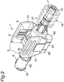
Fig. 2 is a perspective view illustrating the flush device according to the first embodiment of the present invention. -
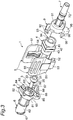
Fig. 3 is an assembly view illustrating the flush device according to the first embodiment of the present invention. -
Fig. 4 is a plan view illustrating the flush device according to the first embodiment of the present invention. -
Fig. 5 is a side view illustrating the flush device according to the first embodiment of the present invention. -
Fig. 6 is a front view illustrating the flush device according to the first embodiment of the present invention. -
Fig. 7 is a cross-sectional view taken along line A-A and viewed in a direction of the arrow inFig. 6 . -
Fig. 8 is a perspective view illustrating a first housing. -
Fig. 9 is a perspective view illustrating a second housing. -
Fig. 10 is a perspective view illustrating a flow control device. -
Fig. 11 is a perspective view illustrating the flow control device. -
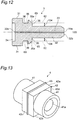
Fig. 12 is a cross-sectional view illustrating the flow control device. -
Fig. 13 is a perspective view illustrating an elastic member. -
Fig. 14 is a perspective view illustrating a pair of wings. -
Fig. 15 is a perspective view illustrating the pair of wings. -
Fig. 16 is a view corresponding toFig. 6 , illustrating a state in which a pair of wings is displaced. -
Fig. 17 is a view corresponding toFig. 7 , illustrating a state in which a pair of wings is displaced. -
Fig. 18 is a diagram illustrating an irrigation line provided with a flush device according to a second embodiment of the present invention. -
Fig. 19 is a perspective view illustrating another example of the elastic member. -
Fig. 20 is a front view illustrating the flush device according to the second embodiment of the present invention. -
Fig. 21 is a cross-sectional view taken along line A-A and viewed in a direction of the arrow inFig. 20 . -
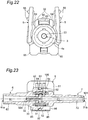
Fig. 22 is a view corresponding toFig. 20 , illustrating a state in which a pair of wings is displaced. -
Fig. 23 is a view corresponding toFig. 21 , illustrating a state in which a pair of wings is displaced. - Hereinafter, embodiments of the present invention will be specifically described with reference to the accompanying drawings.
-
Fig. 1 illustrates anirrigation line 10 provided with aflush device 1 according to a first embodiment of the present invention. Theirrigation line 10 includes abottle needle 11, apressure transducer 12, a three-way stopcock 13, aconnector 14, and the like, along with theflush device 1. Thebottle needle 11 and theflush device 1 are connected to each other with atube 15, and the three-way stopcock 13 and theconnector 14 are connected to each other with atube 16. Theflush device 1, thepressure transducer 12, and the three-way stopcock 13 may be directly connected to each other. Theconnector 14 is connected to a chemical liquid source (not shown). - The
irrigation line 10 provided with thepressure transducer 12 may be particularly referred to as a pressure monitoring tube set. However, in the present specification, theirrigation line 10 may not include thepressure transducer 12. Theirrigation line 10 may be used for invasive blood pressure measurement and cerebrospinal fluid pressure measurement during surgery. - The
pressure transducer 12 is connected to acontroller 17. Thepressure transducer 12 converts blood pressure or fluid pressure transmitted through thebottle needle 11 and thetube 15 into an electric signal and transmits it to thecontroller 17. Thecontroller 17 includes a CPU (central processing unit), a memory, a monitor, and the like, and is configured to digitally process the transmitted electric signal and display the blood pressure or the fluid pressure on the monitor. While in the present embodiment, thepressure transducer 12 is attached detachably from theirrigation line 10, it may be integrated with theirrigation line 10. - As illustrated in
Figs. 2 to 7 , theflush device 1 includes a casing 2, aflow control device 3, anelastic member 4, and a pair ofwings flush device 1 is configured to contiguously discharge a small amount of chemical liquid through theflow control device 3. Theflow control device 3 and theelastic member 4 are accommodated in the casing 2. The pair ofwings Figs. 2 to 7 illustrate theflush device 1 with the pair ofwings - The casing 2, the
flow control device 3, and the pair ofwings elastic member 4 may be made of an elastomeric material, such as silicone. - In the following description of the
flush device 1, a chemical liquid source side of a position where theflush device 1 is disposed in theirrigation line 10 is referred to as an upstream side, and abottle needle 11 side of a position where theflush device 1 is disposed in theirrigation line 10 is referred to as a downstream side. For convenience, two directions perpendicular to the direction extending from the upstream side to the downstream side (longitudinal direction) can be defined, one direction extending through the pair ofwings - The casing 2 includes a
first housing 6 and asecond housing 7 that are coupled to each other. Thefirst housing 6 is disposed on the upstream side, and thesecond housing 7 is disposed on the downstream side. - As illustrated in
Figs. 7 and8 , thefirst housing 6 includes anelongated body 62 having afirst flow path 61 inside. Thefirst flow path 61 has acentral axis 101, and thebody 62 of thefirst housing 6 extends along thecentral axis 101. In thefirst housing 6, the direction in which thecentral axis 101 extends is referred to as an axial direction of thefirst housing 6, and any direction orthogonal to the axial direction is referred to as a radial direction of thefirst housing 6. - The
first flow path 61 extends in a tapered shape from the upstream side to the downstream side. Thefirst flow path 61 is provided at one end (upstream end) with aninlet 61a, and at the other end (downstream end) with anoutlet 61b. Theinlet 61a of thefirst flow path 61 serves as an inlet of theflush device 1. Theinlet 61a of thefirst flow path 61 is circular. Theoutlet 61b of thefirst flow path 61 is formed crisscross (in a cross shape). Thebody 62 has adownstream end portion 63 defining theoutlet 61b of thefirst flow path 61, to which theflow control device 3 is attached. Theoutlet 61b formed crisscross includes a hole extending in the vertical direction, the hole communicating with upper andlower slot grooves body 62. Theslot grooves body 62. - The
downstream end portion 63 of thefirst housing 6 includes a plurality ofholes 65 provided on an inner periphery defining thefirst flow path 61 of thebody 62. Thehole 65 function as a fitting receiving portion for fitting and fixing theflow control device 3 to thefirst housing 6. Thehole 65 have a rectangular shape when viewed laterally. The plurality ofholes 65 is preferably provided at equal intervals in a circumferential direction. In the present embodiment, twoholes 65 are provided on the left and right sides at 180 degree intervals. In the present embodiment, thehole 65 is a through hole passing through the peripheral wall of thebody 62 in the radial direction. In another embodiment, thehole 65 may be a non-through (blind) hole that does not pass through the peripheral wall of thebody 62 in the radial direction. Here, a part of the peripheral wall of thebody 62, located on the downstream side of thehole 65, is referred to as aspacer receiving portion 66. - The
body 62 of thefirst housing 6 is provided at its upstream end with amale connector 67. Themale connector 67 can be attached to a female connector (not shown) provided in thepressure transducer 12 illustrated inFig. 1 . - As illustrated in
Figs. 7 and9 , thesecond housing 7 includes anelongated body 72 having asecond flow path 71 inside. Thesecond flow path 71 has acentral axis 102, and thebody 72 of thesecond housing 7 extends along thecentral axis 102. In thesecond housing 7, the direction in which thecentral axis 102 extends is referred to as an axial direction of thesecond housing 7, and any direction in a plane orthogonal to the axial direction is referred to as a radial direction of thesecond housing 7. Thecentral axis 102 of thesecond flow path 71 extends along thecentral axis 101 of thefirst flow path 61. Thecentral axis 102 of thesecond flow path 71 and thecentral axis 101 of thefirst flow path 61 may not extend completely in one straight line. Both thecentral axes - The
second flow path 71 extends in a tapered shape from the upstream side to the downstream side. Thesecond flow path 71 is provided at one end (upstream end) with aninlet 71a, and at the other end (downstream end) with anoutlet 71b. Theinlet 71a and theoutlet 71b of thesecond flow path 71 are circular. Theoutlet 71b of thesecond flow path 71 serves as an outlet of theflush device 1. Thebody 72 has anupstream end portion 73 that defines theinlet 71a of thesecond flow path 71 and that is located close to theflow control device 3. - As illustrated in
Fig. 2 , afemale connector 18 is attached to a downstream end portion of thebody 72 of thesecond housing 7. Thefemale connector 18 is attached to a male connector (not illustrated) provided in thetube 15 illustrated inFig. 1 . - The
first housing 6 and thesecond housing 7 are coupled to each other by means of a coupling mechanism. In the present embodiment, the coupling mechanism includes afirst coupler 8 provided at the downstream end of thefirst housing 6 and asecond coupler 9 provided at the upstream end of thesecond housing 7. - As illustrated in
Fig. 8 , thefirst coupler 8 includes acup portion 81 that opens on the downstream side in the axial direction. Thecup portion 81 is provided on its downstream end with an L-shapedplate 82 as viewed from the side. Theplate 82 includes avertical plate 82a extending in the vertical direction and ahorizontal plate 82b extending downstream in the axial direction. Thehorizontal plate 82b has a T-shapedend face 82c as viewed from the downstream side in the axial direction. Thehorizontal plate 82b is provided on its lower side with atongue portion 83 extending axially downstream from thevertical plate 82a. Thetongue portion 83 is provided at its downstream end with afitting claw 83a protruding upward. Thetongue portion 83 is provided in its upper surface with a recessed portion defined by thehorizontal plate 82b and thefitting claw 83a. This recessed portion is referred to as abridge receiving portion 84. - The
cup portion 81 is provided in its lower downstream end with apanel 85. Thepanel 85 includes ahorizontal plate 86 extending downstream in the axial direction. Thehorizontal plate 86 is provided on its upper side with atongue portion 87 extending downstream in the axial direction from thepanel 85. Thetongue portion 87 is provided at its downstream end with afitting claw 87a protruding downward. Thepanel 85 includes a pair of circular shaft holes 88, 88 located laterally on both side of thehorizontal plate 86 and thetongue portion 87. - As illustrated in
Fig. 9 , thesecond coupler 9 includes acup portion 91 that opens on the upstream side in the axial direction. Thecup portion 91 is provided in its upper upstream end portion with a pair ofbeams cup portion 91 and that extend upstream in the axial direction. The pair ofbeams tongue portion 83 of thefirst coupler 8 in such a manner to interpose and engage with thetongue portion 83 when thefirst housing 6 and thesecond housing 7 are coupled to each other. - The
second coupler 9 includes abridge 93 connecting thebeams first housing 6 is coupled to thesecond housing 7, thefitting claw 83a is fitted (snap-fitted) on the downstream side of thebridge 93. Then, thebridge 93 has a longitudinal dimension equivalent to a longitudinal dimension (or length) of thebridge receiving portion 84 in such a manner to fit into thebridge receiving portion 84 of thefirst coupler 8. As described above, thebridge 93 functions as a claw receiving portion that receives thefitting claw 83a. - On the upstream side of the
bridge 93, only lower portions of thebeams arms arms horizontal plate 82b when thefirst housing 6 is coupled to thesecond housing 7. As described above, thehorizontal plate 82b receives thearms first housing 6 with respect to thesecond housing 7. In a preferred embodiment, thearms vertical plate 82a of theplate 82. - The
cup portion 91 is provided in its lower downstream end with apanel 95. Thepanel 95 includes a pair ofbeams beams tongue portion 87 of thefirst coupler 8 in such a manner to interpose and engage with thetongue portion 87 when thefirst housing 6 and thesecond housing 7 are coupled to each other. - The
second coupler 9 includes aninclined wall 97 provided between thebeams inclined wall 97 extends obliquely upward with respect to the longitudinal direction as going from the upstream side toward the downstream side. When thefirst housing 6 is coupled to thesecond housing 7, thefitting claw 87a is fitted (snap-fitted) on a downstream side of theinclined wall 97. As described above, theinclined wall 97 functions as a claw receiving portion that receives thefitting claw 83a. - The
beams beams arms arms horizontal plate 86 and thetongue portion 87 when thefirst housing 6 is coupled to thesecond housing 7. As described above, thehorizontal plate 86 and thetongue portion 87 work together to receive thearms first housing 6 with respect to thesecond housing 7. In a preferred embodiment, thearms panel 85. Thepanel 95 includes a pair of circular shaft holes 99, 99 located laterally on both side of thebeams - The
flow control device 3 includes abase 31 and aprotrusion 32 extending from thebase 31. Thebase 31 has a diameter larger than a diameter of theprotrusion 32. As illustrated inFigs. 10 and 11 , in the present embodiment, thebase 31 and theprotrusion 32 each have a columnar shape. Thebase 31 is located between thefirst flow path 61 and thesecond flow path 71. Theprotrusion 32 has abase end 32a on a side of thebase 31 and aleading end 32b on the side opposite to thebase end 32a. Most of theprotrusion 32 including theleading end 32b is located inside thefirst flow path 61. Thebase 31 includes a recessedportion 34. Theprotrusion 32 is disposed with apredetermined interval 104 away from the inner periphery of thebody 62 of the first housing 6 (SeeFig. 12 ). - The
flow control device 3 is attached to thedownstream end portion 63 of thefirst housing 6. Thebase 31 has a dimension (diameter) to completely cover a downstream end face of thefirst housing 6 as theflow control device 3 is attached to thedownstream end portion 63 of thefirst housing 6. The base 31 preferably has a diameter substantially equivalent to a diameter of thedownstream end portion 63 of thefirst housing 6. - The
flow control device 3 is provided with a throughhole 33 extending through thebase 31 and theprotrusion 32. The throughhole 33 has such an inner diameter as to function as a capillary. Theflush device 1 discharges a chemical liquid at a flow rate that decreases with decrease in diameter of the throughhole 33 and with increase in length thereof. The throughhole 33 has acentral axis 103, and theprotrusion 32 extends along thecentral axis 103. In theflow control device 3, a direction in which thecentral axis 103 extends is referred to as an axial direction of theflow control device 3, and any direction in a plane orthogonal to the axial direction is referred to as a radial direction of theflow control device 3. Thecentral axis 103 of the throughhole 33 extends along thecentral axis 101 of the first flow path 61 (and thecentral axis 102 of the second flow path 71). Thecentral axis 103 of the throughhole 33 may not extend completely in one straight line with thecentral axis 101 of the first flow path 61 (and thecentral axis 102 of the second flow path 71). Thecentral axes - The through
hole 33 connects thefirst flow path 61 and thesecond flow path 71 in fluid communication in theflush device 1. The throughhole 33 has aninlet 33a and anoutlet 33b. Theinlet 33a communicates with thefirst flow path 61 provided in thefirst housing 6, and theoutlet 33b communicates with thesecond flow path 71 provided in thesecond housing 7. - In the
flow control device 3, theprotrusion 32 is provided on its outer periphery with a plurality offitting projections 35 projecting radially outward. Thefitting projections 35 are fitted (snap-fitted) into the correspondingholes 65 provided in thefirst housing 6, so that theflow control device 3 is fixed to thefirst housing 6. When the plurality ofholes 65 are provided at equal intervals in the circumferential direction, the plurality offitting projections 35 are also provided at equal intervals in the circumferential direction. The number of thefitting projections 35 may be equal to that of theholes 65. Thefitting projections 35 each have a shape complementary to thehole 65, and in the present embodiment, each have a shape similar to a rectangular parallelepiped. However, thefitting projections 35 are each provided with aninclined surface 35a to facilitate fitting of thefitting projections 35 into the corresponding holes 65. - In the
flow control device 3, a plurality ofspacers 36 are provided on the outer periphery of theprotrusion 32 and on the side of thebase end 32a of the plurality offitting projections 35. Thespacers 36 each have a rectangular parallelepiped shape. Thespacers 36 each protrude radially outward from the outer periphery of theprotrusion 32 toward the inner periphery defining thefirst flow path 61. - In the present embodiment, two
spacers 36 are provided on the left and right sides at 180 degree intervals apart from each other, as twoholes 65 are provided on the left and right sides at 180 degree intervals apart from each other. In addition, in the present embodiment, the plurality ofspacers 36 each butt the inner periphery defining thefirst flow path 61. It is preferable that the plurality ofspacers 36 each have such a dimension as to butt and bump the inner periphery. In another embodiment, a predetermined interval may exist between a radially outer end of each of the plurality ofspacers 36 and the inner periphery. - As illustrated in
Fig. 13 , theelastic member 4 includes atubular portion 41 and ablock portion 42 provided around thetubular portion 41. Thetubular portion 41 is provided around thebase 31 of theflow control device 3. Thetubular portion 41 includes ahollow portion 41a in which thebase 31 and thedownstream end portion 63 of thefirst housing 6 are biased to be accommodated. This can seal off a space between thefirst flow path 61 and thesecond flow path 71, and thefirst flow path 61 is connected to thesecond flow path 71 in fluid communication only via the throughhole 33. When thebase 31 and thedownstream end portion 63 of thefirst housing 6 each have an approximately equal diameter, theelastic member 4 can suitably accommodate them. Theelastic member 4 is biased to be held between the upper andlower tongue portions first coupler 8 on the upstream side, and is biased to be held between the upper andlower arms second coupler 9 on the downstream. - The
block portion 42 has a square shape when viewed in the axial direction. Theblock portion 42 includes anupper surface 42a and alower surface 42b that are respectively in contact with the upper andlower tongue portions first coupler 8, andside surfaces upper surface 42a and thelower surface 42b. Theblock portion 42 is provided at its axially central portion with abump 43 throughout the circumference thereof. Thebump 43 is provided integrally with theblock portion 42. When the casing 2 is made of a transparent or translucent material, thebump 43 is viewed from the outside to function as a positioning marker for checking whether theelastic member 4 is disposed at a correct position. The side surfaces 42c, 42d of theblock portion 42 are partially exposed to the pair ofwings - The
elastic member 4 is configured to be deformed when receiving a force from the pair ofwings elastic member 4 and the outer periphery of thebase 31 of theflow control device 3. This can create a bypass flow path 105 (SeeFig. 17 ) for further fluid connection between thefirst flow path 61 and thesecond flow path 71. - The pair of right and
left wings elastic member 4. Thewings Figs. 15 and16 , each of thewings body 51, acylindrical shaft portion 52 that is provided at the bottom of thebody 51 and that extends parallel to thecentral axis 101, and a connectingportion 53 for connecting thebody 51 and theshaft portion 52. The connectingportion 53 extends obliquely with respect to thebody 51 when viewed in the axial direction. - The
shaft portion 52 is inserted into the shaft hole 89 of thefirst coupler 8 and theshaft hole 99 of thesecond coupler 9. Theshaft portion 52 has a diameter slightly smaller than a diameter of each of the shaft holes 89 and 99. Theshaft portion 52 and the shaft hole 89 form a hinge mechanism. In this way the pair ofwings first housing 6 and thesecond housing 7 so as to rotate around eachshaft portion 52. In another embodiment, a hinge mechanism may be formed by providing a protrusion on each of thefirst coupler 8 and thesecond coupler 9 and fitting the protrusion to a recessed portion each provided on the shaft members. - The
body 51 is provided on its inner surface with apressing portion 54. Thepressing portion 54 is a protrusion that can press each of the side surfaces 42c, 42d of theblock portion 42 of theelastic member 4 when the pair ofwings shaft portions elastic member 4. In the present embodiment, thepressing portion 54 presses an upper portion of each of the side surfaces 42c and 42d of theblock portion 42. Thebody 51 is provided on its outer surface with aknob 55 that is a protrusion extending along the axial direction, thereby allowing a user to easily operate the pair ofwings - As illustrated in
Figs. 16 and 17 , when the user pinches and rotates the pair ofwings elastic member 4, upper portions of the side surfaces 42c, 42d of theelastic member 4 are pressed. Then, theupper surface 42a of theelastic member 4 is deformed so as to form an upwardly convex curved surface. This can form abypass flow path 105 for a chemical liquid, connected from thefirst flow path 61 to thesecond flow path 71 through theupper slot groove 64, and a larger amount of chemical liquid can pass through thebypass flow path 105. In this way theflush device 1 can discharge and quickly flush more chemical liquid. - With reference to
Fig. 3 , a method for assembling theflush device 1 will be described. First, thefitting projection 35 of theflow control device 3 is fitted (snap-fitted) into thehole 65 of thefirst housing 6, so that theflow control device 3 is fixed to thefirst housing 6. This allows theflow control device 3 to be positioned in the radial direction and the axial direction, thereby thecentral axis 103 of the throughhole 33 of theflow control device 3 extending along thecentral axis 101 of thefirst flow path 61. In the present embodiment, when thefitting projection 35 is fitted into thehole 65, the plurality ofspacers 36 each butt the inner periphery defining thefirst flow path 61. This allows theflow control device 3 to be more reliably fixed to thefirst housing 6, so that theflow control device 3 is positioned with higher accuracy in the radial direction and the axial direction. When theflow control device 3 is fixed to thefirst housing 6, theoutlet 61b of thefirst flow path 61 is covered with thebase 31 of theflow control device 3. - Next, the
base 31 of theflow control device 3 and thedownstream end portion 63 of thefirst housing 6 are inserted into thehollow portion 41a of thetubular portion 41 of theelastic member 4. Theelastic member 4 is held between the upper andlower tongue portions first coupler 8 on the upstream side, and is held between the upper andlower arms second coupler 9 on the downstream side. This allows theflow control device 3 to be more reliably fixed to thefirst housing 6, so that theflow control device 3 is positioned with higher accuracy in the radial direction and the axial direction. At this time, it is checked that theelastic member 4 is disposed at a correct position (in the present embodiment, the position of thebase 31 of the flow control device 3) by observing the position of thebump 43 provided on theblock portion 42 of theelastic member 4 from the outside. - Next, the
first housing 6 is coupled to thesecond housing 7. Specifically, thefitting claws 83a are fitted to the downstream side of the bridge 93 (snap fitted) while theshaft portions panel 85 and the corresponding shaft holes 99, 99 of thepanel 95, and thus thebridge receiving portion 84 of thefirst coupler 8 is fitted to thebridge 93 of thesecond coupler 9. In this manner, thefirst housing 6 is coupled to thesecond housing 7, and thesecond housing 7 is positioned with respect to thefirst housing 6 in the radial direction and the axial direction, thereby thecentral axis 102 of thesecond flow path 71 extending along thecentral axis 101 of thefirst flow path 61. - When the
first housing 6 is coupled to thesecond housing 7, theupper beams second coupler 9 interpose and engage with theupper tongue portion 83 of thefirst coupler 8, and thelower beams second coupler 9 interpose and engage with thelower tongue portion 87 of thefirst coupler 8. This allows thesecond housing 7 to be further positioned in the radial direction with respect to thefirst housing 6. - When the
first housing 6 is coupled to thesecond housing 7, thearms second coupler 9 are further fitted into the respective corners of the T-shape of thehorizontal plate 82b of thefirst coupler 8, and thelower arms second coupler 9 are fitted into the respective corners formed by thehorizontal plate 86 and thetongue portion 87 of thefirst coupler 8. Accordingly, even when a force bending or twisting the casing 2 is applied, relative rotation of thefirst housing 6 with respect to thesecond housing 7 is restricted by thehorizontal plate 82b on the upper side and thehorizontal plate 86 and thetongue portion 87 on the lower side, and thus thesecond housing 7 is hardly displaced with respect to thefirst housing 6. - In a preferred embodiment, when the
first housing 6 is coupled to thesecond housing 7, thearms second coupler 9 butt the downstream surface of thevertical plate 82a of theplate 82, and thelower arms second coupler 9 butt the downstream surface of thepanel 85. This allows thesecond housing 7 to be further positioned in the axial direction with respect to thefirst housing 6. - Here, when the
central axis 103 of the throughhole 33 of theflow control device 3 extends more linearly with both thecentral axis 101 of thefirst flow path 61 of thefirst housing 6 and thecentral axis 102 of thesecond flow path 71 of thesecond housing 7, a flow rate of the chemical liquid discharged from theflow control device 3 can be made closer to a defined amount. - In the
flush device 1 according to the above-described embodiment, theflow control device 3 can be positioned so that thecentral axis 103 of theflow control device 3 extends along thecentral axis 101 of thefirst flow path 61. In addition, thesecond housing 7 can be positioned with respect to thefirst housing 6 so that thecentral axis 102 of thesecond flow path 71 extends along thecentral axis 101 of thefirst flow path 61. In this manner, theflush device 1 capable of discharging the chemical liquid at a flow rate close to the defined amount can be realized. - In the
flush device 1 according to the above-described embodiment, theflow control device 3 is fixed to thefirst housing 6 only by means of a mechanical joint (coupling mechanism) without forming a joint by adhesion or welding. The same applies to fixing of thesecond housing 7 to thefirst housing 6. In this manner, in the above-described embodiment, theflush device 1 can be more easily assembled. However, in another embodiment, a joint formed by adhesion or welding may be provided in addition to these mechanical joints. -
Fig. 18 is a diagram illustrating an irrigation line provided with a flush device according to a second embodiment of the present invention.Fig. 19 is a perspective view illustrating another example of the elastic member. The flush device according to the second embodiment employs anelastic member 4a having a cylindrical shape instead of theelastic member 4 including theblock portion 42. Other configurations are the same as those of the flush device according to the first embodiment, and thus duplicated description will be eliminated. - As illustrated in
Fig. 19 , theelastic member 4a includes atubular portion 41 provided with ahollow portion 41a, and is made of, for example, an elastomeric material such as silicone. As illustrated inFigs. 20 and 21 , theelastic member 4a is provided around thebase 31 of theflow control device 3, and thebase 31 and thedownstream end portion 63 of thefirst housing 6 are biased to be accommodated in thehollow portion 41a. This can seal off a space between thefirst flow path 61 and thesecond flow path 71, and thefirst flow path 61 is connected to thesecond flow path 71 in fluid communication only via the throughhole 33. When thebase 31 has a diameter approximately equal to a diameter of thedownstream end portion 63 of thefirst housing 6, theelastic member 4a can appropriately accommodate them. - As illustrated in
Figs. 22 and 23 , as for the operation of theelastic member 4a, when a user pinches and rotates the pair ofwings elastic member 4a, the side surface of theelastic member 4a is pressed, so that an upper portion of theelastic member 4a is deformed so as to form an upwardly convex curved surface, thereby forming a gap between the inner periphery of theelastic member 4a and the outer periphery of thebase 31 of theflow control device 3. This can form abypass flow path 105 for a chemical liquid, connected from thefirst flow path 61 to thesecond flow path 71 through theupper slot groove 64, and a larger amount of chemical liquid can pass through thebypass flow path 105. In this way theflush device 1 can discharge and quickly flush more chemical liquid. - Similar procedure to that in the first embodiment can be used for assembling the flush device.
- It should not be understood that the present invention is limited to the above-described embodiments. In addition, other embodiments may be configured by freely combining the features described in the above-described embodiments. Further, various improvements, changes and deletions in design may be applied to the above-described embodiments.
- For example, a structure corresponding to the
first coupler 8 may be provided in thesecond housing 7 and a structure corresponding to thesecond coupler 9 may be provided in thefirst housing 6. This configuration can also obtain effects similar to those in the above-described embodiments. -
- 1 FLUSH DEVICE
- 2 CASING
- 3 FLOW CONTROL DEVICE
- 31 BASE
- 32 PROTRUSION
- 32a BASE END (OF PROTRUSION)
- 32b LEADING END (OF PROTRUSION)
- 33 THROUGH HOLE
- 35 FITTING PROJECTION
- 36 SPACER
- 4, 4a ELASTIC MEMBER
- 41 TUBULAR PORTION
- 42 BLOCK PORTION
- 43 BUMP
- 5 WING
- 52 SHAFT PORTION
- 54 PRESSING PORTION
- 6 FIRST HOUSING
- 61 FIRST FLOW PATH
- 62 BODY (OF FIRST HOUSING)
- 63 DOWNSTREAM END PORTION (OF FIRST HOUSING)
- 65 HOLE
- 7 SECOND HOUSING
- 71 SECOND FLOW PATH
- 72 BODY (OF SECOND HOUSING)
- 73 UPSTREAM END PORTION (OF SECOND HOUSING)
- 8 FIRST COUPLER
- 9 SECOND COUPLER
- 10 IRRIGATION LINE
- 12 PRESSURE TRANSDUCER
- 101 CENTRAL AXIS (OF FIRST HOUSING)
- 102 CENTRAL AXIS (OF SECOND HOUSING)
- 103 CENTRAL AXIS (OF FLOW CONTROL DEVICE)
- 104 INTERVAL BETWEEN PROTRUSION AND INNER PERIPHERY OF FIRST HOUSING
- 105 BYPASS FLOW PATH
Claims (8)
- A flush device comprising:a first housing provided with a first flow path having a central axis;a second housing provided with a second flow path extending along the central axis, the second housing being coupled to the first housing;a flow control device including:- a base located between the first flow path and the second flow path;- a protrusion having a base end on a side of the base and a leading end located inside the first flow path, the protrusion extending along a central axis from the base end toward the leading end; and- a through hole extending along the central axis through both the base and the protrusion to connect the first flow path to the second flow path in fluid communication; andan elastic member provided around the base of the flow control device to seal off a space between the first flow path and the second flow path;wherein the elastic member is configured to be deformable to form a gap between the elastic member and an outer periphery of the base of the flow control device, thereby forming a bypass flow path for further fluid communication between the first flow path and the second flow path,the protrusion of the flow control device is provided on its outer periphery with a plurality of fitting projections, andthe first housing has an inner periphery defining the first flow path, the inner periphery being provided with a plurality of fitting receiving portions each being fitted to each of the plurality of fitting projections.
- The flush device according to Claim 1, wherein the protrusion is disposed with a predetermined interval away from the inner periphery defining the first flow path, and
a plurality of spacers are provided on the outer periphery of the protrusion and on the side of the base end of the plurality of fitting projections in the flow control device. - The flush device according to Claim 2, wherein the plurality of spacers each butt the inner periphery defining the first flow path.
- The flush device according to any one of Claims 1 to 3, wherein the first housing is coupled to the second housing by means of a coupling mechanism, and
the coupling mechanism includes a claw provided at an end of one of the first housing and the second housing, and a claw receiving portion provided at an end of the other of the first housing and the second housing, the claw receiving portion being fitted to the claw. - The flush device according to Claim 4, wherein the coupling mechanism includes an arm extending from the claw receiving portion toward one of the first housing and the second housing, and an arm receiving portion provided at an end of one of the first housing and the second housing to receive the arm for restricting relative rotation of the first housing with respect to the second housing.
- The flush device according to any one of Claims 1 to 5, further comprising a pair of wings, the pair of wings each including:a shaft portion extending parallel to the central axis, the pair of wings each being supported by the first housing and the second housing so as to rotate around the shaft portion; anda pressing portion for pressing and deforming the elastic member.
- The flush device according to any one of Claims 1 to 6, wherein the elastic member includes a positioning marker provided integrally with the elastic member.
- An irrigation line comprising:
the flush device according to any one of Claims 1 to 7.
Applications Claiming Priority (2)
| Application Number | Priority Date | Filing Date | Title |
|---|---|---|---|
| JP2017216698 | 2017-11-09 | ||
| PCT/JP2018/033625 WO2019092979A1 (en) | 2017-11-09 | 2018-09-11 | Flush device and irrigation line |
Publications (4)
| Publication Number | Publication Date |
|---|---|
| EP3708217A1 true EP3708217A1 (en) | 2020-09-16 |
| EP3708217A4 EP3708217A4 (en) | 2021-08-11 |
| EP3708217C0 EP3708217C0 (en) | 2026-05-06 |
| EP3708217B1 EP3708217B1 (en) | 2026-05-06 |
Family
ID=66438285
Family Applications (1)
| Application Number | Title | Priority Date | Filing Date |
|---|---|---|---|
| EP18875996.3A Active EP3708217B1 (en) | 2017-11-09 | 2018-09-11 | Flush device and irrigation line |
Country Status (5)
| Country | Link |
|---|---|
| US (1) | US11690572B2 (en) |
| EP (1) | EP3708217B1 (en) |
| JP (1) | JP7279638B2 (en) |
| CN (1) | CN111278502B (en) |
| WO (1) | WO2019092979A1 (en) |
Families Citing this family (1)
| Publication number | Priority date | Publication date | Assignee | Title |
|---|---|---|---|---|
| CN112604057A (en) * | 2020-12-24 | 2021-04-06 | 上海康尔康健康管理有限公司 | Intestinal tract cleaning equipment and method |
Family Cites Families (11)
| Publication number | Priority date | Publication date | Assignee | Title |
|---|---|---|---|---|
| US4278083A (en) * | 1978-06-29 | 1981-07-14 | Young James E | Flow regulating device for arterial catheter systems |
| US4192303A (en) | 1978-06-29 | 1980-03-11 | Walker Ralph S | Flow regulating device for arterial catheter systems |
| US4718634A (en) | 1986-09-23 | 1988-01-12 | Hewlett-Packard Company | Physiological pressure monitoring system flush valve |
| US4934375A (en) | 1988-03-04 | 1990-06-19 | Spectramed, Inc. | Flush-valve assembly for blood pressure measurement catheter |
| EP0331526B1 (en) * | 1988-03-04 | 1993-02-10 | Spectramed, Inc. | Improved flush-valve assembly for blood pressure measurement catheter |
| US5820565A (en) * | 1996-11-04 | 1998-10-13 | Merit Medical System, Inc. | Flush valve with interlocking seal |
| DE10326683B4 (en) * | 2003-06-03 | 2005-11-03 | Telegärtner Kunststofftechnik GmbH | Flow control device for medical applications |
| WO2007083599A1 (en) * | 2006-01-17 | 2007-07-26 | Jms Co., Ltd. | Water passage control device and medical infusion circuit using the same |
| US7959192B2 (en) * | 2008-07-09 | 2011-06-14 | Pall Corporation | Disconnectable connector assembly |
| FR3007813B1 (en) * | 2013-06-28 | 2016-01-01 | Sartorius Stedim Biotech | FLUIDIC CONNECTOR WITH COLLAR AND PROTECTION. |
| WO2016051759A1 (en) * | 2014-09-29 | 2016-04-07 | テルモ株式会社 | Female connector, male connector, and connector connection body |
-
2018
- 2018-09-11 WO PCT/JP2018/033625 patent/WO2019092979A1/en not_active Ceased
- 2018-09-11 US US16/762,287 patent/US11690572B2/en active Active
- 2018-09-11 EP EP18875996.3A patent/EP3708217B1/en active Active
- 2018-09-11 CN CN201880072515.9A patent/CN111278502B/en active Active
- 2018-09-11 JP JP2019551900A patent/JP7279638B2/en active Active
Also Published As
| Publication number | Publication date |
|---|---|
| WO2019092979A1 (en) | 2019-05-16 |
| JPWO2019092979A1 (en) | 2020-11-26 |
| CN111278502B (en) | 2022-07-26 |
| EP3708217C0 (en) | 2026-05-06 |
| JP7279638B2 (en) | 2023-05-23 |
| EP3708217B1 (en) | 2026-05-06 |
| US11690572B2 (en) | 2023-07-04 |
| CN111278502A (en) | 2020-06-12 |
| US20200352512A1 (en) | 2020-11-12 |
| EP3708217A4 (en) | 2021-08-11 |
Similar Documents
| Publication | Publication Date | Title |
|---|---|---|
| JP6430628B2 (en) | Pressure output device for extracorporeal hemodialysis machine | |
| US11185259B2 (en) | Smart obturator with sensor and smart obturator assembly | |
| US20230143159A1 (en) | Smart obturator assembly | |
| EP2022519A1 (en) | Device for detecting a pressure change in the liquid path of a micro dosing apparatus | |
| JP2002282361A (en) | Electro-fluid disposable connector with data retention | |
| CN219997089U (en) | All-in-one kit | |
| EP3708217B1 (en) | Flush device and irrigation line | |
| US11357899B2 (en) | Measuring device and method for measuring a property of a fluid in a line | |
| CN107847728B (en) | Medical connector with two valves | |
| US7614423B2 (en) | Connector | |
| KR102098545B1 (en) | Flow measuring tube for ultrasonic flow meter, transfusion tube with flow measuring tube and ultrasonic flow measuring system | |
| EP2868337A1 (en) | Fluid transport apparatus, fluid infusing apparatus, and trouble determining method for transporting tube | |
| TW202519274A (en) | Tubing connector | |
| TW202519275A (en) | Tubing connector | |
| JP2019063449A (en) | Flow regulation device, flush device, and irrigation line | |
| US20150258321A1 (en) | Sealing connector assembly | |
| US8894629B2 (en) | High flow catheter valve | |
| CN118776724A (en) | Pressure detection device and medical pump | |
| BR112020004497B1 (en) | SMART SHUTTER ASSEMBLY |
Legal Events
| Date | Code | Title | Description |
|---|---|---|---|
| STAA | Information on the status of an ep patent application or granted ep patent |
Free format text: STATUS: THE INTERNATIONAL PUBLICATION HAS BEEN MADE |
|
| PUAI | Public reference made under article 153(3) epc to a published international application that has entered the european phase |
Free format text: ORIGINAL CODE: 0009012 |
|
| STAA | Information on the status of an ep patent application or granted ep patent |
Free format text: STATUS: REQUEST FOR EXAMINATION WAS MADE |
|
| 17P | Request for examination filed |
Effective date: 20200609 |
|
| AK | Designated contracting states |
Kind code of ref document: A1 Designated state(s): AL AT BE BG CH CY CZ DE DK EE ES FI FR GB GR HR HU IE IS IT LI LT LU LV MC MK MT NL NO PL PT RO RS SE SI SK SM TR |
|
| AX | Request for extension of the european patent |
Extension state: BA ME |
|
| DAV | Request for validation of the european patent (deleted) | ||
| DAX | Request for extension of the european patent (deleted) | ||
| A4 | Supplementary search report drawn up and despatched |
Effective date: 20210709 |
|
| RIC1 | Information provided on ipc code assigned before grant |
Ipc: A61M 39/22 20060101AFI20210705BHEP Ipc: A61B 5/0215 20060101ALI20210705BHEP Ipc: A61B 5/03 20060101ALI20210705BHEP Ipc: A61M 5/168 20060101ALI20210705BHEP |
|
| STAA | Information on the status of an ep patent application or granted ep patent |
Free format text: STATUS: EXAMINATION IS IN PROGRESS |
|
| 17Q | First examination report despatched |
Effective date: 20240221 |
|
| REG | Reference to a national code |
Ref country code: DE Free format text: PREVIOUS MAIN CLASS: A61M0039220000 Ref legal event code: R079 Ref document number: 602018091235 Country of ref document: DE Ipc: A61M0005140000 |
|
| GRAP | Despatch of communication of intention to grant a patent |
Free format text: ORIGINAL CODE: EPIDOSNIGR1 |
|
| STAA | Information on the status of an ep patent application or granted ep patent |
Free format text: STATUS: GRANT OF PATENT IS INTENDED |
|
| RIC1 | Information provided on ipc code assigned before grant |
Ipc: A61M 5/168 20060101ALI20251212BHEP Ipc: A61M 39/22 20060101ALI20251212BHEP Ipc: A61M 5/14 20060101AFI20251212BHEP |
|
| INTG | Intention to grant announced |
Effective date: 20260107 |
|
| GRAS | Grant fee paid |
Free format text: ORIGINAL CODE: EPIDOSNIGR3 |
|
| GRAA | (expected) grant |
Free format text: ORIGINAL CODE: 0009210 |
|
| STAA | Information on the status of an ep patent application or granted ep patent |
Free format text: STATUS: THE PATENT HAS BEEN GRANTED |
|
| AK | Designated contracting states |
Kind code of ref document: B1 Designated state(s): AL AT BE BG CH CY CZ DE DK EE ES FI FR GB GR HR HU IE IS IT LI LT LU LV MC MK MT NL NO PL PT RO RS SE SI SK SM TR |
|
| REG | Reference to a national code |
Ref country code: CH Ref legal event code: F10 Free format text: ST27 STATUS EVENT CODE: U-0-0-F10-F00 (AS PROVIDED BY THE NATIONAL OFFICE) Effective date: 20260506 Ref country code: GB Ref legal event code: FG4D |
|
| REG | Reference to a national code |
Ref country code: DE Ref legal event code: R096 Ref document number: 602018091235 Country of ref document: DE |
|
| REG | Reference to a national code |
Ref country code: IE Ref legal event code: FG4D |
|
| U01 | Request for unitary effect filed |
Effective date: 20260603 |
|
| U07 | Unitary effect registered |
Designated state(s): AT BE BG DE DK EE FI FR IT LT LU LV MT NL PT RO SE SI Effective date: 20260611 |