EP3708084A1 - Radiation imaging system and method of controlling radiation imaging system - Google Patents
Radiation imaging system and method of controlling radiation imaging system Download PDFInfo
- Publication number
- EP3708084A1 EP3708084A1 EP20160033.5A EP20160033A EP3708084A1 EP 3708084 A1 EP3708084 A1 EP 3708084A1 EP 20160033 A EP20160033 A EP 20160033A EP 3708084 A1 EP3708084 A1 EP 3708084A1
- Authority
- EP
- European Patent Office
- Prior art keywords
- information notification
- control
- message
- state
- processing
- Prior art date
- Legal status (The legal status is an assumption and is not a legal conclusion. Google has not performed a legal analysis and makes no representation as to the accuracy of the status listed.)
- Granted
Links
Images


Classifications
-
- A—HUMAN NECESSITIES
- A61—MEDICAL OR VETERINARY SCIENCE; HYGIENE
- A61B—DIAGNOSIS; SURGERY; IDENTIFICATION
- A61B6/00—Apparatus or devices for radiation diagnosis; Apparatus or devices for radiation diagnosis combined with radiation therapy equipment
-
- A—HUMAN NECESSITIES
- A61—MEDICAL OR VETERINARY SCIENCE; HYGIENE
- A61B—DIAGNOSIS; SURGERY; IDENTIFICATION
- A61B6/00—Apparatus or devices for radiation diagnosis; Apparatus or devices for radiation diagnosis combined with radiation therapy equipment
- A61B6/56—Details of data transmission or power supply, e.g. use of slip rings
-
- H—ELECTRICITY
- H04—ELECTRIC COMMUNICATION TECHNIQUE
- H04L—TRANSMISSION OF DIGITAL INFORMATION, e.g. TELEGRAPHIC COMMUNICATION
- H04L67/00—Network arrangements or protocols for supporting network services or applications
- H04L67/01—Protocols
- H04L67/10—Protocols in which an application is distributed across nodes in the network
- H04L67/1095—Replication or mirroring of data, e.g. scheduling or transport for data synchronisation between network nodes
-
- A—HUMAN NECESSITIES
- A61—MEDICAL OR VETERINARY SCIENCE; HYGIENE
- A61B—DIAGNOSIS; SURGERY; IDENTIFICATION
- A61B6/00—Apparatus or devices for radiation diagnosis; Apparatus or devices for radiation diagnosis combined with radiation therapy equipment
- A61B6/40—Arrangements for generating radiation specially adapted for radiation diagnosis
-
- A—HUMAN NECESSITIES
- A61—MEDICAL OR VETERINARY SCIENCE; HYGIENE
- A61B—DIAGNOSIS; SURGERY; IDENTIFICATION
- A61B6/00—Apparatus or devices for radiation diagnosis; Apparatus or devices for radiation diagnosis combined with radiation therapy equipment
- A61B6/42—Arrangements for detecting radiation specially adapted for radiation diagnosis
-
- A—HUMAN NECESSITIES
- A61—MEDICAL OR VETERINARY SCIENCE; HYGIENE
- A61B—DIAGNOSIS; SURGERY; IDENTIFICATION
- A61B6/00—Apparatus or devices for radiation diagnosis; Apparatus or devices for radiation diagnosis combined with radiation therapy equipment
- A61B6/46—Arrangements for interfacing with the operator or the patient
- A61B6/461—Displaying means of special interest
- A61B6/464—Displaying means of special interest involving a plurality of displays
-
- G—PHYSICS
- G06—COMPUTING OR CALCULATING; COUNTING
- G06F—ELECTRIC DIGITAL DATA PROCESSING
- G06F9/00—Arrangements for program control, e.g. control units
- G06F9/06—Arrangements for program control, e.g. control units using stored programs, i.e. using an internal store of processing equipment to receive or retain programs
- G06F9/46—Multiprogramming arrangements
- G06F9/54—Interprogram communication
- G06F9/542—Event management; Broadcasting; Multicasting; Notifications
-
- G—PHYSICS
- G16—INFORMATION AND COMMUNICATION TECHNOLOGY [ICT] SPECIALLY ADAPTED FOR SPECIFIC APPLICATION FIELDS
- G16H—HEALTHCARE INFORMATICS, i.e. INFORMATION AND COMMUNICATION TECHNOLOGY [ICT] SPECIALLY ADAPTED FOR THE HANDLING OR PROCESSING OF MEDICAL OR HEALTHCARE DATA
- G16H30/00—ICT specially adapted for the handling or processing of medical images
- G16H30/20—ICT specially adapted for the handling or processing of medical images for handling medical images, e.g. DICOM, HL7 or PACS
-
- G—PHYSICS
- G16—INFORMATION AND COMMUNICATION TECHNOLOGY [ICT] SPECIALLY ADAPTED FOR SPECIFIC APPLICATION FIELDS
- G16H—HEALTHCARE INFORMATICS, i.e. INFORMATION AND COMMUNICATION TECHNOLOGY [ICT] SPECIALLY ADAPTED FOR THE HANDLING OR PROCESSING OF MEDICAL OR HEALTHCARE DATA
- G16H40/00—ICT specially adapted for the management or administration of healthcare resources or facilities; ICT specially adapted for the management or operation of medical equipment or devices
- G16H40/60—ICT specially adapted for the management or administration of healthcare resources or facilities; ICT specially adapted for the management or operation of medical equipment or devices for the operation of medical equipment or devices
- G16H40/63—ICT specially adapted for the management or administration of healthcare resources or facilities; ICT specially adapted for the management or operation of medical equipment or devices for the operation of medical equipment or devices for local operation
-
- H—ELECTRICITY
- H04—ELECTRIC COMMUNICATION TECHNIQUE
- H04L—TRANSMISSION OF DIGITAL INFORMATION, e.g. TELEGRAPHIC COMMUNICATION
- H04L43/00—Arrangements for monitoring or testing data switching networks
- H04L43/08—Monitoring or testing based on specific metrics, e.g. QoS, energy consumption or environmental parameters
- H04L43/0805—Monitoring or testing based on specific metrics, e.g. QoS, energy consumption or environmental parameters by checking availability
- H04L43/0811—Monitoring or testing based on specific metrics, e.g. QoS, energy consumption or environmental parameters by checking availability by checking connectivity
-
- H—ELECTRICITY
- H04—ELECTRIC COMMUNICATION TECHNIQUE
- H04L—TRANSMISSION OF DIGITAL INFORMATION, e.g. TELEGRAPHIC COMMUNICATION
- H04L67/00—Network arrangements or protocols for supporting network services or applications
- H04L67/01—Protocols
- H04L67/12—Protocols specially adapted for proprietary or special-purpose networking environments, e.g. medical networks, sensor networks, networks in vehicles or remote metering networks
- H04L67/125—Protocols specially adapted for proprietary or special-purpose networking environments, e.g. medical networks, sensor networks, networks in vehicles or remote metering networks involving control of end-device applications over a network
-
- H—ELECTRICITY
- H04—ELECTRIC COMMUNICATION TECHNIQUE
- H04L—TRANSMISSION OF DIGITAL INFORMATION, e.g. TELEGRAPHIC COMMUNICATION
- H04L67/00—Network arrangements or protocols for supporting network services or applications
- H04L67/50—Network services
- H04L67/75—Indicating network or usage conditions on the user display
-
- A—HUMAN NECESSITIES
- A61—MEDICAL OR VETERINARY SCIENCE; HYGIENE
- A61B—DIAGNOSIS; SURGERY; IDENTIFICATION
- A61B6/00—Apparatus or devices for radiation diagnosis; Apparatus or devices for radiation diagnosis combined with radiation therapy equipment
- A61B6/54—Control of apparatus or devices for radiation diagnosis
-
- G—PHYSICS
- G16—INFORMATION AND COMMUNICATION TECHNOLOGY [ICT] SPECIALLY ADAPTED FOR SPECIFIC APPLICATION FIELDS
- G16H—HEALTHCARE INFORMATICS, i.e. INFORMATION AND COMMUNICATION TECHNOLOGY [ICT] SPECIALLY ADAPTED FOR THE HANDLING OR PROCESSING OF MEDICAL OR HEALTHCARE DATA
- G16H40/00—ICT specially adapted for the management or administration of healthcare resources or facilities; ICT specially adapted for the management or operation of medical equipment or devices
- G16H40/60—ICT specially adapted for the management or administration of healthcare resources or facilities; ICT specially adapted for the management or operation of medical equipment or devices for the operation of medical equipment or devices
- G16H40/67—ICT specially adapted for the management or administration of healthcare resources or facilities; ICT specially adapted for the management or operation of medical equipment or devices for the operation of medical equipment or devices for remote operation
Definitions
- the present invention relates to a radiation imaging system and a method of controlling the radiation imaging system and, more particularly, to a technique for causing an application for controlling radiation imaging and another application to operate in cooperation with each other.
- Japanese Patent No. 6195348 discloses an invention designed to prevent collision between operations, by using a known remote desktop mechanism called Splashtop Touchpad, when a plurality of user terminals are simultaneously operated in a medical system and a medical apparatus including one operation terminal and a plurality of user terminals that operate while communicating with each other. According to the invention disclosed in Japanese Patent No. 6195348 , priorities are assigned to operations depending on operators, operating places, and the roles of operators.
- the medical system disclosed in Japanese Patent No. 6195348 is based on the premise of using remote desktops, and cannot enable cooperation of processes between applications having different GUIs, processes between applications operating on different OSs (Operating Systems), that is, processes between a plurality of applications.
- the present invention provides a technique capable of solving an information mismatch caused between applications by performing deletion processing of held information notifications so as to leave an information notification representing the final state of control, in a system having a plurality of applications designed to execute processing in cooperation with each other, even when the applications are disconnected from each other and then reconnected again.
- the present invention in its first aspect provides a radiation imaging system as specified in claims 1 to 14.
- the present invention in its second aspect provides a method of controlling a radiation imaging system as specified in claim 15.
- the present invention can solve an information mismatch caused between applications by performing deletion processing of held information notifications so as to leave an information notification representing the final state of control.
- Fig. 1 shows an example of the arrangement of a radiation imaging system 10 according to the first embodiment.
- a radiation imaging technician (to be also referred to as an operator hereinafter) operates an imaging control apparatus 150 while viewing the display device (monitor) on a console to make the imaging control apparatus 150 control a radiation generating apparatus 11 and a radiation detector 12, thus obtaining a radiation image.
- a first control application 13 is, for example, an application operating in the imaging control apparatus 150.
- the first control application 13 performs display control to provide a GUI (graphical user interface) for the display device (monitor).
- the GUI displays information for assisting the operator to control the radiation imaging system for radiation imaging and information for assisting imaging, such as subject information.
- the radiation imaging system 10 is configured to allow the first control application 13 to operate in cooperation with a second control application 14 in another terminal (for example, a portable terminal 140).
- a second control application 14 in another terminal (for example, a portable terminal 140).
- the second control application 14 is an application that can operate in the portable terminal 140 and other types of information devices and performs display control to provide the display unit of the portable terminal 140 with a GUI for presenting information to the operator.
- Information different from or identical to the contents displayed on the GUI provided by display control of the first control application 13 may be displayed/notified to the GUI of the portable terminal 140.
- this system may include a plurality of portable terminals and can also use a wearable terminal as long as it can achieve the object of providing information to the operator.
- the operator receives an order for radiation imaging via an in-hospital network.
- the imaging order is received in the imaging control apparatus 150 and specifies subject information and the contents of imaging.
- a subject waits for imaging outside an examination room.
- the operator calls the subject into the examination room and prepares for an examination in accordance with the imaging order.
- the operator checks the name and birth date of the subject to prevent a mix-up between subjects. At this time, for example, the operator makes a check by matching the subject name on the imaging order received as subject information with the information displayed on the screen of the portable terminal 140.
- the operator Upon completing preparation for imaging, the operator adjusts the positions of the radiation generating apparatus 11, the subject, and the radiation detector 12.
- the operator can change, for example, the order of imaging and the position of the subject at the time of imaging between, for example, a standing position and a supine position at the discretion of the operator depending on the state of the subject or the contents of the imaging order.
- the imaging control apparatus 150 controls the radiation generating apparatus 11 and the radiation detector 12 based on the operation of the operation unit to cause the radiation generating apparatus 11 to apply radiation and the radiation detector 12 to detect radiation transmitted through a subject.
- the radiation detector 12 includes a pixel array in which a plurality of pixels for converting radiation into electrical signals are arranged in a matrix pattern, and can generate a radiation image corresponding to the converted electrical signals.
- the imaging control apparatus 150 is configured to be communicable with the radiation detector 12, and obtains the radiation image generated by the radiation detector 12 by communication.
- the imaging control apparatus 150 performs display control to display the obtained radiation image on the display device (monitor).
- the operator moves to the examination room to set a next imaging position, and performs imaging in the same procedure. If there is no need to perform next imaging, the examination is terminated, and the subject leaves the imaging room.
- the radiation imaging system 10 includes the radiation generating apparatus 11 that generates radiation, the radiation detector 12 that detects radiation, and the imaging control apparatus 150 (computer) that controls the radiation generating apparatus 11 and the radiation detector 12.
- the radiation imaging system 10 can control the radiation generating apparatus 11 and the radiation detector 12 based on communication between the first control application and the second control application.
- the first control application 13 is, for example, an application operating on the imaging control apparatus 150 (computer). Processing by each unit constituting the first control application 13 is implemented as a functional component of the imaging control apparatus 150.
- the second control application 14 may be an application operating on the same computer on which the first control application 13 operates or an application operating on a computer (for example, the portable terminal 140) different from the imaging control apparatus 150 (computer) on which the first control application 13 operates.
- the second control application 14 need not be a single application and may include a plurality of applications providing different GUIs.
- the functional arrangement of the first control application 13 will be described next.
- the first control application 13 is constituted by an imaging control unit 15 and a communication control unit 16.
- the imaging control unit 15 is the main logic unit of the first control application 13 which provides a GUI, controls display on the GUI, and executes imaging control in the radiation imaging system 10.
- the imaging control unit 15 can operate singly and controls the radiation imaging system 10 while making the radiation generating apparatus 11 and the radiation detector 12 cooperate with each other.
- the communication control unit 16 is a DLL (Dynamic Link Library) that operates as a plugin of the imaging control unit 15.
- a plugin structure allows the imaging control unit 15 and the communication control unit 16 to operate in cooperation with each other as well as allowing the imaging control unit 15 to operate singly.
- the DLL need not always have a plugin structure, and the imaging control unit 15 and the communication control unit 16 may be configured to operate in cooperation with each other. This embodiment will be described on the premise that the DLL has a plugin structure.
- a control unit 160 as a functional component of the communication control unit 16 controls the overall internal operation of the communication control unit 16.
- a message processing unit 162 performs reception processing of information from the imaging control unit 15 of the first control application 13.
- the imaging control unit 15 notifies the communication control unit 16 of the information.
- information received from the imaging control unit 15 of the first control application 13 will be referred to as an information notification or message.
- information notifications include a notification concerning a screen transition of the GUI provided by the first control application 13 and a notification concerning the in-screen operation of the GUI.
- information notifications include a notification concerning the state of radiation imaging by the imaging control unit 15 of the first control application 13.
- An enqueue processing unit 163 holds (enqueues) the message received by the message processing unit 162 in a processing waiting queue 168 under the control of the control unit 160.
- the control unit 160 controls a queue management unit 164 and a deletion processing unit 167 to manage the messages queued in the processing waiting queue 168.
- a dequeue management unit 165 obtains (dequeues) a message held in the processing waiting queue 168 under the control of the control unit 160.
- the dequeue management unit 165 obtains a message from the processing waiting queue 168 according to the FIFO (First In First Out) principle.
- a message communication unit 166 transmits the message obtained by the dequeue management unit 165 (obtaining unit) to a message communication unit 141 of the second control application 14.
- the communication control unit 16 is connected to the second control application 14 via a wired or wireless network.
- a connection monitoring unit 161 that monitors the connection state of communication monitors the connection state of the network or the connection state originating from the operation state between applications.
- the control unit 160 controls the obtaining of an information notification (message) held in the processing waiting queue 168 (holding unit) based on the monitoring result obtained by the connection monitoring unit 161.
- connection monitoring unit 161 determines a disconnection state
- the control unit 160 causes the dequeue management unit 165 (obtaining unit) to stop obtaining an information notification (message).
- the connection monitoring unit 161 Upon determining a state in which it is not possible to communicate with the second control application 14, that is, a disconnection state, the connection monitoring unit 161 notifies the queue management unit 164 via the control unit 160 that no message queued in the processing waiting queue 168 can be processed.
- the queue management unit 164 stops dequeue processing by the dequeue management unit 165. If the connection monitoring unit 161 determines that the connection state is a disconnection state, the processing waiting queue 168 sequentially holds an information notification (message) indicating the control state of the imaging control unit 15 of the first control application 13.
- connection monitoring unit 161 determines a reconnection state after determining a disconnection state
- the control unit 160 causes the dequeue management unit 165 (obtaining unit) to resume obtaining an information notification (message). That is, upon detecting a reconnection state while dequeue processing is stopped, the connection monitoring unit 161 notifies the queue management unit 164 via the control unit 160 that queue processing can be performed. Upon being notified that queue processing can be performed, the queue management unit 164 resumes dequeue processing by the dequeue management unit 165.
- connection monitoring unit 161 determines a reconnection state after determining a disconnection state
- control unit 160 causes the dequeue management unit 165 (obtaining unit) to resume obtaining an information notification (message).
- the message communication unit 166 then obtains an information notification from the processing waiting queue 168 having undergone deletion processing by the deletion processing unit 167, and transmits the notification to the message communication unit 141 of the second control application 14.
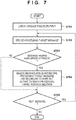
- the deletion processing unit 167 of the communication control unit 16 executes the processing shown in Fig. 7 .
- the deletion processing unit 167 performs deletion processing of a plurality of information notifications (messages) held in the processing waiting queue 168 by performing deletion processing based on the attributes of the information notifications (messages). That is, the deletion processing unit 167 performs deletion processing of the information notifications (messages) held in the processing waiting queue 168 so as to leave an information notification (message) representing the final state of control by the imaging control unit 15 of the first control application 13.
- the determination of a disconnection state includes the determination of a connection/non-connection state of a network itself and the determination of a connection/non-connection state depending on the activation state of an application.
- Fig. 3 shows a case in which when the communication state between the first and second control applications becomes a non-connection state, an information mismatch occurs between the first and second control applications.
- a disconnection 311 has occurred because of a network disconnection, an application trouble on the second control application 14 side, or the like in a state in which the first control application 13 and the second control application 14 are in a connection state (a state in which screen A is displaying an operation screen in a display state 301).
- the first control application 13 executes a first operation 321 on screen B in a display state 302, a second operation 322 on screen C in a display state 303, and a third operation 323 on screen D in a display state 304, the first control application 13 can transmit no information concerning each operation to the second control application 14 because of the disconnection state.
- the connection monitoring unit 161 determines a disconnection state and notifies the queue management unit 164 via the control unit 160 that no message queued in the processing waiting queue 168 can be processed. Based on this notification, the queue management unit 164 stops dequeue processing by the dequeue management unit 165. The dequeue management unit 165 stops operating the dequeue management unit to stop message communication. Note that because it is important to transmit no message, a connection state may be monitored by detecting an error upon transmitting a message in consideration of software design and implementation. Likewise, dequeuing may be stopped because of a message transmission error.
- GUI screen A provided by the second control application 14 is not updated. This causes a mismatch with the display state 304 on screen D on the GUI provided by the first control application 13. That is, when a connection state changes to a disconnection state, an information mismatch occurs between the first and second control applications.
- the deletion processing unit 167 performs deletion processing of the messages held in the processing waiting queue 168 so as to delete the messages, of the plurality of messages held in the processing waiting queue 168, which concern the first operation 321 on screen B and the second operation 322 on screen C shown in Fig. 3 and leave only the message concerning the third operation 323 on screen D.
- the deletion processing unit 167 performs deletion processing of information notifications (messages) held in the processing waiting queue 168 so as to leave an information notification representing the final state of control by the imaging control unit 15.
- the communication control unit 16 executes the following processing procedure while messages are retained.
- this processing procedure for example, while the dequeue management unit 165 of the communication control unit 16 stops dequeue processing, the deletion processing unit 167 of the communication control unit 16 executes processing at the occurrence of a next queue (first queue), in response to a start notification by a timer, or the like.
- step S701 in Fig. 7 the deletion processing unit 167 checks one of the messages held in the processing waiting queue 168 (queue holding unit) which is held (enqueued) in the processing waiting queue 168 first after the stoppage of dequeue processing.
- step S702 the deletion processing unit 167 decides a processing target message.
- messages are sequentially processed, starting from the message held (enqueued) first in the processing waiting queue 168 after the stoppage of dequeue processing.
- the first processing target is the oldest one of the messages held in the processing waiting queue 168, and newer messages are sequentially set as processing targets afterward.
- the deletion processing unit 167 determines whether a processing target message is a message having a high-order attribute.
- a high-order attribute corresponds to a message as a parent of a message subset constituted by a plurality of messages.
- a message subset includes a message as a parent (main message) and associated messages associated with the main message.
- main message main message
- the main message as the parent is a screen A 611.
- the main message as the parent is a screen B 621.
- the deletion processing unit 167 determines whether the processing target message is the parent (main message) of the subset. For example, as shown in Fig. 3 , when a screen transition has occurred from the display state 301 on screen A to the display state 302 on screen B on the GUI provided by the imaging control unit 15, the imaging control unit 15 notifies the message processing unit 162 of the communication control unit 16 of a message indicating a screen transition to screen B (for example, the message indicating the screen B 621 in Fig. 6 ). This message becomes a main message having a high-order attribute.
- step S703 determines in step S703 that the processing target message is not a message having a high-order attribute (main message) (NO in step S703), the process advances to step S705, in which the deletion processing unit 167 determines whether there is any next message held in the processing waiting queue 168.
- step S705 determines in step S705 that there is a next message (YES in step S705), the process returns to step S702 to repeat similar processing. If the deletion processing unit 167 determines in step S705 that the processing waiting queue 168 holds no next message (NO in step S705), this processing is terminated.
- step S703 Upon determining in step S703 that the processing target message is a message having a high-order attribute (main message) (YES in step S703), the deletion processing unit 167 advances the process to step S704.
- the deletion processing unit 167 specifies messages belonging to the same subset as that to which the message (main message) belongs from the messages held (enqueued) in the processing waiting queue 168 before the message currently set as a processing target, and deletes all the specified messages. For example, in the case shown in Fig. 6 , if the screen A 611 as a message having a high-order attribute (main message) is a processing target message, messages (associated messages) concerning operations 612 to 615 belonging to the same subset 61a as that to which the screen A 611 belongs become deletion targets.
- the deletion processing unit 167 specifies an information notification subset constituted by the information notification having the high-order attribute (main message) and information notifications (associated messages) associated with the information notification having the high-order attribute. The deletion processing unit 167 then performs deletion processing of the information notifications belonging to the subset of information notifications held (enqueued) in the processing waiting queue 168 before the processing target information notification.
- FIG. 4 shows a specific example of processing.
- a GUI screen 400 in Fig. 4 indicates a GUI screen transition provided by display control of the imaging control unit 15 in the first control application 13.
- An operation 401 indicates an operation procedure with respect to the GUI screen. Assume that when the operation 401 is executed, the first and second control applications are in a non-connection state.
- Step A1 to Step A3 respectively indicate A1 button to A3 button on screen A.
- Step A4 is the screen transition operation of switching from screen A to screen B.
- Step B1 and Step B2 respectively indicate a B1 button operation and a B2 text input operation on screen B.
- Step B3 is a screen transition operation of switching from screen B to screen C.
- Step C1 and Step C2 respectively indicate a C1 radio button operation and C2 checkbox operation on screen C.
- step S705 in Fig. 7 the message held (enqueued) first in the processing waiting queue 168 is processed as a processing target, and subsequent messages are sequentially processed. If there is a message next to the message currently processed as a processing target, subsequent processing is executed for the processing target message in step S702. If there is no next message, the processing is terminated.
- Fig. 6 exemplarily shows a message set constituted by a plurality of messages.
- the message having the high-order attribute indicates a screen transition to the screen A 611 ( Fig. 4 ).
- the message having the high-order attribute indicates a screen transition to the screen B 621 ( Fig. 4 ).
- the operation 401 in Fig. 4 is performed under the control of the imaging control unit 15.
- the message 402 notified in this case is held in the processing waiting queue 168.
- Fig. 5 exemplarily shows messages to be sequentially held in the processing waiting queue 168. If the operations 401 in Fig. 4 are sequentially performed, messages corresponding to the operations 501 to 503 (Step A1 to Step A3 in Fig. 4 ) in screen A are sequentially held (enqueued) in the processing waiting queue 168 (ST5A). Although the processing in each step in the flowchart of Fig. 7 is also performed during this period, because any message is not determined as a message having a high-order attribute (main message) in step S703, target messages are sequentially held in the processing waiting queue 168. Subsequently, when a message 504 indicating a screen transition from screen A to screen B (Step A4 in Fig.
- the deletion processing unit 167 specifies messages (associated messages (501 to 503)) belonging to the same subset 61a as that to which the message 504 (main message) belongs from the messages (501 to 503) held (enqueued) in the processing waiting queue 168, and deletes all the specified messages (associated messages (501 to 503)).
- the result obtained by executing the deletion processing becomes the state indicated by ST5C.
- the message indicating the screen transition from screen B to screen C is the message 507 having the high-order attribute (main message) in the subset 62b, and hence deletion processing in step S704 is performed in the processing shown in Fig. 7 .
- the deletion processing unit 167 specifies messages (associated messages (505 and 506)) belonging to the same subset 62b as that to which the message 507 (main message) belongs from the messages (504 to 506) held (enqueued) in the processing waiting queue 168 before the message 507 as a current processing target, and deletes all the specified messages (associated messages (505 and 506)).
- Step C1 and Step C2 in Fig. 4 Messages corresponding to operations 508 and 509 (Step C1 and Step C2 in Fig. 4 ) in screen C are sequentially held (enqueued) in the processing waiting queue 168 (ST5D).
- ST5D processing waiting queue 168
- target messages are sequentially held in the processing waiting queue 168. This result becomes the state indicted by ST5F.
- the messages corresponding to in-screen operations on screen A and screen B are deleted, and only the message corresponding to the screen transition is left in the processing waiting queue 168.
- a message set or subset is not limited to screen transitions or in-screen operations, and may be classifications having some kinds of meanings. For example, messages corresponding to operations between the start of an examination and the end of the examination may be grouped into a subset or messages corresponding to operations for one unit of imaging may be grouped into a subset.
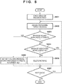
- Fig. 8 is a flowchart for explaining a procedure of processing in the communication control unit 16 of the first control application 13.
- the first embodiment has exemplified the arrangement configured to check one of the messages held in the processing waiting queue 168 (queue holding unit) which is held (enqueued) in the processing waiting queue 168 first after the stoppage of dequeue processing and set the checked message as a processing target.
- the second embodiment will exemplify an arrangement configured to check the message held (enqueued) in a processing waiting queue 168 lastly after the stoppage of dequeue processing and set the checked message as a processing target.
- a deletion processing unit 167 checks the message, of the messages held in the processing waiting queue 168 (queue holding unit), which is held (enqueued) in the processing waiting queue 168 lastly after the stoppage of dequeue processing.
- a set 601 of all messages indicates an example of classifying messages according to screen transitions and screen states.
- the set 601 of all the messages includes subsets 61a, 62b, and 63.
- the subset 61a includes a message concerning the display state of a screen A 611 and messages concerning operations 612 to 615 on screen A.
- the subset 62b includes a message concerning the display state of a screen B 621 and messages concerning operations 622 to 625 on screen B.
- the subset 62b includes a message concerning the display state of a subscreen 625 of screen B and operations 626 and 627 on the subscreen of screen B.
- the subset 63 includes messages 631 to 633 concerning information notifications 1, 2, and 3 as messages each having a high-order attribute.
- the current set (subset) of messages is the subset 63a having the display state of the screen A 611 as a high-order attribute.
- step S802 the deletion processing unit 167 decides a processing target message.
- the deletion processing unit 167 sequentially decides processing target messages, starting from the message held (enqueued) lastly in the processing waiting queue 168 after the stoppage of dequeue processing.
- the message decided as the first processing target is the newest one of the messages held in the processing waiting queue 168. Subsequently, the messages are sequentially decided as processing targets from newest to oldest.
- step S803 Processing in step S803 is the same as that in step S703. If the deletion processing unit 167 determines that the processing target is a message having a high-order attribute, the process advances to step S805.
- step S805 the deletion processing unit 167 sets a message subset having a high-order attribute as a current set as a processing target. That is, if the information notification (message) held in the processing waiting queue 168 lastly after determination of disconnection of communication is an information notification having a high-order attribute, the deletion processing unit 167 specifies an information notification set constituted by the information notification having the high-order attribute and information notifications (associated messages) associated with the information notification having the high-order attribute.
- the deletion processing unit 167 saves the information of the current set in a temporary memory for processing. In the subsequent processing, the deletion processing unit 167 can perform determination based on the comparison result obtained by comparing information in step S804. If, for example, a message having a high-order attribute is a message concerning the display state of the screen A 611, the information of the current set includes the message concerning the display state of the screen A 611 and messages concerning the operations 612 to 615 on screen A. This information is saved as the information of the current set in the temporary memory.
- step S803 Upon determining in step S803 that the processing target message is not a message having a high-order attribute, the deletion processing unit 167 advances the process to step S804.
- step S804 the deletion processing unit 167 determines whether the processing target message is an associated message of the current set (subset), that is, an associated message associated with a message having a high-order attribute (main message). If, for example, the main message indicates the display state of the screen A 611, the deletion processing unit 167 determines whether the processing target message is an associated message (a message concerning one of the operations 612 to 615 on screen A) subordinate to the main message. The deletion processing unit 167 compares the information of the current set with the information saved in the temporary memory. If the processing target message (current information) is not saved in the temporary memory, the deletion processing unit 167 determines that the processing target message is not an associated message of the current set (subset).
- main message indicates the display state of the screen A 611
- the deletion processing unit 167 determines whether the processing target message is an associated message (a message concerning one of the operations 612 to 615 on screen A) subordinate to the main message.
- the deletion processing unit 167 compares the information of the current set with the information saved
- step S804 If the processing target message is an associated message of the current set (subset) (YES in step S804), the process advances to step S807. In contrast, if the deletion processing unit 167 determines in step S804 that the processing target message is not an associated message of the current set (subset) (NO in step S804), the process advances to step S806. In step S806, the deletion processing unit 167 performs deletion processing of any information notification that is not included in the information notification set (current set). That is, the deletion processing unit 167 deletes any message that is not an associated message of the current set (subset), and the process advances to step S807.
- step S807 the deletion processing unit 167 determines whether there is a next message held in the processing waiting queue 168. If the deletion processing unit 167 determines in step S807 that there is a next message (YES in step S807), the process returns to step S802 to repeat similar processing. In contrast, if the deletion processing unit 167 determines in step S807 that there is no next message in the processing waiting queue 168 (NO in step S807), this processing is terminated.
- the first embodiment has exemplified the arrangement including the connection monitoring unit provided on the first control application 13 side.
- the embodiment is not limited to this arrangement.
- the connection monitoring unit can be provided on the second control application 14 side.
- a second control application 14 includes a connection monitoring unit that monitors a connection state with the first control application.
- the connection monitoring unit determines that the connection state is a disconnection state
- the GUI provided by the second control application 14 can display, as "UserUnkown", information indicating that no subject information can be obtained or notification information indicating a non-connection state.
- a control unit 142 can cause the GUI of a portable terminal 140 to perform display by performing display control of the GUI based on the monitoring result obtained by the connection monitoring unit on the second control application 14 side.
- notification it is possible to perform notification to stop communication concerning information (for example, a subset of messages corresponding to operations from the start of an examination to the end of the examination or a subset of messages corresponding to operations for one unit of imaging) communicated between the first and second control applications.
- information for example, a subset of messages corresponding to operations from the start of an examination to the end of the examination or a subset of messages corresponding to operations for one unit of imaging
- a deletion processing unit 167 can assign information notification (message) sets with priorities for setting a preferential order of processing and change the order of information notifications based on the assigned priorities.
- the deletion processing unit 167 can change the processing order of queues based on the priorities. For example, the deletion processing unit 167 can change the order so as to preferentially process message queues concerning patient information or, as in the subset 63, preferentially process independent notifications (messages 631 to 633 concerning information notifications 1, 2, and 3) having no associated message and respectively constituted by messages each having a high-order attribute.
- the present invention can solve disconnection problems in a network in a system in which two different applications simultaneously operate in cooperation with each other via a wireless or wired network, and even at the occurrence of disconnection, can notify information for restoring the states of the two applications to a latest state after reconnection.
- the present invention has the effect of improving responsiveness to improve the efficiency of restoration to the latest state.
- Embodiments) of the present invention can also be realized by a computer of a system or apparatus that reads out and executes computer executable instructions (e.g., one or more programs) recorded on a storage medium (which may also be referred to more fully as a 'non-transitory computer-readable storage medium') to perform the functions of one or more of the above-described embodiment(s) and/or that includes one or more circuits (e.g., application specific integrated circuit (ASIC)) for performing the functions of one or more of the above-described embodiment(s), and by a method performed by the computer of the system or apparatus by, for example, reading out and executing the computer executable instructions from the storage medium to perform the functions of one or more of the above-described embodiment(s) and/or controlling the one or more circuits to perform the functions of one or more of the above-described embodiment(s).
- ASIC application specific integrated circuit
- the computer may comprise one or more processors (e.g., central processing unit (CPU), micro processing unit (MPU)) and may include a network of separate computers or separate processors to read out and execute the computer executable instructions.
- the computer executable instructions may be provided to the computer, for example, from a network or the storage medium.
- the storage medium may include, for example, one or more of a hard disk, a random-access memory (RAM), a read only memory (ROM), a storage of distributed computing systems, an optical disk (such as a compact disc (CD), digital versatile disc (DVD), or Blu-ray Disc (BD)TM), a flash memory device, a memory card, and the like.
- a radiation imaging system that can control a radiation generating apparatus and a radiation detector based on communication between a first control application and a second control application, the system comprises: a connection monitoring unit configured to monitor a connection state of the communication; a holding unit configured to hold an information notification indicating a control state of an imaging control unit of the first control application that performs the control in a case where the connection monitoring unit determines that the connection state is a disconnection state; and a deletion processing unit configured to perform deletion processing of an information notification held in the holding unit so as to leave an information notification indicating a final state of control by the imaging control unit.
Landscapes
- Engineering & Computer Science (AREA)
- Health & Medical Sciences (AREA)
- Life Sciences & Earth Sciences (AREA)
- Medical Informatics (AREA)
- Biomedical Technology (AREA)
- General Health & Medical Sciences (AREA)
- Public Health (AREA)
- Physics & Mathematics (AREA)
- Radiology & Medical Imaging (AREA)
- Nuclear Medicine, Radiotherapy & Molecular Imaging (AREA)
- Animal Behavior & Ethology (AREA)
- Biophysics (AREA)
- Optics & Photonics (AREA)
- Heart & Thoracic Surgery (AREA)
- Molecular Biology (AREA)
- Surgery (AREA)
- High Energy & Nuclear Physics (AREA)
- Veterinary Medicine (AREA)
- Pathology (AREA)
- Computer Networks & Wireless Communication (AREA)
- Signal Processing (AREA)
- Primary Health Care (AREA)
- Epidemiology (AREA)
- General Business, Economics & Management (AREA)
- Business, Economics & Management (AREA)
- Software Systems (AREA)
- Theoretical Computer Science (AREA)
- Environmental & Geological Engineering (AREA)
- Computing Systems (AREA)
- Multimedia (AREA)
- General Engineering & Computer Science (AREA)
- General Physics & Mathematics (AREA)
- Human Computer Interaction (AREA)
- Apparatus For Radiation Diagnosis (AREA)
- Mobile Radio Communication Systems (AREA)
Abstract
Description
- The present invention relates to a radiation imaging system and a method of controlling the radiation imaging system and, more particularly, to a technique for causing an application for controlling radiation imaging and another application to operate in cooperation with each other.
- In recent years, the digitization of radiation imaging systems has led to the proliferation of systems designed to irradiate a radiation imaging apparatus with radiation from a radiation source through an object, make the radiation imaging apparatus generate a digital radiation image, and enable checking of the image immediately after imaging. In addition, advances in network link technology have enabled pieces of software in different apparatuses to operate in cooperation with each other.
- Japanese Patent No.
6195348 6195348 - The medical system disclosed in Japanese Patent No.
6195348 - Assume that in a system in which a plurality of applications cooperate to execute processing, applications are disconnected from each other. In this case, in order to resume a cooperative operation, it is necessary to solve an information mismatch caused between the two applications after the restoration of connection.
- The present invention provides a technique capable of solving an information mismatch caused between applications by performing deletion processing of held information notifications so as to leave an information notification representing the final state of control, in a system having a plurality of applications designed to execute processing in cooperation with each other, even when the applications are disconnected from each other and then reconnected again.
- The present invention in its first aspect provides a radiation imaging system as specified in
claims 1 to 14. - The present invention in its second aspect provides a method of controlling a radiation imaging system as specified in
claim 15. - The present invention can solve an information mismatch caused between applications by performing deletion processing of held information notifications so as to leave an information notification representing the final state of control.
- Further features of the present invention will become apparent from the following description of exemplary embodiments (with reference to the attached drawings).
-
-
Fig. 1 is a view showing an example of the arrangement of a radiation imaging system according to the first embodiment; -
Fig. 2 is a block diagram exemplarily showing the functional arrangement of the radiation imaging system; -
Fig. 3 is a view showing an example of the occurrence of an information mismatch caused by communication disconnection; -
Fig. 4 is a view showing a specific example of processing according to the first embodiment; -
Fig. 5 is a block diagram exemplarily showing messages sequentially held in a processing waiting queue; -
Fig. 6 is a block diagram exemplarily showing a message set constituted by a plurality of messages; -
Fig. 7 is a flowchart for explaining processing in a communication control unit according to the first embodiment; and -
Fig. 8 is a flowchart for explaining processing in a communication control unit according to the second embodiment. - Hereinafter, embodiments will be described in detail with reference to the attached drawings. Note, the following embodiments are not intended to limit the scope of the claimed invention. Multiple features are described in the embodiments, but limitation is not made an invention that requires all such features, and multiple such features may be combined as appropriate. Furthermore, in the attached drawings, the same reference numerals are given to the same or similar configurations, and redundant description thereof is omitted.
-
Fig. 1 shows an example of the arrangement of aradiation imaging system 10 according to the first embodiment. In many hospitals, mainly a radiation imaging technician (to be also referred to as an operator hereinafter) operates animaging control apparatus 150 while viewing the display device (monitor) on a console to make theimaging control apparatus 150 control aradiation generating apparatus 11 and aradiation detector 12, thus obtaining a radiation image. - A
first control application 13 is, for example, an application operating in theimaging control apparatus 150. Thefirst control application 13 performs display control to provide a GUI (graphical user interface) for the display device (monitor). The GUI displays information for assisting the operator to control the radiation imaging system for radiation imaging and information for assisting imaging, such as subject information. - For example, the
radiation imaging system 10 is configured to allow thefirst control application 13 to operate in cooperation with asecond control application 14 in another terminal (for example, a portable terminal 140). - The
second control application 14 is an application that can operate in theportable terminal 140 and other types of information devices and performs display control to provide the display unit of theportable terminal 140 with a GUI for presenting information to the operator. Information different from or identical to the contents displayed on the GUI provided by display control of thefirst control application 13 may be displayed/notified to the GUI of theportable terminal 140. Note that this system may include a plurality of portable terminals and can also use a wearable terminal as long as it can achieve the object of providing information to the operator. - A general procedure for an examination will be described next. First of all, the operator receives an order for radiation imaging via an in-hospital network. The imaging order is received in the
imaging control apparatus 150 and specifies subject information and the contents of imaging. In general, when an imaging order is delivered to the operator, a subject waits for imaging outside an examination room. The operator calls the subject into the examination room and prepares for an examination in accordance with the imaging order. Upon calling the subject into the examination room, the operator checks the name and birth date of the subject to prevent a mix-up between subjects. At this time, for example, the operator makes a check by matching the subject name on the imaging order received as subject information with the information displayed on the screen of theportable terminal 140. - Upon completing preparation for imaging, the operator adjusts the positions of the
radiation generating apparatus 11, the subject, and theradiation detector 12. The operator can change, for example, the order of imaging and the position of the subject at the time of imaging between, for example, a standing position and a supine position at the discretion of the operator depending on the state of the subject or the contents of the imaging order. - Subsequently, upon determining that radiation imaging can be performed, the operator inputs an instruction to start imaging to an operation unit (not shown). The
imaging control apparatus 150 controls theradiation generating apparatus 11 and theradiation detector 12 based on the operation of the operation unit to cause theradiation generating apparatus 11 to apply radiation and theradiation detector 12 to detect radiation transmitted through a subject. Theradiation detector 12 includes a pixel array in which a plurality of pixels for converting radiation into electrical signals are arranged in a matrix pattern, and can generate a radiation image corresponding to the converted electrical signals. - The
imaging control apparatus 150 is configured to be communicable with theradiation detector 12, and obtains the radiation image generated by theradiation detector 12 by communication. Theimaging control apparatus 150 performs display control to display the obtained radiation image on the display device (monitor). Upon checking the radiation image displayed on the monitor and finding no problem, the operator moves to the examination room to set a next imaging position, and performs imaging in the same procedure. If there is no need to perform next imaging, the examination is terminated, and the subject leaves the imaging room. - The functional arrangement of the radiation imaging system will be described next with reference to
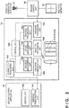
Fig. 2 . Theradiation imaging system 10 includes theradiation generating apparatus 11 that generates radiation, theradiation detector 12 that detects radiation, and the imaging control apparatus 150 (computer) that controls theradiation generating apparatus 11 and theradiation detector 12. Theradiation imaging system 10 can control theradiation generating apparatus 11 and theradiation detector 12 based on communication between the first control application and the second control application. Thefirst control application 13 is, for example, an application operating on the imaging control apparatus 150 (computer). Processing by each unit constituting thefirst control application 13 is implemented as a functional component of theimaging control apparatus 150. - The
second control application 14 may be an application operating on the same computer on which thefirst control application 13 operates or an application operating on a computer (for example, the portable terminal 140) different from the imaging control apparatus 150 (computer) on which thefirst control application 13 operates. In addition, thesecond control application 14 need not be a single application and may include a plurality of applications providing different GUIs. - The functional arrangement of the
first control application 13 will be described next. Thefirst control application 13 is constituted by animaging control unit 15 and acommunication control unit 16. Theimaging control unit 15 is the main logic unit of thefirst control application 13 which provides a GUI, controls display on the GUI, and executes imaging control in theradiation imaging system 10. Theimaging control unit 15 can operate singly and controls theradiation imaging system 10 while making theradiation generating apparatus 11 and theradiation detector 12 cooperate with each other. - The
communication control unit 16 is a DLL (Dynamic Link Library) that operates as a plugin of theimaging control unit 15. A plugin structure allows theimaging control unit 15 and thecommunication control unit 16 to operate in cooperation with each other as well as allowing theimaging control unit 15 to operate singly. The DLL need not always have a plugin structure, and theimaging control unit 15 and thecommunication control unit 16 may be configured to operate in cooperation with each other. This embodiment will be described on the premise that the DLL has a plugin structure. - The internal operation of the
communication control unit 16 will be described next. Acontrol unit 160 as a functional component of thecommunication control unit 16 controls the overall internal operation of thecommunication control unit 16. Amessage processing unit 162 performs reception processing of information from theimaging control unit 15 of thefirst control application 13. When information to be notified to thesecond control application 14 in accordance with the operation of theimaging control unit 15 is generated, theimaging control unit 15 notifies thecommunication control unit 16 of the information. In this case, information received from theimaging control unit 15 of thefirst control application 13 will be referred to as an information notification or message. In this case, information notifications include a notification concerning a screen transition of the GUI provided by thefirst control application 13 and a notification concerning the in-screen operation of the GUI. In addition, information notifications include a notification concerning the state of radiation imaging by theimaging control unit 15 of thefirst control application 13. - An
enqueue processing unit 163 holds (enqueues) the message received by themessage processing unit 162 in aprocessing waiting queue 168 under the control of thecontrol unit 160. Upon enqueuing the message, thecontrol unit 160 controls aqueue management unit 164 and adeletion processing unit 167 to manage the messages queued in theprocessing waiting queue 168. - A dequeue management unit 165 (obtaining unit) obtains (dequeues) a message held in the
processing waiting queue 168 under the control of thecontrol unit 160. Thedequeue management unit 165 obtains a message from theprocessing waiting queue 168 according to the FIFO (First In First Out) principle. Amessage communication unit 166 transmits the message obtained by the dequeue management unit 165 (obtaining unit) to amessage communication unit 141 of thesecond control application 14. - The
communication control unit 16 is connected to thesecond control application 14 via a wired or wireless network. Aconnection monitoring unit 161 that monitors the connection state of communication monitors the connection state of the network or the connection state originating from the operation state between applications. Thecontrol unit 160 controls the obtaining of an information notification (message) held in the processing waiting queue 168 (holding unit) based on the monitoring result obtained by theconnection monitoring unit 161. - If the
connection monitoring unit 161 determines a disconnection state, thecontrol unit 160 causes the dequeue management unit 165 (obtaining unit) to stop obtaining an information notification (message). Upon determining a state in which it is not possible to communicate with thesecond control application 14, that is, a disconnection state, theconnection monitoring unit 161 notifies thequeue management unit 164 via thecontrol unit 160 that no message queued in theprocessing waiting queue 168 can be processed. Upon being notified that no message can be processed, thequeue management unit 164 stops dequeue processing by thedequeue management unit 165. If theconnection monitoring unit 161 determines that the connection state is a disconnection state, theprocessing waiting queue 168 sequentially holds an information notification (message) indicating the control state of theimaging control unit 15 of thefirst control application 13. - In contrast, if the
connection monitoring unit 161 determines a reconnection state after determining a disconnection state, thecontrol unit 160 causes the dequeue management unit 165 (obtaining unit) to resume obtaining an information notification (message). That is, upon detecting a reconnection state while dequeue processing is stopped, theconnection monitoring unit 161 notifies thequeue management unit 164 via thecontrol unit 160 that queue processing can be performed. Upon being notified that queue processing can be performed, thequeue management unit 164 resumes dequeue processing by thedequeue management unit 165. - If the
connection monitoring unit 161 determines a reconnection state after determining a disconnection state, thecontrol unit 160 causes the dequeue management unit 165 (obtaining unit) to resume obtaining an information notification (message). Themessage communication unit 166 then obtains an information notification from theprocessing waiting queue 168 having undergone deletion processing by thedeletion processing unit 167, and transmits the notification to themessage communication unit 141 of thesecond control application 14. - A procedure of processing in the
communication control unit 16 will be described with reference to the flowchart ofFig. 7 andFigs. 3 to 6 . Thedeletion processing unit 167 of thecommunication control unit 16 executes the processing shown inFig. 7 . Thedeletion processing unit 167 performs deletion processing of a plurality of information notifications (messages) held in theprocessing waiting queue 168 by performing deletion processing based on the attributes of the information notifications (messages). That is, thedeletion processing unit 167 performs deletion processing of the information notifications (messages) held in theprocessing waiting queue 168 so as to leave an information notification (message) representing the final state of control by theimaging control unit 15 of thefirst control application 13. - Assume as preconditions that the
connection monitoring unit 161 has determined a disconnection state, and dequeue processing by thedequeue management unit 165 has stopped. Assume that in this case, the determination of a disconnection state includes the determination of a connection/non-connection state of a network itself and the determination of a connection/non-connection state depending on the activation state of an application. -
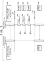
Fig. 3 shows a case in which when the communication state between the first and second control applications becomes a non-connection state, an information mismatch occurs between the first and second control applications. For example, as shown in the sequence chart ofFig. 3 , assume that a disconnection 311 has occurred because of a network disconnection, an application trouble on thesecond control application 14 side, or the like in a state in which thefirst control application 13 and thesecond control application 14 are in a connection state (a state in which screen A is displaying an operation screen in a display state 301). In this state, when thefirst control application 13 executes afirst operation 321 on screen B in adisplay state 302, asecond operation 322 on screen C in adisplay state 303, and athird operation 323 on screen D in adisplay state 304, thefirst control application 13 can transmit no information concerning each operation to thesecond control application 14 because of the disconnection state. - When no message can be transmitted between the first and second control applications, the
connection monitoring unit 161 determines a disconnection state and notifies thequeue management unit 164 via thecontrol unit 160 that no message queued in theprocessing waiting queue 168 can be processed. Based on this notification, thequeue management unit 164 stops dequeue processing by thedequeue management unit 165. Thedequeue management unit 165 stops operating the dequeue management unit to stop message communication. Note that because it is important to transmit no message, a connection state may be monitored by detecting an error upon transmitting a message in consideration of software design and implementation. Likewise, dequeuing may be stopped because of a message transmission error. - When the
imaging control unit 15 operates to generate an information notification while no message can be transmitted, messages to be transmitted to thesecond control application 14 are sequentially held and retained in theprocessing waiting queue 168. - That is, because no messages concerning the
first operation 321 on screen B, thesecond operation 322 on screen C, and thethird operation 323 on screen D can be transmitted, GUI screen A provided by thesecond control application 14 is not updated. This causes a mismatch with thedisplay state 304 on screen D on the GUI provided by thefirst control application 13. That is, when a connection state changes to a disconnection state, an information mismatch occurs between the first and second control applications. - In this embodiment, in order to prevent the occurrence of an information mismatch between the first and second control applications, the
deletion processing unit 167 performs deletion processing of the messages held in theprocessing waiting queue 168 so as to delete the messages, of the plurality of messages held in theprocessing waiting queue 168, which concern thefirst operation 321 on screen B and thesecond operation 322 on screen C shown inFig. 3 and leave only the message concerning thethird operation 323 on screen D. - The
deletion processing unit 167 performs deletion processing of information notifications (messages) held in theprocessing waiting queue 168 so as to leave an information notification representing the final state of control by theimaging control unit 15. - Leaving only the message concerning the
third operation 323 on screen D in theprocessing waiting queue 168 will transmit the message concerning thethird operation 323 on screen D left in theprocessing waiting queue 168 to thesecond control application 14 when the communication state between the first and second control applications becomes a connection state (reconnection 312). Thedisplay state 304 of screen D on the newest (latest) GUI provided by thefirst control application 13 matches GUI screen D provided by thesecond control application 14 to solve the information mismatch between the first and second control applications. - More specifically, the
communication control unit 16 executes the following processing procedure while messages are retained. In this processing procedure, for example, while thedequeue management unit 165 of thecommunication control unit 16 stops dequeue processing, thedeletion processing unit 167 of thecommunication control unit 16 executes processing at the occurrence of a next queue (first queue), in response to a start notification by a timer, or the like. - In step S701 in
Fig. 7 , thedeletion processing unit 167 checks one of the messages held in the processing waiting queue 168 (queue holding unit) which is held (enqueued) in theprocessing waiting queue 168 first after the stoppage of dequeue processing. - In step S702, the
deletion processing unit 167 decides a processing target message. In this embodiment, messages are sequentially processed, starting from the message held (enqueued) first in theprocessing waiting queue 168 after the stoppage of dequeue processing. The first processing target is the oldest one of the messages held in theprocessing waiting queue 168, and newer messages are sequentially set as processing targets afterward. - In step S703, the
deletion processing unit 167 determines whether a processing target message is a message having a high-order attribute. In this case, a high-order attribute corresponds to a message as a parent of a message subset constituted by a plurality of messages. A message subset includes a message as a parent (main message) and associated messages associated with the main message. For example, in the case shown inFig. 6 , in amessage subset 61a, the main message as the parent is ascreen A 611. In amessage subset 62b, the main message as the parent is ascreen B 621. - That is, in the processing in step S703, the
deletion processing unit 167 determines whether the processing target message is the parent (main message) of the subset. For example, as shown inFig. 3 , when a screen transition has occurred from thedisplay state 301 on screen A to thedisplay state 302 on screen B on the GUI provided by theimaging control unit 15, theimaging control unit 15 notifies themessage processing unit 162 of thecommunication control unit 16 of a message indicating a screen transition to screen B (for example, the message indicating thescreen B 621 inFig. 6 ). This message becomes a main message having a high-order attribute. If thedeletion processing unit 167 determines in step S703 that the processing target message is not a message having a high-order attribute (main message) (NO in step S703), the process advances to step S705, in which thedeletion processing unit 167 determines whether there is any next message held in theprocessing waiting queue 168. - If the
deletion processing unit 167 determines in step S705 that there is a next message (YES in step S705), the process returns to step S702 to repeat similar processing. If thedeletion processing unit 167 determines in step S705 that theprocessing waiting queue 168 holds no next message (NO in step S705), this processing is terminated. - Upon determining in step S703 that the processing target message is a message having a high-order attribute (main message) (YES in step S703), the
deletion processing unit 167 advances the process to step S704. - In step S704, the
deletion processing unit 167 specifies messages belonging to the same subset as that to which the message (main message) belongs from the messages held (enqueued) in theprocessing waiting queue 168 before the message currently set as a processing target, and deletes all the specified messages. For example, in the case shown inFig. 6 , if thescreen A 611 as a message having a high-order attribute (main message) is a processing target message, messages (associated messages) concerningoperations 612 to 615 belonging to thesame subset 61a as that to which thescreen A 611 belongs become deletion targets. - That is, if the processing target information notification (message) held first in the
processing waiting queue 168 after determination of a disconnection state is an information notification having a high-order attribute (main message), thedeletion processing unit 167 specifies an information notification subset constituted by the information notification having the high-order attribute (main message) and information notifications (associated messages) associated with the information notification having the high-order attribute. Thedeletion processing unit 167 then performs deletion processing of the information notifications belonging to the subset of information notifications held (enqueued) in theprocessing waiting queue 168 before the processing target information notification. -
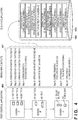
Fig. 4 shows a specific example of processing. AGUI screen 400 inFig. 4 indicates a GUI screen transition provided by display control of theimaging control unit 15 in thefirst control application 13. Anoperation 401 indicates an operation procedure with respect to the GUI screen. Assume that when theoperation 401 is executed, the first and second control applications are in a non-connection state. - In the
operation 401, Step A1 to Step A3 respectively indicate A1 button to A3 button on screen A. Step A4 is the screen transition operation of switching from screen A to screen B. Step B1 and Step B2 respectively indicate a B1 button operation and a B2 text input operation on screen B. Step B3 is a screen transition operation of switching from screen B to screen C. Step C1 and Step C2 respectively indicate a C1 radio button operation and C2 checkbox operation on screen C. - Assume that the
operation 401 is performed, and messages are held in theprocessing waiting queue 168 without performing deletion processing of messages. In this case,messages 402 are sequentially held in theprocessing waiting queue 168. - For example, in step S705 in
Fig. 7 , the message held (enqueued) first in theprocessing waiting queue 168 is processed as a processing target, and subsequent messages are sequentially processed. If there is a message next to the message currently processed as a processing target, subsequent processing is executed for the processing target message in step S702. If there is no next message, the processing is terminated. -
Fig. 6 exemplarily shows a message set constituted by a plurality of messages. In thesubset 61a, the message having the high-order attribute indicates a screen transition to the screen A 611 (Fig. 4 ). In theset 62b, the message having the high-order attribute indicates a screen transition to the screen B 621 (Fig. 4 ). Assume that theoperation 401 inFig. 4 is performed under the control of theimaging control unit 15. Themessage 402 notified in this case is held in theprocessing waiting queue 168. -
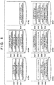
Fig. 5 exemplarily shows messages to be sequentially held in theprocessing waiting queue 168. If theoperations 401 inFig. 4 are sequentially performed, messages corresponding to theoperations 501 to 503 (Step A1 to Step A3 inFig. 4 ) in screen A are sequentially held (enqueued) in the processing waiting queue 168 (ST5A). Although the processing in each step in the flowchart ofFig. 7 is also performed during this period, because any message is not determined as a message having a high-order attribute (main message) in step S703, target messages are sequentially held in theprocessing waiting queue 168. Subsequently, when amessage 504 indicating a screen transition from screen A to screen B (Step A4 inFig. 4 ) is held (enqueued) in theprocessing waiting queue 168, the holding state of theprocessing waiting queue 168 becomes the state indicated by ST5B. In this case, the message indicating the screen transition from screen A to screen B is the message having the high-order attribute (main message) in thesubset 61a, and hence deletion processing in step S704 is performed in the processing shown inFig. 7 . In this case, thedeletion processing unit 167 specifies messages (associated messages (501 to 503)) belonging to thesame subset 61a as that to which the message 504 (main message) belongs from the messages (501 to 503) held (enqueued) in theprocessing waiting queue 168, and deletes all the specified messages (associated messages (501 to 503)). The result obtained by executing the deletion processing becomes the state indicated by ST5C. - Likewise, messages corresponding to
operations 505 and 506 (Step B1 and Step B2 inFig. 4 ) in screen B are sequentially held (enqueued) in the processing waiting queue 168 (ST5D). Although the processing in each step in the flowchart ofFig. 7 is also performed during this period, because any message is not determined as a message having a high-order attribute (main message) in step S703, target messages are sequentially held in theprocessing waiting queue 168. Subsequently, when amessage 507 indicating a screen transition from screen B to screen C (Step B3 inFig. 4 ) is held (enqueued) in theprocessing waiting queue 168, the holding state of theprocessing waiting queue 168 becomes the state indicated by ST5E. In this case, the message indicating the screen transition from screen B to screen C is themessage 507 having the high-order attribute (main message) in thesubset 62b, and hence deletion processing in step S704 is performed in the processing shown inFig. 7 . In this case, thedeletion processing unit 167 specifies messages (associated messages (505 and 506)) belonging to thesame subset 62b as that to which the message 507 (main message) belongs from the messages (504 to 506) held (enqueued) in theprocessing waiting queue 168 before themessage 507 as a current processing target, and deletes all the specified messages (associated messages (505 and 506)). - Messages corresponding to
operations 508 and 509 (Step C1 and Step C2 inFig. 4 ) in screen C are sequentially held (enqueued) in the processing waiting queue 168 (ST5D). Although the processing in each step in the flowchart ofFig. 7 is also performed during this period, because any message is not determined as a message having a high-order attribute (main message) in step S703, target messages are sequentially held in theprocessing waiting queue 168. This result becomes the state indicted by ST5F. The messages corresponding to in-screen operations on screen A and screen B are deleted, and only the message corresponding to the screen transition is left in theprocessing waiting queue 168. In addition, themessages processing waiting queue 168. With this operation, the message indicating the final state is held in theprocessing waiting queue 168. When connection is resumed between the first and second control applications, the message held in theprocessing waiting queue 168 and indicating the final state of control becomes a message as a transmission target to be transmitted to the second control application. Although this embodiment has exemplified a screen transition, a message set or subset is not limited to screen transitions or in-screen operations, and may be classifications having some kinds of meanings. For example, messages corresponding to operations between the start of an examination and the end of the examination may be grouped into a subset or messages corresponding to operations for one unit of imaging may be grouped into a subset. - The second embodiment will be described next. Differences between the first and second embodiments will be described below.
Fig. 8 is a flowchart for explaining a procedure of processing in thecommunication control unit 16 of thefirst control application 13. The first embodiment has exemplified the arrangement configured to check one of the messages held in the processing waiting queue 168 (queue holding unit) which is held (enqueued) in theprocessing waiting queue 168 first after the stoppage of dequeue processing and set the checked message as a processing target. The second embodiment will exemplify an arrangement configured to check the message held (enqueued) in aprocessing waiting queue 168 lastly after the stoppage of dequeue processing and set the checked message as a processing target. - In step S801, a
deletion processing unit 167 checks the message, of the messages held in the processing waiting queue 168 (queue holding unit), which is held (enqueued) in theprocessing waiting queue 168 lastly after the stoppage of dequeue processing. -
Fig. 6 shows an example of current information. Aset 601 of all messages indicates an example of classifying messages according to screen transitions and screen states. Theset 601 of all the messages includessubsets subset 61a includes a message concerning the display state of ascreen A 611 andmessages concerning operations 612 to 615 on screen A. Thesubset 62b includes a message concerning the display state of ascreen B 621 andmessages concerning operations 622 to 625 on screen B. Thesubset 62b includes a message concerning the display state of asubscreen 625 of screen B andoperations subset 63 includesmessages 631 to 633 concerninginformation notifications - If, for example, the message held (enqueued) lastly in the
processing waiting queue 168 is the message concerning theoperation 612 on screen A, the current set (subset) of messages is the subset 63a having the display state of thescreen A 611 as a high-order attribute. - In step S802, the
deletion processing unit 167 decides a processing target message. In this embodiment, thedeletion processing unit 167 sequentially decides processing target messages, starting from the message held (enqueued) lastly in theprocessing waiting queue 168 after the stoppage of dequeue processing. The message decided as the first processing target is the newest one of the messages held in theprocessing waiting queue 168. Subsequently, the messages are sequentially decided as processing targets from newest to oldest. - Processing in step S803 is the same as that in step S703. If the
deletion processing unit 167 determines that the processing target is a message having a high-order attribute, the process advances to step S805. - In step S805, the
deletion processing unit 167 sets a message subset having a high-order attribute as a current set as a processing target. That is, if the information notification (message) held in theprocessing waiting queue 168 lastly after determination of disconnection of communication is an information notification having a high-order attribute, thedeletion processing unit 167 specifies an information notification set constituted by the information notification having the high-order attribute and information notifications (associated messages) associated with the information notification having the high-order attribute. - The
deletion processing unit 167 saves the information of the current set in a temporary memory for processing. In the subsequent processing, thedeletion processing unit 167 can perform determination based on the comparison result obtained by comparing information in step S804. If, for example, a message having a high-order attribute is a message concerning the display state of thescreen A 611, the information of the current set includes the message concerning the display state of thescreen A 611 and messages concerning theoperations 612 to 615 on screen A. This information is saved as the information of the current set in the temporary memory. - Upon determining in step S803 that the processing target message is not a message having a high-order attribute, the
deletion processing unit 167 advances the process to step S804. - In step S804, the
deletion processing unit 167 determines whether the processing target message is an associated message of the current set (subset), that is, an associated message associated with a message having a high-order attribute (main message). If, for example, the main message indicates the display state of thescreen A 611, thedeletion processing unit 167 determines whether the processing target message is an associated message (a message concerning one of theoperations 612 to 615 on screen A) subordinate to the main message. Thedeletion processing unit 167 compares the information of the current set with the information saved in the temporary memory. If the processing target message (current information) is not saved in the temporary memory, thedeletion processing unit 167 determines that the processing target message is not an associated message of the current set (subset). - If the processing target message is an associated message of the current set (subset) (YES in step S804), the process advances to step S807. In contrast, if the
deletion processing unit 167 determines in step S804 that the processing target message is not an associated message of the current set (subset) (NO in step S804), the process advances to step S806. In step S806, thedeletion processing unit 167 performs deletion processing of any information notification that is not included in the information notification set (current set). That is, thedeletion processing unit 167 deletes any message that is not an associated message of the current set (subset), and the process advances to step S807. - In step S807, the
deletion processing unit 167 determines whether there is a next message held in theprocessing waiting queue 168. If thedeletion processing unit 167 determines in step S807 that there is a next message (YES in step S807), the process returns to step S802 to repeat similar processing. In contrast, if thedeletion processing unit 167 determines in step S807 that there is no next message in the processing waiting queue 168 (NO in step S807), this processing is terminated. - The third embodiment will be described next. The first embodiment has exemplified the arrangement including the connection monitoring unit provided on the
first control application 13 side. However, the embodiment is not limited to this arrangement. For example, the connection monitoring unit can be provided on thesecond control application 14 side. - A
second control application 14 includes a connection monitoring unit that monitors a connection state with the first control application. When the connection monitoring unit determines that the connection state is a disconnection state, the GUI provided by thesecond control application 14 can display, as "UserUnkown", information indicating that no subject information can be obtained or notification information indicating a non-connection state. For example, acontrol unit 142 can cause the GUI of aportable terminal 140 to perform display by performing display control of the GUI based on the monitoring result obtained by the connection monitoring unit on thesecond control application 14 side. Alternatively, it is possible to perform notification to stop communication concerning information (for example, a subset of messages corresponding to operations from the start of an examination to the end of the examination or a subset of messages corresponding to operations for one unit of imaging) communicated between the first and second control applications. - The fourth embodiment will be described next. This embodiment will exemplify an arrangement configured to set a priority for each message subset. A
deletion processing unit 167 can assign information notification (message) sets with priorities for setting a preferential order of processing and change the order of information notifications based on the assigned priorities. - For example, it is possible to assign
subsets set 601 of all messages with priorities for setting a preferential order of processing. Thedeletion processing unit 167 can change the processing order of queues based on the priorities. For example, thedeletion processing unit 167 can change the order so as to preferentially process message queues concerning patient information or, as in thesubset 63, preferentially process independent notifications (messages 631 to 633 concerninginformation notifications - According to each embodiment described above, in the system in which a plurality of applications execute processing in cooperation with each other, even when the connection between applications is disconnected first and then reconnected, it is possible to solve an information mismatch caused between the applications.
- The present invention can solve disconnection problems in a network in a system in which two different applications simultaneously operate in cooperation with each other via a wireless or wired network, and even at the occurrence of disconnection, can notify information for restoring the states of the two applications to a latest state after reconnection. In addition, the present invention has the effect of improving responsiveness to improve the efficiency of restoration to the latest state.
- Embodiments) of the present invention can also be realized by a computer of a system or apparatus that reads out and executes computer executable instructions (e.g., one or more programs) recorded on a storage medium (which may also be referred to more fully as a 'non-transitory computer-readable storage medium') to perform the functions of one or more of the above-described embodiment(s) and/or that includes one or more circuits (e.g., application specific integrated circuit (ASIC)) for performing the functions of one or more of the above-described embodiment(s), and by a method performed by the computer of the system or apparatus by, for example, reading out and executing the computer executable instructions from the storage medium to perform the functions of one or more of the above-described embodiment(s) and/or controlling the one or more circuits to perform the functions of one or more of the above-described embodiment(s). The computer may comprise one or more processors (e.g., central processing unit (CPU), micro processing unit (MPU)) and may include a network of separate computers or separate processors to read out and execute the computer executable instructions. The computer executable instructions may be provided to the computer, for example, from a network or the storage medium. The storage medium may include, for example, one or more of a hard disk, a random-access memory (RAM), a read only memory (ROM), a storage of distributed computing systems, an optical disk (such as a compact disc (CD), digital versatile disc (DVD), or Blu-ray Disc (BD)™), a flash memory device, a memory card, and the like.
- While the present invention has been described with reference to exemplary embodiments, it is to be understood that the invention is not limited to the disclosed exemplary embodiments. The scope of the following claims is to be accorded the broadest interpretation so as to encompass all such modifications and equivalent structures and functions.
- A radiation imaging system that can control a radiation generating apparatus and a radiation detector based on communication between a first control application and a second control application, the system comprises: a connection monitoring unit configured to monitor a connection state of the communication; a holding unit configured to hold an information notification indicating a control state of an imaging control unit of the first control application that performs the control in a case where the connection monitoring unit determines that the connection state is a disconnection state; and a deletion processing unit configured to perform deletion processing of an information notification held in the holding unit so as to leave an information notification indicating a final state of control by the imaging control unit.
Claims (15)
- A radiation imaging system that can control a radiation generating apparatus and a radiation detector based on communication between a first control application and a second control application, the system comprising:connection monitoring means for monitoring a connection state of the communication;holding means for holding an information notification indicating a control state of imaging control means of the first control application that performs the control in a case where the connection monitoring means determines that the connection state is a disconnection state; anddeletion processing means for performing deletion processing of an information notification held in the holding means so as to leave an information notification indicating a final state of control by the imaging control means.
- The system according to claim 1, wherein the deletion processing means specifies an information notification as a deletion target based on an attribute of the information notification.
- The system according to claim 1, further comprising:control means for controlling obtaining of the information notification held in the holding means based on a monitoring result obtained by the connection monitoring means;obtaining means obtaining the information notification held in the holding means; andcommunication means transmitting the information notification obtained by the obtaining means to the second control application,wherein the control means causes the obtaining means to stop obtaining the information notification in a case where the connection monitoring means determines a disconnection state.
- The system according to claim 2, wherein in a case where an information notification held in the holding means first after determination of the disconnection is an information notification having a high-order attribute, the deletion processing means specifies an information notification set constituted by including the information notification having the high-order attribute and an information notification associated with the information notification having the high-order attribute.
- The system according to claim 4, wherein the deletion processing means performs deletion processing of an information notification belonging to the set which is held in the holding means before a processing target information notification.
- The system according to claim 2, wherein when an information notification held in the holding means lastly after determination of the disconnection state is an information notification having a high-order attribute, the deletion processing means specifies an information notification set constituted by including the information notification having the high-order attribute and an information notification associated with the information notification having the high-order attribute.
- The system according to claim 6, wherein the deletion processing means performs deletion processing of an information notification that is not included in the specified information notification set.
- The system according to claim 1, wherein the information notification includes a notification concerning a screen transition of a GUI provided by the first control application.
- The system according to claim 8, wherein the information notification includes a notification concerning an in-screen operation of a GUI provided by the first control application.
- The system according to claim 1, wherein the information notification includes a notification concerning a state of radiation imaging by an imaging control means of the first control application.
- The system according to claim 1, wherein the second control application comprises connection monitoring means for monitoring a connection state of communication with the first control application,
wherein a GUI provided by the second control application is caused to display that subject information cannot be obtained in a case where the connection monitoring means determines that the connection state is a disconnection state. - The system according to claim 1, wherein the deletion processing means assigns the information notification set with a priority for setting a preferential order of processing, and changes an information notification order based on the assigned priority.
- The system according to claim 3, wherein the control means causes the obtaining means to resume obtaining the information notification in a case where the connection monitoring means determines that reconnection is made after determining a disconnection state.
- The system according to claim 13, wherein the communication means obtains the information notification from the holding means having undergone deletion processing by the deletion processing means and transmits the information notification to the second control application.
- A method of controlling a radiation imaging system that can control a radiation generating apparatus and a radiation detector based on communication between a first control application and a second control application, the method comprising:monitoring a connection state of the communication;holding an information notification indicating a control state of imaging control means of the first control application that performs the control in a case where it is determined in the monitoring that the connection state is a disconnection state; andperforming deletion processing of an information notification held in holding means so as to leave an information notification indicating a final state of control by the imaging control means.
Applications Claiming Priority (1)
| Application Number | Priority Date | Filing Date | Title |
|---|---|---|---|
| JP2019045137A JP7245083B2 (en) | 2019-03-12 | 2019-03-12 | Radiation imaging system and control method for radiation imaging system |
Publications (2)
| Publication Number | Publication Date |
|---|---|
| EP3708084A1 true EP3708084A1 (en) | 2020-09-16 |
| EP3708084B1 EP3708084B1 (en) | 2022-05-18 |
Family
ID=69810584
Family Applications (1)
| Application Number | Title | Priority Date | Filing Date |
|---|---|---|---|
| EP20160033.5A Active EP3708084B1 (en) | 2019-03-12 | 2020-02-28 | Radiation imaging system and method of controlling radiation imaging system |
Country Status (4)
| Country | Link |
|---|---|
| US (1) | US11330051B2 (en) |
| EP (1) | EP3708084B1 (en) |
| JP (1) | JP7245083B2 (en) |
| CN (1) | CN111685783B (en) |
Families Citing this family (2)
| Publication number | Priority date | Publication date | Assignee | Title |
|---|---|---|---|---|
| JP7245083B2 (en) * | 2019-03-12 | 2023-03-23 | キヤノン株式会社 | Radiation imaging system and control method for radiation imaging system |
| JP7313164B2 (en) | 2019-03-12 | 2023-07-24 | キヤノン株式会社 | Radiation imaging system and control method for radiation imaging system |
Citations (3)
| Publication number | Priority date | Publication date | Assignee | Title |
|---|---|---|---|---|
| US20170251989A1 (en) * | 2016-03-03 | 2017-09-07 | Canon Kabushiki Kaisha | X-ray imaging system, information processing method, and computer readable medium |
| JP6195348B2 (en) | 2013-04-18 | 2017-09-13 | 東芝メディカルシステムズ株式会社 | Medical system and medical device |
| US20180368797A1 (en) * | 2017-06-22 | 2018-12-27 | Konica Minolta, Inc. | Radiographic image capturing system |
Family Cites Families (10)
| Publication number | Priority date | Publication date | Assignee | Title |
|---|---|---|---|---|
| JP4328586B2 (en) * | 2003-09-02 | 2009-09-09 | キヤノン株式会社 | Radiation image connection processing method, radiation image connection processing apparatus, computer program, and computer-readable recording medium |
| JP5192708B2 (en) | 2007-03-27 | 2013-05-08 | パナソニック株式会社 | Terminal device for monitoring system |
| JP2010104581A (en) * | 2008-10-30 | 2010-05-13 | Canon Inc | X-ray photographing apparatus and method of radiography |
| JP5438424B2 (en) * | 2009-07-31 | 2014-03-12 | キヤノン株式会社 | Medical image photographing device and photographing method thereof |
| JP5850449B2 (en) | 2011-10-17 | 2016-02-03 | 国立研究開発法人放射線医学総合研究所 | Measurement information processing system and radiation measurement information processing system |
| US9037898B2 (en) | 2012-12-18 | 2015-05-19 | International Business Machines Corporation | Communication channel failover in a high performance computing (HPC) network |
| US10360267B2 (en) | 2015-06-10 | 2019-07-23 | Futurewei Technologies, Inc. | Query plan and operation-aware communication buffer management |
| EP3436993B1 (en) * | 2016-03-31 | 2023-07-05 | Koninklijke Philips N.V. | An imaging system and a communication platform for communication among a plurality of nodes of the imaging system |
| JP2019126655A (en) * | 2018-01-26 | 2019-08-01 | キヤノン株式会社 | Radiographic system, medical image capturing system, radiographic method, and program |
| JP7245083B2 (en) * | 2019-03-12 | 2023-03-23 | キヤノン株式会社 | Radiation imaging system and control method for radiation imaging system |
-
2019
- 2019-03-12 JP JP2019045137A patent/JP7245083B2/en active Active
-
2020
- 2020-02-28 EP EP20160033.5A patent/EP3708084B1/en active Active
- 2020-03-05 US US16/810,138 patent/US11330051B2/en active Active
- 2020-03-10 CN CN202010162902.0A patent/CN111685783B/en active Active
Patent Citations (3)
| Publication number | Priority date | Publication date | Assignee | Title |
|---|---|---|---|---|
| JP6195348B2 (en) | 2013-04-18 | 2017-09-13 | 東芝メディカルシステムズ株式会社 | Medical system and medical device |
| US20170251989A1 (en) * | 2016-03-03 | 2017-09-07 | Canon Kabushiki Kaisha | X-ray imaging system, information processing method, and computer readable medium |
| US20180368797A1 (en) * | 2017-06-22 | 2018-12-27 | Konica Minolta, Inc. | Radiographic image capturing system |
Also Published As
| Publication number | Publication date |
|---|---|
| CN111685783A (en) | 2020-09-22 |
| US20200296159A1 (en) | 2020-09-17 |
| US11330051B2 (en) | 2022-05-10 |
| CN111685783B (en) | 2023-10-13 |
| JP2020146168A (en) | 2020-09-17 |
| EP3708084B1 (en) | 2022-05-18 |
| JP7245083B2 (en) | 2023-03-23 |
Similar Documents
| Publication | Publication Date | Title |
|---|---|---|
| US11252342B2 (en) | Radiation imaging system and method of controlling radiation imaging system | |
| EP3708084B1 (en) | Radiation imaging system and method of controlling radiation imaging system | |
| US11223515B2 (en) | Cluster system, cluster system control method, server device, control method, and non-transitory computer-readable medium storing program | |
| US20230015800A1 (en) | A method, apparatus, medium and electronic device for configuring a gift list in a live broadcast room | |
| CN110120961A (en) | A kind of method of Distributed Services cluster and its route synchronization | |
| EP3282604A1 (en) | Integrated monitoring control device and integrated monitoring control system | |
| CN111510480B (en) | Request sending method and device and first server | |
| EP2784661A1 (en) | Computer program product, information processing method, and information processing apparatus | |
| WO2018221910A1 (en) | Method for calibration and apparatus therefor | |
| US20200288087A1 (en) | Information processing apparatus, information processing method, and storage medium | |
| CN114465963B (en) | Switch abnormity detection method and device, electronic equipment and computer readable medium | |
| CN113518183B (en) | Camera calling method and device and electronic equipment | |
| CN113010285B (en) | Method, device, device, medium and product for processing data | |
| US9003093B2 (en) | Connector apparatus and associated method for bridging data between data sources and data targets | |
| CN114745276B (en) | Switch bandwidth adjusting method and device, electronic equipment and computer readable medium | |
| CN117640709A (en) | Screen communication control method, device, equipment and computer storage medium | |
| US12182476B2 (en) | Voice notification system, voice notification method, and recording medium | |
| JP2008197885A (en) | Application abnormal end processing system method therefor and program | |
| US11301291B2 (en) | Information processing apparatus, management system, and control method thereof | |
| CN108495336A (en) | Data receiving-transmitting method, device based on wireless telecommunications and computer equipment | |
| CN117493024B (en) | Multi-process heterogeneous program migration method, storage medium and electronic equipment | |
| CN114691394A (en) | E-commerce data processing method, device and system | |
| US20260064293A1 (en) | Resource scheduling method, apparatus, medium, electronic device, and program product | |
| US20260119289A1 (en) | Server Support for Multiple Types of Embedded Datastores | |
| CN114070858A (en) | Data processing method and device, equipment and storage medium |
Legal Events
| Date | Code | Title | Description |
|---|---|---|---|
| PUAI | Public reference made under article 153(3) epc to a published international application that has entered the european phase |
Free format text: ORIGINAL CODE: 0009012 |
|
| STAA | Information on the status of an ep patent application or granted ep patent |
Free format text: STATUS: THE APPLICATION HAS BEEN PUBLISHED |
|
| AK | Designated contracting states |
Kind code of ref document: A1 Designated state(s): AL AT BE BG CH CY CZ DE DK EE ES FI FR GB GR HR HU IE IS IT LI LT LU LV MC MK MT NL NO PL PT RO RS SE SI SK SM TR |
|
| AX | Request for extension of the european patent |
Extension state: BA ME |
|
| STAA | Information on the status of an ep patent application or granted ep patent |
Free format text: STATUS: REQUEST FOR EXAMINATION WAS MADE |
|
| 17P | Request for examination filed |
Effective date: 20210322 |
|
| RBV | Designated contracting states (corrected) |
Designated state(s): AL AT BE BG CH CY CZ DE DK EE ES FI FR GB GR HR HU IE IS IT LI LT LU LV MC MK MT NL NO PL PT RO RS SE SI SK SM TR |
|
| GRAP | Despatch of communication of intention to grant a patent |
Free format text: ORIGINAL CODE: EPIDOSNIGR1 |
|
| RIC1 | Information provided on ipc code assigned before grant |
Ipc: G16H 40/67 20180101ALI20211028BHEP Ipc: G16H 40/63 20180101ALI20211028BHEP Ipc: G16H 30/20 20180101ALI20211028BHEP Ipc: G16H 40/60 20180101ALI20211028BHEP Ipc: A61B 6/00 20060101AFI20211028BHEP |
|
| STAA | Information on the status of an ep patent application or granted ep patent |
Free format text: STATUS: GRANT OF PATENT IS INTENDED |
|
| INTG | Intention to grant announced |
Effective date: 20211202 |
|
| GRAS | Grant fee paid |
Free format text: ORIGINAL CODE: EPIDOSNIGR3 |
|
| GRAA | (expected) grant |
Free format text: ORIGINAL CODE: 0009210 |
|
| STAA | Information on the status of an ep patent application or granted ep patent |
Free format text: STATUS: THE PATENT HAS BEEN GRANTED |
|
| AK | Designated contracting states |
Kind code of ref document: B1 Designated state(s): AL AT BE BG CH CY CZ DE DK EE ES FI FR GB GR HR HU IE IS IT LI LT LU LV MC MK MT NL NO PL PT RO RS SE SI SK SM TR |
|
| REG | Reference to a national code |
Ref country code: GB Ref legal event code: FG4D |
|
| REG | Reference to a national code |
Ref country code: CH Ref legal event code: EP |
|
| REG | Reference to a national code |
Ref country code: IE Ref legal event code: FG4D |
|
| REG | Reference to a national code |
Ref country code: DE Ref legal event code: R096 Ref document number: 602020003200 Country of ref document: DE |
|
| REG | Reference to a national code |
Ref country code: AT Ref legal event code: REF Ref document number: 1492697 Country of ref document: AT Kind code of ref document: T Effective date: 20220615 |
|
| REG | Reference to a national code |
Ref country code: LT Ref legal event code: MG9D |
|
| REG | Reference to a national code |
Ref country code: NL Ref legal event code: MP Effective date: 20220518 |
|
| REG | Reference to a national code |
Ref country code: AT Ref legal event code: MK05 Ref document number: 1492697 Country of ref document: AT Kind code of ref document: T Effective date: 20220518 |
|
| PG25 | Lapsed in a contracting state [announced via postgrant information from national office to epo] |
Ref country code: SE Free format text: LAPSE BECAUSE OF FAILURE TO SUBMIT A TRANSLATION OF THE DESCRIPTION OR TO PAY THE FEE WITHIN THE PRESCRIBED TIME-LIMIT Effective date: 20220518 Ref country code: PT Free format text: LAPSE BECAUSE OF FAILURE TO SUBMIT A TRANSLATION OF THE DESCRIPTION OR TO PAY THE FEE WITHIN THE PRESCRIBED TIME-LIMIT Effective date: 20220919 Ref country code: NO Free format text: LAPSE BECAUSE OF FAILURE TO SUBMIT A TRANSLATION OF THE DESCRIPTION OR TO PAY THE FEE WITHIN THE PRESCRIBED TIME-LIMIT Effective date: 20220818 Ref country code: NL Free format text: LAPSE BECAUSE OF FAILURE TO SUBMIT A TRANSLATION OF THE DESCRIPTION OR TO PAY THE FEE WITHIN THE PRESCRIBED TIME-LIMIT Effective date: 20220518 Ref country code: LT Free format text: LAPSE BECAUSE OF FAILURE TO SUBMIT A TRANSLATION OF THE DESCRIPTION OR TO PAY THE FEE WITHIN THE PRESCRIBED TIME-LIMIT Effective date: 20220518 Ref country code: HR Free format text: LAPSE BECAUSE OF FAILURE TO SUBMIT A TRANSLATION OF THE DESCRIPTION OR TO PAY THE FEE WITHIN THE PRESCRIBED TIME-LIMIT Effective date: 20220518 Ref country code: GR Free format text: LAPSE BECAUSE OF FAILURE TO SUBMIT A TRANSLATION OF THE DESCRIPTION OR TO PAY THE FEE WITHIN THE PRESCRIBED TIME-LIMIT Effective date: 20220819 Ref country code: FI Free format text: LAPSE BECAUSE OF FAILURE TO SUBMIT A TRANSLATION OF THE DESCRIPTION OR TO PAY THE FEE WITHIN THE PRESCRIBED TIME-LIMIT Effective date: 20220518 Ref country code: ES Free format text: LAPSE BECAUSE OF FAILURE TO SUBMIT A TRANSLATION OF THE DESCRIPTION OR TO PAY THE FEE WITHIN THE PRESCRIBED TIME-LIMIT Effective date: 20220518 Ref country code: BG Free format text: LAPSE BECAUSE OF FAILURE TO SUBMIT A TRANSLATION OF THE DESCRIPTION OR TO PAY THE FEE WITHIN THE PRESCRIBED TIME-LIMIT Effective date: 20220818 Ref country code: AT Free format text: LAPSE BECAUSE OF FAILURE TO SUBMIT A TRANSLATION OF THE DESCRIPTION OR TO PAY THE FEE WITHIN THE PRESCRIBED TIME-LIMIT Effective date: 20220518 |
|
| PG25 | Lapsed in a contracting state [announced via postgrant information from national office to epo] |
Ref country code: RS Free format text: LAPSE BECAUSE OF FAILURE TO SUBMIT A TRANSLATION OF THE DESCRIPTION OR TO PAY THE FEE WITHIN THE PRESCRIBED TIME-LIMIT Effective date: 20220518 Ref country code: PL Free format text: LAPSE BECAUSE OF FAILURE TO SUBMIT A TRANSLATION OF THE DESCRIPTION OR TO PAY THE FEE WITHIN THE PRESCRIBED TIME-LIMIT Effective date: 20220518 Ref country code: LV Free format text: LAPSE BECAUSE OF FAILURE TO SUBMIT A TRANSLATION OF THE DESCRIPTION OR TO PAY THE FEE WITHIN THE PRESCRIBED TIME-LIMIT Effective date: 20220518 Ref country code: IS Free format text: LAPSE BECAUSE OF FAILURE TO SUBMIT A TRANSLATION OF THE DESCRIPTION OR TO PAY THE FEE WITHIN THE PRESCRIBED TIME-LIMIT Effective date: 20220918 |
|
| PG25 | Lapsed in a contracting state [announced via postgrant information from national office to epo] |
Ref country code: SM Free format text: LAPSE BECAUSE OF FAILURE TO SUBMIT A TRANSLATION OF THE DESCRIPTION OR TO PAY THE FEE WITHIN THE PRESCRIBED TIME-LIMIT Effective date: 20220518 Ref country code: SK Free format text: LAPSE BECAUSE OF FAILURE TO SUBMIT A TRANSLATION OF THE DESCRIPTION OR TO PAY THE FEE WITHIN THE PRESCRIBED TIME-LIMIT Effective date: 20220518 Ref country code: RO Free format text: LAPSE BECAUSE OF FAILURE TO SUBMIT A TRANSLATION OF THE DESCRIPTION OR TO PAY THE FEE WITHIN THE PRESCRIBED TIME-LIMIT Effective date: 20220518 Ref country code: EE Free format text: LAPSE BECAUSE OF FAILURE TO SUBMIT A TRANSLATION OF THE DESCRIPTION OR TO PAY THE FEE WITHIN THE PRESCRIBED TIME-LIMIT Effective date: 20220518 Ref country code: DK Free format text: LAPSE BECAUSE OF FAILURE TO SUBMIT A TRANSLATION OF THE DESCRIPTION OR TO PAY THE FEE WITHIN THE PRESCRIBED TIME-LIMIT Effective date: 20220518 Ref country code: CZ Free format text: LAPSE BECAUSE OF FAILURE TO SUBMIT A TRANSLATION OF THE DESCRIPTION OR TO PAY THE FEE WITHIN THE PRESCRIBED TIME-LIMIT Effective date: 20220518 |
|
| REG | Reference to a national code |
Ref country code: DE Ref legal event code: R097 Ref document number: 602020003200 Country of ref document: DE |
|
| PLBE | No opposition filed within time limit |
Free format text: ORIGINAL CODE: 0009261 |
|
| STAA | Information on the status of an ep patent application or granted ep patent |
Free format text: STATUS: NO OPPOSITION FILED WITHIN TIME LIMIT |
|
| PG25 | Lapsed in a contracting state [announced via postgrant information from national office to epo] |
Ref country code: AL Free format text: LAPSE BECAUSE OF FAILURE TO SUBMIT A TRANSLATION OF THE DESCRIPTION OR TO PAY THE FEE WITHIN THE PRESCRIBED TIME-LIMIT Effective date: 20220518 |
|
| 26N | No opposition filed |
Effective date: 20230221 |
|
| PG25 | Lapsed in a contracting state [announced via postgrant information from national office to epo] |
Ref country code: SI Free format text: LAPSE BECAUSE OF FAILURE TO SUBMIT A TRANSLATION OF THE DESCRIPTION OR TO PAY THE FEE WITHIN THE PRESCRIBED TIME-LIMIT Effective date: 20220518 |
|
| PG25 | Lapsed in a contracting state [announced via postgrant information from national office to epo] |
Ref country code: MC Free format text: LAPSE BECAUSE OF FAILURE TO SUBMIT A TRANSLATION OF THE DESCRIPTION OR TO PAY THE FEE WITHIN THE PRESCRIBED TIME-LIMIT Effective date: 20220518 |
|
| REG | Reference to a national code |
Ref country code: CH Ref legal event code: PL |
|
| REG | Reference to a national code |
Ref country code: BE Ref legal event code: MM Effective date: 20230228 |
|
| PG25 | Lapsed in a contracting state [announced via postgrant information from national office to epo] |
Ref country code: LU Free format text: LAPSE BECAUSE OF NON-PAYMENT OF DUE FEES Effective date: 20230228 Ref country code: LI Free format text: LAPSE BECAUSE OF NON-PAYMENT OF DUE FEES Effective date: 20230228 Ref country code: CH Free format text: LAPSE BECAUSE OF NON-PAYMENT OF DUE FEES Effective date: 20230228 |
|
| REG | Reference to a national code |
Ref country code: IE Ref legal event code: MM4A |
|
| PG25 | Lapsed in a contracting state [announced via postgrant information from national office to epo] |
Ref country code: IT Free format text: LAPSE BECAUSE OF FAILURE TO SUBMIT A TRANSLATION OF THE DESCRIPTION OR TO PAY THE FEE WITHIN THE PRESCRIBED TIME-LIMIT Effective date: 20220518 Ref country code: IE Free format text: LAPSE BECAUSE OF NON-PAYMENT OF DUE FEES Effective date: 20230228 Ref country code: FR Free format text: LAPSE BECAUSE OF NON-PAYMENT OF DUE FEES Effective date: 20230228 |
|
| PG25 | Lapsed in a contracting state [announced via postgrant information from national office to epo] |
Ref country code: BE Free format text: LAPSE BECAUSE OF NON-PAYMENT OF DUE FEES Effective date: 20230228 |
|
| GBPC | Gb: european patent ceased through non-payment of renewal fee |
Effective date: 20240228 |
|
| PG25 | Lapsed in a contracting state [announced via postgrant information from national office to epo] |
Ref country code: BG Free format text: LAPSE BECAUSE OF FAILURE TO SUBMIT A TRANSLATION OF THE DESCRIPTION OR TO PAY THE FEE WITHIN THE PRESCRIBED TIME-LIMIT Effective date: 20220518 |
|
| PG25 | Lapsed in a contracting state [announced via postgrant information from national office to epo] |
Ref country code: BG Free format text: LAPSE BECAUSE OF FAILURE TO SUBMIT A TRANSLATION OF THE DESCRIPTION OR TO PAY THE FEE WITHIN THE PRESCRIBED TIME-LIMIT Effective date: 20220518 |
|
| PG25 | Lapsed in a contracting state [announced via postgrant information from national office to epo] |
Ref country code: GB Free format text: LAPSE BECAUSE OF NON-PAYMENT OF DUE FEES Effective date: 20240228 |
|
| PG25 | Lapsed in a contracting state [announced via postgrant information from national office to epo] |
Ref country code: GB Free format text: LAPSE BECAUSE OF NON-PAYMENT OF DUE FEES Effective date: 20240228 |
|
| PGFP | Annual fee paid to national office [announced via postgrant information from national office to epo] |
Ref country code: DE Payment date: 20250122 Year of fee payment: 6 |
|
| PG25 | Lapsed in a contracting state [announced via postgrant information from national office to epo] |
Ref country code: CY Free format text: LAPSE BECAUSE OF FAILURE TO SUBMIT A TRANSLATION OF THE DESCRIPTION OR TO PAY THE FEE WITHIN THE PRESCRIBED TIME-LIMIT; INVALID AB INITIO Effective date: 20200228 |
|
| PG25 | Lapsed in a contracting state [announced via postgrant information from national office to epo] |
Ref country code: HU Free format text: LAPSE BECAUSE OF FAILURE TO SUBMIT A TRANSLATION OF THE DESCRIPTION OR TO PAY THE FEE WITHIN THE PRESCRIBED TIME-LIMIT; INVALID AB INITIO Effective date: 20200228 |
|
| PG25 | Lapsed in a contracting state [announced via postgrant information from national office to epo] |
Ref country code: TR Free format text: LAPSE BECAUSE OF FAILURE TO SUBMIT A TRANSLATION OF THE DESCRIPTION OR TO PAY THE FEE WITHIN THE PRESCRIBED TIME-LIMIT Effective date: 20220518 |