EP3707462B1 - Tail portion - Google Patents
Tail portion Download PDFInfo
- Publication number
- EP3707462B1 EP3707462B1 EP18779821.0A EP18779821A EP3707462B1 EP 3707462 B1 EP3707462 B1 EP 3707462B1 EP 18779821 A EP18779821 A EP 18779821A EP 3707462 B1 EP3707462 B1 EP 3707462B1
- Authority
- EP
- European Patent Office
- Prior art keywords
- fins
- projectile
- tail portion
- fin
- bearing surface
- Prior art date
- Legal status (The legal status is an assumption and is not a legal conclusion. Google has not performed a legal analysis and makes no representation as to the accuracy of the status listed.)
- Active
Links
Images


Classifications
-
- F—MECHANICAL ENGINEERING; LIGHTING; HEATING; WEAPONS; BLASTING
- F42—AMMUNITION; BLASTING
- F42B—EXPLOSIVE CHARGES, e.g. FOR BLASTING, FIREWORKS, AMMUNITION
- F42B10/00—Means for influencing, e.g. improving, the aerodynamic properties of projectiles or missiles; Arrangements on projectiles or missiles for stabilising, steering, range-reducing, range-increasing or fall-retarding
- F42B10/02—Stabilising arrangements
- F42B10/14—Stabilising arrangements using fins spread or deployed after launch, e.g. after leaving the barrel
- F42B10/16—Wrap-around fins
-
- F—MECHANICAL ENGINEERING; LIGHTING; HEATING; WEAPONS; BLASTING
- F42—AMMUNITION; BLASTING
- F42B—EXPLOSIVE CHARGES, e.g. FOR BLASTING, FIREWORKS, AMMUNITION
- F42B10/00—Means for influencing, e.g. improving, the aerodynamic properties of projectiles or missiles; Arrangements on projectiles or missiles for stabilising, steering, range-reducing, range-increasing or fall-retarding
- F42B10/02—Stabilising arrangements
- F42B10/14—Stabilising arrangements using fins spread or deployed after launch, e.g. after leaving the barrel
-
- F—MECHANICAL ENGINEERING; LIGHTING; HEATING; WEAPONS; BLASTING
- F42—AMMUNITION; BLASTING
- F42B—EXPLOSIVE CHARGES, e.g. FOR BLASTING, FIREWORKS, AMMUNITION
- F42B10/00—Means for influencing, e.g. improving, the aerodynamic properties of projectiles or missiles; Arrangements on projectiles or missiles for stabilising, steering, range-reducing, range-increasing or fall-retarding
- F42B10/02—Stabilising arrangements
- F42B10/26—Stabilising arrangements using spin
Definitions
- the present invention relates to a tail portion for a fin-stabilized projectile, comprising at least two deployable fins, which are inclined.
- Fin stabilization is used, for example, for shells which are fired with smooth-bore barrels. Fin stabilization provides a stability in the projectile trajectory, and the stability increases somewhat if the projectile, moreover, is made to rotate about its longitudinal axis, for example by tilting of the fins. In certain applications, it is sufficient if only a part of the projectile, for example a rear portion comprising the fins, rotates, whilst the rest of the projectile does not rotate at all, or only rotates at a lower frequency. A rotation can also compensate for an uneven outer symmetry or an uneven weight distribution in the projectile. The rotation increases in relation to the degree of tilting of the fins.
- the rotation which provides a stabilization of the projectile trajectory can also be utilized to enable the projectile to make an effective scanning of the environment with the aid of, for example, proximity fuses, as are described in SE508652 .
- the rotation means that the proximity fuse scans the environment along a helical path which is defined partly by the projectile trajectory and partly by the rotation of the projectile, which has been superimposed on the projectile trajectory.
- SE508652 does not give any details of how the rotation is generated. By contrast, there are a host of documents regarding how fins are arrangeable in the tail portion of a projectile.
- the fins are generally arranged in a ring around the circumference of the projectile in its rear portion. They are either curved or flat in their deployed position. A typical example of symmetrically arranged, flat fins is shown in SE521445 .
- the characteristics of the fins and their effect on the projectile are determined to a large extent by their combined area. This area is limited, however, by the fact that it must be possible to arrange the fins in a stowed position during the firing, after which they assume their deployed position.
- the combined fin area is normally not greater than the circumference of the tail portion multiplied by the extent of the fins in the longitudinal direction, insofar as the fins are not mutually overlapped.
- Overlapping fins demand specific design measures, however, in order for them to be deployed without problems.
- the prior art therefore shows no examples of fins which are both inclined and overlapping. The tilting of the fins therefore has a limiting effect on the total fin area.
- Document US 4203569 A discloses a fin and nozzle unit for a free-flight rocket.
- the described device comprises a cylindrical nozzle body that has an opening for releasing a stream of gas.
- the unit also comprises a set of fins that can move between a retracted launch position and an extended flight position.
- the fins have curved or angled parts that are in the path of the gas stream during launch, which creates a spinning motion for the rocket. Once the rocket is in flight, the fins move out of the gas stream to avoid further spin.
- the fins are aerodynamically neutral when extended and have detent elements that hold them in place.
- the detent elements also keep additional fin members of the wrap-around type in their launch position until the first set of fins moves into flight position, whereupon the additional fins are released and moved into their extended position by spring action.
- Document US 6978967 B1 concerns a Space saving fin deployment system for munitions and missiles.
- the system concerns deployment of straight flat fins for roll control of missiles and munitions.
- the system comprises a wrap-around fin concept, where the fins are arranged in a wrapped configuration around a boomtail structure, generating space-saving within the projectile body.
- the fins may be made of elastic material, eliminating the need for mechanical means of deployment and springs. This system creates space savings, allowing for increased electronic packaging or lethality, while also providing roll control during flight by enabling a straight fin deployment.
- the aim is therefore to provide a maximization of the total fin area, at the same time as possibilities for other design measures, such as tilting of the fins, are retained.
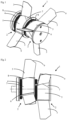
- Fig 1 a tail portion 1 according to the invention for a projectile, such as a shell or the like.
- the projectile in its entirety is not shown, but only the tail portion which is the subject of the invention.
- the other parts of the projectile can be configured according to any design which is known to the person skilled in the art.
- the tail portion 1 is divided into at least two sections 2, which are arranged adjacent to one another in the longitudinal direction of the tail portion 1 and of the projectile.
- the sections 2 are arranged one after the other, viewed in the notional direction of movement of the projectile.
- Each section 2 has in the preferred embodiment three fins 3, but other embodiments, having different numbers of fins 3, are obviously accommodated within the scope of the inventive concept.
- the fins 3 have a deployed position, which is shown in Fig 1 , but also a stowed position, in which they are clamped against bearing surfaces 5.
- the stowed position is appropriate during storage, transport and loading of the projectile, before it is fired.
- the fins 3 are held in place in the stowed position with the aid of an overlying, cylindrical sleeve, or hood, (not shown), which is put in place during the production of the projectile.
- the sleeve is removed and the fins 3 assume their deployed position.
- Each section 2 also has a linking member in the form of a manoeuvring ring 4, which functionally links together the fins 3 in the section 2.
- the linking members 4 of the different sections 2 are independent of one another.
- the appearance and exact design of the fins 3 are variable within the scope of what the person skilled in the art is familiar with and deems appropriate.
- the maximum extent of the fins 3 from the centre of the projectile is of importance for the characteristics of the projectile.
- the fins 3 are inclined at an angle in relation to the longitudinal direction of the projectile.
- Each fin 3 extends in the stowed position as far as possible along a bearing surface 5, up to the next fin 3 in the circumferential direction, without overlapping this.
- the bearing surfaces 5 have an area which corresponds to the area of the respective fin 3.
- the size of the fins 3 is limited by the size of the bearing surfaces 5, and, for a maximization of the fin area 3, the fin area corresponds to the area of the whole of the bearing surface 5.
- the front edges of the fins 3, in the notional direction of movement, are in one embodiment bevelled in order to reduce the air resistance of the projectile.
- Each bearing surface 5 should therefore be as large as possible.
- each bearing surface 5 In order to make room for as large a bearing surface 5 as possible within a notional, cylindrical outer surface, which is defined by the maximum radius of the projectile and which is corresponded to by the overlying cylindrical sleeve prior to the firing of the projectile, each bearing surface 5 is convex and extends inside the space within the notional, cylindrical outer surface. The area of the bearing surface 5 is then greater than if the bearing surface were arranged along the notional, cylindrical, encompassing surface. Since two or more sections 2 are arranged one after the other on the tail portion 1, the total fin area is greater than if only one section 2 with fins 3 were arranged on the tail portion 1.
- each shaft 6, about which each fin 3 is pivotable is arranged in or substantially parallel with the bearing surface 5.
- the shaft 6 slopes in relation to the longitudinal direction of the projectile, as can be seen especially well in Fig 2 , so that the desired tilting of the fins 3 is achieved.
- the shaft 6, in the preferred embodiment is, however, substantially parallel with the notional, cylindrical outer surface.
- the curvature of the bearing surface 5 is also such that it gradually nears the notional, cylindrical, encompassing surface, in the direction away from the shaft 6. At the far end of the bearing surface 5, viewed from the associated rotation shaft 6, the bearing surface 5 reaches up to the notional encompassing surface and merges there into a cylindrical portion 7.
- a truncated corner portion 9 in the corresponding region.
- the truncated corner portion 9, in the shown embodiment is a compromise between a large fin area and the possibility of keeping the fin 3 clamped against the projectile body during the firing.
- the fins 3 are produced of an elastic material, so that they quickly resume their original, deployed shape when the overlying sleeve is removed upon the firing of the projectile.
- the manoeuvring ring 4 links the fins 3 in one and the same section 2.
- the encompassing sleeve is pulled off from a section, upon the firing of the projectile at least one of the fins 3 will be deployed due to the elasticity in the material. This leads to a rotation of the fin 3 about the shaft 6, and the manoeuvring ring 4 will be rotated a short way, since each shaft 6, in the preferred embodiment, is provided with a small gearwheel 8 on its end.
- the gearwheel 8 engages with the manoeuvring ring 4, which is geared, and the rotary motion of the shaft 6 is in this way transmitted to the manoeuvring ring 4.
- the manoeuvring ring 4 in turn transmits its rotary motion to the other shafts 6, the fins 3 of which have probably also started a deployment.
- the deployment will take place synchronously, wherein a fin 3, which has a somewhat greater deployment tendency speeds up the other fins 3, and a fin 3 with somewhat later deployment slows the process a little.
- the synchronization of the deployment also means that the stabilization of the projectile is controlled and predictable.
- the tail portion 1 is shown from its rear end.
- the fins 3, which are also shown in Fig 1 and 2 are evenly distributed over the circumference of the tail portion 1 in the preferred embodiment. This is a result of that placement of the fin shafts 6 which has been chosen in the preferred embodiment.
- a person skilled in the art in this field can after routine tests choose other placements of the fin shafts 6 if it provides other desired characteristics of the projectile when this is in a trajectory on the way towards a target.
- Fig 4a and 4b show in a sectional view two different variants of the tail portion 1.
- the variant in Fig 4a is a free-spinning tail portion 1, in which an outer part 11 of the tail portion 1 is rotatably arranged on an inner shaft 12, and is hence arranged rotatably in relation to the rest of the projectile.
- the rotatability of the outer part 11 in relation to the inner shaft 12 is preferably achieved with the aid of ball bearings 10, even though other means which are known to the person skilled in the art are conceivable.
- Fig 4b is shown a fixed tail portion. To use both fixed and free-spinning tail portions 1 is per se previously known to the person skilled in the art.
- the tail portion 1 according to the invention has substantially the same configuration in other parts, regardless of whether it is arranged in a fixed or free-spinning manner.
- Figures 5a-5c illustrate how the bearing surfaces 5 are configured.
- the tail portion 1 is shown in a simplified form, in which both the fins 3, their shafts 6, and the manoeuvring rings 4 on the two sections 2 have been removed in order that the bearing surfaces 5 shall be seen as clearly as possible.
- both the upper and the lower bearing surfaces 5 are located at a distance from the cylindrical outer contour.
- the distance between the respective bearing surface 5 and the outer contour gradually diminishes.
- the bearing surface 5 reaches the outer contour, it merges into the cylindrical surface portion 7.
- each bearing surface 5 slopes inwards, away from the cylindrical outer contour, so that its area is as large as possible.
- Each bearing surface 5 coincides with a part of an envelope surface of a notional cone.
- the notional cone 13 is, however, different for the different bearing surfaces 5.
- Fig 5b is shown such a cone 13, which can illustrate how each bearing surface 5 has been given its shape.
- the apex 14 of the notional cone 13 is displaced in the lateral direction in relation to the centre of the tail portion 1. This has the result that the envelope surface of the cone 13 is arranged asymmetrically both in relation to the centre of the tail portion 1 and in relation to the cylindrical outer contour.
- the centre line of the cone 13 can be parallel with the centre line of the projectile, but in many embodiments forms an angle thereto.
- Each bearing surface 5 coincides with an own notional cone 13, both the bearing surfaces 5 which lie in the same section 2 and the bearing surfaces 5 which are located in different sections 2.
- six different cones 13 have been calculated in support of the configuration of the six different bearing surfaces 5.
- I Figures 5b and 5c for the sake of clarity, only one of these cones 13 is shown. With the aid of computer-aided production technology, the tail portion 1 according to Fig. 5a will be able to be produced.
- the proposed solution has a number of advantages in relation to existing technology comprising fins arranged in only one section.
- technical solutions in which a very small space is available to achieve a sufficient total fin area are enabled.
- the maximum extent of the fins 3 from the centre of the projectile, the span, is increased, at the same time as the total fin area is maintained.
- the time it takes to spin up the projectile to the correct rotation speed is reduced, moreover, by at least 50% in relation to solutions comprising a single fin section, and the stability margin increases.
- the size and shape of the fins 3 are affected by the configuration of the bearing surfaces 5, which in turn is determined by the size of the notional cone 13 and its displacement and angle in relation to the centre line of the tail portion 1. A number of different appearances of the bearing surfaces 5 are therefore possible to achieve within the scope of these principles, even though not all variants are shown in the figures.
- the shape and size of the fins 3 are variable in dependence on the projectile characteristics which are sought, but are naturally limited by the shape and size of the bearing surfaces 5.
- the placement of the fin shafts 6 in the circumferential direction of the tail portion is also variable in many different ways.
- a placement in which the fin shafts 6 are evenly scattered over the circumference of the tail portion 1 has been shown.
- An example of fin placement is that the fins 3 and the fin shafts 6 are placed symmetrically in the circumferential direction within their section 2, but that the fins 3 in the different sections are displaced only a short way, so that groups comprising fins 3 from different sections 2 are produced.
- the separation angle is 120° between the three fins in each section or segment.
- the two rows must be asymmetrically displaced in relation to one another so that the separation angle is not 60° between two fins, but rather 70° and 50°, for example, for the respective pair. In this way, a very good result has been attained for certain applications.
- Another way of achieving a grouping of the fins 3 is to make the fins 3 form the groups section by section.
- a further variation option for achieving other embodiments is that certain sections 2 are provided with a greater number of fins 3, whilst other sections 2 have fewer.
- the size of the fins 3 is also mutually variable, for example by virtue of the fact that the fins 3 in one section 2 are consistently larger than in another section 2.
- the cylindrical sleeve which covers the fins 3 when they are clamped against the bearing surfaces 5, can be a separate component in certain embodiments, but can also be produced as a part of the cartridge case.
- the cartridge case covers a greater or lesser part of the projectile and contains the propellant charge and the ignition agent.
- the cartridge case will be separated from the projectile during a certain stage of the firing, and the fins 3 will in principle at the same time be laid bare and can be deployed as soon as the projectile has left the barrel.
Landscapes
- Physics & Mathematics (AREA)
- Fluid Mechanics (AREA)
- Engineering & Computer Science (AREA)
- General Engineering & Computer Science (AREA)
- Powder Metallurgy (AREA)
- Toys (AREA)
- Aiming, Guidance, Guns With A Light Source, Armor, Camouflage, And Targets (AREA)
- Lining And Supports For Tunnels (AREA)
- Polishing Bodies And Polishing Tools (AREA)
- Structures Of Non-Positive Displacement Pumps (AREA)
Description
- The present invention relates to a tail portion for a fin-stabilized projectile, comprising at least two deployable fins, which are inclined.
- Amongst the many types of projectiles which are used in various military connections are found fin-stabilized projectiles as an important sub-group of projectiles. Fin stabilization is used, for example, for shells which are fired with smooth-bore barrels. Fin stabilization provides a stability in the projectile trajectory, and the stability increases somewhat if the projectile, moreover, is made to rotate about its longitudinal axis, for example by tilting of the fins. In certain applications, it is sufficient if only a part of the projectile, for example a rear portion comprising the fins, rotates, whilst the rest of the projectile does not rotate at all, or only rotates at a lower frequency. A rotation can also compensate for an uneven outer symmetry or an uneven weight distribution in the projectile. The rotation increases in relation to the degree of tilting of the fins.
- The rotation which provides a stabilization of the projectile trajectory can also be utilized to enable the projectile to make an effective scanning of the environment with the aid of, for example, proximity fuses, as are described in
SE508652 -
SE508652 - The fins are generally arranged in a ring around the circumference of the projectile in its rear portion. They are either curved or flat in their deployed position. A typical example of symmetrically arranged, flat fins is shown in
SE521445 - The characteristics of the fins and their effect on the projectile are determined to a large extent by their combined area. This area is limited, however, by the fact that it must be possible to arrange the fins in a stowed position during the firing, after which they assume their deployed position. The combined fin area is normally not greater than the circumference of the tail portion multiplied by the extent of the fins in the longitudinal direction, insofar as the fins are not mutually overlapped. Overlapping fins demand specific design measures, however, in order for them to be deployed without problems. The prior art therefore shows no examples of fins which are both inclined and overlapping. The tilting of the fins therefore has a limiting effect on the total fin area.
- Document
US 4203569 A discloses a fin and nozzle unit for a free-flight rocket. The described device comprises a cylindrical nozzle body that has an opening for releasing a stream of gas. The unit also comprises a set of fins that can move between a retracted launch position and an extended flight position. The fins have curved or angled parts that are in the path of the gas stream during launch, which creates a spinning motion for the rocket. Once the rocket is in flight, the fins move out of the gas stream to avoid further spin. The fins are aerodynamically neutral when extended and have detent elements that hold them in place. The detent elements also keep additional fin members of the wrap-around type in their launch position until the first set of fins moves into flight position, whereupon the additional fins are released and moved into their extended position by spring action. - Document
US 6978967 B1 concerns a Space saving fin deployment system for munitions and missiles. The system concerns deployment of straight flat fins for roll control of missiles and munitions. The system comprises a wrap-around fin concept, where the fins are arranged in a wrapped configuration around a boomtail structure, generating space-saving within the projectile body. The fins may be made of elastic material, eliminating the need for mechanical means of deployment and springs. This system creates space savings, allowing for increased electronic packaging or lethality, while also providing roll control during flight by enabling a straight fin deployment. - The aim is therefore to provide a maximization of the total fin area, at the same time as possibilities for other design measures, such as tilting of the fins, are retained.
- The objective on which the invention is based is achieved if the tail portion indicated in the introduction is characterized as in
patent claim 1. - Further advantages are attained if the invention, moreover, is given one or more of the characteristics according to one or more of the subordinate patent claims.
- The invention will now be described with reference to appended drawings, in which:
- Fig 1
- shows a perspective view of an embodiment of a tail portion according to the invention;
- Fig 2
- shows a direct side view of the tail portion according to
Fig 1 ; - Fig 3
- shows an end view of the tail portion according to
Fig 1 ; - Fig 4a
- shows a sectional view of the tail portion according to
Fig 1 ; - Fig 4b
- shows a sectional view of another embodiment of the tail portion;
- Fig 5a
- shows a schematic perspective view of a tail portion according to the invention, in which, inter alia, the fins have been omitted;
- Fig 5b
- shows a first basic diagram, which illustrates the configuration of bearing surfaces forming part of the tail portion according to the invention; and
- Fig 5c
- shows a second basic diagram, which illustrates the configuration of the bearing surfaces.
- In
Fig 1 is shown atail portion 1 according to the invention for a projectile, such as a shell or the like. The projectile in its entirety is not shown, but only the tail portion which is the subject of the invention. The other parts of the projectile can be configured according to any design which is known to the person skilled in the art. - The
tail portion 1 is divided into at least twosections 2, which are arranged adjacent to one another in the longitudinal direction of thetail portion 1 and of the projectile. In other words, thesections 2 are arranged one after the other, viewed in the notional direction of movement of the projectile. - Each
section 2 has in the preferred embodiment threefins 3, but other embodiments, having different numbers offins 3, are obviously accommodated within the scope of the inventive concept. Thefins 3 have a deployed position, which is shown inFig 1 , but also a stowed position, in which they are clamped against bearingsurfaces 5. The stowed position is appropriate during storage, transport and loading of the projectile, before it is fired. In the preferred embodiment, thefins 3 are held in place in the stowed position with the aid of an overlying, cylindrical sleeve, or hood, (not shown), which is put in place during the production of the projectile. In conjunction with the firing, the sleeve is removed and thefins 3 assume their deployed position. - Each
section 2 also has a linking member in the form of amanoeuvring ring 4, which functionally links together thefins 3 in thesection 2. The linkingmembers 4 of thedifferent sections 2 are independent of one another. - The appearance and exact design of the
fins 3 are variable within the scope of what the person skilled in the art is familiar with and deems appropriate. In addition to the size of the fin area, the maximum extent of thefins 3 from the centre of the projectile is of importance for the characteristics of the projectile. In the embodiment shown inFig 1 , thefins 3 are inclined at an angle in relation to the longitudinal direction of the projectile. Eachfin 3 extends in the stowed position as far as possible along a bearingsurface 5, up to thenext fin 3 in the circumferential direction, without overlapping this. The bearing surfaces 5 have an area which corresponds to the area of therespective fin 3. The size of thefins 3 is limited by the size of the bearing surfaces 5, and, for a maximization of thefin area 3, the fin area corresponds to the area of the whole of the bearingsurface 5. The front edges of thefins 3, in the notional direction of movement, are in one embodiment bevelled in order to reduce the air resistance of the projectile. - Each bearing
surface 5 should therefore be as large as possible. In order to make room for as large abearing surface 5 as possible within a notional, cylindrical outer surface, which is defined by the maximum radius of the projectile and which is corresponded to by the overlying cylindrical sleeve prior to the firing of the projectile, each bearingsurface 5 is convex and extends inside the space within the notional, cylindrical outer surface. The area of the bearingsurface 5 is then greater than if the bearing surface were arranged along the notional, cylindrical, encompassing surface. Since two ormore sections 2 are arranged one after the other on thetail portion 1, the total fin area is greater than if only onesection 2 withfins 3 were arranged on thetail portion 1. As a result of the arrangement of two ormore sections 2 one after the other, instead of a single section, it is also optionally achieved that the maximum extent of thefins 3 from the centre of the projectile increases, whilst the total fin area is kept constant, which gives the person skilled in the art further chance to work on the characteristics of the projectile. - The curvature of the bearing
surface 5 is such that eachshaft 6, about which eachfin 3 is pivotable, is arranged in or substantially parallel with the bearingsurface 5. Theshaft 6 slopes in relation to the longitudinal direction of the projectile, as can be seen especially well inFig 2 , so that the desired tilting of thefins 3 is achieved. At the same time, theshaft 6, in the preferred embodiment, is, however, substantially parallel with the notional, cylindrical outer surface. The curvature of the bearingsurface 5 will be described in further detail with reference toFig 5a-c . - The curvature of the bearing
surface 5 is also such that it gradually nears the notional, cylindrical, encompassing surface, in the direction away from theshaft 6. At the far end of the bearingsurface 5, viewed from the associatedrotation shaft 6, the bearingsurface 5 reaches up to the notional encompassing surface and merges there into acylindrical portion 7. In order to avoid an overly severe bending of thefin 3 when it is clamped against the bearingsurface 5, it has in the preferred embodiment atruncated corner portion 9 in the corresponding region. Even though it is desirable that thefin 3, in the deployed state, has as large an extent as possible, thetruncated corner portion 9, in the shown embodiment, is a compromise between a large fin area and the possibility of keeping thefin 3 clamped against the projectile body during the firing. - The
fins 3 are produced of an elastic material, so that they quickly resume their original, deployed shape when the overlying sleeve is removed upon the firing of the projectile. - The
manoeuvring ring 4, as has been stated above, links thefins 3 in one and thesame section 2. When the encompassing sleeve is pulled off from a section, upon the firing of the projectile at least one of thefins 3 will be deployed due to the elasticity in the material. This leads to a rotation of thefin 3 about theshaft 6, and themanoeuvring ring 4 will be rotated a short way, since eachshaft 6, in the preferred embodiment, is provided with asmall gearwheel 8 on its end. Thegearwheel 8 engages with themanoeuvring ring 4, which is geared, and the rotary motion of theshaft 6 is in this way transmitted to themanoeuvring ring 4. Themanoeuvring ring 4 in turn transmits its rotary motion to theother shafts 6, thefins 3 of which have probably also started a deployment. As a result of the interlinking, the deployment will take place synchronously, wherein afin 3, which has a somewhat greater deployment tendency speeds up theother fins 3, and afin 3 with somewhat later deployment slows the process a little. The synchronization of the deployment also means that the stabilization of the projectile is controlled and predictable. - Since the outer sleeve is typically pulled off in the axial direction, it can be expected that one
section 2 is exposed at a time. Deployment of thefins 3 will take place in the order in which thesections 2 are exposed. Thesections 2 and their manoeuvring rings 4 are not interlinked, so the just described synchronization of the fin deployment will take place section by section in a controlled manner. - In
Fig 3 , thetail portion 1 is shown from its rear end. In this figure, it can clearly be seen that thefins 3, which are also shown inFig 1 and 2 , are evenly distributed over the circumference of thetail portion 1 in the preferred embodiment. This is a result of that placement of thefin shafts 6 which has been chosen in the preferred embodiment. A person skilled in the art in this field can after routine tests choose other placements of thefin shafts 6 if it provides other desired characteristics of the projectile when this is in a trajectory on the way towards a target. -
Fig 4a and4b show in a sectional view two different variants of thetail portion 1. The variant inFig 4a is a free-spinningtail portion 1, in which anouter part 11 of thetail portion 1 is rotatably arranged on aninner shaft 12, and is hence arranged rotatably in relation to the rest of the projectile. The rotatability of theouter part 11 in relation to theinner shaft 12 is preferably achieved with the aid ofball bearings 10, even though other means which are known to the person skilled in the art are conceivable. InFig 4b is shown a fixed tail portion. To use both fixed and free-spinningtail portions 1 is per se previously known to the person skilled in the art. Thetail portion 1 according to the invention has substantially the same configuration in other parts, regardless of whether it is arranged in a fixed or free-spinning manner. -
Figures 5a-5c illustrate how the bearingsurfaces 5 are configured. InFig 5a , thetail portion 1 is shown in a simplified form, in which both thefins 3, theirshafts 6, and the manoeuvring rings 4 on the twosections 2 have been removed in order that the bearing surfaces 5 shall be seen as clearly as possible. On the left inFig 5a can be seen that both the upper and thelower bearing surfaces 5 are located at a distance from the cylindrical outer contour. In the direction to the right inFig 5a , the distance between therespective bearing surface 5 and the outer contour gradually diminishes. Where thebearing surface 5 reaches the outer contour, it merges into thecylindrical surface portion 7. At the same time, each bearingsurface 5 slopes inwards, away from the cylindrical outer contour, so that its area is as large as possible. Each bearingsurface 5 coincides with a part of an envelope surface of a notional cone. - The
notional cone 13 is, however, different for the different bearing surfaces 5. InFig 5b is shown such acone 13, which can illustrate how each bearingsurface 5 has been given its shape. The apex 14 of thenotional cone 13 is displaced in the lateral direction in relation to the centre of thetail portion 1. This has the result that the envelope surface of thecone 13 is arranged asymmetrically both in relation to the centre of thetail portion 1 and in relation to the cylindrical outer contour. The centre line of thecone 13 can be parallel with the centre line of the projectile, but in many embodiments forms an angle thereto. Through these measures relating to the calculation of thenotional cone 13, also thebearing surface 5 which coincides with a part of the envelope surface is arranged asymmetrically in relation to the cylindrical outer contour. - Each bearing
surface 5 coincides with an ownnotional cone 13, both the bearing surfaces 5 which lie in thesame section 2 and the bearing surfaces 5 which are located indifferent sections 2. Thus, in the shown embodiment, sixdifferent cones 13 have been calculated in support of the configuration of the six different bearing surfaces 5. IFigures 5b and 5c , for the sake of clarity, only one of thesecones 13 is shown. With the aid of computer-aided production technology, thetail portion 1 according toFig. 5a will be able to be produced. - I
Fig 5c , thenotional cone 13 is shown directly from above, and the displacement of the apex 14 in relation to the centre of thetail portion 1 can be clearly seen. - The proposed solution has a number of advantages in relation to existing technology comprising fins arranged in only one section. In the first place, technical solutions in which a very small space is available to achieve a sufficient total fin area are enabled. Moreover, the maximum extent of the
fins 3 from the centre of the projectile, the span, is increased, at the same time as the total fin area is maintained. The time it takes to spin up the projectile to the correct rotation speed is reduced, moreover, by at least 50% in relation to solutions comprising a single fin section, and the stability margin increases. - The embodiments which have been shown in the figures have two
sections 2 arranged adjacent to one another in the longitudinal direction of the projectile, but, as has already been stated above, embodiments in which more than twosections 2 comprisingfins 3 are arranged adjacent to one another are also covered by the invention. - The size and shape of the
fins 3 are affected by the configuration of the bearing surfaces 5, which in turn is determined by the size of thenotional cone 13 and its displacement and angle in relation to the centre line of thetail portion 1. A number of different appearances of the bearing surfaces 5 are therefore possible to achieve within the scope of these principles, even though not all variants are shown in the figures. The shape and size of thefins 3 are variable in dependence on the projectile characteristics which are sought, but are naturally limited by the shape and size of the bearing surfaces 5. - The placement of the
fin shafts 6 in the circumferential direction of the tail portion is also variable in many different ways. In the drawings, a placement in which thefin shafts 6 are evenly scattered over the circumference of thetail portion 1 has been shown. As has already been indicated in the description above with reference toFig 3 , many other variants are conceivable, depending on which characteristics are desired in the projectile. An example of fin placement is that thefins 3 and thefin shafts 6 are placed symmetrically in the circumferential direction within theirsection 2, but that thefins 3 in the different sections are displaced only a short way, so thatgroups comprising fins 3 fromdifferent sections 2 are produced. With two rows of three fins, the separation angle is 120° between the three fins in each section or segment. The two rows must be asymmetrically displaced in relation to one another so that the separation angle is not 60° between two fins, but rather 70° and 50°, for example, for the respective pair. In this way, a very good result has been attained for certain applications. - Another way of achieving a grouping of the
fins 3 is to make thefins 3 form the groups section by section. - A further variation option for achieving other embodiments is that
certain sections 2 are provided with a greater number offins 3, whilstother sections 2 have fewer. The size of thefins 3 is also mutually variable, for example by virtue of the fact that thefins 3 in onesection 2 are consistently larger than in anothersection 2. - The cylindrical sleeve, which covers the
fins 3 when they are clamped against the bearing surfaces 5, can be a separate component in certain embodiments, but can also be produced as a part of the cartridge case. The cartridge case covers a greater or lesser part of the projectile and contains the propellant charge and the ignition agent. The cartridge case will be separated from the projectile during a certain stage of the firing, and thefins 3 will in principle at the same time be laid bare and can be deployed as soon as the projectile has left the barrel. - The invention is further variable within the scope of the appended patent claims.
Claims (6)
- Tail portion (1) for a fin-stabilized projectile, comprising at least two deployable fins (3), which are inclined, the fins (3) being arranged in at least two sections (2), which are arranged adjacent to one another in the axial direction,
characterized in that the fins (3) are produced of an elastic material, wherein each fin (3), prior to deployment, bears against a convex bearing surface (5), which extends within a cylindrical, circumscribing surface which is defined by the radius of the projectile, each fin thereby extending in the stowed position as far as possible along the bearing surface (5), up to the next fin (3) in the circumferential direction, without overlapping this; wherein each bearing surface (5) coincides with a part of the envelope surface of a notional cone (13), the apex (14) of which is displaced from the centre axis of the projectile. - Tail portion (1) according to Claim 1, characterized in that each section (2) contains at least two fins (3).
- Tail portion (1) according to Claim 2, characterized in that the fins (3) which form part of one and the same section (2) are synchronously deployable by means of a linking member (4), to which the fins (3) forming part of the section (2) are coupled.
- Tail portion (1) according to Claim 3, characterized in that the linking members (4) in the different sections (2) are independent of one another.
- Tail portion (1) according to any one of Claims 1 to 4, characterized in that fins (3) forming part of at least two sections (2) are arranged in groups around the circumference of the projectile.
- Tail portion (1) according to any one of Claims 1 to 4, characterized in that the fins (3) which form part of the different sections (2) are evenly distributed over the circumference of the projectile.
Applications Claiming Priority (2)
| Application Number | Priority Date | Filing Date | Title |
|---|---|---|---|
| SE1700277A SE541598C2 (en) | 2017-11-10 | 2017-11-10 | Stern for a fenstabilized projectile |
| PCT/SE2018/050976 WO2019093939A1 (en) | 2017-11-10 | 2018-09-26 | Tail portion |
Publications (3)
| Publication Number | Publication Date |
|---|---|
| EP3707462A1 EP3707462A1 (en) | 2020-09-16 |
| EP3707462B1 true EP3707462B1 (en) | 2024-03-20 |
| EP3707462C0 EP3707462C0 (en) | 2024-03-20 |
Family
ID=63713991
Family Applications (1)
| Application Number | Title | Priority Date | Filing Date |
|---|---|---|---|
| EP18779821.0A Active EP3707462B1 (en) | 2017-11-10 | 2018-09-26 | Tail portion |
Country Status (10)
| Country | Link |
|---|---|
| US (1) | US11307004B2 (en) |
| EP (1) | EP3707462B1 (en) |
| JP (1) | JP7178410B2 (en) |
| KR (1) | KR102655131B1 (en) |
| CA (1) | CA3079815A1 (en) |
| IL (1) | IL274543B2 (en) |
| SE (1) | SE541598C2 (en) |
| SG (1) | SG11202003150SA (en) |
| WO (1) | WO2019093939A1 (en) |
| ZA (1) | ZA202002201B (en) |
Family Cites Families (17)
| Publication number | Priority date | Publication date | Assignee | Title |
|---|---|---|---|---|
| DE750640C (en) | 1938-06-15 | 1945-01-20 | Deep attack bomb with impact fuse | |
| BE527578A (en) * | 1953-04-23 | |||
| US2923241A (en) * | 1957-09-09 | 1960-02-02 | Aerojet General Co | Folding stabilizing fins |
| AU444098B2 (en) * | 1970-01-12 | 1973-12-20 | Norris Industries, Inc | Improvements in or relating to weapons |
| US3964696A (en) * | 1974-10-30 | 1976-06-22 | The United States Of America As Represented By The Secretary Of The Navy | Method of controlling the spin rate of tube launched rockets |
| US4203569A (en) * | 1977-10-17 | 1980-05-20 | Bei Electronics, Inc. | Fin and nozzle unit for a free-flight rocket |
| SE433882B (en) | 1979-10-09 | 1984-06-18 | Bofors Ab | FALL-OUT FINE FOR A WINDOW STABILIZED AMMUNITION UNIT IN THE FORM OF A GRANATE |
| DE3804131A1 (en) | 1988-02-11 | 1989-08-24 | Rheinmetall Gmbh | SWIVEL TAILPIECE |
| SE508652C2 (en) | 1995-10-05 | 1998-10-26 | Bofors Ab | Ways to distinguish false zone tube indications from indications of real targets as well as explosives filled with zone tube projectile |
| FR2747464B1 (en) | 1996-04-16 | 1999-09-17 | Aerospatiale | DEPLOYABLE WING FLYING MACHINE |
| SE522934C2 (en) | 2000-07-03 | 2004-03-16 | Bofors Defence Ab | Method and apparatus for spreading substrate parts |
| SE521445C2 (en) | 2001-03-20 | 2003-11-04 | Bofors Defence Ab | Methods for synchronizing the fine precipitation in a finely stabilized artillery grenade and a correspondingly designed artillery grenade |
| US6695252B1 (en) * | 2002-09-18 | 2004-02-24 | Raytheon Company | Deployable fin projectile with outflow device |
| US6978967B1 (en) * | 2003-04-25 | 2005-12-27 | The United States Of America As Represented By The Secretary Of The Army | Space saving fin deployment system for munitions and missiles |
| SE535837C2 (en) * | 2011-04-14 | 2013-01-08 | Bae Systems Bofors Ab | Fenutfällningsmekanism |
| US9702670B2 (en) | 2012-08-21 | 2017-07-11 | Omnitek Partners Llc | Countermeasure flares |
| IL231186A (en) | 2014-02-26 | 2017-07-31 | Israel Aerospace Ind Ltd | Fin deployment system |
-
2017
- 2017-11-10 SE SE1700277A patent/SE541598C2/en unknown
-
2018
- 2018-09-26 SG SG11202003150SA patent/SG11202003150SA/en unknown
- 2018-09-26 IL IL274543A patent/IL274543B2/en unknown
- 2018-09-26 KR KR1020207015773A patent/KR102655131B1/en active Active
- 2018-09-26 EP EP18779821.0A patent/EP3707462B1/en active Active
- 2018-09-26 US US16/762,200 patent/US11307004B2/en active Active
- 2018-09-26 JP JP2020525866A patent/JP7178410B2/en active Active
- 2018-09-26 CA CA3079815A patent/CA3079815A1/en active Pending
- 2018-09-26 WO PCT/SE2018/050976 patent/WO2019093939A1/en not_active Ceased
-
2020
- 2020-05-04 ZA ZA2020/02201A patent/ZA202002201B/en unknown
Also Published As
| Publication number | Publication date |
|---|---|
| CA3079815A1 (en) | 2019-05-16 |
| WO2019093939A1 (en) | 2019-05-16 |
| SG11202003150SA (en) | 2020-05-28 |
| US20200355477A1 (en) | 2020-11-12 |
| IL274543A (en) | 2020-06-30 |
| SE541598C2 (en) | 2019-11-12 |
| US11307004B2 (en) | 2022-04-19 |
| JP2021502534A (en) | 2021-01-28 |
| IL274543B2 (en) | 2024-02-01 |
| ZA202002201B (en) | 2022-09-28 |
| EP3707462C0 (en) | 2024-03-20 |
| SE1700277A1 (en) | 2019-05-11 |
| KR102655131B1 (en) | 2024-04-04 |
| EP3707462A1 (en) | 2020-09-16 |
| IL274543B1 (en) | 2023-10-01 |
| JP7178410B2 (en) | 2022-11-25 |
| KR20200084013A (en) | 2020-07-09 |
Similar Documents
| Publication | Publication Date | Title |
|---|---|---|
| US5048772A (en) | Device for roll attitude control of a fin-stabilized projectile | |
| SE518657C2 (en) | Fine stabilized steerable projectile | |
| SE518654C2 (en) | Methods and apparatus for artillery projectiles | |
| US9759535B2 (en) | Gun launched munition with strakes | |
| NO327496B1 (en) | Synchronization of an artillery missile's tail fins, and missile with such | |
| EP1297293B1 (en) | Fin-stabilized shell | |
| EP3384229B1 (en) | Deployment mechanism of fins or control surfaces using shape memory materials | |
| EP0079513B1 (en) | Carrier missile containing a terminally guided projectile | |
| US8307766B2 (en) | Drag effect trajectory enhanced projectile | |
| EP0038310B1 (en) | Ballistic projectile with extendable fins | |
| GB2091856A (en) | Training projectile | |
| US11307004B2 (en) | Tail portion for fin-stabilized projectile | |
| US20250137757A1 (en) | Aerodynamically Expanding Sub-Projectile Ammunition | |
| ZA200307787B (en) | A method and a device for improving the external ballistics of an artillery shell. | |
| KR101916360B1 (en) | Protection covering for folded tail fin of projectile | |
| US20220290953A1 (en) | Telescoped ammunition comprising a sub-calibre projectile stabilized by a deployable tail fin | |
| RU2529236C1 (en) | Munition | |
| IL274947B1 (en) | Warhead structure for interceptor | |
| NO329364B1 (en) | Method and apparatus for artillery missiles | |
| GB2517664A (en) | Warhead comprising two shaped charges |
Legal Events
| Date | Code | Title | Description |
|---|---|---|---|
| STAA | Information on the status of an ep patent application or granted ep patent |
Free format text: STATUS: UNKNOWN |
|
| STAA | Information on the status of an ep patent application or granted ep patent |
Free format text: STATUS: THE INTERNATIONAL PUBLICATION HAS BEEN MADE |
|
| PUAI | Public reference made under article 153(3) epc to a published international application that has entered the european phase |
Free format text: ORIGINAL CODE: 0009012 |
|
| STAA | Information on the status of an ep patent application or granted ep patent |
Free format text: STATUS: REQUEST FOR EXAMINATION WAS MADE |
|
| 17P | Request for examination filed |
Effective date: 20200408 |
|
| AK | Designated contracting states |
Kind code of ref document: A1 Designated state(s): AL AT BE BG CH CY CZ DE DK EE ES FI FR GB GR HR HU IE IS IT LI LT LU LV MC MK MT NL NO PL PT RO RS SE SI SK SM TR |
|
| AX | Request for extension of the european patent |
Extension state: BA ME |
|
| DAV | Request for validation of the european patent (deleted) | ||
| DAX | Request for extension of the european patent (deleted) | ||
| STAA | Information on the status of an ep patent application or granted ep patent |
Free format text: STATUS: EXAMINATION IS IN PROGRESS |
|
| 17Q | First examination report despatched |
Effective date: 20230214 |
|
| GRAP | Despatch of communication of intention to grant a patent |
Free format text: ORIGINAL CODE: EPIDOSNIGR1 |
|
| STAA | Information on the status of an ep patent application or granted ep patent |
Free format text: STATUS: GRANT OF PATENT IS INTENDED |
|
| INTG | Intention to grant announced |
Effective date: 20231219 |
|
| GRAS | Grant fee paid |
Free format text: ORIGINAL CODE: EPIDOSNIGR3 |
|
| GRAA | (expected) grant |
Free format text: ORIGINAL CODE: 0009210 |
|
| STAA | Information on the status of an ep patent application or granted ep patent |
Free format text: STATUS: THE PATENT HAS BEEN GRANTED |
|
| AK | Designated contracting states |
Kind code of ref document: B1 Designated state(s): AL AT BE BG CH CY CZ DE DK EE ES FI FR GB GR HR HU IE IS IT LI LT LU LV MC MK MT NL NO PL PT RO RS SE SI SK SM TR |
|
| REG | Reference to a national code |
Ref country code: GB Ref legal event code: FG4D |
|
| REG | Reference to a national code |
Ref country code: CH Ref legal event code: EP |
|
| REG | Reference to a national code |
Ref country code: IE Ref legal event code: FG4D |
|
| REG | Reference to a national code |
Ref country code: DE Ref legal event code: R096 Ref document number: 602018066892 Country of ref document: DE |
|
| U01 | Request for unitary effect filed |
Effective date: 20240417 |
|
| U07 | Unitary effect registered |
Designated state(s): AT BE BG DE DK EE FI FR IT LT LU LV MT NL PT SE SI Effective date: 20240423 |
|
| PG25 | Lapsed in a contracting state [announced via postgrant information from national office to epo] |
Ref country code: GR Free format text: LAPSE BECAUSE OF FAILURE TO SUBMIT A TRANSLATION OF THE DESCRIPTION OR TO PAY THE FEE WITHIN THE PRESCRIBED TIME-LIMIT Effective date: 20240621 |
|
| PG25 | Lapsed in a contracting state [announced via postgrant information from national office to epo] |
Ref country code: HR Free format text: LAPSE BECAUSE OF FAILURE TO SUBMIT A TRANSLATION OF THE DESCRIPTION OR TO PAY THE FEE WITHIN THE PRESCRIBED TIME-LIMIT Effective date: 20240320 Ref country code: RS Free format text: LAPSE BECAUSE OF FAILURE TO SUBMIT A TRANSLATION OF THE DESCRIPTION OR TO PAY THE FEE WITHIN THE PRESCRIBED TIME-LIMIT Effective date: 20240620 |
|
| PG25 | Lapsed in a contracting state [announced via postgrant information from national office to epo] |
Ref country code: RS Free format text: LAPSE BECAUSE OF FAILURE TO SUBMIT A TRANSLATION OF THE DESCRIPTION OR TO PAY THE FEE WITHIN THE PRESCRIBED TIME-LIMIT Effective date: 20240620 Ref country code: NO Free format text: LAPSE BECAUSE OF FAILURE TO SUBMIT A TRANSLATION OF THE DESCRIPTION OR TO PAY THE FEE WITHIN THE PRESCRIBED TIME-LIMIT Effective date: 20240620 Ref country code: HR Free format text: LAPSE BECAUSE OF FAILURE TO SUBMIT A TRANSLATION OF THE DESCRIPTION OR TO PAY THE FEE WITHIN THE PRESCRIBED TIME-LIMIT Effective date: 20240320 Ref country code: GR Free format text: LAPSE BECAUSE OF FAILURE TO SUBMIT A TRANSLATION OF THE DESCRIPTION OR TO PAY THE FEE WITHIN THE PRESCRIBED TIME-LIMIT Effective date: 20240621 |
|
| PG25 | Lapsed in a contracting state [announced via postgrant information from national office to epo] |
Ref country code: IS Free format text: LAPSE BECAUSE OF FAILURE TO SUBMIT A TRANSLATION OF THE DESCRIPTION OR TO PAY THE FEE WITHIN THE PRESCRIBED TIME-LIMIT Effective date: 20240720 |
|
| PG25 | Lapsed in a contracting state [announced via postgrant information from national office to epo] |
Ref country code: SM Free format text: LAPSE BECAUSE OF FAILURE TO SUBMIT A TRANSLATION OF THE DESCRIPTION OR TO PAY THE FEE WITHIN THE PRESCRIBED TIME-LIMIT Effective date: 20240320 |
|
| PG25 | Lapsed in a contracting state [announced via postgrant information from national office to epo] |
Ref country code: ES Free format text: LAPSE BECAUSE OF FAILURE TO SUBMIT A TRANSLATION OF THE DESCRIPTION OR TO PAY THE FEE WITHIN THE PRESCRIBED TIME-LIMIT Effective date: 20240320 |
|
| PG25 | Lapsed in a contracting state [announced via postgrant information from national office to epo] |
Ref country code: CZ Free format text: LAPSE BECAUSE OF FAILURE TO SUBMIT A TRANSLATION OF THE DESCRIPTION OR TO PAY THE FEE WITHIN THE PRESCRIBED TIME-LIMIT Effective date: 20240320 |
|
| PG25 | Lapsed in a contracting state [announced via postgrant information from national office to epo] |
Ref country code: PL Free format text: LAPSE BECAUSE OF FAILURE TO SUBMIT A TRANSLATION OF THE DESCRIPTION OR TO PAY THE FEE WITHIN THE PRESCRIBED TIME-LIMIT Effective date: 20240320 |
|
| PG25 | Lapsed in a contracting state [announced via postgrant information from national office to epo] |
Ref country code: SK Free format text: LAPSE BECAUSE OF FAILURE TO SUBMIT A TRANSLATION OF THE DESCRIPTION OR TO PAY THE FEE WITHIN THE PRESCRIBED TIME-LIMIT Effective date: 20240320 |
|
| PG25 | Lapsed in a contracting state [announced via postgrant information from national office to epo] |
Ref country code: SM Free format text: LAPSE BECAUSE OF FAILURE TO SUBMIT A TRANSLATION OF THE DESCRIPTION OR TO PAY THE FEE WITHIN THE PRESCRIBED TIME-LIMIT Effective date: 20240320 Ref country code: SK Free format text: LAPSE BECAUSE OF FAILURE TO SUBMIT A TRANSLATION OF THE DESCRIPTION OR TO PAY THE FEE WITHIN THE PRESCRIBED TIME-LIMIT Effective date: 20240320 Ref country code: RO Free format text: LAPSE BECAUSE OF FAILURE TO SUBMIT A TRANSLATION OF THE DESCRIPTION OR TO PAY THE FEE WITHIN THE PRESCRIBED TIME-LIMIT Effective date: 20240320 Ref country code: PL Free format text: LAPSE BECAUSE OF FAILURE TO SUBMIT A TRANSLATION OF THE DESCRIPTION OR TO PAY THE FEE WITHIN THE PRESCRIBED TIME-LIMIT Effective date: 20240320 Ref country code: IS Free format text: LAPSE BECAUSE OF FAILURE TO SUBMIT A TRANSLATION OF THE DESCRIPTION OR TO PAY THE FEE WITHIN THE PRESCRIBED TIME-LIMIT Effective date: 20240720 Ref country code: ES Free format text: LAPSE BECAUSE OF FAILURE TO SUBMIT A TRANSLATION OF THE DESCRIPTION OR TO PAY THE FEE WITHIN THE PRESCRIBED TIME-LIMIT Effective date: 20240320 Ref country code: CZ Free format text: LAPSE BECAUSE OF FAILURE TO SUBMIT A TRANSLATION OF THE DESCRIPTION OR TO PAY THE FEE WITHIN THE PRESCRIBED TIME-LIMIT Effective date: 20240320 |
|
| U20 | Renewal fee for the european patent with unitary effect paid |
Year of fee payment: 7 Effective date: 20240927 |
|
| REG | Reference to a national code |
Ref country code: DE Ref legal event code: R097 Ref document number: 602018066892 Country of ref document: DE |
|
| PLBE | No opposition filed within time limit |
Free format text: ORIGINAL CODE: 0009261 |
|
| STAA | Information on the status of an ep patent application or granted ep patent |
Free format text: STATUS: NO OPPOSITION FILED WITHIN TIME LIMIT |
|
| 26N | No opposition filed |
Effective date: 20241223 |
|
| PG25 | Lapsed in a contracting state [announced via postgrant information from national office to epo] |
Ref country code: MC Free format text: LAPSE BECAUSE OF FAILURE TO SUBMIT A TRANSLATION OF THE DESCRIPTION OR TO PAY THE FEE WITHIN THE PRESCRIBED TIME-LIMIT Effective date: 20240320 |
|
| REG | Reference to a national code |
Ref country code: CH Ref legal event code: PL |
|
| GBPC | Gb: european patent ceased through non-payment of renewal fee |
Effective date: 20240926 |
|
| PG25 | Lapsed in a contracting state [announced via postgrant information from national office to epo] |
Ref country code: GB Free format text: LAPSE BECAUSE OF NON-PAYMENT OF DUE FEES Effective date: 20240926 |
|
| PG25 | Lapsed in a contracting state [announced via postgrant information from national office to epo] |
Ref country code: CH Free format text: LAPSE BECAUSE OF NON-PAYMENT OF DUE FEES Effective date: 20240930 |
|
| PG25 | Lapsed in a contracting state [announced via postgrant information from national office to epo] |
Ref country code: IE Free format text: LAPSE BECAUSE OF NON-PAYMENT OF DUE FEES Effective date: 20240926 |
|
| U20 | Renewal fee for the european patent with unitary effect paid |
Year of fee payment: 8 Effective date: 20250929 |
|
| PG25 | Lapsed in a contracting state [announced via postgrant information from national office to epo] |
Ref country code: CY Free format text: LAPSE BECAUSE OF FAILURE TO SUBMIT A TRANSLATION OF THE DESCRIPTION OR TO PAY THE FEE WITHIN THE PRESCRIBED TIME-LIMIT; INVALID AB INITIO Effective date: 20180926 |
|
| PG25 | Lapsed in a contracting state [announced via postgrant information from national office to epo] |
Ref country code: HU Free format text: LAPSE BECAUSE OF FAILURE TO SUBMIT A TRANSLATION OF THE DESCRIPTION OR TO PAY THE FEE WITHIN THE PRESCRIBED TIME-LIMIT; INVALID AB INITIO Effective date: 20180926 |