EP3707400B1 - Transmission input shaft arrangement - Google Patents
Transmission input shaft arrangement Download PDFInfo
- Publication number
- EP3707400B1 EP3707400B1 EP17797149.6A EP17797149A EP3707400B1 EP 3707400 B1 EP3707400 B1 EP 3707400B1 EP 17797149 A EP17797149 A EP 17797149A EP 3707400 B1 EP3707400 B1 EP 3707400B1
- Authority
- EP
- European Patent Office
- Prior art keywords
- arrangement
- input shaft
- bearing
- inner ring
- gear teeth
- Prior art date
- Legal status (The legal status is an assumption and is not a legal conclusion. Google has not performed a legal analysis and makes no representation as to the accuracy of the status listed.)
- Active
Links
Images



Classifications
-
- F—MECHANICAL ENGINEERING; LIGHTING; HEATING; WEAPONS; BLASTING
- F16—ENGINEERING ELEMENTS AND UNITS; GENERAL MEASURES FOR PRODUCING AND MAINTAINING EFFECTIVE FUNCTIONING OF MACHINES OR INSTALLATIONS; THERMAL INSULATION IN GENERAL
- F16C—SHAFTS; FLEXIBLE SHAFTS; ELEMENTS OR CRANKSHAFT MECHANISMS; ROTARY BODIES OTHER THAN GEARING ELEMENTS; BEARINGS
- F16C19/00—Bearings with rolling contact, for exclusively rotary movement
- F16C19/22—Bearings with rolling contact, for exclusively rotary movement with bearing rollers essentially of the same size in one or more circular rows, e.g. needle bearings
- F16C19/34—Bearings with rolling contact, for exclusively rotary movement with bearing rollers essentially of the same size in one or more circular rows, e.g. needle bearings for both radial and axial load
- F16C19/36—Bearings with rolling contact, for exclusively rotary movement with bearing rollers essentially of the same size in one or more circular rows, e.g. needle bearings for both radial and axial load with a single row of rollers
- F16C19/361—Bearings with rolling contact, for exclusively rotary movement with bearing rollers essentially of the same size in one or more circular rows, e.g. needle bearings for both radial and axial load with a single row of rollers with cylindrical rollers
-
- F—MECHANICAL ENGINEERING; LIGHTING; HEATING; WEAPONS; BLASTING
- F16—ENGINEERING ELEMENTS AND UNITS; GENERAL MEASURES FOR PRODUCING AND MAINTAINING EFFECTIVE FUNCTIONING OF MACHINES OR INSTALLATIONS; THERMAL INSULATION IN GENERAL
- F16C—SHAFTS; FLEXIBLE SHAFTS; ELEMENTS OR CRANKSHAFT MECHANISMS; ROTARY BODIES OTHER THAN GEARING ELEMENTS; BEARINGS
- F16C33/00—Parts of bearings; Special methods for making bearings or parts thereof
- F16C33/30—Parts of ball or roller bearings
- F16C33/58—Raceways; Race rings
- F16C33/583—Details of specific parts of races
- F16C33/586—Details of specific parts of races outside the space between the races, e.g. end faces or bore of inner ring
-
- B—PERFORMING OPERATIONS; TRANSPORTING
- B60—VEHICLES IN GENERAL
- B60K—ARRANGEMENT OR MOUNTING OF PROPULSION UNITS OR OF TRANSMISSIONS IN VEHICLES; ARRANGEMENT OR MOUNTING OF PLURAL DIVERSE PRIME-MOVERS IN VEHICLES; AUXILIARY DRIVES FOR VEHICLES; INSTRUMENTATION OR DASHBOARDS FOR VEHICLES; ARRANGEMENTS IN CONNECTION WITH COOLING, AIR INTAKE, GAS EXHAUST OR FUEL SUPPLY OF PROPULSION UNITS IN VEHICLES
- B60K17/00—Arrangement or mounting of transmissions in vehicles
- B60K17/02—Arrangement or mounting of transmissions in vehicles characterised by arrangement, location, or kind of clutch
-
- F—MECHANICAL ENGINEERING; LIGHTING; HEATING; WEAPONS; BLASTING
- F16—ENGINEERING ELEMENTS AND UNITS; GENERAL MEASURES FOR PRODUCING AND MAINTAINING EFFECTIVE FUNCTIONING OF MACHINES OR INSTALLATIONS; THERMAL INSULATION IN GENERAL
- F16C—SHAFTS; FLEXIBLE SHAFTS; ELEMENTS OR CRANKSHAFT MECHANISMS; ROTARY BODIES OTHER THAN GEARING ELEMENTS; BEARINGS
- F16C33/00—Parts of bearings; Special methods for making bearings or parts thereof
- F16C33/30—Parts of ball or roller bearings
- F16C33/58—Raceways; Race rings
-
- F—MECHANICAL ENGINEERING; LIGHTING; HEATING; WEAPONS; BLASTING
- F16—ENGINEERING ELEMENTS AND UNITS; GENERAL MEASURES FOR PRODUCING AND MAINTAINING EFFECTIVE FUNCTIONING OF MACHINES OR INSTALLATIONS; THERMAL INSULATION IN GENERAL
- F16C—SHAFTS; FLEXIBLE SHAFTS; ELEMENTS OR CRANKSHAFT MECHANISMS; ROTARY BODIES OTHER THAN GEARING ELEMENTS; BEARINGS
- F16C35/00—Rigid support of bearing units; Housings, e.g. caps, covers
- F16C35/04—Rigid support of bearing units; Housings, e.g. caps, covers in the case of ball or roller bearings
- F16C35/06—Mounting or dismounting of ball or roller bearings; Fixing them onto shaft or in housing
- F16C35/063—Fixing them on the shaft
-
- F—MECHANICAL ENGINEERING; LIGHTING; HEATING; WEAPONS; BLASTING
- F16—ENGINEERING ELEMENTS AND UNITS; GENERAL MEASURES FOR PRODUCING AND MAINTAINING EFFECTIVE FUNCTIONING OF MACHINES OR INSTALLATIONS; THERMAL INSULATION IN GENERAL
- F16C—SHAFTS; FLEXIBLE SHAFTS; ELEMENTS OR CRANKSHAFT MECHANISMS; ROTARY BODIES OTHER THAN GEARING ELEMENTS; BEARINGS
- F16C41/00—Other accessories, e.g. devices integrated in the bearing not relating to the bearing function as such
- F16C41/001—Integrated brakes or clutches for stopping or coupling the relatively movable parts
-
- F—MECHANICAL ENGINEERING; LIGHTING; HEATING; WEAPONS; BLASTING
- F16—ENGINEERING ELEMENTS AND UNITS; GENERAL MEASURES FOR PRODUCING AND MAINTAINING EFFECTIVE FUNCTIONING OF MACHINES OR INSTALLATIONS; THERMAL INSULATION IN GENERAL
- F16D—COUPLINGS FOR TRANSMITTING ROTATION; CLUTCHES; BRAKES
- F16D1/00—Couplings for rigidly connecting two coaxial shafts or other movable machine elements
- F16D1/06—Couplings for rigidly connecting two coaxial shafts or other movable machine elements for attachment of a member on a shaft or on a shaft-end
- F16D1/08—Couplings for rigidly connecting two coaxial shafts or other movable machine elements for attachment of a member on a shaft or on a shaft-end with clamping hub; with hub and longitudinal key
- F16D1/0852—Couplings for rigidly connecting two coaxial shafts or other movable machine elements for attachment of a member on a shaft or on a shaft-end with clamping hub; with hub and longitudinal key with radial clamping between the mating surfaces of the hub and shaft
- F16D1/0858—Couplings for rigidly connecting two coaxial shafts or other movable machine elements for attachment of a member on a shaft or on a shaft-end with clamping hub; with hub and longitudinal key with radial clamping between the mating surfaces of the hub and shaft due to the elasticity of the hub (including shrink fits)
-
- F—MECHANICAL ENGINEERING; LIGHTING; HEATING; WEAPONS; BLASTING
- F16—ENGINEERING ELEMENTS AND UNITS; GENERAL MEASURES FOR PRODUCING AND MAINTAINING EFFECTIVE FUNCTIONING OF MACHINES OR INSTALLATIONS; THERMAL INSULATION IN GENERAL
- F16D—COUPLINGS FOR TRANSMITTING ROTATION; CLUTCHES; BRAKES
- F16D1/00—Couplings for rigidly connecting two coaxial shafts or other movable machine elements
- F16D1/06—Couplings for rigidly connecting two coaxial shafts or other movable machine elements for attachment of a member on a shaft or on a shaft-end
- F16D1/08—Couplings for rigidly connecting two coaxial shafts or other movable machine elements for attachment of a member on a shaft or on a shaft-end with clamping hub; with hub and longitudinal key
- F16D1/0876—Couplings for rigidly connecting two coaxial shafts or other movable machine elements for attachment of a member on a shaft or on a shaft-end with clamping hub; with hub and longitudinal key with axial keys and no other radial clamping
-
- F—MECHANICAL ENGINEERING; LIGHTING; HEATING; WEAPONS; BLASTING
- F16—ENGINEERING ELEMENTS AND UNITS; GENERAL MEASURES FOR PRODUCING AND MAINTAINING EFFECTIVE FUNCTIONING OF MACHINES OR INSTALLATIONS; THERMAL INSULATION IN GENERAL
- F16D—COUPLINGS FOR TRANSMITTING ROTATION; CLUTCHES; BRAKES
- F16D11/00—Clutches in which the members have interengaging parts
- F16D11/14—Clutches in which the members have interengaging parts with clutching members movable only axially
-
- F—MECHANICAL ENGINEERING; LIGHTING; HEATING; WEAPONS; BLASTING
- F16—ENGINEERING ELEMENTS AND UNITS; GENERAL MEASURES FOR PRODUCING AND MAINTAINING EFFECTIVE FUNCTIONING OF MACHINES OR INSTALLATIONS; THERMAL INSULATION IN GENERAL
- F16F—SPRINGS; SHOCK-ABSORBERS; MEANS FOR DAMPING VIBRATION
- F16F15/00—Suppression of vibrations in systems; Means or arrangements for avoiding or reducing out-of-balance forces, e.g. due to motion
- F16F15/30—Flywheels
-
- F—MECHANICAL ENGINEERING; LIGHTING; HEATING; WEAPONS; BLASTING
- F16—ENGINEERING ELEMENTS AND UNITS; GENERAL MEASURES FOR PRODUCING AND MAINTAINING EFFECTIVE FUNCTIONING OF MACHINES OR INSTALLATIONS; THERMAL INSULATION IN GENERAL
- F16H—GEARING
- F16H57/00—General details of gearing
- F16H57/02—Gearboxes; Mounting gearing therein
- F16H57/021—Shaft support structures, e.g. partition walls, bearing eyes, casing walls or covers with bearings
-
- F—MECHANICAL ENGINEERING; LIGHTING; HEATING; WEAPONS; BLASTING
- F16—ENGINEERING ELEMENTS AND UNITS; GENERAL MEASURES FOR PRODUCING AND MAINTAINING EFFECTIVE FUNCTIONING OF MACHINES OR INSTALLATIONS; THERMAL INSULATION IN GENERAL
- F16C—SHAFTS; FLEXIBLE SHAFTS; ELEMENTS OR CRANKSHAFT MECHANISMS; ROTARY BODIES OTHER THAN GEARING ELEMENTS; BEARINGS
- F16C19/00—Bearings with rolling contact, for exclusively rotary movement
- F16C19/02—Bearings with rolling contact, for exclusively rotary movement with bearing balls essentially of the same size in one or more circular rows
- F16C19/04—Bearings with rolling contact, for exclusively rotary movement with bearing balls essentially of the same size in one or more circular rows for radial load mainly
- F16C19/06—Bearings with rolling contact, for exclusively rotary movement with bearing balls essentially of the same size in one or more circular rows for radial load mainly with a single row or balls
-
- F—MECHANICAL ENGINEERING; LIGHTING; HEATING; WEAPONS; BLASTING
- F16—ENGINEERING ELEMENTS AND UNITS; GENERAL MEASURES FOR PRODUCING AND MAINTAINING EFFECTIVE FUNCTIONING OF MACHINES OR INSTALLATIONS; THERMAL INSULATION IN GENERAL
- F16C—SHAFTS; FLEXIBLE SHAFTS; ELEMENTS OR CRANKSHAFT MECHANISMS; ROTARY BODIES OTHER THAN GEARING ELEMENTS; BEARINGS
- F16C2361/00—Apparatus or articles in engineering in general
- F16C2361/43—Clutches, e.g. disengaging bearing
-
- F—MECHANICAL ENGINEERING; LIGHTING; HEATING; WEAPONS; BLASTING
- F16—ENGINEERING ELEMENTS AND UNITS; GENERAL MEASURES FOR PRODUCING AND MAINTAINING EFFECTIVE FUNCTIONING OF MACHINES OR INSTALLATIONS; THERMAL INSULATION IN GENERAL
- F16D—COUPLINGS FOR TRANSMITTING ROTATION; CLUTCHES; BRAKES
- F16D1/00—Couplings for rigidly connecting two coaxial shafts or other movable machine elements
- F16D1/10—Quick-acting couplings in which the parts are connected by simply bringing them together axially
- F16D2001/103—Quick-acting couplings in which the parts are connected by simply bringing them together axially the torque is transmitted via splined connections
Definitions
- the present invention relates to a transmission input shaft arrangement.
- the invention also relates to a vehicle comprising a vehicle transmission comprising such a transmission input shaft arrangement.
- the invention is applicable on vehicles, in particularly low/light, medium and heavy duty vehicles commonly referred to as trucks. Although the invention will mainly be described in relation to a truck, it may also be applicable for other types of vehicles such as e.g. working machines, buses, etc.
- the transmission arrangement is conventionally connected to an output shaft of the prime mover via a flywheel and a clutch arrangement.
- torque loads from the prime mover are provided to the flywheel.
- the clutch arrangement is arranged in an engaged state, whereby torque loads can be further directed through the transmission.
- the transmission arrangement most often comprises a bearing arrangement between the flywheel and the input shaft for supporting the flywheel at the end portion of the input shaft.
- the bearing arrangement is preferably fixedly connected to the flywheel.
- the bearing outer ring is fixedly connected to the flywheel.
- the flywheel/bearing assembly is connected to the input shaft.
- a problem with the above procedure is that the bearing inner ring cannot be fixedly connected to the input shaft. This may in turn cause a possible relative rotation between the bearing inner ring of the bearing arrangement and the input shaft. Such situation may arise when the flywheel is rotating and the clutch arrangement is arranged in a disconnected state, i.e. when there is a speed difference between the flywheel and the input shaft. Such relative rotation between the bearing inner ring and the input shaft may in turn cause wear on the bearing arrangement as well as the input shaft.
- a transmission input shaft arrangement for a vehicle transmission, the transmission input shaft arrangement comprising an input shaft; a clutch arrangement connected to the input shaft and controllable between a first state in which the input shaft is drivingly connected to an output shaft of a prime mover, and a second state in which the input shaft is disconnected from the output shaft of the prime mover; and a bearing arrangement comprising a bearing inner ring connected to the input shaft and arranged at a position spaced apart from the clutch arrangement in the longitudinal direction of the input shaft, wherein the bearing inner ring is rotationally connected to the clutch arrangement.
- the bearing inner ring should be construed as an inner radially positioned bearing ring.
- the bearing inner ring preferably comprises an inner raceway at which roller elements of the bearing can be provided.
- the present disclosure should not be construed as limited to any specific type of bearing arrangement.
- the bearing arrangement can be loosely connected to the input shaft while still being prevented from rotating relative to the clutch arrangement.
- the clutch arrangement comprises a portion rotationally connected to the input shaft, a mutual rotation between the bearing inner ring and the input shaft is thus also prevented. Reduced wear on the bearing arrangement as well as the input shaft is thus achieved. Also, a relatively simple assembly of the bearing arrangement to the input shaft is achieved.
- rotationally connecting the bearing inner ring to the clutch arrangement which will be described further below. The wording "rotationally connected" should thus be understood such that a mutual rotation between the bearing inner ring and the clutch arrangement is prevented. Accordingly, no additional rotational fixation of the inner bearing ring to the input shaft is required as the bearing ring instead is connected to the clutch arrangement. This will also reduce the risk of accidentally damaging the bearing arrangement during assembly thereof.
- the input shaft comprises an outwardly facing input shaft gear teeth arrangement arranged in meshed connection with the inwardly facing gear teeth arrangement of the clutch arrangement.
- the transmission input shaft arrangement may further comprise a vehicle flywheel arrangement, the flywheel arrangement being connectable to the output shaft of the prime mover and arranged to transmit a torque from the output shaft of the prime mover to the input shaft via the clutch arrangement.
- the bearing arrangement may comprise a bearing outer ring, the bearing outer ring being press-fitted to the vehicle flywheel arrangement.
- the connection between the flywheel arrangement and the bearing arrangement can be made in advance, where after the flywheel/bearing assembly is connected to the input shaft.
- the bearing inner ring comprises a longitudinally extending elongated portion extending from an outer end portion of the input shaft to a position radially below a portion of the clutch arrangement, wherein the longitudinally extending elongated portion comprises an outwardly facing gear teeth arrangement arranged in meshed connection with an inwardly facing gear teeth arrangement of the clutch arrangement.
- inwardly and outwardly facing gear teeth should be construed as seen in the radial direction. Hence, inwardly facing gear teeth are facing radially inwardly, while outwardly facing gear teeth are facing radially outwardly.
- bearing inner ring with outwardly facing gear teeth in meshed connection with inwardly facing gear teeth of the clutch arrangement will prevent the relative rotation without the need of tightly fixate the bearing inner ring to the input shaft, which is most often associated with the use of narrow tolerances achieved by expensive machining.
- the outwardly facing gear teeth of the bearing inner ring and the outwardly facing gear teeth of the input shaft may be arranged in meshed connection with the same inwardly facing gear teeth arrangement of the clutch arrangement, although at different axial positions.
- the inwardly facing gear teeth arrangement of the clutch arrangement may thus preferably extend an axial distance from the connection to the outwardly facing gear teeth arrangement of the input shaft.
- the outwardly facing gear teeth arrangement of the bearing inner ring may form an axially arranged inner portion of the bearing inner ring, wherein a longitudinal extension of the axially arranged inner portion forms less than 50% of a longitudinal extension of the bearing inner ring.
- the longitudinal extension of the axially arranged inner portion may form at least 25% of the longitudinal extension of the bearing inner ring.
- the bearing arrangement may be positioned at an outer end position of the input shaft.
- the bearing inner ring may be non-fixedly connected to the input shaft for allowing a mutual rotation between the inner bearing and the input shaft.
- non-fixedly connected should be construed such that the bearing inner ring would be allowed to rotate relative the input shaft if not rotationally connected to the clutch arrangement.
- the bearing inner ring is thus rotationally non-fixedly connected to the input shaft.
- the transmission input shaft arrangement further comprises a longitudinally extending sleeve portion connected to the bearing inner ring, wherein the longitudinally extending sleeve portion comprises an outwardly facing gear teeth arrangement arranged in meshed connection with an inwardly facing gear teeth arrangement of the clutch arrangement.
- the longitudinally extending sleeve portion may preferably be fixedly connected, at least in the rotational direction to the bearing inner ring.
- An effect of the longitudinally extending sleeve portion is that the bearing inner ring itself needs no substantial design modification.
- the sleeve may be provided from a material which is cheaper to produce in comparison to the material of the bearing inner ring.
- the longitudinally extending sleeve portion may be press-fitted to the bearing inner ring.
- the outwardly facing gear teeth arrangement and the inwardly facing gear teeth arrangement of the clutch arrangement may comprise respective gear teeth, wherein each gear tooth is formed in a spline shaped configuration.
- a spline connection is advantageous as it can efficiently transmit torque loads between the parts it connects.
- a vehicle comprising a vehicle transmission and a prime mover arranged to provide a propelling torque to the vehicle transmission, wherein the vehicle transmission comprises a transmission input shaft arrangement according to any one of the embodiments described above in relation to the first aspect.
- a vehicle 1 in the form of a truck comprises a prime mover 500 in the form of an internal combustion engine arrangement 500, and a vehicle transmission 101 connected to the prime mover 500.
- the vehicle 1 in Fig. 1 is particularly suitable for utilizing a vehicle transmission 101 described below in relation to the description of Fig. 2 .
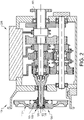
- Fig. 2 illustrate a vehicle transmission 101 according to an example embodiment.
- the vehicle transmission is arranged within a transmission housing 200.
- the vehicle transmission 101 comprises an input shaft 102 arranged to receive a torque from the prime mover (see 500 in Fig. 1 ).
- the torque from the prime mover is transmitted through the vehicle transmission 101 and out from the vehicle transmission at an output shaft 300.
- the gearwheels in the vehicle transmission 101 a plurality of gear stages are obtainable for achieving various ratios between the input shaft 102 and the output shaft 300.
- the vehicle transmission 101 comprises a transmission input shaft arrangement 100.
- the transmission input shaft arrangement 100 comprises the above described input shaft 102, a clutch arrangement 104 and a bearing arrangement 106.
- the transmission input shaft arrangement 100 may also preferably comprise a flywheel arrangement 118 which is connectable to an output shaft (not shown) of the prime mover 500.
- the flywheel arrangement 118 is connected to the input shaft via the bearing arrangement 106 at an outer end position of the input shaft 102.
- a bearing outer ring 109 of the bearing arrangement 106 is press-fitted to the flywheel arrangement 118, while a bearing inner ring 108 of the bearing arrangement 106 is loosely connected to the input shaft 102.
- loosely connected should be understood that some geometric play is present between the contact surfaces of the input shaft 102 and the bearing inner ring 108.
- the flywheel 118 rotates and the clutch arrangement 104 is arranged in a connected state in which the input shaft 102 is drivingly connected to the flywheel arrangement 118, and in turn to the output shaft of the prime mover.
- the input shaft 102 will rotate, preferably at substantially the same rotational velocity as the flywheel arrangement 118, for transmitting torque into the vehicle transmission 101.
- the clutch arrangement 104 is arranged in a disconnected state in which the input shaft 102 is disconnected from the flywheel arrangement 118.
- the flywheel arrangement 118 rotates relative to the input shaft 102.
- the bearing outer ring 109 rotates together with the flywheel arrangement 118.
- FIG. 3a - 4b illustrate two example embodiments of a transmission input shaft arrangement 100, of which the solution in Figs. 3a - 3b is illustrated without reference numerals in Fig. 2 .
- Reference is firstly made to Figs. 3a - 3b where Fig. 3a is an exploded view of the transmission input shaft arrangement 100 according to a first example embodiment, and where Fig. 3b is a cross-section of the transmission input shaft arrangement 100 in Fig. 3a in an assembled configuration.
- the transmission input shaft arrangement 100 comprises, as also described above, the input shaft 102, the flywheel arrangement 118, the bearing arrangement 106 and the clutch arrangement 104.
- the clutch arrangement 104 is depicted simply by a clutch hub for simplicity of understanding.
- the clutch hub thus forms part of the clutch arrangement 104 whereby the following will only refer to it as the clutch arrangement 104.
- the input shaft 102 comprises an outwardly facing input shaft gear teeth arrangement 116.
- the outwardly facing input shaft gear teeth arrangement 116 is preferably formed in a spline shaped configuration.
- the clutch arrangement 104 on the other hand comprises an inwardly facing gear teeth arrangement 114, also preferably formed in a spline shaped configuration. In a connected state, as depicted in Fig. 3b , the outwardly facing input shaft gear teeth arrangement 116 of the input shaft 102 is arranged in meshed connection with the inwardly facing gear teeth arrangement 114 of the clutch arrangement 104.
- the input shaft 102 comprises a bearing connecting surface 202 arranged at an outer end 204 of the input shaft 102.
- the bearing arrangement 106 is arranged to be connected to the input shaft 102 at the bearing connecting surface 202.
- an inner surface 206 of the bearing inner ring 108 is connected to the bearing connecting surface 202 of the input shaft 102.
- some geometric play is provided between the inner surface 206 of the bearing inner ring 108 and the bearing connecting surface 202 of the input shaft 102.
- the bearing outer ring 109 of the bearing arrangement 106 is connected to the flywheel arrangement 118.
- the bearing outer ring 109 is preferably fixedly connected to the flywheel arrangement 118, preferably by press-fitting an outer surface 209 of the bearing outer ring 109 and an inner flywheel surface 218 of the flywheel arrangement 118 to each other.
- the bearing inner ring 108 comprises a longitudinally extending elongated portion 110.
- the longitudinally extending elongated portion 110 thus extends in the axial direction in a direction from the flywheel arrangement 118 towards the clutch arrangement 104.
- the longitudinally extending elongated portion 110 comprises an outwardly facing gear teeth arrangement 112 at an end portion thereof.
- the outwardly facing gear teeth arrangement 112 of the bearing inner ring 108 is preferably formed in a spline shaped configuration.
- the outwardly facing gear teeth arrangement 112 of the bearing inner ring 108 is arranged in meshed connection with the inwardly facing gear teeth arrangement 114 of the clutch arrangement 104.
- the inwardly facing gear teeth arrangement 114 of the clutch arrangement 104 is arranged in meshed connection with the outwardly facing input shaft gear teeth arrangement 116 as well as the outwardly facing gear teeth arrangement 112 of the bearing inner ring 108.
- the outwardly facing gear teeth arrangement 112 of the bearing inner ring 108 is preferably forming an axially arranged inner portion 124 of the bearing inner ring 108, i.e. the axially arranged inner portion 124 is forming a part of the longitudinally extending elongated portion 110.
- the longitudinal extension 220 of the axially inner portion 124 may preferably form between 25% and 50% of the total longitudinal extension of the bearing inner ring 108. Other ranges are of course conceivable and depend, for example, on the specific vehicle transmission and its dimensions, etc.
- Figs 4a- 4b where Fig. 4a is an exploded view of the transmission input shaft arrangement 100 according to a second example embodiment, and where Fig. 4b is a cross-section of the transmission input shaft arrangement 100 in Fig. 4a in an assembled configuration. The following will only describe the differences between the first and second embodiments.
- the bearing inner ring 108 is connected to a longitudinally extending sleeve portion 126.
- the longitudinally extending sleeve portion 126 is thus a separate component which is connected to the bearing inner ring 108.
- the longitudinally extending sleeve portion 126 is preferably tightly connected to an inner surface of the bearing inner ring 108, preferably press-fitted to the bearing inner ring 108.
- a standard bearing can be used, which can be connected to the longitudinally extending sleeve portion 126 before connection to the input shaft 102.
- the bearing inner ring 108 will be rotationally connected to the clutch arrangement 104 via the longitudinally extending sleeve portion 126.
- a similar connection between the bearing arrangement 106 and the clutch arrangement 104 as described above in relation to Figs. 3a - 3b is achieved, thus preventing the relative rotation between the bearing inner ring 108 and the input shaft 102.
- the longitudinally extending sleeve portion 126 may also be advantageously used for connecting the clutch arrangement correctly, i.e. at a correct centralized position to the flywheel arrangement, such that the input shaft can be connected to the bearing inner ring. Hence, no additional tool for such operation may be required by use of the longitudinally extending sleeve portion 126.
Landscapes
- Engineering & Computer Science (AREA)
- General Engineering & Computer Science (AREA)
- Mechanical Engineering (AREA)
- Chemical & Material Sciences (AREA)
- Combustion & Propulsion (AREA)
- Transportation (AREA)
- Physics & Mathematics (AREA)
- Acoustics & Sound (AREA)
- Aviation & Aerospace Engineering (AREA)
- Mechanical Operated Clutches (AREA)
- Structure Of Transmissions (AREA)
Description
- The present invention relates to a transmission input shaft arrangement. The invention also relates to a vehicle comprising a vehicle transmission comprising such a transmission input shaft arrangement. The invention is applicable on vehicles, in particularly low/light, medium and heavy duty vehicles commonly referred to as trucks. Although the invention will mainly be described in relation to a truck, it may also be applicable for other types of vehicles such as e.g. working machines, buses, etc.
- In connection to low/light-, medium and heavy duty vehicles, also commonly referred to as trucks, a transmission arrangement is connected to a prime mover for controlling torque loads from the prime mover to the propelled wheels of the truck. Hereby, a variety of ratios between the input shaft and the output shaft of the transmission arrangement can be obtained.
- The transmission arrangement is conventionally connected to an output shaft of the prime mover via a flywheel and a clutch arrangement. In detail, torque loads from the prime mover are provided to the flywheel. For transmitting the torque loads from the flywheel to the input shaft, the clutch arrangement is arranged in an engaged state, whereby torque loads can be further directed through the transmission.
- Moreover, the transmission arrangement most often comprises a bearing arrangement between the flywheel and the input shaft for supporting the flywheel at the end portion of the input shaft. During assembly of the transmission arrangement to the engine, the bearing arrangement is preferably fixedly connected to the flywheel. Hence, the bearing outer ring is fixedly connected to the flywheel. Thereafter, the flywheel/bearing assembly is connected to the input shaft.
- A problem with the above procedure is that the bearing inner ring cannot be fixedly connected to the input shaft. This may in turn cause a possible relative rotation between the bearing inner ring of the bearing arrangement and the input shaft. Such situation may arise when the flywheel is rotating and the clutch arrangement is arranged in a disconnected state, i.e. when there is a speed difference between the flywheel and the input shaft. Such relative rotation between the bearing inner ring and the input shaft may in turn cause wear on the bearing arrangement as well as the input shaft.
- According to its abstract,
DE 43 07 830 describes that a sleeve-like section engages over the outer race and is connected to an annular section, which extends on the axial side of the bearing radially towards the inner race. Further,JP 2003 148484 JP 203 060194 - There is thus a desire to reduce the relative rotation between such bearing and the input shaft of a transmission arrangement.
- It is an object of the present invention to provide a transmission input shaft arrangement which at least partially overcomes the above described deficiencies. This is achieved by a transmission input shaft arrangement according to claim 1.
- According to a first aspect, there is provided a transmission input shaft arrangement for a vehicle transmission, the transmission input shaft arrangement comprising an input shaft; a clutch arrangement connected to the input shaft and controllable between a first state in which the input shaft is drivingly connected to an output shaft of a prime mover, and a second state in which the input shaft is disconnected from the output shaft of the prime mover; and a bearing arrangement comprising a bearing inner ring connected to the input shaft and arranged at a position spaced apart from the clutch arrangement in the longitudinal direction of the input shaft, wherein the bearing inner ring is rotationally connected to the clutch arrangement.
- The bearing inner ring should be construed as an inner radially positioned bearing ring. The bearing inner ring preferably comprises an inner raceway at which roller elements of the bearing can be provided. The present disclosure should not be construed as limited to any specific type of bearing arrangement.
- Moreover, the wording "clutch arrangement connected to the input shaft" may also be understood as a portion of the clutch arrangement being fixedly connected, at least in the rotational direction, to the input shaft. Hence, one connecting member of the clutch arrangement is preferably fixedly connected in the rotational direction to the input shaft.
- An advantage is that the bearing arrangement can be loosely connected to the input shaft while still being prevented from rotating relative to the clutch arrangement. As the clutch arrangement comprises a portion rotationally connected to the input shaft, a mutual rotation between the bearing inner ring and the input shaft is thus also prevented. Reduced wear on the bearing arrangement as well as the input shaft is thus achieved. Also, a relatively simple assembly of the bearing arrangement to the input shaft is achieved. There are different approaches of rotationally connecting the bearing inner ring to the clutch arrangement, which will be described further below. The wording "rotationally connected" should thus be understood such that a mutual rotation between the bearing inner ring and the clutch arrangement is prevented. Accordingly, no additional rotational fixation of the inner bearing ring to the input shaft is required as the bearing ring instead is connected to the clutch arrangement. This will also reduce the risk of accidentally damaging the bearing arrangement during assembly thereof.
- According to the invention, the input shaft comprises an outwardly facing input shaft gear teeth arrangement arranged in meshed connection with the inwardly facing gear teeth arrangement of the clutch arrangement.
- According to an example embodiment, the transmission input shaft arrangement may further comprise a vehicle flywheel arrangement, the flywheel arrangement being connectable to the output shaft of the prime mover and arranged to transmit a torque from the output shaft of the prime mover to the input shaft via the clutch arrangement.
- According to an example embodiment, the bearing arrangement may be connected between the input shaft and the vehicle flywheel arrangement.
- Hence, a meshed connection, as will be described further below, between an outwardly facing gear teeth arrangement of the bearing inner ring and an inwardly facing gear teeth arrangement of the clutch arrangement may prevent a relative rotation of the bearing inner ring and the input shaft when the input shaft is disconnected from the output shaft of the prime mover.
- According to an example embodiment, the bearing arrangement may comprise a bearing outer ring, the bearing outer ring being press-fitted to the vehicle flywheel arrangement. Hereby, a tight fit is provided. Also, the connection between the flywheel arrangement and the bearing arrangement can be made in advance, where after the flywheel/bearing assembly is connected to the input shaft.
- According to the first aspect of the invention, the bearing inner ring comprises a longitudinally extending elongated portion extending from an outer end portion of the input shaft to a position radially below a portion of the clutch arrangement, wherein the longitudinally extending elongated portion comprises an outwardly facing gear teeth arrangement arranged in meshed connection with an inwardly facing gear teeth arrangement of the clutch arrangement.
- The wording inwardly and outwardly facing gear teeth should be construed as seen in the radial direction. Hence, inwardly facing gear teeth are facing radially inwardly, while outwardly facing gear teeth are facing radially outwardly.
- Furthermore, providing the bearing inner ring with outwardly facing gear teeth in meshed connection with inwardly facing gear teeth of the clutch arrangement will prevent the relative rotation without the need of tightly fixate the bearing inner ring to the input shaft, which is most often associated with the use of narrow tolerances achieved by expensive machining.
- Accordingly, the outwardly facing gear teeth of the bearing inner ring and the outwardly facing gear teeth of the input shaft may be arranged in meshed connection with the same inwardly facing gear teeth arrangement of the clutch arrangement, although at different axial positions. The inwardly facing gear teeth arrangement of the clutch arrangement may thus preferably extend an axial distance from the connection to the outwardly facing gear teeth arrangement of the input shaft.
- Also, the flywheel arrangement can be arranged at a sufficient distance from the clutch arrangement while still enabling the connection between the bearing inner ring and the clutch arrangement.
- According to an example embodiment, the outwardly facing gear teeth arrangement of the bearing inner ring may form an axially arranged inner portion of the bearing inner ring, wherein a longitudinal extension of the axially arranged inner portion forms less than 50% of a longitudinal extension of the bearing inner ring.
- According to an example embodiment, the longitudinal extension of the axially arranged inner portion may form at least 25% of the longitudinal extension of the bearing inner ring.
- Hereby, a sufficient connection between the outwardly facing gear teeth arrangement of the bearing inner ring and the inwardly facing gear teeth arrangement of the clutch arrangement can be achieved.
- According to an example embodiment, the bearing arrangement may be positioned at an outer end position of the input shaft.
- According to an example embodiment, the bearing inner ring may be non-fixedly connected to the input shaft for allowing a mutual rotation between the inner bearing and the input shaft.
- The wording "non-fixedly connected" should be construed such that the bearing inner ring would be allowed to rotate relative the input shaft if not rotationally connected to the clutch arrangement. The bearing inner ring is thus rotationally non-fixedly connected to the input shaft.
- According to a second aspect of the invention, the transmission input shaft arrangement further comprises a longitudinally extending sleeve portion connected to the bearing inner ring, wherein the longitudinally extending sleeve portion comprises an outwardly facing gear teeth arrangement arranged in meshed connection with an inwardly facing gear teeth arrangement of the clutch arrangement.
- The longitudinally extending sleeve portion may preferably be fixedly connected, at least in the rotational direction to the bearing inner ring. An effect of the longitudinally extending sleeve portion is that the bearing inner ring itself needs no substantial design modification. Also, the sleeve may be provided from a material which is cheaper to produce in comparison to the material of the bearing inner ring.
- According to an example embodiment, the longitudinally extending sleeve portion may be press-fitted to the bearing inner ring.
- According to an example embodiment, the outwardly facing gear teeth arrangement and the inwardly facing gear teeth arrangement of the clutch arrangement may comprise respective gear teeth, wherein each gear tooth is formed in a spline shaped configuration.
- A spline connection is advantageous as it can efficiently transmit torque loads between the parts it connects.
- According to a third aspect, there is provided a vehicle comprising a vehicle transmission and a prime mover arranged to provide a propelling torque to the vehicle transmission, wherein the vehicle transmission comprises a transmission input shaft arrangement according to any one of the embodiments described above in relation to the first aspect.
- Further features of, and advantages with, the present invention will become apparent when studying the appended claims and the following description. The skilled person will realize that different features of the present invention may be combined to create embodiments other than those described in the following, without departing from the scope of the present invention.
- The above, as well as additional objects, features and advantages of the present invention, will be better understood through the following illustrative and non-limiting detailed description of exemplary embodiments of the present invention, wherein:
-
Fig. 1 is a lateral side view illustrating an example embodiment of a vehicle in the form of a truck; -
Fig. 2 is a schematic illustration of a vehicle transmission according to an example embodiment; -
Figs. 3a - 3b illustrate a transmission input shaft arrangement according to an example embodiment; and -
Figs. 4a - 4b illustrate a transmission input shaft arrangement according to another example embodiment. - The present invention will now be described more fully hereinafter with reference to the accompanying drawings, in which exemplary embodiments of the invention are shown. The invention may, however, be embodied in many different forms and should not be construed as limited to the embodiments set forth herein; rather, these embodiments are provided for thoroughness and completeness. Like reference characters refer to like elements throughout the description.
- With particular reference to
Fig. 1 , there is provided a vehicle 1 in the form of a truck. The vehicle 1 comprises aprime mover 500 in the form of an internalcombustion engine arrangement 500, and avehicle transmission 101 connected to theprime mover 500. The vehicle 1 inFig. 1 is particularly suitable for utilizing avehicle transmission 101 described below in relation to the description ofFig. 2 . - Reference is therefore made to
Fig. 2 , which illustrate avehicle transmission 101 according to an example embodiment. The vehicle transmission is arranged within atransmission housing 200. Furthermore, thevehicle transmission 101 comprises aninput shaft 102 arranged to receive a torque from the prime mover (see 500 inFig. 1 ). The torque from the prime mover is transmitted through thevehicle transmission 101 and out from the vehicle transmission at anoutput shaft 300. By means of the gearwheels in thevehicle transmission 101, a plurality of gear stages are obtainable for achieving various ratios between theinput shaft 102 and theoutput shaft 300. - Moreover, the
vehicle transmission 101 comprises a transmissioninput shaft arrangement 100. In particular, the transmissioninput shaft arrangement 100 comprises the above describedinput shaft 102, aclutch arrangement 104 and abearing arrangement 106. The transmissioninput shaft arrangement 100 may also preferably comprise aflywheel arrangement 118 which is connectable to an output shaft (not shown) of theprime mover 500. Theflywheel arrangement 118 is connected to the input shaft via thebearing arrangement 106 at an outer end position of theinput shaft 102. Preferably, a bearingouter ring 109 of thebearing arrangement 106 is press-fitted to theflywheel arrangement 118, while a bearinginner ring 108 of thebearing arrangement 106 is loosely connected to theinput shaft 102. By loosely connected should be understood that some geometric play is present between the contact surfaces of theinput shaft 102 and the bearinginner ring 108. - When transmitting torque from the
prime mover 500 to thevehicle transmission 101, theflywheel 118 rotates and theclutch arrangement 104 is arranged in a connected state in which theinput shaft 102 is drivingly connected to theflywheel arrangement 118, and in turn to the output shaft of the prime mover. Hereby, theinput shaft 102 will rotate, preferably at substantially the same rotational velocity as theflywheel arrangement 118, for transmitting torque into thevehicle transmission 101. - On the other hand, when the
vehicle transmission 101 is disconnected from theprime mover 500, theclutch arrangement 104 is arranged in a disconnected state in which theinput shaft 102 is disconnected from theflywheel arrangement 118. In this state, theflywheel arrangement 118 rotates relative to theinput shaft 102. In detail, the bearingouter ring 109 rotates together with theflywheel arrangement 118. - In the latter situation, i.e. when the
clutch arrangement 104 is arranged in the disconnected state, there is thus a speed difference between the rotational velocity of theinput shaft 102 and the rotational velocity of theflywheel arrangement 118. - Due to this relative rotation, and the fact that the bearing
inner ring 108 is connected to theinput shaft 102 with the above described geometric play, there is a risk that the bearinginner ring 108 will rotate relative to theinput shaft 102, i.e. a mutual displacement between the bearinginner ring 108 and theinput shaft 102 may arise. This may cause wear on components, such as the contact surfaces of the bearinginner ring 108 and theinput shaft 102, etc. - A solution to such problem is depicted in detail in
Figs. 3a - 4b , which illustrate two example embodiments of a transmissioninput shaft arrangement 100, of which the solution inFigs. 3a - 3b is illustrated without reference numerals inFig. 2 . Reference is firstly made toFigs. 3a - 3b , whereFig. 3a is an exploded view of the transmissioninput shaft arrangement 100 according to a first example embodiment, and whereFig. 3b is a cross-section of the transmissioninput shaft arrangement 100 inFig. 3a in an assembled configuration. - As can be seen in
Figs. 3a - 3b , the transmissioninput shaft arrangement 100 comprises, as also described above, theinput shaft 102, theflywheel arrangement 118, thebearing arrangement 106 and theclutch arrangement 104. Theclutch arrangement 104 is depicted simply by a clutch hub for simplicity of understanding. The clutch hub thus forms part of theclutch arrangement 104 whereby the following will only refer to it as theclutch arrangement 104. - Furthermore, the
input shaft 102 comprises an outwardly facing input shaftgear teeth arrangement 116. The outwardly facing input shaftgear teeth arrangement 116 is preferably formed in a spline shaped configuration. Theclutch arrangement 104 on the other hand comprises an inwardly facinggear teeth arrangement 114, also preferably formed in a spline shaped configuration. In a connected state, as depicted inFig. 3b , the outwardly facing input shaftgear teeth arrangement 116 of theinput shaft 102 is arranged in meshed connection with the inwardly facinggear teeth arrangement 114 of theclutch arrangement 104. - Still further, the
input shaft 102 comprises abearing connecting surface 202 arranged at anouter end 204 of theinput shaft 102. Thebearing arrangement 106 is arranged to be connected to theinput shaft 102 at thebearing connecting surface 202. In detail, aninner surface 206 of the bearinginner ring 108 is connected to thebearing connecting surface 202 of theinput shaft 102. As described above, some geometric play is provided between theinner surface 206 of the bearinginner ring 108 and thebearing connecting surface 202 of theinput shaft 102. - Moreover, the bearing
outer ring 109 of thebearing arrangement 106 is connected to theflywheel arrangement 118. In detail, the bearingouter ring 109 is preferably fixedly connected to theflywheel arrangement 118, preferably by press-fitting an outer surface 209 of the bearingouter ring 109 and aninner flywheel surface 218 of theflywheel arrangement 118 to each other. - With particular reference to the
bearing arrangement 106, the bearinginner ring 108 comprises a longitudinally extendingelongated portion 110. The longitudinally extendingelongated portion 110 thus extends in the axial direction in a direction from theflywheel arrangement 118 towards theclutch arrangement 104. The longitudinally extendingelongated portion 110 comprises an outwardly facinggear teeth arrangement 112 at an end portion thereof. The outwardly facinggear teeth arrangement 112 of the bearinginner ring 108 is preferably formed in a spline shaped configuration. Moreover, and as best illustrated in the enlarged portion ofFig. 3b , the outwardly facinggear teeth arrangement 112 of the bearinginner ring 108 is arranged in meshed connection with the inwardly facinggear teeth arrangement 114 of theclutch arrangement 104. Accordingly, the inwardly facinggear teeth arrangement 114 of theclutch arrangement 104 is arranged in meshed connection with the outwardly facing input shaftgear teeth arrangement 116 as well as the outwardly facinggear teeth arrangement 112 of the bearinginner ring 108. - The outwardly facing
gear teeth arrangement 112 of the bearinginner ring 108 is preferably forming an axially arrangedinner portion 124 of the bearinginner ring 108, i.e. the axially arrangedinner portion 124 is forming a part of the longitudinally extendingelongated portion 110. Thelongitudinal extension 220 of the axiallyinner portion 124 may preferably form between 25% and 50% of the total longitudinal extension of the bearinginner ring 108. Other ranges are of course conceivable and depend, for example, on the specific vehicle transmission and its dimensions, etc. - By means of the connection between the outwardly facing
gear teeth arrangement 112 of the bearinginner ring 108 and the inwardly facinggear teeth arrangement 114 of theclutch arrangement 104, the relative rotation between the bearinginner ring 108 and theinput shaft 102 is prevented. Hereby, wear of components will be reduced. - Reference is now made to
Figs 4a- 4b , whereFig. 4a is an exploded view of the transmissioninput shaft arrangement 100 according to a second example embodiment, and whereFig. 4b is a cross-section of the transmissioninput shaft arrangement 100 inFig. 4a in an assembled configuration. The following will only describe the differences between the first and second embodiments. - With particular reference to the enlarged portion of
Fig. 4b , the bearinginner ring 108 is connected to a longitudinally extendingsleeve portion 126. The longitudinally extendingsleeve portion 126 is thus a separate component which is connected to the bearinginner ring 108. The longitudinally extendingsleeve portion 126 is preferably tightly connected to an inner surface of the bearinginner ring 108, preferably press-fitted to the bearinginner ring 108. Hereby, a standard bearing can be used, which can be connected to the longitudinally extendingsleeve portion 126 before connection to theinput shaft 102. Hereby, the bearinginner ring 108 will be rotationally connected to theclutch arrangement 104 via the longitudinally extendingsleeve portion 126. Accordingly, instead of the above described longitudinally extending elongated portion of the bearinginner ring 108, such longitudinal extension is formed by the longitudinally extendingsleeve portion 126. Hence, the outwardly facinggear teeth arrangement 112 is arranged on the longitudinally extendingsleeve portion 126 and numbered similar as the above outwardly facinggear teeth arrangement 112 of the bearinginner ring 108. - By means of the arrangement depicted in
Figs. 4a - 4b , a similar connection between thebearing arrangement 106 and theclutch arrangement 104 as described above in relation toFigs. 3a - 3b is achieved, thus preventing the relative rotation between the bearinginner ring 108 and theinput shaft 102. The longitudinally extendingsleeve portion 126 may also be advantageously used for connecting the clutch arrangement correctly, i.e. at a correct centralized position to the flywheel arrangement, such that the input shaft can be connected to the bearing inner ring. Hence, no additional tool for such operation may be required by use of the longitudinally extendingsleeve portion 126. - It is to be understood that the present invention is not limited to the embodiments described above and illustrated in the drawings; rather, the skilled person will recognize that many changes and modifications may be made within the scope of the appended claims.
Claims (12)
- A transmission input shaft arrangement (100) for a vehicle transmission, the transmission input shaft arrangement comprising:- an input shaft (102);- a clutch arrangement (104) connected to the input shaft (102) and controllable between a first state in which the input shaft (102) is drivingly connected to an output shaft of a prime mover, and a second state in which the input shaft (102) is disconnected from the output shaft of the prime mover, wherein the input shaft (102) comprises an outwardly facing input shaft gear teeth arrangement (116) arranged in meshed connection with an inwardly facing gear teeth arrangement (114) of the clutch arrangement (104); and- a bearing arrangement (106) comprising a bearing inner ring (108) connected to the input shaft and arranged at a position spaced apart from the clutch arrangement (104) in the longitudinal direction of the input shaft (102), characterized in that the bearing inner ring (108) is rotationally connected to the clutch arrangement (114)wherein the bearing inner ring (108) comprises a longitudinally extending elongated portion (110) extending from an outer end portion (204) of the input shaft (102) to a position below a portion of the clutch arrangement (104) as seen in the radial direction, wherein the longitudinally extending elongated portion (110) comprises an outwardly facing gear teeth arrangement (112) arranged in meshed connection with an inwardly facing gear teeth arrangement (114) of the clutch arrangement (104).
- The transmission input shaft arrangement according to claim 1, further comprising a vehicle flywheel arrangement (118), the flywheel arrangement (118) being connectable to the output shaft of the prime mover and arranged to transmit a torque from the output shaft of the prime mover to the input shaft (102) via the clutch arrangement (104).
- The transmission input shaft arrangement according to claim 2, wherein the bearing arrangement (106) is connected between the input shaft (102) and the vehicle flywheel arrangement (118).
- The transmission input shaft arrangement according to claim 3, wherein the bearing arrangement (106) comprises a bearing outer ring (120), the bearing outer ring (120) being press-fitted to the vehicle flywheel arrangement (118).
- The transmission input shaft arrangement according to claim 4, wherein the outwardly facing gear teeth arrangement (112) of the bearing inner ring (108) is forming an axially arranged inner portion (124) of the bearing inner ring, wherein a longitudinal extension of the axially arranged inner portion (124) forms less than 50% of a longitudinal extension of the bearing inner ring (108).
- The transmission input shaft arrangement according to claim 5 wherein the longitudinal extension of the axially arranged inner portion (124) forms at least 25% of the longitudinal extension of the bearing inner ring.
- The transmission input shaft arrangement according to any one of the preceding claims, wherein the bearing arrangement (106) is positioned at an outer end position (204) of the input shaft (102).
- The transmission input shaft arrangement according to any one of the preceding claims, wherein the bearing inner ring (108) is non-fixedly connected to the input shaft (102) for allowing a mutual rotation between the inner bearing (108) and the input shaft (102).
- A transmission input shaft arrangement (100) for a vehicle transmission, the transmission input shaft arrangement comprising:- an input shaft (102);- a clutch arrangement (104) connected to the input shaft (102) and controllable between a first state in which the input shaft (102) is drivingly connected to an output shaft of a prime mover, and a second state in which the input shaft (102) is disconnected from the output shaft of the prime mover, wherein the input shaft (102) comprises an outwardly facing input shaft gear teeth arrangement (116) arranged in meshed connection with the inwardly facing gear teeth arrangement (114) of the clutch arrangement (104); and- a bearing arrangement (106) comprising a bearing inner ring (108) connected to the input shaft and arranged at a position spaced apart from the clutch arrangement (104) in the longitudinal direction of the input shaft (102),characterized in that the bearing inner ring (108) is rotationally connected to the clutch arrangement (114) further comprising a longitudinally extending sleeve portion (126) connected to the bearing inner ring (108), wherein the longitudinally extending sleeve portion (126) comprises an outwardly facing gear teeth arrangement (112) arranged in meshed connection with an inwardly facing gear teeth arrangement (114) of the clutch arrangement (104).
- The transmission input shaft arrangement according to claim 9 wherein the longitudinally extending sleeve portion (126) is press-fitted to the bearing inner ring (108).
- The transmission input shaft arrangement according to any one of claims 4 - 10, wherein the outwardly facing gear teeth arrangement (112) and the inwardly facing gear teeth arrangement (114) of the clutch arrangement comprises respective gear teeth, wherein each gear tooth is formed in a spline shaped configuration.
- A vehicle (1) comprising a vehicle transmission (101) and a prime mover (500) arranged to provide a propelling torque to the vehicle transmission, wherein the vehicle transmission comprises a transmission input shaft arrangement according to any one of the preceding claims.
Applications Claiming Priority (1)
| Application Number | Priority Date | Filing Date | Title |
|---|---|---|---|
| PCT/EP2017/078841 WO2019091564A1 (en) | 2017-11-10 | 2017-11-10 | Transmission input shaft arrangement |
Publications (2)
| Publication Number | Publication Date |
|---|---|
| EP3707400A1 EP3707400A1 (en) | 2020-09-16 |
| EP3707400B1 true EP3707400B1 (en) | 2023-01-04 |
Family
ID=60293969
Family Applications (1)
| Application Number | Title | Priority Date | Filing Date |
|---|---|---|---|
| EP17797149.6A Active EP3707400B1 (en) | 2017-11-10 | 2017-11-10 | Transmission input shaft arrangement |
Country Status (4)
| Country | Link |
|---|---|
| US (1) | US11371555B2 (en) |
| EP (1) | EP3707400B1 (en) |
| CN (1) | CN111356850B (en) |
| WO (1) | WO2019091564A1 (en) |
Family Cites Families (18)
| Publication number | Priority date | Publication date | Assignee | Title |
|---|---|---|---|---|
| DE4307830B4 (en) * | 1992-03-17 | 2013-11-07 | Schaeffler Technologies AG & Co. KG | roller bearing |
| US5269607A (en) | 1992-06-29 | 1993-12-14 | The Torrington Company | Bearing assembly with locking device |
| JP2003148484A (en) | 2001-11-12 | 2003-05-21 | Nsk Ltd | Bearing device |
| JP3732166B2 (en) * | 2002-08-22 | 2006-01-05 | 株式会社シマノ | Bicycle hub |
| EP1609654B1 (en) * | 2004-06-21 | 2008-11-05 | LuK Lamellen und Kupplungsbau Beteiligungs KG | Torque transfer device |
| CN100491776C (en) * | 2004-09-23 | 2009-05-27 | 通用汽车环球科技运作公司 | vehicle gearbox |
| US7503698B2 (en) | 2006-05-01 | 2009-03-17 | Rexnord Industries, Llc | Wedge-type bearing assembly |
| US20080144986A1 (en) | 2006-09-29 | 2008-06-19 | Roman Michael Wajda | Sleeve mounting system and method |
| JP2008189212A (en) | 2007-02-07 | 2008-08-21 | Ntn Corp | In-wheel motor driving device |
| DE102007016427B4 (en) * | 2007-04-05 | 2010-11-25 | Schaeffler Technologies Gmbh & Co. Kg | Bearing arrangement of a driven via a rotary hub of a motor vehicle |
| CN201382085Y (en) * | 2008-11-24 | 2010-01-13 | 新昌县开源汽车轴承有限公司 | Integrated automobile wheel hub bearing unit |
| JP5366665B2 (en) * | 2009-06-03 | 2013-12-11 | Ntn株式会社 | Wheel bearing device |
| WO2012021594A2 (en) * | 2010-08-13 | 2012-02-16 | Allison Transmission, Inc. | Housing with a direct flow path for hardware lubrication |
| US20130257005A1 (en) * | 2012-03-27 | 2013-10-03 | The Timken Company | Compact wheel end with coupler |
| CN102588463A (en) * | 2012-03-30 | 2012-07-18 | 湖南大学 | Improved actuating mechanism of clutch |
| JP5435102B2 (en) | 2012-10-22 | 2014-03-05 | 株式会社ジェイテクト | Wheel bearing device |
| CN205136366U (en) | 2015-11-11 | 2016-04-06 | 浙江博盟精工机械有限公司 | Take tooth disjunctor bearing |
| CN206180768U (en) * | 2016-09-09 | 2017-05-17 | 精进电动科技股份有限公司 | Motor and retarder connection's input shaft structure |
-
2017
- 2017-11-10 CN CN201780096627.3A patent/CN111356850B/en active Active
- 2017-11-10 US US16/760,309 patent/US11371555B2/en active Active
- 2017-11-10 EP EP17797149.6A patent/EP3707400B1/en active Active
- 2017-11-10 WO PCT/EP2017/078841 patent/WO2019091564A1/en not_active Ceased
Also Published As
| Publication number | Publication date |
|---|---|
| US11371555B2 (en) | 2022-06-28 |
| WO2019091564A1 (en) | 2019-05-16 |
| CN111356850B (en) | 2021-11-23 |
| EP3707400A1 (en) | 2020-09-16 |
| US20200271157A1 (en) | 2020-08-27 |
| CN111356850A (en) | 2020-06-30 |
Similar Documents
| Publication | Publication Date | Title |
|---|---|---|
| US9797495B2 (en) | Clutch and differential device with same | |
| US10443657B2 (en) | Power transmission device for vehicle | |
| EP3453906B1 (en) | Joint for torque transmission and electric power steering device | |
| JP6485543B2 (en) | Torque transmission joint and worm reducer | |
| EP3126690B1 (en) | Rotating shaft coupling | |
| US9869370B2 (en) | Gearbox for a vehicle and vehicle, comprising such a gearbox | |
| CN109990048A (en) | planetary transmission | |
| CN112829824B (en) | Electric Power Steering Polymer Drive Pulley | |
| JP2009150545A (en) | Manual transmission | |
| US11603907B2 (en) | Gearwheel transmission | |
| EP3707400B1 (en) | Transmission input shaft arrangement | |
| KR20230063867A (en) | Plug-in shaft arrangement and hub-reduction axle for a motor vehicle | |
| US20190136959A1 (en) | Locking bearing assembly | |
| US11215271B2 (en) | Toothing arrangement | |
| CN110300860B (en) | Bearing arrangement and assembly comprising such bearing arrangement | |
| KR20100008471A (en) | Hybrid transmission of vehicle and assembly method thereof | |
| US20190257362A1 (en) | Tripod roller for a constant velocity universal joint | |
| EP3203119A1 (en) | Gear assembly | |
| JP5283832B2 (en) | Constant velocity universal joint | |
| JP2012219976A (en) | Clutch drum of automatic transmission for vehicle | |
| EP3581417B1 (en) | A transmission for a vehicle | |
| US20200317047A1 (en) | Motor Vehicle Drive Shaft and Method for Producing It | |
| JP2010031910A (en) | Outside joint member of constant velocity universal joint and constant velocity universal joint | |
| JP2019152281A (en) | Coupling device | |
| KR20170039880A (en) | companion flange intergrated bearing |
Legal Events
| Date | Code | Title | Description |
|---|---|---|---|
| STAA | Information on the status of an ep patent application or granted ep patent |
Free format text: STATUS: UNKNOWN |
|
| STAA | Information on the status of an ep patent application or granted ep patent |
Free format text: STATUS: THE INTERNATIONAL PUBLICATION HAS BEEN MADE |
|
| PUAI | Public reference made under article 153(3) epc to a published international application that has entered the european phase |
Free format text: ORIGINAL CODE: 0009012 |
|
| STAA | Information on the status of an ep patent application or granted ep patent |
Free format text: STATUS: REQUEST FOR EXAMINATION WAS MADE |
|
| 17P | Request for examination filed |
Effective date: 20200424 |
|
| AK | Designated contracting states |
Kind code of ref document: A1 Designated state(s): AL AT BE BG CH CY CZ DE DK EE ES FI FR GB GR HR HU IE IS IT LI LT LU LV MC MK MT NL NO PL PT RO RS SE SI SK SM TR |
|
| AX | Request for extension of the european patent |
Extension state: BA ME |
|
| DAV | Request for validation of the european patent (deleted) | ||
| DAX | Request for extension of the european patent (deleted) | ||
| GRAP | Despatch of communication of intention to grant a patent |
Free format text: ORIGINAL CODE: EPIDOSNIGR1 |
|
| STAA | Information on the status of an ep patent application or granted ep patent |
Free format text: STATUS: GRANT OF PATENT IS INTENDED |
|
| INTG | Intention to grant announced |
Effective date: 20220204 |
|
| GRAJ | Information related to disapproval of communication of intention to grant by the applicant or resumption of examination proceedings by the epo deleted |
Free format text: ORIGINAL CODE: EPIDOSDIGR1 |
|
| STAA | Information on the status of an ep patent application or granted ep patent |
Free format text: STATUS: REQUEST FOR EXAMINATION WAS MADE |
|
| INTC | Intention to grant announced (deleted) | ||
| GRAP | Despatch of communication of intention to grant a patent |
Free format text: ORIGINAL CODE: EPIDOSNIGR1 |
|
| STAA | Information on the status of an ep patent application or granted ep patent |
Free format text: STATUS: GRANT OF PATENT IS INTENDED |
|
| INTG | Intention to grant announced |
Effective date: 20220801 |
|
| GRAS | Grant fee paid |
Free format text: ORIGINAL CODE: EPIDOSNIGR3 |
|
| GRAA | (expected) grant |
Free format text: ORIGINAL CODE: 0009210 |
|
| STAA | Information on the status of an ep patent application or granted ep patent |
Free format text: STATUS: THE PATENT HAS BEEN GRANTED |
|
| AK | Designated contracting states |
Kind code of ref document: B1 Designated state(s): AL AT BE BG CH CY CZ DE DK EE ES FI FR GB GR HR HU IE IS IT LI LT LU LV MC MK MT NL NO PL PT RO RS SE SI SK SM TR |
|
| REG | Reference to a national code |
Ref country code: GB Ref legal event code: FG4D |
|
| REG | Reference to a national code |
Ref country code: CH Ref legal event code: EP |
|
| REG | Reference to a national code |
Ref country code: AT Ref legal event code: REF Ref document number: 1542136 Country of ref document: AT Kind code of ref document: T Effective date: 20230115 |
|
| REG | Reference to a national code |
Ref country code: DE Ref legal event code: R096 Ref document number: 602017065237 Country of ref document: DE |
|
| REG | Reference to a national code |
Ref country code: IE Ref legal event code: FG4D |
|
| REG | Reference to a national code |
Ref country code: LT Ref legal event code: MG9D |
|
| REG | Reference to a national code |
Ref country code: NL Ref legal event code: MP Effective date: 20230104 |
|
| REG | Reference to a national code |
Ref country code: AT Ref legal event code: MK05 Ref document number: 1542136 Country of ref document: AT Kind code of ref document: T Effective date: 20230104 |
|
| PG25 | Lapsed in a contracting state [announced via postgrant information from national office to epo] |
Ref country code: NL Free format text: LAPSE BECAUSE OF FAILURE TO SUBMIT A TRANSLATION OF THE DESCRIPTION OR TO PAY THE FEE WITHIN THE PRESCRIBED TIME-LIMIT Effective date: 20230104 |
|
| PG25 | Lapsed in a contracting state [announced via postgrant information from national office to epo] |
Ref country code: RS Free format text: LAPSE BECAUSE OF FAILURE TO SUBMIT A TRANSLATION OF THE DESCRIPTION OR TO PAY THE FEE WITHIN THE PRESCRIBED TIME-LIMIT Effective date: 20230104 Ref country code: PT Free format text: LAPSE BECAUSE OF FAILURE TO SUBMIT A TRANSLATION OF THE DESCRIPTION OR TO PAY THE FEE WITHIN THE PRESCRIBED TIME-LIMIT Effective date: 20230504 Ref country code: NO Free format text: LAPSE BECAUSE OF FAILURE TO SUBMIT A TRANSLATION OF THE DESCRIPTION OR TO PAY THE FEE WITHIN THE PRESCRIBED TIME-LIMIT Effective date: 20230404 Ref country code: LV Free format text: LAPSE BECAUSE OF FAILURE TO SUBMIT A TRANSLATION OF THE DESCRIPTION OR TO PAY THE FEE WITHIN THE PRESCRIBED TIME-LIMIT Effective date: 20230104 Ref country code: LT Free format text: LAPSE BECAUSE OF FAILURE TO SUBMIT A TRANSLATION OF THE DESCRIPTION OR TO PAY THE FEE WITHIN THE PRESCRIBED TIME-LIMIT Effective date: 20230104 Ref country code: HR Free format text: LAPSE BECAUSE OF FAILURE TO SUBMIT A TRANSLATION OF THE DESCRIPTION OR TO PAY THE FEE WITHIN THE PRESCRIBED TIME-LIMIT Effective date: 20230104 Ref country code: ES Free format text: LAPSE BECAUSE OF FAILURE TO SUBMIT A TRANSLATION OF THE DESCRIPTION OR TO PAY THE FEE WITHIN THE PRESCRIBED TIME-LIMIT Effective date: 20230104 Ref country code: AT Free format text: LAPSE BECAUSE OF FAILURE TO SUBMIT A TRANSLATION OF THE DESCRIPTION OR TO PAY THE FEE WITHIN THE PRESCRIBED TIME-LIMIT Effective date: 20230104 |
|
| PG25 | Lapsed in a contracting state [announced via postgrant information from national office to epo] |
Ref country code: SE Free format text: LAPSE BECAUSE OF FAILURE TO SUBMIT A TRANSLATION OF THE DESCRIPTION OR TO PAY THE FEE WITHIN THE PRESCRIBED TIME-LIMIT Effective date: 20230104 Ref country code: PL Free format text: LAPSE BECAUSE OF FAILURE TO SUBMIT A TRANSLATION OF THE DESCRIPTION OR TO PAY THE FEE WITHIN THE PRESCRIBED TIME-LIMIT Effective date: 20230104 Ref country code: IS Free format text: LAPSE BECAUSE OF FAILURE TO SUBMIT A TRANSLATION OF THE DESCRIPTION OR TO PAY THE FEE WITHIN THE PRESCRIBED TIME-LIMIT Effective date: 20230504 Ref country code: GR Free format text: LAPSE BECAUSE OF FAILURE TO SUBMIT A TRANSLATION OF THE DESCRIPTION OR TO PAY THE FEE WITHIN THE PRESCRIBED TIME-LIMIT Effective date: 20230405 Ref country code: FI Free format text: LAPSE BECAUSE OF FAILURE TO SUBMIT A TRANSLATION OF THE DESCRIPTION OR TO PAY THE FEE WITHIN THE PRESCRIBED TIME-LIMIT Effective date: 20230104 |
|
| REG | Reference to a national code |
Ref country code: DE Ref legal event code: R097 Ref document number: 602017065237 Country of ref document: DE |
|
| PG25 | Lapsed in a contracting state [announced via postgrant information from national office to epo] |
Ref country code: SM Free format text: LAPSE BECAUSE OF FAILURE TO SUBMIT A TRANSLATION OF THE DESCRIPTION OR TO PAY THE FEE WITHIN THE PRESCRIBED TIME-LIMIT Effective date: 20230104 Ref country code: RO Free format text: LAPSE BECAUSE OF FAILURE TO SUBMIT A TRANSLATION OF THE DESCRIPTION OR TO PAY THE FEE WITHIN THE PRESCRIBED TIME-LIMIT Effective date: 20230104 Ref country code: EE Free format text: LAPSE BECAUSE OF FAILURE TO SUBMIT A TRANSLATION OF THE DESCRIPTION OR TO PAY THE FEE WITHIN THE PRESCRIBED TIME-LIMIT Effective date: 20230104 Ref country code: DK Free format text: LAPSE BECAUSE OF FAILURE TO SUBMIT A TRANSLATION OF THE DESCRIPTION OR TO PAY THE FEE WITHIN THE PRESCRIBED TIME-LIMIT Effective date: 20230104 Ref country code: CZ Free format text: LAPSE BECAUSE OF FAILURE TO SUBMIT A TRANSLATION OF THE DESCRIPTION OR TO PAY THE FEE WITHIN THE PRESCRIBED TIME-LIMIT Effective date: 20230104 |
|
| PLBE | No opposition filed within time limit |
Free format text: ORIGINAL CODE: 0009261 |
|
| STAA | Information on the status of an ep patent application or granted ep patent |
Free format text: STATUS: NO OPPOSITION FILED WITHIN TIME LIMIT |
|
| PG25 | Lapsed in a contracting state [announced via postgrant information from national office to epo] |
Ref country code: SK Free format text: LAPSE BECAUSE OF FAILURE TO SUBMIT A TRANSLATION OF THE DESCRIPTION OR TO PAY THE FEE WITHIN THE PRESCRIBED TIME-LIMIT Effective date: 20230104 |
|
| 26N | No opposition filed |
Effective date: 20231005 |
|
| PG25 | Lapsed in a contracting state [announced via postgrant information from national office to epo] |
Ref country code: SI Free format text: LAPSE BECAUSE OF FAILURE TO SUBMIT A TRANSLATION OF THE DESCRIPTION OR TO PAY THE FEE WITHIN THE PRESCRIBED TIME-LIMIT Effective date: 20230104 |
|
| PG25 | Lapsed in a contracting state [announced via postgrant information from national office to epo] |
Ref country code: IT Free format text: LAPSE BECAUSE OF FAILURE TO SUBMIT A TRANSLATION OF THE DESCRIPTION OR TO PAY THE FEE WITHIN THE PRESCRIBED TIME-LIMIT Effective date: 20230104 |
|
| REG | Reference to a national code |
Ref country code: CH Ref legal event code: PL |
|
| PG25 | Lapsed in a contracting state [announced via postgrant information from national office to epo] |
Ref country code: MC Free format text: LAPSE BECAUSE OF FAILURE TO SUBMIT A TRANSLATION OF THE DESCRIPTION OR TO PAY THE FEE WITHIN THE PRESCRIBED TIME-LIMIT Effective date: 20230104 |
|
| PG25 | Lapsed in a contracting state [announced via postgrant information from national office to epo] |
Ref country code: LU Free format text: LAPSE BECAUSE OF NON-PAYMENT OF DUE FEES Effective date: 20231110 |
|
| PG25 | Lapsed in a contracting state [announced via postgrant information from national office to epo] |
Ref country code: CH Free format text: LAPSE BECAUSE OF NON-PAYMENT OF DUE FEES Effective date: 20231130 |
|
| GBPC | Gb: european patent ceased through non-payment of renewal fee |
Effective date: 20231110 |
|
| PG25 | Lapsed in a contracting state [announced via postgrant information from national office to epo] |
Ref country code: MC Free format text: LAPSE BECAUSE OF FAILURE TO SUBMIT A TRANSLATION OF THE DESCRIPTION OR TO PAY THE FEE WITHIN THE PRESCRIBED TIME-LIMIT Effective date: 20230104 Ref country code: LU Free format text: LAPSE BECAUSE OF NON-PAYMENT OF DUE FEES Effective date: 20231110 Ref country code: CH Free format text: LAPSE BECAUSE OF NON-PAYMENT OF DUE FEES Effective date: 20231130 |
|
| REG | Reference to a national code |
Ref country code: BE Ref legal event code: MM Effective date: 20231130 |
|
| REG | Reference to a national code |
Ref country code: IE Ref legal event code: MM4A |
|
| PG25 | Lapsed in a contracting state [announced via postgrant information from national office to epo] |
Ref country code: IE Free format text: LAPSE BECAUSE OF NON-PAYMENT OF DUE FEES Effective date: 20231110 |
|
| PG25 | Lapsed in a contracting state [announced via postgrant information from national office to epo] |
Ref country code: GB Free format text: LAPSE BECAUSE OF NON-PAYMENT OF DUE FEES Effective date: 20231110 |
|
| PG25 | Lapsed in a contracting state [announced via postgrant information from national office to epo] |
Ref country code: BE Free format text: LAPSE BECAUSE OF NON-PAYMENT OF DUE FEES Effective date: 20231130 |
|
| PG25 | Lapsed in a contracting state [announced via postgrant information from national office to epo] |
Ref country code: IE Free format text: LAPSE BECAUSE OF NON-PAYMENT OF DUE FEES Effective date: 20231110 Ref country code: GB Free format text: LAPSE BECAUSE OF NON-PAYMENT OF DUE FEES Effective date: 20231110 Ref country code: BE Free format text: LAPSE BECAUSE OF NON-PAYMENT OF DUE FEES Effective date: 20231130 |
|
| PG25 | Lapsed in a contracting state [announced via postgrant information from national office to epo] |
Ref country code: BG Free format text: LAPSE BECAUSE OF FAILURE TO SUBMIT A TRANSLATION OF THE DESCRIPTION OR TO PAY THE FEE WITHIN THE PRESCRIBED TIME-LIMIT Effective date: 20230104 |
|
| PG25 | Lapsed in a contracting state [announced via postgrant information from national office to epo] |
Ref country code: BG Free format text: LAPSE BECAUSE OF FAILURE TO SUBMIT A TRANSLATION OF THE DESCRIPTION OR TO PAY THE FEE WITHIN THE PRESCRIBED TIME-LIMIT Effective date: 20230104 |
|
| PGFP | Annual fee paid to national office [announced via postgrant information from national office to epo] |
Ref country code: FR Payment date: 20241126 Year of fee payment: 8 |
|
| PG25 | Lapsed in a contracting state [announced via postgrant information from national office to epo] |
Ref country code: CY Free format text: LAPSE BECAUSE OF FAILURE TO SUBMIT A TRANSLATION OF THE DESCRIPTION OR TO PAY THE FEE WITHIN THE PRESCRIBED TIME-LIMIT; INVALID AB INITIO Effective date: 20171110 |
|
| PG25 | Lapsed in a contracting state [announced via postgrant information from national office to epo] |
Ref country code: HU Free format text: LAPSE BECAUSE OF FAILURE TO SUBMIT A TRANSLATION OF THE DESCRIPTION OR TO PAY THE FEE WITHIN THE PRESCRIBED TIME-LIMIT; INVALID AB INITIO Effective date: 20171110 |
|
| PG25 | Lapsed in a contracting state [announced via postgrant information from national office to epo] |
Ref country code: TR Free format text: LAPSE BECAUSE OF FAILURE TO SUBMIT A TRANSLATION OF THE DESCRIPTION OR TO PAY THE FEE WITHIN THE PRESCRIBED TIME-LIMIT Effective date: 20230104 |
|
| PGFP | Annual fee paid to national office [announced via postgrant information from national office to epo] |
Ref country code: DE Payment date: 20251126 Year of fee payment: 9 |