EP3706858B1 - Positional stabilization of tissue-implanted medical devices - Google Patents
Positional stabilization of tissue-implanted medical devices Download PDFInfo
- Publication number
- EP3706858B1 EP3706858B1 EP18877043.2A EP18877043A EP3706858B1 EP 3706858 B1 EP3706858 B1 EP 3706858B1 EP 18877043 A EP18877043 A EP 18877043A EP 3706858 B1 EP3706858 B1 EP 3706858B1
- Authority
- EP
- European Patent Office
- Prior art keywords
- proto
- fibre
- microelectrode
- microfibres
- core
- Prior art date
- Legal status (The legal status is an assumption and is not a legal conclusion. Google has not performed a legal analysis and makes no representation as to the accuracy of the status listed.)
- Active
Links
Images


Classifications
-
- A—HUMAN NECESSITIES
- A61—MEDICAL OR VETERINARY SCIENCE; HYGIENE
- A61B—DIAGNOSIS; SURGERY; IDENTIFICATION
- A61B5/00—Measuring for diagnostic purposes; Identification of persons
- A61B5/68—Arrangements of detecting, measuring or recording means, e.g. sensors, in relation to patient
- A61B5/6846—Arrangements of detecting, measuring or recording means, e.g. sensors, in relation to patient specially adapted to be brought in contact with an internal body part, i.e. invasive
- A61B5/6847—Arrangements of detecting, measuring or recording means, e.g. sensors, in relation to patient specially adapted to be brought in contact with an internal body part, i.e. invasive mounted on an invasive device
- A61B5/686—Permanently implanted devices, e.g. pacemakers, other stimulators, biochips
-
- A—HUMAN NECESSITIES
- A61—MEDICAL OR VETERINARY SCIENCE; HYGIENE
- A61L—METHODS OR APPARATUS FOR STERILISING MATERIALS OR OBJECTS IN GENERAL; DISINFECTION, STERILISATION OR DEODORISATION OF AIR; CHEMICAL ASPECTS OF BANDAGES, DRESSINGS, ABSORBENT PADS OR SURGICAL ARTICLES; MATERIALS FOR BANDAGES, DRESSINGS, ABSORBENT PADS OR SURGICAL ARTICLES
- A61L31/00—Materials for other surgical articles, e.g. stents, stent-grafts, shunts, surgical drapes, guide wires, materials for adhesion prevention, occluding devices, surgical gloves, tissue fixation devices
- A61L31/02—Inorganic materials
- A61L31/022—Metals or alloys
-
- A—HUMAN NECESSITIES
- A61—MEDICAL OR VETERINARY SCIENCE; HYGIENE
- A61L—METHODS OR APPARATUS FOR STERILISING MATERIALS OR OBJECTS IN GENERAL; DISINFECTION, STERILISATION OR DEODORISATION OF AIR; CHEMICAL ASPECTS OF BANDAGES, DRESSINGS, ABSORBENT PADS OR SURGICAL ARTICLES; MATERIALS FOR BANDAGES, DRESSINGS, ABSORBENT PADS OR SURGICAL ARTICLES
- A61L31/00—Materials for other surgical articles, e.g. stents, stent-grafts, shunts, surgical drapes, guide wires, materials for adhesion prevention, occluding devices, surgical gloves, tissue fixation devices
- A61L31/04—Macromolecular materials
- A61L31/042—Polysaccharides
-
- A—HUMAN NECESSITIES
- A61—MEDICAL OR VETERINARY SCIENCE; HYGIENE
- A61L—METHODS OR APPARATUS FOR STERILISING MATERIALS OR OBJECTS IN GENERAL; DISINFECTION, STERILISATION OR DEODORISATION OF AIR; CHEMICAL ASPECTS OF BANDAGES, DRESSINGS, ABSORBENT PADS OR SURGICAL ARTICLES; MATERIALS FOR BANDAGES, DRESSINGS, ABSORBENT PADS OR SURGICAL ARTICLES
- A61L31/00—Materials for other surgical articles, e.g. stents, stent-grafts, shunts, surgical drapes, guide wires, materials for adhesion prevention, occluding devices, surgical gloves, tissue fixation devices
- A61L31/04—Macromolecular materials
- A61L31/043—Proteins; Polypeptides; Degradation products thereof
- A61L31/045—Gelatin
-
- A—HUMAN NECESSITIES
- A61—MEDICAL OR VETERINARY SCIENCE; HYGIENE
- A61L—METHODS OR APPARATUS FOR STERILISING MATERIALS OR OBJECTS IN GENERAL; DISINFECTION, STERILISATION OR DEODORISATION OF AIR; CHEMICAL ASPECTS OF BANDAGES, DRESSINGS, ABSORBENT PADS OR SURGICAL ARTICLES; MATERIALS FOR BANDAGES, DRESSINGS, ABSORBENT PADS OR SURGICAL ARTICLES
- A61L31/00—Materials for other surgical articles, e.g. stents, stent-grafts, shunts, surgical drapes, guide wires, materials for adhesion prevention, occluding devices, surgical gloves, tissue fixation devices
- A61L31/08—Materials for coatings
- A61L31/10—Macromolecular materials
-
- A—HUMAN NECESSITIES
- A61—MEDICAL OR VETERINARY SCIENCE; HYGIENE
- A61L—METHODS OR APPARATUS FOR STERILISING MATERIALS OR OBJECTS IN GENERAL; DISINFECTION, STERILISATION OR DEODORISATION OF AIR; CHEMICAL ASPECTS OF BANDAGES, DRESSINGS, ABSORBENT PADS OR SURGICAL ARTICLES; MATERIALS FOR BANDAGES, DRESSINGS, ABSORBENT PADS OR SURGICAL ARTICLES
- A61L31/00—Materials for other surgical articles, e.g. stents, stent-grafts, shunts, surgical drapes, guide wires, materials for adhesion prevention, occluding devices, surgical gloves, tissue fixation devices
- A61L31/12—Composite materials, i.e. containing one material dispersed in a matrix of the same or different material
- A61L31/125—Composite materials, i.e. containing one material dispersed in a matrix of the same or different material having a macromolecular matrix
-
- A—HUMAN NECESSITIES
- A61—MEDICAL OR VETERINARY SCIENCE; HYGIENE
- A61L—METHODS OR APPARATUS FOR STERILISING MATERIALS OR OBJECTS IN GENERAL; DISINFECTION, STERILISATION OR DEODORISATION OF AIR; CHEMICAL ASPECTS OF BANDAGES, DRESSINGS, ABSORBENT PADS OR SURGICAL ARTICLES; MATERIALS FOR BANDAGES, DRESSINGS, ABSORBENT PADS OR SURGICAL ARTICLES
- A61L31/00—Materials for other surgical articles, e.g. stents, stent-grafts, shunts, surgical drapes, guide wires, materials for adhesion prevention, occluding devices, surgical gloves, tissue fixation devices
- A61L31/14—Materials characterised by their function or physical properties, e.g. injectable or lubricating compositions, shape-memory materials, surface modified materials
- A61L31/148—Materials at least partially resorbable by the body
-
- A—HUMAN NECESSITIES
- A61—MEDICAL OR VETERINARY SCIENCE; HYGIENE
- A61N—ELECTROTHERAPY; MAGNETOTHERAPY; RADIATION THERAPY; ULTRASOUND THERAPY
- A61N1/00—Electrotherapy; Circuits therefor
- A61N1/02—Details
- A61N1/04—Electrodes
- A61N1/05—Electrodes for implantation or insertion into the body, e.g. heart electrode
-
- A—HUMAN NECESSITIES
- A61—MEDICAL OR VETERINARY SCIENCE; HYGIENE
- A61B—DIAGNOSIS; SURGERY; IDENTIFICATION
- A61B2562/00—Details of sensors; Constructional details of sensor housings or probes; Accessories for sensors
- A61B2562/02—Details of sensors specially adapted for in-vivo measurements
- A61B2562/0209—Special features of electrodes classified in A61B5/24, A61B5/25, A61B5/283, A61B5/291, A61B5/296, A61B5/053
-
- A—HUMAN NECESSITIES
- A61—MEDICAL OR VETERINARY SCIENCE; HYGIENE
- A61L—METHODS OR APPARATUS FOR STERILISING MATERIALS OR OBJECTS IN GENERAL; DISINFECTION, STERILISATION OR DEODORISATION OF AIR; CHEMICAL ASPECTS OF BANDAGES, DRESSINGS, ABSORBENT PADS OR SURGICAL ARTICLES; MATERIALS FOR BANDAGES, DRESSINGS, ABSORBENT PADS OR SURGICAL ARTICLES
- A61L2420/00—Materials or methods for coatings medical devices
- A61L2420/04—Coatings containing a composite material such as inorganic/organic, i.e. material comprising different phases
-
- A—HUMAN NECESSITIES
- A61—MEDICAL OR VETERINARY SCIENCE; HYGIENE
- A61N—ELECTROTHERAPY; MAGNETOTHERAPY; RADIATION THERAPY; ULTRASOUND THERAPY
- A61N1/00—Electrotherapy; Circuits therefor
- A61N1/02—Details
- A61N1/04—Electrodes
- A61N1/05—Electrodes for implantation or insertion into the body, e.g. heart electrode
- A61N1/0526—Head electrodes
- A61N1/0529—Electrodes for brain stimulation
Definitions
- the present invention relates to a positional stabilization of medical devices implanted into soft tissue by insertion into the tissue or into a channel of gel provided in the tissue.
- the present invention relates their positional stabilization immediately upon implantation and during a period of time following upon implantation.
- Devices of this kind are implanted as such or in form of proto-devices which are transformed to devices upon implantation.
- the severity of damage depends on the shape, size and surface structure of the device or proto-device and on the method of implantation. It is only upon healing of the wound caused by implantation that the medical device becomes positionally stabilized, that is, does not move in respect of the tissue but only with it.
- a medical device that is not positionally stabilized is prone to move differently from surrounding tissue, irritating the tissue and causing inflammation. This, in turn, delays tissue integration and jeopardizes the positional relationship between the device and particular tissue elements with which it is desired to interact actively or passively.
- the present invention is based on the insight that, for positionally stabilizing a medical device implanted into soft tissue from the start and over a period thereafter, the provision of a temporary stabilization means is called for.
- the present invention is furthermore based on the insight that such a means should preferably be a temporary one to provide sufficient stabilizing effect during the period required for integration of the implanted device with the tissue, that is, for healing of the wound caused by the implantation or by surgery preceding implantation.
- Temporary stabilization means of this kind are also advantageous in short-term implantation when the device is not desired to be permanently anchored but is removed from the tissue a short time upon implantation, such as after an hour or a day.
- the present invention is directed to medical devices implanted into soft tissue by insertion, either by the device itself being inserted into soft tissue or by being inserted into a channel in the tissue provided by other means.
- a feature common to medical devices insertable into soft tissue is their oblong and distally tapering shape.
- Tissue-insertable devices can also take the form of proto-devices, that is, devices comprising the device to be inserted in combination with insertion promoting means.
- proto-devices in particular in form of proto-microelectrodes, are well known in the art ( WO 2009/075625 A1 ; WO 2010/144016 A1 ; WO 2012/025596 A2 ).
- a useful means for positionally stabilizing a proto-device for implantation of soft tissue are biocompatible microfibres attached to the surface of the device and capable of being degraded upon implantation by contact with aqueous body fluid, in particular capable of being degraded and resorbed over a period at least corresponding to the period of time required for positional stabilization of the device by integration into the tissue.
- Microfibres for use in the invention are preferably degradable by hydrolysis, in particular by enzymatically enhanced hydrolysis. It is particularly preferred for microfibres of the invention to be used in form of non-woven microfibre aggregates.
- Non-woven microfibre aggregates consist of irregularly intertwined microfibres and may comprise microfibres attached to each other in an irregular manner such as by attachment caused by local melting and/or by gluing with a biocompatible glue.
- the time for positional stabilization by integration may range from a few days, such as 2 or 5 or ten days to a couple of weeks, such as 2 or 5 weeks, and occasionally even a few months.
- Degradable microfibres of this kind are known in the art, such as microfibres of polylactide and poly(lactide-co-glycolide), polyvinyl acetate and polyvinyl alcohol and their cross-linked modifications, the molecular weight of which can be varied to provide for suitable rates of degradation.
- Microfibres of the invention are in the micro- or nanometer diameter range. Particularly preferred are electrospun microfibres and electrospinning is a preferred method for producing microfibres of the invention. It is within the ambit of the invention to provide the device with a net of fibrin microfibres by electrospinning fibrinogen, such as by the method of S R Perumcherry et al.
- a self-assembling fibrin net can also be produced by applying an aqueous solution of fibrinogen and thrombin rich in calcium directly to a microelectrode, then cross-linking the microfibres by applying an aqueous solution of plasma transglutaminase and/or factor XIII on the newly formed net for crosslinking.
- a microfibre is selected from proteinaceous microfibre and polyester fibre.
- Preferred fibrous materials include those based on poly(lactide), poly(lactide-co-glycolide), poly(glycolide), electrospun albumin, mucus material rich in glycoprotein.
- a particularly preferred kind of microfibres are electro-spun microfibres.
- the microfibres form a non-woven irregular structure. It is preferred for a microfibre to be adhesively attached to a microelectrode and to one or more other microfibres. Preferably the microfibres are disposed along 50 % or more of the axial extension of a microelectrode.
- Microfibres for use in the invention can be of a resilient or a non-resilient material.
- a proto-device for implantation into soft tissue in particular nervous or endocrine tissue, selected from the group consisting of proto-microelectrode, proto-optical fibre, proto-polymer tube for drug delivery, proto-electrical lead, proto-encapsulated electronics,
- Preferred microfibres for use in the invention comprise synthetic polymer fibres such as polylactide fibres, poly(lactide-co-glycolide) fibres, polyglycolide fibres, polyvinyl acetate fibres, polyvinyl alcohol fibres; natural and synthetic proteinaceous fibres, such as albumin fibres, fibrin fibres, collagen fibres, laminin fibres, fibronectin fibres, cross-linked gelatin fibres, silk fibres, glycoprotein fibres; inorganic fibres such as phosphate glass fibres.
- a biodegradable microfibre can also be a crosslinked, that is, of a crosslinked material.
- the diameter of the core or the combination of core and insulating layer(s) can vary in a distal-proximal direction, in particular increase in a distal direction.
- the core is preferably of metal or comprises metal, in particular a noble metal such as gold, platinum or iridium and their alloys.
- the core consists of or comprises electrically conducting polymer and/or electrically conducting carbon such as graphite or graphene.
- An insulating layer preferably comprises or consists of polymer material, in particular one selected from the group consisting of Parylene, polyurethane, silicone.
- the core is extendable in an axial direction and/or is flexible.
- the core is preferably in wire or ribbon form.
- a method of manufacture of the proto-device of the invention comprising providing the device; adhesively attaching biocompatible microfibres to a portion of the device and to each other; immerging the combination of device and microfibres into an aqueous solution of a biodegradable proteinaceous or carbohydrate material; drying the combination; optionally covering an outer face of the combination with a material preventing premature dissolution of the rigid matrix during insertion into soft tissue, such as a wax or a triglyceride melting slightly above body temperature.
- a distal portion of the central section 32 is surrounded by microfibres 35 of cross-linked gelatin, which are adhesively attached to the insulation 37 and to each other so as to form a layer or fleece or net of non-woven 35, also shown in a side view in Fig. 4 .
- the second embodiment 31 of the proto-microelectrode of the invention is obtained in a manner similar to that used to produce embodiment 21 of Example 1.
- the matrix layer 36 of glucose comprising a gelling agent such as gelatin is disposed about rotationally symmetric around a distal portion 39 of wave-formed electrode section 32.
- Fig. 5a is a radial section F-F through at the proto-optical fibre 41 at the retainer 47 level, also illustrating a dissolution retarding/friction decreasing triglyceride layer 48 on the matrix 46 omitted in Fig. 5 .
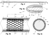
- Fig. 6c shows a radial section (G-G) of the portion 51b of the insulated 53 electrode body 52 provided with the net 58 of biodegradable microfibres enclosed by the matrix layer 56.
- the rigid matrix layer 56 consists of or comprises a biodegradable material it is mandatory that the biodegradation rate of the material(s) forming the matrix layer 56 is substantially higher than that of the material from which the microfibres 58 are formed.
- the proto-microelectrode 62, 63, 64, 66, 68, 70 is provided with a single biodegradable microfibre 68 or a thread 68 of a multitude of biodegradable microfibres disposed on the insulation layer 63 of the microelectrode body 62 in form of a coil 68.
- the coil 68 is fastened on the insulation layer 63 at least at both ends (not shown) but may also be fastened at points intermediate between the ends.
- the electrode body 62 of the rotationally symmetric proto-microelectrode 61 comprises non-insulated distal body portion ending in a tip 64.
Landscapes
- Health & Medical Sciences (AREA)
- Life Sciences & Earth Sciences (AREA)
- Veterinary Medicine (AREA)
- Heart & Thoracic Surgery (AREA)
- Animal Behavior & Ethology (AREA)
- General Health & Medical Sciences (AREA)
- Public Health (AREA)
- Surgery (AREA)
- Vascular Medicine (AREA)
- Epidemiology (AREA)
- Engineering & Computer Science (AREA)
- Biomedical Technology (AREA)
- Radiology & Medical Imaging (AREA)
- Nuclear Medicine, Radiotherapy & Molecular Imaging (AREA)
- Cardiology (AREA)
- Chemical & Material Sciences (AREA)
- Psychology (AREA)
- Neurosurgery (AREA)
- Neurology (AREA)
- Composite Materials (AREA)
- Materials Engineering (AREA)
- Inorganic Chemistry (AREA)
- Physics & Mathematics (AREA)
- Biophysics (AREA)
- Pathology (AREA)
- Medical Informatics (AREA)
- Molecular Biology (AREA)
- Materials For Medical Uses (AREA)
Description
- The present invention relates to a positional stabilization of medical devices implanted into soft tissue by insertion into the tissue or into a channel of gel provided in the tissue. In particular, the present invention relates their positional stabilization immediately upon implantation and during a period of time following upon implantation.
- Implantation of medical devices or such as microelectrodes, optical microfibres, encapsulated electronics, etc. into soft tissue such as nervous or endocrine or any other kind of soft tissue damages the tissue at the implantation site. Devices of this kind are implanted as such or in form of proto-devices which are transformed to devices upon implantation. The severity of damage depends on the shape, size and surface structure of the device or proto-device and on the method of implantation. It is only upon healing of the wound caused by implantation that the medical device becomes positionally stabilized, that is, does not move in respect of the tissue but only with it. Means for long-term anchoring the device in the tissue such as protrusions or openings for ingrowth of tissue don't exert their effect immediately upon implantation of the device or transformation of an implanted proto-device into the device. During their inefficient anchoring period the device can move in the tissue and thereby even delay anchoring.
- A medical device that is not positionally stabilized is prone to move differently from surrounding tissue, irritating the tissue and causing inflammation. This, in turn, delays tissue integration and jeopardizes the positional relationship between the device and particular tissue elements with which it is desired to interact actively or passively.
- Tissue movements compromising positional stabilization of implanted medical devices include respiration, heart beats, bowel and muscle movements.
-
WO 2010/144016A1 discloses medical microelectrodes configured for the delivery of drugs upon the dissolution of a matrix element. Positional stabilization of the microelectrodes ofWO 2010/144016A1 is not dealt with and biodegradable microfibres forming part of the microelectrodes are not disclosed. - It is an object of the present invention to provide medical devices such as microelectrodes and optical microfibres into soft tissue by which the positional stabilization of the implanted device prior to the healing of the wound caused by implantation is improved.
- Further objects of the invention will become apparent from the following summary of the invention, a number of preferred embodiments thereof illustrated in a drawing, and the appended claims.
- The present invention is based on the insight that, for positionally stabilizing a medical device implanted into soft tissue from the start and over a period thereafter, the provision of a temporary stabilization means is called for. The present invention is furthermore based on the insight that such a means should preferably be a temporary one to provide sufficient stabilizing effect during the period required for integration of the implanted device with the tissue, that is, for healing of the wound caused by the implantation or by surgery preceding implantation. Temporary stabilization means of this kind are also advantageous in short-term implantation when the device is not desired to be permanently anchored but is removed from the tissue a short time upon implantation, such as after an hour or a day. In parallel with progressing integration of the device into the tissue the need for anchoring decreases to finally reach a state in which a residual anchoring primarily serves for hindering the device to travel in the tissue. This kind of decrease of an anchoring capability over time facilitates removal of the device if desired, thus reducing the risk of tissue damage during removal.
- More particularly, the present invention is directed to medical devices implanted into soft tissue by insertion, either by the device itself being inserted into soft tissue or by being inserted into a channel in the tissue provided by other means. A feature common to medical devices insertable into soft tissue is their oblong and distally tapering shape. Tissue-insertable devices can also take the form of proto-devices, that is, devices comprising the device to be inserted in combination with insertion promoting means. Such proto-devices, in particular in form of proto-microelectrodes, are well known in the art (
WO 2009/075625 A1 ;WO 2010/144016 A1 ;WO 2012/025596 A2 ). - A useful means for positionally stabilizing a proto-device for implantation of soft tissue according to the invention are biocompatible microfibres attached to the surface of the device and capable of being degraded upon implantation by contact with aqueous body fluid, in particular capable of being degraded and resorbed over a period at least corresponding to the period of time required for positional stabilization of the device by integration into the tissue. Microfibres for use in the invention are preferably degradable by hydrolysis, in particular by enzymatically enhanced hydrolysis. It is particularly preferred for microfibres of the invention to be used in form of non-woven microfibre aggregates. Non-woven microfibre aggregates consist of irregularly intertwined microfibres and may comprise microfibres attached to each other in an irregular manner such as by attachment caused by local melting and/or by gluing with a biocompatible glue.
- The time for positional stabilization by integration may range from a few days, such as 2 or 5 or ten days to a couple of weeks, such as 2 or 5 weeks, and occasionally even a few months. Degradable microfibres of this kind are known in the art, such as microfibres of polylactide and poly(lactide-co-glycolide), polyvinyl acetate and polyvinyl alcohol and their cross-linked modifications, the molecular weight of which can be varied to provide for suitable rates of degradation. Other microfibres for use in the invention are natural and synthetic proteinaceous microfibres, such as fibrin microfibres, collagen microfibres, laminin microfibres, fibronectin microfibres, cross-linked gelatin microfibres, silk microfibres produced from aqueous protein solutions as disclosed by Viney C and Bell F I (Curr Opin Solid State Mater Sci. 8 (2005) 164-169) but also inorganic microfibres such phosphate glass microfibres, for instance P40Na20Ca16Mg24 phosphate glass microfibres disclosed in
US 8182496 B2 . - By their attachment to the surface of the device the biocompatible microfibres increase that surface and make it irregular. The thus increased and irregular surface of the device adheres more easily to the surface of the tissue to which it abuts. Microfibres of the invention are in the micro- or nanometer diameter range. Particularly preferred are electrospun microfibres and electrospinning is a preferred method for producing microfibres of the invention. It is within the ambit of the invention to provide the device with a net of fibrin microfibres by electrospinning fibrinogen, such as by the method of S R Perumcherry et al. disclosed in Tissue Eng Part C Methods 17; (2011) 1121-30 or with a net of poly(lactide-co-glycolide)/fibrin microfibres such as one disclosed by Perumcherry et al. in Tissue Eng Part A 19;7-8(2012) 849-859. A self-assembling fibrin net can also be produced by applying an aqueous solution of fibrinogen and thrombin rich in calcium directly to a microelectrode, then cross-linking the microfibres by applying an aqueous solution of plasma transglutaminase and/or factor XIII on the newly formed net for crosslinking.
- It is preferred for a microfibre to be selected from proteinaceous microfibre and polyester fibre. Preferred fibrous materials include those based on poly(lactide), poly(lactide-co-glycolide), poly(glycolide), electrospun albumin, mucus material rich in glycoprotein. A particularly preferred kind of microfibres are electro-spun microfibres. According to preferred aspect of the invention the microfibres form a non-woven irregular structure. It is preferred for a microfibre to be adhesively attached to a microelectrode and to one or more other microfibres. Preferably the microfibres are disposed along 50 % or more of the axial extension of a microelectrode. Microfibres for use in the invention can be of a resilient or a non-resilient material.
- According to the present invention thus is provided a proto-device for implantation into soft tissue, in particular nervous or endocrine tissue, selected from the group consisting of proto-microelectrode, proto-optical fibre, proto-polymer tube for drug delivery, proto-electrical lead, proto-encapsulated electronics,
- comprising an oblong device body having a proximal end, a distal end, and a central axis,
- comprising biodegradable microfibres adhesively attached to the device body, wherein a microfibre is biodegradable in the tissue within a period of one or two weeks or one month or two months from implantation;
- comprising a rigid matrix of biocompatible material having an outer face and enclosing the device body and the microfibres; wherein the rigid matrix of biocompatible material is dissolvable and/or degradable in aqueous body fluid at a rate superior to the rate of microfibre degradation by a factor of 2 or 5 or 10 or 20 or, in particular, of 100 or more;
- comprising a means for supporting permanent positional stabilization upon biodegradation of the microfibres comprised by the device body or attached to an outer face thereof, wherein the means is selected from the group consisting of: rugged surface of the device body, knobby retainer optionally comprising a rugged surface attached to device body, eye, loop or bent section of the device body, wherein the bending section is bent away from the central axis by an angle of 15 ° or more, in particular by an angle of 30° or more.
- It is preferred that at least 80 %, in particular at least 90 % or 95 % or 99 % or 100 % of the microfibres are biodegradable in the tissue within a period of one or two weeks or one month or two months from implantation.
- Preferred microfibres for use in the invention comprise synthetic polymer fibres such as polylactide fibres, poly(lactide-co-glycolide) fibres, polyglycolide fibres, polyvinyl acetate fibres, polyvinyl alcohol fibres; natural and synthetic proteinaceous fibres, such as albumin fibres, fibrin fibres, collagen fibres, laminin fibres, fibronectin fibres, cross-linked gelatin fibres, silk fibres, glycoprotein fibres; inorganic fibres such as phosphate glass fibres. A biodegradable microfibre can also be a crosslinked, that is, of a crosslinked material.
- According to a first preferred aspect of the invention the microfibres or a portion thereof are dispersed in the rigid matrix, such as at least 50 % or 80 % or 90% or even more than 95 % of the microfibres.
- According to a second preferred aspect of the invention the microfibres are additionally attached adhesively to each other.
- The rigid matrix consists of or comprises preferably one or more members of the group consisting of: low molecular carbohydrate, in particular monosaccharide or disaccharide, proteinaceous material, in particular gelatin.
- According to a third preferred aspect of the invention a majority of the microfibers, such as more than 50 % or more than 80 % of the microfibers, is disposed near the outer face of the rigid matrix that is, at an average distance from the outer face of the device corresponding to their two-fold or five-fold average distance from an outer face of the device.
- It is preferred for the rigid matrix to be disposed rotationally symmetrically or about rotationally symmetrically in respect of a longitudinal axis of the device body.
- According to a third preferred aspect of the invention a glidant layer facilitating insertion into tissue is disposed on the outer face of the rigid matrix. The glidant layer can additionally be capable of delaying access of aqueous body fluid to the rigid matrix during implantation so as to prevent premature its premature dissolution.
- According to a fourth preferred aspect of the invention the proto-device comprises a means for supporting permanent positional stabilization attached to an outer face of the device body, in particular a means for increasing the surface of the device body, such as a rugged or knobby stabilization element. The means for supporting permanent positional stabilization is preferably arranged at a distal portion of the device body, in particular fully or partially surrounds a distal portion thereof.
- Alternatively or additionally, the means for supporting permanent positional stabilization can have the form of an eye or loop formed by the device body and be preferably disposed at a distal portion thereof. They may also have the form of a bent section of the device body with a bending angle of 15° or more. The retainer means can also comprise or consist of a coat of cell adhesion promoting material on the device body such as L1 protein or neural cell adhesion molecule.
- Due to the ingrowth of adjacent tissue, that is, by adjacent tissue closing in on the implanted device, the force needed for positional stabilization of an implanted device of the invention diminishes over time. This allows the device retaining effect of the means for positional stabilization to decrease over time, that is, to be temporal rather than permanent. While a useful rate of decrease of the device retaining effect, that is, the positional stabilizing effect, can vary depending on the kind and properties of the implanted device, a general measure of such decrease will be a reduction by 50 % or more one or two months from implantation, and may even reach 80 % or 90 %.
- According to the present invention is furthermore provided a proto-device for implantation into soft tissue such as nervous tissue in form of a proto-microelectrode comprising an oblong electrically conducting core having a proximal end and a distal end, one or more insulating layers on a portion of the core extending from the proximal end thereof towards the distal end, wherein the fibres are adhesively attached to the insulating layer and/or the core and, optionally, to each other. It is preferred for a diameter of the core or the combination of core and insulating layer(s) to be 100 um or less, in particular 35 um or less, more preferred 15 um or less or even 8 um or less. The diameter of the core or the combination of core and insulating layer(s) can vary in a distal-proximal direction, in particular increase in a distal direction. The core is preferably of metal or comprises metal, in particular a noble metal such as gold, platinum or iridium and their alloys. Alternatively or additionally, the core consists of or comprises electrically conducting polymer and/or electrically conducting carbon such as graphite or graphene. An insulating layer preferably comprises or consists of polymer material, in particular one selected from the group consisting of Parylene, polyurethane, silicone. According to a further preferred aspect of the invention the core is extendable in an axial direction and/or is flexible. The core is preferably in wire or ribbon form. However, any other oblong cores can be used in the invention, such as axially extensible cores of, for instance, meander form, and hollow cores. A suitable electrically conducting polymer core material is poly(3,4-ethylenedioxythiophene (PEDOT). Furthermore, the microelectrode body may comprise electrically conducting carbon such as graphite or graphene, optionally in form of nanotubes. A preferred electrode body insulating material is Parylene. Other preferred electrode body coating materials are polyurethane and silicone but other biocompatible polymer materials may be used as well. Appropriate inorganic materials for electrical insulation such as hafnium oxide can also be used. A preferred method of electrode body coating with insulating material is by vapour phase deposition.
- A microelectrode of the invention can be essentially straight but may alternatively comprise bent portions allowing its extension in an axial (proximal-distal) direction. Preferred are bent portions with a bending angle of 15° or more. Axially extendable electrodes for use in the invention, such as electrodes comprising meander-formed sections, are disclosed in
WO 2009/075625 , which is incorporated herein by reference. - Encapsulated electronics of the invention can, for instance, comprise electronics for electrical stimulation of cells or for recording electrical signals emitted from nerve cells. The use of two or more medical devices for simultaneous implantation and positional stabilization is also comprised by the invention, such as implantation and positional stabilization of bundles and arrays of microelectrodes and/or optical and/or other devices of the invention.
- According to the present invention is additionally provided a method of manufacture of the proto-device of the invention, comprising providing the device; adhesively attaching biocompatible microfibres to a portion of the device and to each other; immerging the combination of device and microfibres into an aqueous solution of a biodegradable proteinaceous or carbohydrate material; drying the combination; optionally covering an outer face of the combination with a material preventing premature dissolution of the rigid matrix during insertion into soft tissue, such as a wax or a triglyceride melting slightly above body temperature. An advantageous modification of the method is to cool the proto-microelectrode prior to insertion to a temperature near 0 °C, such as a temperature between 0° C and 5° C, or to an even lower temperature below 0 °C. It is preferred for the device to be one of: microelectrode, optical fibre, polymer tube for drug delivery, electrical lead, encapsulated electronics; particularly preferred is a device in form of a microelectrode.
- The invention will now be explained in more detail by reference to a number of preferred embodiments illustrated in a drawing, which is not to scale and only intended to illustrate design principles of the devices of the invention.
-
-
Fig. 1 represents a first embodiment of the microelectrode of the invention for use in the invention in an axial section B-B comprising two eyes for tissue ingrowth; -
Fig. 1a is a radial section A-A of the microelectrode ofFig. 1 ; -
Fig. 2 represents a combination of the microelectrode ofFig. 1 and microfibres surrounding and attached to it, in a side view perpendicular to the eyes; -
Fig. 3 . represents a first embodiment of the proto-microelectrode of the invention formed by incorporating the combination of microelectrode and microfibres embedded in a rigid matrix of a material dissolvable in aqueous body fluid, in the same view as inFig. 2 , with the rigid matrix in a transparent presentation. The rigid matrix is shown translucent. -
Fig. 4 represents a second embodiment of the proto-microelectrode of the invention comprising an axially extendable electrode body, in the same view asFig. 3 . -
Fig 4a is a partial enlarged view ofFig. 4 , in the same section. -
Fig. 4b represents a variety of the embodiment ofFigs. 4, 4a , in a partial enlarged view and in the same section. -
Figs. 5, 5a represent an embodiment of a proto-optical fibre of the invention to which microfibres degradable in aqueous body fluid are attached and which is embedded, in combination with said microfibres, in a rigid matrix of a material dissolvable in aqueous body fluid.Fig. 5 is an axial section E-E corresponding to that ofFig. 4 whileFig. 5a is a radial section F-F. -
Figs. 6-6c illustrate a third embodiment of the proto-microelectrode of the invention formed by providing a microelectrode (Figs. 6, 6a ) with a net of biodegradable microfibres enclosing a section of its elongated body (Figs. 6b, 6c , axial section M-M,Fig. 6). Fig. 6b is a side view partial in section of the electrode section covered with the net of biodegradable microfibres of which a radial section (G-G,Fig. 6b ) is shown inFig. 6c in a state embedded in a rigid matrix of a material degradable or dissolvable in aqueous body fluid and with the rigid matrix provided with an outer layer of a material delaying contact of the rigid matrix with aqueous body fluid. -
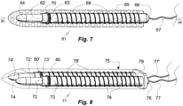
Fig. 7 represents a fourth embodiment of the proto-microelectrode of the invention, in the same view as the partial view ofFig. 6b and with the net of microfibres thereof substituted by a single microfibre spiral wound around the electrode body. The matrix dissolvable in body fluid surrounding the microelectrode is shown translucent. -
Fig. 8 represents a proto-microelectrode bundle of the invention comprising two microelectrodes of the kind shown inFig. 7 and in the same view, surrounded by a common matrix dissolvable in aqueous body fluid; -
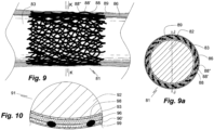
Figs. 9 and 9a represent a variety of net of biodegradable microfibres covering a portion of the insulated body of a proto-microelectrode shown inFigs. 6b, 6c or covering a portion of a proto-optical fibre, the net being layered and extending to from the insulation layer to the outer face of the biodegradable and/or biodegradable matrix layer, in the same section, respectively; -
Fig. 10 represents an enlarged section of a variety of the proto-microelectrode of the ofFigs. 6b, 6c comprising two biodegradable matrix layers, a portion of the fibrous net also being disposed in the outer layer, in the same view as inFig. 6b . -
Figs. 1, 1a illustrate afirst embodiment 1 of a microelectrode of the invention comprising twoeyes 10, 10', adistal eye 10 and a proximal eye 10' separated by a straight intermediate section 2'. From the distal end of thedistal eye 10 extends a straightdistal section 4 ending in a distal tip 4'. From the proximal end of the proximal eye 10' extends a straightproximal section 2" at the proximal end of which aflexible lead 7 is attached bysolder 6. Themicroelectrode 1 is cylindrical in a radial section. It comprises an electrically conductingcore distal section 4 extending from the tip 4' in a proximal direction, by aninsulation layer 5 of a non-conducting material, in particular a non-conducting polymer. The co-planar distal andproximal eyes 10, 10' are designed for long-term positional stabilization by tissue ingrowth. Theeyes 10, 10' can be made by laser milling prior to applying theinsulation layer 5. Theflexible lead 7 provides electrical connection with an electrode control unit (not shown). Alternatively, theflexible lead 7 can be integral with thecore Fig. 1a is a radial section A-A (Fig. 1 ) of the second eye 3'. -
Fig. 2 illustrates acombination 11 themicroelectrode 1 of the invention and an irregular fibrous enclosure formed bysingle microfibres 8 of cross-linked gelatin adhesively attached by electrospinning to the outer face of theelectrode insulation layer 5 at points ofattachment 9 and to each other at points of attachment 9'. The distal,non-insulated section 4 of thecore Fig. 1 ) comprising the distal tip 4' has nomicrofibres 8 attached to it. - The first embodiment of a proto-
microelectrode 21 of the invention shown inFig. 3 has been obtained by enclosing by a mould, preferably a of a gas permeable material, to a depth close to its proximal end the combination ofmicroelectrode 1 andmicrofibre 8, filling the interstice between thecombination rigid matrix layer 12 on themicroelectrode 1 in which themicrofibres 8 are disposed. Then a dissolution retarding and glidingenhancement layer 13 of a triglyceride is applied by spray coating or dip coating to the distal and lateral faces of therigid matrix layer 12 thus formed. - The proto-
microelectrode 21 is rotationally symmetric in respect of its longitudinal axis C-C, which is coincident with the longitudinal axis B-B of themicroelectrode 1.Fig. 3 is a sectional axial view in regard of thematrix layer 12 and the retarding and glidingenhancement layer 13 and a side view in regard of thecombination 11 ofFig. 2 incorporated in thematrix layer 12.Points 9 of microfibre attachment and thesoldering point 6 have been omitted inFig. 3 . -
Fig. 4 illustrates, in a side view, asecond embodiment 31 of the proto-microelectrode of the invention comprising amicroelectrode sections distal terminal section 33 is free of insulation. The central flexible zigzag-formedsection 32 and short straight distal and proximalterminal sections 32', 32" are centred in respect of electrode axis D-D. The zigzag-formedsections 32 include an angle α of about 45° with the axis D-D. -
Fig. 4a is a partial enlarged view of themicroelectrode Fig. 4 , illustrating a bend 38 of thecentral section 32 with theinsulation layer 37 on the electrode body 38 shown. Theinsulation layer 37 covers the entire body 38 of themicroelectrode distal tip 33. The electrode body 38 is about cylindrical in a radial section but may alternatively have any other form in a radial section, which is however not preferred. Aflexible lead 34 attached to the electrode body 38 at the proximal end of the proximal section 32'' by soldering or welding provides electrical connection with an electrode control unit (not shown). A distal portion of thecentral section 32 is surrounded bymicrofibres 35 of cross-linked gelatin, which are adhesively attached to theinsulation 37 and to each other so as to form a layer or fleece or net ofnon-woven 35, also shown in a side view inFig. 4 . Thesecond embodiment 31 of the proto-microelectrode of the invention is obtained in a manner similar to that used to produceembodiment 21 of Example 1. Thematrix layer 36 of glucose comprising a gelling agent such as gelatin is disposed about rotationally symmetric around adistal portion 39 of wave-formedelectrode section 32. Thematrix layer 36 is about rotationally symmetric in respect of the electrode axis D-D and narrows in a distal direction so as to provide the proto-microelectrode 31 with a blunt distal tip. Not shown inFig. 4 is a solder/welding point disposed at the proximal end of the electrode body 38 by which theflexible lead 34 for connecting the electrode body 38 to a control unit is attached to the electrode body 38. -
Fig. 4b is a partial view of a modification of themicroelectrode Fig. 4 , from which it differs only by the geometry ofbends bends -
Figs. 5, 5a illustrate a proto-optical fibre 41 of the invention comprising a centraloptical fibre 42 of glass or a translucent polymer material ending in aflat tip 43 from which radiation conducted by theoptical fibre 42 exits in a distal direction. Theoptical fibre 42 is rotationally symmetric in respect of its central longitudinal axis E-E. Acentral portion 49 of theoptical fibre 42 is surrounded byfilaments 45 of cross-linked gelatin adhesively attached to theoptical fibre 42 and to each other so as to form a layer or fleece ofnon-woven 45. The proto-optical fibre 41 of the invention is obtained in the same manner as thefirst embodiment 21 of the proto-microelectrode of the invention illustrated in Example 1. Thematrix layer 46 of glucose comprising a gelling agent such as gelatin is disposed rotationally symmetric around theoptical fibre 42 axis E-E and narrows in a distal direct so as to provide the proto-optical fibre 41 with a blunt distal tip. At a distal section intermediate between thedistal end 43 of theoptical fibre 42 and theportion 49 of theoptical fibre 42 surrounded bymicrofibres 45 theoptical fibre 42 extends through and adheres to aretainer 47 of a polymer material that is not degradable in aqueous body fluid or the rate of degradation of which is substantially smaller than that of themicrofibres 45. The aim with theretainer 47 is to provide additional positional stabilization upon insertion of the proto-optical fibre 41 into soft tissue and dissolution/degradation of itsmatrix layer 46 and fibrous net 45; for improved tissue adhesion it can be coated with L1 protein or neuralcell adhesion molecule 1 or other another cell adhesion promoting material. The view ofFig. 5 corresponds to that ofFig. 4 . -
Fig. 5a is a radial section F-F through at the proto-optical fibre 41 at theretainer 47 level, also illustrating a dissolution retarding/friction decreasingtriglyceride layer 48 on thematrix 46 omitted inFig. 5 . - The elongated proto microelectrode 51 of
Figs. 6, 6a comprises an electrically conductingelectrode body 52 covered, except for adistal terminal portion 54 thereof, with alayer 53 of insulating polymer material. Theelectrode body 52 and theflexible lead 57 providing electrical contact with an electrode control unit (not shown) are distal and proximal portions of a singlemetallic wire flexible lead portion 57 also being covered with thelayer 53 of insulating polymer material. Near its distal end the insulatinglayer 53 is provided with apolymer sleeve 55 extending around its periphery. Thesleeve 55 has a rugged surface 55' which assists in positionally stabilizing theelectrode 51 in the tissue upon dissolution in aqueous body fluid of amatrix 56 of glucose and gelatin covering the insulated and non-insulated portions of theelectrode body 52 and thesleeve 55.Fig. 6a is an enlarged view of the distalterminal portion 51a of theproto microelectrode 51. -
Fig. 6b shows, in a side view, aninsulated section 51b of theelectrode body 52 disposed proximally of thesleeve 55. Theinsulated section 51b is provided with a net 58 of biodegradable polymer microfibres attached to its surface and extending circumferentially so as to enclose theinsulated section 51b. While theinsulated section 51b provided with the fibrous net 58 is shown in a side view thematrix layer 58 disposed thereon is shown in an axial section (axis F-F,Fig. 6 ) as is theoptional layer 59 of a material delaying contact of therigid matrix 56 layer with aqueous body fluid, for instance a layer of a lipid melting at a temperature slightly above body temperature. -
Fig. 6c shows a radial section (G-G) of theportion 51b of the insulated 53electrode body 52 provided with the net 58 of biodegradable microfibres enclosed by thematrix layer 56. In the event that therigid matrix layer 56 consists of or comprises a biodegradable material it is mandatory that the biodegradation rate of the material(s) forming thematrix layer 56 is substantially higher than that of the material from which themicrofibres 58 are formed. -
Fig. 7 shows a rotationally symmetric (longitudinal axis H-H)elongate microelectrode degradable matrix 65 so as to form aproto microelectrode 61 of the invention. - Instead of the net 58 of biodegradable microfibres of the proto-microelectrode of
Figs. 6b, 6c the proto-microelectrode biodegradable microfibre 68 or athread 68 of a multitude of biodegradable microfibres disposed on theinsulation layer 63 of themicroelectrode body 62 in form of acoil 68. Thecoil 68 is fastened on theinsulation layer 63 at least at both ends (not shown) but may also be fastened at points intermediate between the ends. Theelectrode body 62 of the rotationally symmetric proto-microelectrode 61 comprises non-insulated distal body portion ending in atip 64. At its insulated proximal end 66 a flexible insulatedelectrical lead 67 is attached to the electrode body to provide for electrical connection with a control unit (not shown). Asleeve 70 of polymer material is attached to a frontal portion of theinsulation layer 63 from which it extends in a radial direction. Thesleeve 70 has a rugged surface to provide for enhanced contact with abutting soft tissue to improve positional stability of themicroelectrode biodegradable microfibre 68 preceded by dissolution of thematrix 65 in which themicroelectrode thread 68 is embedded. -
Fig. 8 shows aproto microelectrode bundle 71 comprising afirst microelectrode Fig. 7 mounted at their proximal ends in a through bores of astiff polymer base 79 from which they extend in parallel.Features features Fig. 7 . The proto-microelectrode bundle matrix 75 of a biocompatible water soluble agent, for instance glucose or glucose comprising gelatin. Thematrix 75 can be covered by a thin layer of a dissolution delaying material (not shown inFig. 8 ), such as a triglyceride of a melting point above body temperature. -
Fig. 9 shows a side view andFig. 9a a radial section K-K of an insulated portion of a proto-microelectrode 81 of the invention of oblong cylindrical form covered by three layers of a net ofmicrofibres 88, 88', 88'' which are biodegradable in aqueous body fluid, aninner layer 88, an intermediate layer 88' and an outer layer 88''. Thelayers innermost layer 88 covers and adheres to thepolymer insulation layer 86 covering the electrically conductingelectrode body 82. Thelayers matrix 86 of a biocompatible material which is dissolvable or degradable in aqueous body fluid, such as a matrix of low molecular weight carbohydrate or protein, for instance glucose or gelatin. Thematrix 86 is covered by athin coat 89 of, for instance, a lipid melting above body temperature covering the outer face of thematrix 86 layer to protect it from premature dissolution or degradation by aqueous body fluid. A multi-layered coat of this kind can also be applied to an optical fibre, directly on the fibre, on a light reflecting coat covering the optical fibre or on any other implantable proto device of the invention. - A
variety 91 of the proto-microelectrode ofFigs. 6-6c is illustrated inFig. 10 in a partial sectional view, enlarged; the view ofFig. 10 corresponds about to that ofFig. 6c . The proto-microelectrode 91 differs from that ofFigs 6-6c by the matrix comprising to sections, aninner section 96 and an outer section 96', which can be of same or different material. Upon application of theinner section 96 on theinsulation layer 93 covering the electrically conductingelectrode body 92 theinner section 96 is covered with a net ofmicrofibres 98, which may advantageously be applied when theinner section 96 is not fully dried, that is, is somewhat sticky. Instead of the net of microfibres several layers of the fibrous net 98 or a fibrous fleece may be applied on theinner section 96, which then is covered by a thin outer section 96' of same or different material, in particular of a material of a higher dissolution rate in aqueous body fluid than the material of theinner section 96. The outer section 96' can be covered by alayer 99 of a material delaying access of aqueous body fluid to the outer layer 96' to prevent its premature dissolution during implantation.
Claims (18)
- Proto-device for implantation into soft tissue, in particular nervous or endocrine tissue, selected from the group consisting of proto-microelectrode, proto-optical fibre, proto-polymer tube for drug delivery, proto-electrical lead, proto-encapsulated electronics, comprising an oblong device body (1) having a proximal end, a distal end, and a central axis; characterized in that the proto-device further comprises:(i) biodegradable microfibres (8) adhesively attached to the device body, wherein a microfibre is biodegradable in the tissue within a period of one or two weeks or one month or two months from implantation;(ii) a rigid matrix (12) of biocompatible material having an outer face and enclosing the device body and the microfibres, wherein the rigid matrix of biocompatible material is dissolvable and/or degradable in aqueous body fluid at a rate superior to the rate of microfibre degradation by a factor of 2 or 5 or 10 or 20 or, in particular, 100 or more; and(iii) a means for supporting permanent positional stabilization (10, 10') upon biodegradation of the microfibres comprised by the device body or attached to an outer face thereof, wherein the means is selected from the group consisting of: rugged surface of the device body, knobby retainer optionally comprising a rugged surface attached to device body, eye, loop or bent section of the device body, wherein the bending section is bent away from the central axis by an angle of 15 ° or more, in particular by an angle of 30° or more.
- Proto-device according to claim 1, characterized in that at least 80 %, in particular at least 90 % or 95 % or 99 % or 100 % of the microfibres are biodegradable in the tissue within a period of one or two weeks or one month or two months from implantation.
- Proto-device according to claim 2, characterized in that a biodegradable microfibre is selected from the group consisting of synthetic polymer fibre such as polylactide fibre, poly(lactide-co-glycolide) fibre, polyglycolide fibre, polyvinyl acetate fibre, polyvinyl alcohol fibre; natural and synthetic proteinaceous fibre, such as albumin fibre, fibrin fibre, collagen fibre, laminin fibre, fibronectin fibre, cross-linked gelatin fibre, silk fibre, glycoprotein fibre; inorganic fibre such as phosphate glass fibre; wherein a biodegradable microfibre can be a crosslinked microfibre.
- Proto-device according to claim 2 or 3, characterized in that a microfibre is an electrospun, optionally cross-linked microfibre.
- Proto-device according to any of clams 1 to 4, characterized in that the microfibres or a portion thereof are dispersed in the rigid matrix.
- Proto-device according to any of claims 1 to 5, characterized in that the microfibres are additionally attached adhesively to each other.
- Proto-device according to any of claims 1 to 6, characterized in that the rigid matrix consists of or comprises one or more of the group consisting of low molecular carbohydrate, in particular monosaccharide or disaccharide, proteinaceous material, in particular gelatin.
- Proto-device according to any of claims 1 to 7, characterized in that the rigid matrix is disposed rotationally symmetrically or about rotationally symmetrically in respect of a longitudinal axis of the device body.
- Proto-device according to any of claims 1 to 8 characterized in that a glidant layer (13) is disposed on the outer face of the rigid matrix.
- Proto-device according to claim 9, characterized in that the glidant layer is capable of delaying access of aqueous body fluid to the rigid matrix during implantation.
- Proto-microelectrode according to any of claims 1 to 10, characterized in that the device body is or comprises a microelectrode (1) comprising an electrically conducting core (2, 2'. 2") having a proximal end and a distal end, and one or more insulating layers (5) on a portion of the core extending from the proximal end towards the distal end; wherein the microfibres (8) are adhesively attached (9) to the insulating layer and/or to the core.
- Proto-microelectrode according to claim 11, characterized in that a diameter of the core or the combination of core and insulating layer(s) is 100 µm or less, in particular 35 µm or less, more preferred 15 um or less or even 8 um or less.
- Proto-microelectrode of claim 11 or 12, characterized in that the diameter of the core or the combination of core and insulating layer(s) varies in a distal-proximal direction, in particular increases in a distal direction.
- Proto-microelectrode of any of claims 11 to 13, characterized in that the core is of metal or comprises metal, in particular a noble metal such as gold, platinum or iridium and their alloys.
- Proto-microelectrode of any of claims 11 to 14, characterized in that the core is of or comprises electrically conducting polymer and/or electrically conducting carbon such as graphite or graphene.
- Proto-microelectrode of any of claims 12 to 14, characterized in that an insulating layer comprises or consists of polymer material, in particular one selected from the group consisting of Parylene, polyurethane, silicone.
- Proto-microelectrode of any of claims 11 to 17, characterized in that the core is extendable in an axial direction.
- Method of manufacture of the proto-device of any of clams 1 to 10 and of the proto-microelectrode of any of claims 11 to 17, comprising providing the device; adhesively attaching biocompatible microfibres to a portion of the device and to each other; immerging the combination of device and microfibres into an aqueous solution of a biodegradable proteinaceous or carbohydrate material; drying the combination; optionally covering an outer face of the combination with a material preventing premature dissolution of the rigid matrix during insertion into soft tissue, such as a wax or a triglyceride melting slightly above body temperature.
Applications Claiming Priority (2)
| Application Number | Priority Date | Filing Date | Title |
|---|---|---|---|
| SE1700274 | 2017-11-09 | ||
| PCT/SE2018/000031 WO2019093936A1 (en) | 2017-11-09 | 2018-11-06 | Positional stabilization of tissue-implanted medical devices |
Publications (3)
| Publication Number | Publication Date |
|---|---|
| EP3706858A1 EP3706858A1 (en) | 2020-09-16 |
| EP3706858A4 EP3706858A4 (en) | 2021-08-25 |
| EP3706858B1 true EP3706858B1 (en) | 2024-07-03 |
Family
ID=66438032
Family Applications (1)
| Application Number | Title | Priority Date | Filing Date |
|---|---|---|---|
| EP18877043.2A Active EP3706858B1 (en) | 2017-11-09 | 2018-11-06 | Positional stabilization of tissue-implanted medical devices |
Country Status (5)
| Country | Link |
|---|---|
| US (1) | US11969589B2 (en) |
| EP (1) | EP3706858B1 (en) |
| CN (1) | CN111741790B (en) |
| AU (1) | AU2018366155B2 (en) |
| WO (1) | WO2019093936A1 (en) |
Families Citing this family (3)
| Publication number | Priority date | Publication date | Assignee | Title |
|---|---|---|---|---|
| CN114007686A (en) * | 2019-01-04 | 2022-02-01 | 神经毫微股份公司 | Probe for implanting in nervous tissue comprising a microelectrode or a group of microelectrodes |
| GB2590083A (en) * | 2019-12-04 | 2021-06-23 | Ananda Shakti Tech Ltd | Plasma generator |
| JP2023531516A (en) * | 2020-07-03 | 2023-07-24 | ニューロナノ アーベー | Microelectrodes for insertion into soft tissue |
Family Cites Families (18)
| Publication number | Priority date | Publication date | Assignee | Title |
|---|---|---|---|---|
| US7603179B1 (en) * | 2003-09-16 | 2009-10-13 | Boston Scientific Neuromodulation Corporation | System and method for lead fixation |
| US7949412B1 (en) | 2005-06-02 | 2011-05-24 | Advanced Bionics, Llc | Coated electrode array having uncoated electrode contacts |
| US8639311B2 (en) * | 2005-09-08 | 2014-01-28 | Philadelphia Health & Education Corporation | Sensing probe comprising multiple, spatially separate, sensing sites |
| WO2008048237A2 (en) * | 2005-09-08 | 2008-04-24 | Drexel University | Braided electrodes |
| GB0618787D0 (en) | 2006-09-23 | 2006-11-01 | Univ Nottingham | Degradable composite |
| WO2009067764A1 (en) * | 2007-11-30 | 2009-06-04 | Cochlear Limited | Cochlear implant with improved lumen arrangement |
| ES2408008T3 (en) | 2007-12-10 | 2013-06-17 | Neuronano Ab | Medical electrode, electrode beam and electrode beam assembly |
| CA2764960C (en) * | 2009-06-09 | 2017-07-18 | Neuronano Ab | Microelectrode and multiple microelectrodes |
| AU2014240349B2 (en) * | 2009-06-09 | 2015-11-05 | Neuronano Ab | Microelectrode and multiple microelectrodes comprising means for releasing drugs into the tissue |
| US8751014B2 (en) * | 2010-08-25 | 2014-06-10 | Neuronano Ab | Displacement resistant microelectrode, microelectrode bundle and microelectrode array |
| WO2013025678A1 (en) | 2011-08-16 | 2013-02-21 | Ams Research Corporation | Electrode lead tissue anchor |
| WO2013178229A1 (en) * | 2012-05-30 | 2013-12-05 | Coloplast A/S | A biodegradable non-woven mesh with glue points |
| KR102234778B1 (en) | 2012-06-21 | 2021-03-31 | 뉴로나노 아베 | Medical microelectrode |
| EP3341070B1 (en) | 2014-08-27 | 2019-12-11 | Neuronano AB | Apparatus for implantation of a medical device into neural tissue |
| AU2016308652B2 (en) * | 2015-08-17 | 2021-06-03 | The Johns Hopkins University | Fiber-hydrogel composite surgical meshes for tissue repair |
| US11504524B2 (en) | 2015-09-14 | 2022-11-22 | Drexel University | Multi-site probe and combinatoric method |
| KR102716153B1 (en) * | 2015-11-30 | 2024-10-10 | 뉴로나노 아베 | Anti-hemorrhage microelectrode |
| CN110114112B (en) | 2016-12-05 | 2024-02-09 | 神经毫微股份公司 | Microelectrode array comprising connecting microfibres |
-
2018
- 2018-11-06 US US16/762,531 patent/US11969589B2/en active Active
- 2018-11-06 CN CN201880072462.0A patent/CN111741790B/en active Active
- 2018-11-06 WO PCT/SE2018/000031 patent/WO2019093936A1/en not_active Ceased
- 2018-11-06 EP EP18877043.2A patent/EP3706858B1/en active Active
- 2018-11-06 AU AU2018366155A patent/AU2018366155B2/en active Active
Also Published As
| Publication number | Publication date |
|---|---|
| EP3706858A1 (en) | 2020-09-16 |
| CN111741790A (en) | 2020-10-02 |
| CN111741790B (en) | 2024-06-21 |
| US11969589B2 (en) | 2024-04-30 |
| AU2018366155B2 (en) | 2024-08-01 |
| AU2018366155A1 (en) | 2020-05-14 |
| US20200346002A1 (en) | 2020-11-05 |
| EP3706858A4 (en) | 2021-08-25 |
| WO2019093936A1 (en) | 2019-05-16 |
Similar Documents
| Publication | Publication Date | Title |
|---|---|---|
| EP1324804B1 (en) | Biostable small french lead | |
| US7054692B1 (en) | Fixation device for implantable microdevices | |
| US8244371B2 (en) | Pancreas lead | |
| US8442614B2 (en) | Stiffness enhanced filaments | |
| JP2005522301A (en) | Conductor insulator for implantable medical device and method for manufacturing the same | |
| US11969589B2 (en) | Positional stabilization of tissue-implanted medical devices | |
| EP3548139B1 (en) | Microelectrode array comprising connecting microfibers | |
| US20230277110A1 (en) | Microelectrode for insertion into soft tissue | |
| EP0783901B1 (en) | Electrode system | |
| HK1258580A1 (en) | Haemorrhage avoiding microelectrode | |
| EP0784994A1 (en) | Electrode cable | |
| US20140114384A1 (en) | Implantable fine wire lead for electrostimulation and sensing | |
| EP4259270B1 (en) | Device for insertion of microfilaments in soft tissue | |
| US12484824B2 (en) | Comprising a microelectrode or a set of microelectrodes | |
| WO2002083234A1 (en) | An electrically conductive lead and a method of producing such a lead | |
| US20250064369A1 (en) | Microelectrode for insertion into soft tissue | |
| US20120232370A1 (en) | Implantable Electrode Lead | |
| CN118871166A (en) | Microelectrodes for soft tissue insertion | |
| HK1205969A1 (en) | Medical microelectrode, method for its manufacture, and use thereof |
Legal Events
| Date | Code | Title | Description |
|---|---|---|---|
| STAA | Information on the status of an ep patent application or granted ep patent |
Free format text: STATUS: THE INTERNATIONAL PUBLICATION HAS BEEN MADE |
|
| PUAI | Public reference made under article 153(3) epc to a published international application that has entered the european phase |
Free format text: ORIGINAL CODE: 0009012 |
|
| STAA | Information on the status of an ep patent application or granted ep patent |
Free format text: STATUS: REQUEST FOR EXAMINATION WAS MADE |
|
| 17P | Request for examination filed |
Effective date: 20200423 |
|
| AK | Designated contracting states |
Kind code of ref document: A1 Designated state(s): AL AT BE BG CH CY CZ DE DK EE ES FI FR GB GR HR HU IE IS IT LI LT LU LV MC MK MT NL NO PL PT RO RS SE SI SK SM TR |
|
| AX | Request for extension of the european patent |
Extension state: BA ME |
|
| DAV | Request for validation of the european patent (deleted) | ||
| DAX | Request for extension of the european patent (deleted) | ||
| A4 | Supplementary search report drawn up and despatched |
Effective date: 20210722 |
|
| RIC1 | Information provided on ipc code assigned before grant |
Ipc: A61N 1/05 20060101AFI20210716BHEP Ipc: A61N 1/36 20060101ALI20210716BHEP |
|
| STAA | Information on the status of an ep patent application or granted ep patent |
Free format text: STATUS: EXAMINATION IS IN PROGRESS |
|
| 17Q | First examination report despatched |
Effective date: 20230228 |
|
| RIC1 | Information provided on ipc code assigned before grant |
Ipc: A61N 1/36 20060101ALI20231201BHEP Ipc: A61N 1/05 20060101AFI20231201BHEP |
|
| GRAP | Despatch of communication of intention to grant a patent |
Free format text: ORIGINAL CODE: EPIDOSNIGR1 |
|
| STAA | Information on the status of an ep patent application or granted ep patent |
Free format text: STATUS: GRANT OF PATENT IS INTENDED |
|
| INTG | Intention to grant announced |
Effective date: 20240202 |
|
| GRAS | Grant fee paid |
Free format text: ORIGINAL CODE: EPIDOSNIGR3 |
|
| GRAA | (expected) grant |
Free format text: ORIGINAL CODE: 0009210 |
|
| STAA | Information on the status of an ep patent application or granted ep patent |
Free format text: STATUS: THE PATENT HAS BEEN GRANTED |
|
| AK | Designated contracting states |
Kind code of ref document: B1 Designated state(s): AL AT BE BG CH CY CZ DE DK EE ES FI FR GB GR HR HU IE IS IT LI LT LU LV MC MK MT NL NO PL PT RO RS SE SI SK SM TR |
|
| REG | Reference to a national code |
Ref country code: CH Ref legal event code: EP |
|
| REG | Reference to a national code |
Ref country code: DE Ref legal event code: R096 Ref document number: 602018071419 Country of ref document: DE |
|
| P01 | Opt-out of the competence of the unified patent court (upc) registered |
Free format text: CASE NUMBER: APP_48528/2024 Effective date: 20240826 |
|
| REG | Reference to a national code |
Ref country code: NL Ref legal event code: FP |
|
| REG | Reference to a national code |
Ref country code: LT Ref legal event code: MG9D |
|
| PG25 | Lapsed in a contracting state [announced via postgrant information from national office to epo] |
Ref country code: PT Free format text: LAPSE BECAUSE OF FAILURE TO SUBMIT A TRANSLATION OF THE DESCRIPTION OR TO PAY THE FEE WITHIN THE PRESCRIBED TIME-LIMIT Effective date: 20241104 |
|
| REG | Reference to a national code |
Ref country code: AT Ref legal event code: MK05 Ref document number: 1699177 Country of ref document: AT Kind code of ref document: T Effective date: 20240703 |
|
| PG25 | Lapsed in a contracting state [announced via postgrant information from national office to epo] |
Ref country code: PT Free format text: LAPSE BECAUSE OF FAILURE TO SUBMIT A TRANSLATION OF THE DESCRIPTION OR TO PAY THE FEE WITHIN THE PRESCRIBED TIME-LIMIT Effective date: 20241104 |
|
| PG25 | Lapsed in a contracting state [announced via postgrant information from national office to epo] |
Ref country code: NO Free format text: LAPSE BECAUSE OF FAILURE TO SUBMIT A TRANSLATION OF THE DESCRIPTION OR TO PAY THE FEE WITHIN THE PRESCRIBED TIME-LIMIT Effective date: 20241003 |
|
| PG25 | Lapsed in a contracting state [announced via postgrant information from national office to epo] |
Ref country code: GR Free format text: LAPSE BECAUSE OF FAILURE TO SUBMIT A TRANSLATION OF THE DESCRIPTION OR TO PAY THE FEE WITHIN THE PRESCRIBED TIME-LIMIT Effective date: 20241004 Ref country code: FI Free format text: LAPSE BECAUSE OF FAILURE TO SUBMIT A TRANSLATION OF THE DESCRIPTION OR TO PAY THE FEE WITHIN THE PRESCRIBED TIME-LIMIT Effective date: 20240703 Ref country code: PL Free format text: LAPSE BECAUSE OF FAILURE TO SUBMIT A TRANSLATION OF THE DESCRIPTION OR TO PAY THE FEE WITHIN THE PRESCRIBED TIME-LIMIT Effective date: 20240703 |
|
| PG25 | Lapsed in a contracting state [announced via postgrant information from national office to epo] |
Ref country code: BG Free format text: LAPSE BECAUSE OF FAILURE TO SUBMIT A TRANSLATION OF THE DESCRIPTION OR TO PAY THE FEE WITHIN THE PRESCRIBED TIME-LIMIT Effective date: 20240703 |
|
| PG25 | Lapsed in a contracting state [announced via postgrant information from national office to epo] |
Ref country code: LV Free format text: LAPSE BECAUSE OF FAILURE TO SUBMIT A TRANSLATION OF THE DESCRIPTION OR TO PAY THE FEE WITHIN THE PRESCRIBED TIME-LIMIT Effective date: 20240703 |
|
| PG25 | Lapsed in a contracting state [announced via postgrant information from national office to epo] |
Ref country code: IS Free format text: LAPSE BECAUSE OF FAILURE TO SUBMIT A TRANSLATION OF THE DESCRIPTION OR TO PAY THE FEE WITHIN THE PRESCRIBED TIME-LIMIT Effective date: 20241103 Ref country code: AT Free format text: LAPSE BECAUSE OF FAILURE TO SUBMIT A TRANSLATION OF THE DESCRIPTION OR TO PAY THE FEE WITHIN THE PRESCRIBED TIME-LIMIT Effective date: 20240703 |
|
| PG25 | Lapsed in a contracting state [announced via postgrant information from national office to epo] |
Ref country code: CZ Free format text: LAPSE BECAUSE OF FAILURE TO SUBMIT A TRANSLATION OF THE DESCRIPTION OR TO PAY THE FEE WITHIN THE PRESCRIBED TIME-LIMIT Effective date: 20240703 Ref country code: HR Free format text: LAPSE BECAUSE OF FAILURE TO SUBMIT A TRANSLATION OF THE DESCRIPTION OR TO PAY THE FEE WITHIN THE PRESCRIBED TIME-LIMIT Effective date: 20240703 |
|
| PG25 | Lapsed in a contracting state [announced via postgrant information from national office to epo] |
Ref country code: ES Free format text: LAPSE BECAUSE OF FAILURE TO SUBMIT A TRANSLATION OF THE DESCRIPTION OR TO PAY THE FEE WITHIN THE PRESCRIBED TIME-LIMIT Effective date: 20240703 Ref country code: RS Free format text: LAPSE BECAUSE OF FAILURE TO SUBMIT A TRANSLATION OF THE DESCRIPTION OR TO PAY THE FEE WITHIN THE PRESCRIBED TIME-LIMIT Effective date: 20241003 |
|
| PG25 | Lapsed in a contracting state [announced via postgrant information from national office to epo] |
Ref country code: RS Free format text: LAPSE BECAUSE OF FAILURE TO SUBMIT A TRANSLATION OF THE DESCRIPTION OR TO PAY THE FEE WITHIN THE PRESCRIBED TIME-LIMIT Effective date: 20241003 Ref country code: PL Free format text: LAPSE BECAUSE OF FAILURE TO SUBMIT A TRANSLATION OF THE DESCRIPTION OR TO PAY THE FEE WITHIN THE PRESCRIBED TIME-LIMIT Effective date: 20240703 Ref country code: NO Free format text: LAPSE BECAUSE OF FAILURE TO SUBMIT A TRANSLATION OF THE DESCRIPTION OR TO PAY THE FEE WITHIN THE PRESCRIBED TIME-LIMIT Effective date: 20241003 Ref country code: LV Free format text: LAPSE BECAUSE OF FAILURE TO SUBMIT A TRANSLATION OF THE DESCRIPTION OR TO PAY THE FEE WITHIN THE PRESCRIBED TIME-LIMIT Effective date: 20240703 Ref country code: IS Free format text: LAPSE BECAUSE OF FAILURE TO SUBMIT A TRANSLATION OF THE DESCRIPTION OR TO PAY THE FEE WITHIN THE PRESCRIBED TIME-LIMIT Effective date: 20241103 Ref country code: HR Free format text: LAPSE BECAUSE OF FAILURE TO SUBMIT A TRANSLATION OF THE DESCRIPTION OR TO PAY THE FEE WITHIN THE PRESCRIBED TIME-LIMIT Effective date: 20240703 Ref country code: GR Free format text: LAPSE BECAUSE OF FAILURE TO SUBMIT A TRANSLATION OF THE DESCRIPTION OR TO PAY THE FEE WITHIN THE PRESCRIBED TIME-LIMIT Effective date: 20241004 Ref country code: FI Free format text: LAPSE BECAUSE OF FAILURE TO SUBMIT A TRANSLATION OF THE DESCRIPTION OR TO PAY THE FEE WITHIN THE PRESCRIBED TIME-LIMIT Effective date: 20240703 Ref country code: ES Free format text: LAPSE BECAUSE OF FAILURE TO SUBMIT A TRANSLATION OF THE DESCRIPTION OR TO PAY THE FEE WITHIN THE PRESCRIBED TIME-LIMIT Effective date: 20240703 Ref country code: CZ Free format text: LAPSE BECAUSE OF FAILURE TO SUBMIT A TRANSLATION OF THE DESCRIPTION OR TO PAY THE FEE WITHIN THE PRESCRIBED TIME-LIMIT Effective date: 20240703 Ref country code: BG Free format text: LAPSE BECAUSE OF FAILURE TO SUBMIT A TRANSLATION OF THE DESCRIPTION OR TO PAY THE FEE WITHIN THE PRESCRIBED TIME-LIMIT Effective date: 20240703 Ref country code: AT Free format text: LAPSE BECAUSE OF FAILURE TO SUBMIT A TRANSLATION OF THE DESCRIPTION OR TO PAY THE FEE WITHIN THE PRESCRIBED TIME-LIMIT Effective date: 20240703 |
|
| REG | Reference to a national code |
Ref country code: DE Ref legal event code: R097 Ref document number: 602018071419 Country of ref document: DE |
|
| PG25 | Lapsed in a contracting state [announced via postgrant information from national office to epo] |
Ref country code: SM Free format text: LAPSE BECAUSE OF FAILURE TO SUBMIT A TRANSLATION OF THE DESCRIPTION OR TO PAY THE FEE WITHIN THE PRESCRIBED TIME-LIMIT Effective date: 20240703 Ref country code: RO Free format text: LAPSE BECAUSE OF FAILURE TO SUBMIT A TRANSLATION OF THE DESCRIPTION OR TO PAY THE FEE WITHIN THE PRESCRIBED TIME-LIMIT Effective date: 20240703 Ref country code: DK Free format text: LAPSE BECAUSE OF FAILURE TO SUBMIT A TRANSLATION OF THE DESCRIPTION OR TO PAY THE FEE WITHIN THE PRESCRIBED TIME-LIMIT Effective date: 20240703 |
|
| PG25 | Lapsed in a contracting state [announced via postgrant information from national office to epo] |
Ref country code: EE Free format text: LAPSE BECAUSE OF FAILURE TO SUBMIT A TRANSLATION OF THE DESCRIPTION OR TO PAY THE FEE WITHIN THE PRESCRIBED TIME-LIMIT Effective date: 20240703 |
|
| PG25 | Lapsed in a contracting state [announced via postgrant information from national office to epo] |
Ref country code: IT Free format text: LAPSE BECAUSE OF FAILURE TO SUBMIT A TRANSLATION OF THE DESCRIPTION OR TO PAY THE FEE WITHIN THE PRESCRIBED TIME-LIMIT Effective date: 20240703 Ref country code: SK Free format text: LAPSE BECAUSE OF FAILURE TO SUBMIT A TRANSLATION OF THE DESCRIPTION OR TO PAY THE FEE WITHIN THE PRESCRIBED TIME-LIMIT Effective date: 20240703 |
|
| PLBE | No opposition filed within time limit |
Free format text: ORIGINAL CODE: 0009261 |
|
| STAA | Information on the status of an ep patent application or granted ep patent |
Free format text: STATUS: NO OPPOSITION FILED WITHIN TIME LIMIT |
|
| 26N | No opposition filed |
Effective date: 20250404 |
|
| PG25 | Lapsed in a contracting state [announced via postgrant information from national office to epo] |
Ref country code: MC Free format text: LAPSE BECAUSE OF FAILURE TO SUBMIT A TRANSLATION OF THE DESCRIPTION OR TO PAY THE FEE WITHIN THE PRESCRIBED TIME-LIMIT Effective date: 20240703 |
|
| PG25 | Lapsed in a contracting state [announced via postgrant information from national office to epo] |
Ref country code: LU Free format text: LAPSE BECAUSE OF NON-PAYMENT OF DUE FEES Effective date: 20241106 |
|
| REG | Reference to a national code |
Ref country code: BE Ref legal event code: MM Effective date: 20241130 |
|
| PG25 | Lapsed in a contracting state [announced via postgrant information from national office to epo] |
Ref country code: SE Free format text: LAPSE BECAUSE OF FAILURE TO SUBMIT A TRANSLATION OF THE DESCRIPTION OR TO PAY THE FEE WITHIN THE PRESCRIBED TIME-LIMIT Effective date: 20240703 |
|
| PG25 | Lapsed in a contracting state [announced via postgrant information from national office to epo] |
Ref country code: BE Free format text: LAPSE BECAUSE OF NON-PAYMENT OF DUE FEES Effective date: 20241130 |
|
| PG25 | Lapsed in a contracting state [announced via postgrant information from national office to epo] |
Ref country code: IE Free format text: LAPSE BECAUSE OF NON-PAYMENT OF DUE FEES Effective date: 20241106 |
|
| REG | Reference to a national code |
Ref country code: CH Ref legal event code: U11 Free format text: ST27 STATUS EVENT CODE: U-0-0-U10-U11 (AS PROVIDED BY THE NATIONAL OFFICE) Effective date: 20251201 |
|
| PGFP | Annual fee paid to national office [announced via postgrant information from national office to epo] |
Ref country code: NL Payment date: 20251119 Year of fee payment: 8 |
|
| PGFP | Annual fee paid to national office [announced via postgrant information from national office to epo] |
Ref country code: DE Payment date: 20251029 Year of fee payment: 8 |
|
| PGFP | Annual fee paid to national office [announced via postgrant information from national office to epo] |
Ref country code: GB Payment date: 20251130 Year of fee payment: 8 |
|
| PGFP | Annual fee paid to national office [announced via postgrant information from national office to epo] |
Ref country code: FR Payment date: 20251130 Year of fee payment: 8 |
|
| PGFP | Annual fee paid to national office [announced via postgrant information from national office to epo] |
Ref country code: CH Payment date: 20251201 Year of fee payment: 8 |
|
| PG25 | Lapsed in a contracting state [announced via postgrant information from national office to epo] |
Ref country code: HU Free format text: LAPSE BECAUSE OF FAILURE TO SUBMIT A TRANSLATION OF THE DESCRIPTION OR TO PAY THE FEE WITHIN THE PRESCRIBED TIME-LIMIT; INVALID AB INITIO Effective date: 20181106 |
|
| PG25 | Lapsed in a contracting state [announced via postgrant information from national office to epo] |
Ref country code: CY Free format text: LAPSE BECAUSE OF FAILURE TO SUBMIT A TRANSLATION OF THE DESCRIPTION OR TO PAY THE FEE WITHIN THE PRESCRIBED TIME-LIMIT; INVALID AB INITIO Effective date: 20181106 |