EP3706476A1 - Battery powered device for communicating with an access point device of a communication network - Google Patents
Battery powered device for communicating with an access point device of a communication network Download PDFInfo
- Publication number
- EP3706476A1 EP3706476A1 EP19161268.8A EP19161268A EP3706476A1 EP 3706476 A1 EP3706476 A1 EP 3706476A1 EP 19161268 A EP19161268 A EP 19161268A EP 3706476 A1 EP3706476 A1 EP 3706476A1
- Authority
- EP
- European Patent Office
- Prior art keywords
- communication unit
- access point
- processing unit
- communication
- signal
- Prior art date
- Legal status (The legal status is an assumption and is not a legal conclusion. Google has not performed a legal analysis and makes no representation as to the accuracy of the status listed.)
- Withdrawn
Links
- 238000004891 communication Methods 0.000 title claims abstract description 323
- 238000012545 processing Methods 0.000 claims abstract description 147
- 238000000034 method Methods 0.000 claims description 16
- 238000004590 computer program Methods 0.000 claims description 8
- 238000010586 diagram Methods 0.000 description 5
- 230000001413 cellular effect Effects 0.000 description 1
- 238000005516 engineering process Methods 0.000 description 1
- 239000012530 fluid Substances 0.000 description 1
- 238000005259 measurement Methods 0.000 description 1
- 238000009420 retrofitting Methods 0.000 description 1
Images


Classifications
-
- H—ELECTRICITY
- H04—ELECTRIC COMMUNICATION TECHNIQUE
- H04W—WIRELESS COMMUNICATION NETWORKS
- H04W52/00—Power management, e.g. Transmission Power Control [TPC] or power classes
- H04W52/02—Power saving arrangements
- H04W52/0209—Power saving arrangements in terminal devices
- H04W52/0225—Power saving arrangements in terminal devices using monitoring of external events, e.g. the presence of a signal
- H04W52/0241—Power saving arrangements in terminal devices using monitoring of external events, e.g. the presence of a signal where no transmission is received, e.g. out of range of the transmitter
-
- H—ELECTRICITY
- H04—ELECTRIC COMMUNICATION TECHNIQUE
- H04W—WIRELESS COMMUNICATION NETWORKS
- H04W52/00—Power management, e.g. Transmission Power Control [TPC] or power classes
- H04W52/02—Power saving arrangements
- H04W52/0209—Power saving arrangements in terminal devices
- H04W52/0261—Power saving arrangements in terminal devices managing power supply demand, e.g. depending on battery level
- H04W52/0274—Power saving arrangements in terminal devices managing power supply demand, e.g. depending on battery level by switching on or off the equipment or parts thereof
- H04W52/028—Power saving arrangements in terminal devices managing power supply demand, e.g. depending on battery level by switching on or off the equipment or parts thereof switching on or off only a part of the equipment circuit blocks
-
- Y—GENERAL TAGGING OF NEW TECHNOLOGICAL DEVELOPMENTS; GENERAL TAGGING OF CROSS-SECTIONAL TECHNOLOGIES SPANNING OVER SEVERAL SECTIONS OF THE IPC; TECHNICAL SUBJECTS COVERED BY FORMER USPC CROSS-REFERENCE ART COLLECTIONS [XRACs] AND DIGESTS
- Y02—TECHNOLOGIES OR APPLICATIONS FOR MITIGATION OR ADAPTATION AGAINST CLIMATE CHANGE
- Y02D—CLIMATE CHANGE MITIGATION TECHNOLOGIES IN INFORMATION AND COMMUNICATION TECHNOLOGIES [ICT], I.E. INFORMATION AND COMMUNICATION TECHNOLOGIES AIMING AT THE REDUCTION OF THEIR OWN ENERGY USE
- Y02D30/00—Reducing energy consumption in communication networks
- Y02D30/70—Reducing energy consumption in communication networks in wireless communication networks
Definitions
- the communication between devices is useful for interacting with those devices and for data exchange purposes.
- the internet of things extends the internet connectivity to those devices if they comprise any connectivity, which allows those devices to connect, interact and exchange data.
- the narrowband internet of things (NB-loT) technology can be used in areas beyond the radio coverage of current cellular standards and in devices, which must run from battery power for many years.
- the invention provides a device, which controls the connection attempts for establishing a connection to the communication network.
- the connection attempt may comprise the request of the communication unit for a registration by the access point device.
- the connection between the communication unit and the access point device may be a wireless connection. If the communication unit loses the registration but still being connected or the connection including the registration to the access point device is lost, the processing unit orders the communication unit to stop the communication with the access point device, i.e. to stop any further attempts for establishing a communication with the access point device. Furthermore, the processing unit orders the communication unit to enter the low power mode. The power consumption of the communication unit is less in the low power mode than in the active mode. After stopping the communication with the communication network, the processing unit waits a predetermined period, i.e. the waiting period.
- the processing unit orders to the communication unit to enter the active mode. Furthermore, the processing unit orders the communication unit to try to get a registration and/or to establish a connection to the access point device.
- the device instead of continuously trying to get a registration or to establish a connection with the access point device after a loss of the connection, the device ceases the attempts and waits a predetermined waiting period before trying to get a registration and/or to establish a connection to the communication network, again. Due to the predetermined waiting period, the communication unit stops communication with the communication network for a period, which may cause the access point device to categorize the communication unit as new device.
- the communication unit may be an Internet of Things that is connected to the network.
- the communication unit may further be a narrowband communication unit, which may connect to the Internet of Things.
- the predefined waiting period may be 60 min., preferably 12 h, further preferably 24 h.
- the access point device will categorize the communication unit as a new device.
- the access point device usually provide new devices a higher priority for registration and establishing a connection than known devices. This will further reduce the number of attempts of the communication unit for successfully establishing a connection and registration with the access point device.
- the predefined waiting period is based on a power consumption of the device.
- the waiting period may therefore be adapted to the power consumption of the device. If the remaining battery power is high, the waiting period may be short and the communication unit may carry out several registration/connection attempts. If the remaining battery power is low, the waiting period may be long. Thus, the processing unit controls the communication unit such to perform just a few attempts. In particular, in case of a low remaining battery power, power may be saved. This increases the battery lifetime, further.
- the detachment period i.e. the period in which the communication unit stops any communication with the access point or is detached from the access point device is increased by the waiting period.
- the processing unit may increase the waiting period if the detachment period is short. Thus, using the increase of the waiting period, the processing unit may ensure that the communication unit stops any communication or is detached from the access point device for a minimum period.
- the minimum period may ensure that the access point device grants the communication unit a high priority for getting a registration or for establishing a connection after the attach signal. This will further increase the battery lifetime due to reduced power consumption.
- the predefined waiting period increases if the power consumption of the device increases.
- the increase of the predefined waiting period avoids that the registration/connection attempts of the communication unit will drain battery power when the power consumption of the device is increasing. This may ensure that enough battery power remains for the power consumption of the device, which will increase the lifetime of the battery, further.
- a SIM may connect to a cell tower of a communication network.
- the device may therefore use an already existing wireless network structure to connect to the Internet of Things. This simplifies the use of the device and avoids establishing a new communication network.
- an utility device for connecting to the access point of the network.
- the utility device comprises: a device according to the above description; and an antenna for communicating with an access point of a network; wherein the communication unit is connected to the antenna; and wherein the communication unit is configured to provide and receive communication signals via the antenna.
- the utility device further comprises a main board comprising a main board communication interface and a main processing unit; and a module board comprising a module board communication interface being connected to the main board communication interface; wherein the device and the antenna are arranged on the module board; wherein the processing unit is connected to the module board communication interface; wherein the processing unit is configured to provide and receive control signals via the module board communication interface; wherein the main processing unit is connected to the main board communication interface, and wherein the main processing unit is configured to provide and receive control signals via the main board communication interface.
- the utility device may therefore be retrofitted with the device by connecting the module board comprising the device for communicating with an access point device of a communication network to the utility device.
- This allows retrofitting already existing utility devices if the main board of the utility device comprises a main board communication interface. Furthermore, this simplifies the upgrade or change of the used communication network or access point device since this requires just a replacement of the module board with the respective hardware.
- the communication unit 10 is configured to establish and maintain a connection with the access point device 34 of the communication network 36 shown in figure 1 . Establishing a connection includes the step of getting a registration that is needed to start a communication.
- the communication unit 12 may use a wireless communication channel with the access point device 34. Furthermore, the communication unit 12 may be configured to receive signals from and transmit signals to the processing unit 14, which controls the communication unit 12.
- the communication unit 12 comprises an active mode in which the communication unit 12 may establish a connection to the access point device 34 and communicate with the access point device 34. Furthermore, the communication unit 12 comprises at least a low power mode. In the low power mode, the communication unit 12 uses less power than in the active mode. Furthermore, the communication unit 12 will not carry out any communication, registration or connection attempts in the low power mode.
- the communication unit 12 is configured to repetitively carry out registration and/or connection attempts to register at an access point device 34 of the communication network 36 upon reception of the attach signal. After a timeout period, the processing unit 14 is configured to check whether the communication unit 12 successfully established a connection and registration to the access point device 34. Furthermore, the processing unit 14 may be configured to check whether the communication unit 12 has sent the message within the timeout period.
- the processing unit 14 may adapt the predetermined waiting period 54 based on the detachment period of the communication unit 12.
- a short detachment period may cause the processing unit 14 to increase the predetermined waiting period 54.
- a long detachment period may cause the processing unit 14 to decrease the predetermined waiting period 54.
- the processing unit 14 may increase the predetermined waiting period 54 based on the number of consecutive check results indicating unsuccessful connection attempts. For example, a high number of unsuccessful connection attempts may cause the processing unit 14 to increase the predetermined waiting period 54.
- the housing comprises a PCB being a main board 22.
- the main board 22 comprises the processing unit 14, which may be a micro processing unit for controlling the utility device 16.
- the main board 22 comprises the communication unit 12 and an antenna 24 for wireless communication.
- the communication unit 12 comprises an electrical connection to the antenna and to the micro processing unit.
- the communication unit 12 and the processing unit 14 form the device 10.
- the lower housing element 18 may be connected to the upper housing element 20 to form a casing for the main board 22.
- the upper housing element 20 may comprise a display for displaying the sensor data and/or e.g. status information about the utility device 16.
- the main board 22 may comprise further components, e.g. for controlling the utility device 16, for retrieving the sensor data and for providing communication channels between the components of the utility device 16.
- the communication unit provides a lost registration signal if the communication unit cannot establish a connection to the access point device.
- the lost registration signal indicates that the communication unit is not registered at the access point device, i.e. that the communication unit cannot communicate with the access point device and the communication network.
- the processing unit provides a low power mode signal.
- the communication unit receives the low power mode signal.
- the low power mode signal orders the communication unit to change from the active mode to the low power mode to save power.
- a step 112 after providing the attach signal, the processing unit checks whether the communication unit successfully established a connection to the access point device after a timeout period.
- the processing unit may provide a send message signal according to step 114.
- the send message signal orders the communication unit to send a message being provided by the processing unit.
- the processing unit If the check result indicates, that the communication unit did not establish a connection to the access point device within the timeout period, the processing unit provides a release signal according to step 116. Furthermore, the processing unit provides a low power mode signal to the communication unit according to step 118.
Landscapes
- Engineering & Computer Science (AREA)
- Computer Networks & Wireless Communication (AREA)
- Signal Processing (AREA)
- Mobile Radio Communication Systems (AREA)
Abstract
Description
- The invention relates to a battery powered device for communicating with an access point device of a communication network, an utility device for connecting to the access point of the network, a module board for connecting to a main board of a utility device, a method for establishing a connection between a device for communicating with an access point device of a communication network and an access point device of a communication network.
- The communication between devices, which do not comprise a standard internet connection, is useful for interacting with those devices and for data exchange purposes. The internet of things extends the internet connectivity to those devices if they comprise any connectivity, which allows those devices to connect, interact and exchange data. Particularly, the narrowband internet of things (NB-loT) technology can be used in areas beyond the radio coverage of current cellular standards and in devices, which must run from battery power for many years.
- The user device comprises a customer application which performs the network registration using e.g. AT command parsers. The so called +CEREG command may then be used for network registration status of a user device. The registration may be performed manually or automatically. The automatic registration may be defined as standard to try to connect the device to the network automatically.
- The devices will generally send small amounts of data infrequently. A usage scenario might be 100 to 200 bytes sent twice per day for battery-powered devices. If the connection between the battery-powered device and the network is lost, the battery-powered device tries to reconnect to the network until the connection between the battery-powered device and the network is re-established.
- An object of the invention may be to provide a device having an improved battery power consumption.
-
Claims 1, 9, and 11 to 14 indicate the main features of the invention. Features of embodiments of the invention are subject of claims 2 to 8 and 10. - An aspect of the invention provides a device for communicating with an access point device of a communication network. The device comprises a communication unit for communicating with the access point device; and a processing unit for controlling the communication unit; wherein the communication unit comprises an active mode and a low power mode; wherein the communication unit is further configured to provide a lost registration signal indicating that the communication unit is not registered at the access point device; wherein the processing unit is configured to receive the lost registration signal; wherein, upon reception of the lost registration signal, the processing unit is further configured to provide a release signal to the communication unit, wherein the release signal forces the communication unit to clear at least the registration, in particular to release registration and connection, from the access point device; wherein, upon reception of the lost registration signal, the processing unit is further configured to provide a low power mode signal, wherein the low power signal transfers the communication unit into the low power mode, wherein the processing unit is further configured to provide an attach signal to the communication unit after a predefined waiting period, wherein the attach signal transfers the communication unit to the active mode and which orders the communication unit to start communication with the access point device.
- The invention provides a device, which controls the connection attempts for establishing a connection to the communication network. The connection attempt may comprise the request of the communication unit for a registration by the access point device. The connection between the communication unit and the access point device may be a wireless connection. If the communication unit loses the registration but still being connected or the connection including the registration to the access point device is lost, the processing unit orders the communication unit to stop the communication with the access point device, i.e. to stop any further attempts for establishing a communication with the access point device. Furthermore, the processing unit orders the communication unit to enter the low power mode. The power consumption of the communication unit is less in the low power mode than in the active mode. After stopping the communication with the communication network, the processing unit waits a predetermined period, i.e. the waiting period. After that waiting period, the processing unit orders to the communication unit to enter the active mode. Furthermore, the processing unit orders the communication unit to try to get a registration and/or to establish a connection to the access point device. Hence, instead of continuously trying to get a registration or to establish a connection with the access point device after a loss of the connection, the device ceases the attempts and waits a predetermined waiting period before trying to get a registration and/or to establish a connection to the communication network, again. Due to the predetermined waiting period, the communication unit stops communication with the communication network for a period, which may cause the access point device to categorize the communication unit as new device. The access point device will therefore grant the communication unit a higher priority for receiving a registration and/or for establishing a connection than if the communication unit was detached from the communication network for just a short period. Thus, after the waiting time the communication unit will require a smaller number of registration/connection attempts than without the waiting time. Since each attempt consumes a certain amount of battery power, the communication unit will consume less battery power than without the waiting time. Over the lifetime of the device, this will significantly increase the lifetime of the battery.
- In an example, the access point device is a cell tower of communication network like a NB-IoT-network. The communication unit may then be able to connect to the network.
- Furthermore, the communication unit may be an Internet of Things that is connected to the network. The communication unit may further be a narrowband communication unit, which may connect to the Internet of Things.
- The predefined waiting period may be 60 min., preferably 12 h, further preferably 24 h. After that predefined waiting period, the access point device will categorize the communication unit as a new device. The access point device usually provide new devices a higher priority for registration and establishing a connection than known devices. This will further reduce the number of attempts of the communication unit for successfully establishing a connection and registration with the access point device.
- In an example, after a predefined timeout period, the processing unit is further configured to check whether the communication unit established a registration and connection to the access point device after receiving the attach signal, and, if a check result indicates that the communication unit is not registered or connected to the access point device, to provide the release signal and the low power mode signal to the communication unit.
- Thus, after the predefined waiting period, the processing unit provides the communication unit a predefined timeout period for receiving a registration and/or establishing a connection with the access point device. If the communication unit is unable to get a registration or to establish a connection to the access point device within the timeout period, the processing unit will order the communication unit to cease any further connection attempts until instructed otherwise, i.e. to release from the access point device. Furthermore, the processing unit sends the communication unit to the low power mode to save battery power. After the predefined waiting period, the processing unit may provide the attach signal, again. This avoids a high number of unsuccessful connection attempts after the waiting period if for example the access point device is unavailable. This further reduces the number of registration/connection attempts of the communication unit. Hence, the consumption of battery power may be reduced.
- In an example, the processing unit is further configured to increase the predefined waiting period based on a number of how many consecutive check results indicate that the communication unit is not registered or connected to the access point device.
- The waiting period for starting a new registration or connection attempt becomes longer depending on the number of attempts that were cancelled due to exceeding the timeout period. If many consecutive registration/connection attempts fail, the communication unit carries out further attempts after a longer waiting period. The longer waiting period will improve the priority of the device at the access point device for getting a registration and/or establishing a connection. This will reduce the number of attempts for establishing a working communication connection between the communication unit and the access point device. Furthermore, this will further reduce the consumption of battery power such that the battery lifetime is further increased.
- In an example, the predefined waiting period is based on a power consumption of the device.
- The waiting period may therefore be adapted to the power consumption of the device. If the remaining battery power is high, the waiting period may be short and the communication unit may carry out several registration/connection attempts. If the remaining battery power is low, the waiting period may be long. Thus, the processing unit controls the communication unit such to perform just a few attempts. In particular, in case of a low remaining battery power, power may be saved. This increases the battery lifetime, further.
- In an example, the predefined waiting period is based on a detachment period of the communication unit from the access point device.
- The detachment period, i.e. the period in which the communication unit stops any communication with the access point or is detached from the access point device is increased by the waiting period. The processing unit may increase the waiting period if the detachment period is short. Thus, using the increase of the waiting period, the processing unit may ensure that the communication unit stops any communication or is detached from the access point device for a minimum period. The minimum period may ensure that the access point device grants the communication unit a high priority for getting a registration or for establishing a connection after the attach signal. This will further increase the battery lifetime due to reduced power consumption.
- In an example, the predefined waiting period increases if the power consumption of the device increases.
- The increase of the predefined waiting period avoids that the registration/connection attempts of the communication unit will drain battery power when the power consumption of the device is increasing. This may ensure that enough battery power remains for the power consumption of the device, which will increase the lifetime of the battery, further.
- In an example, the communication unit comprises or is combined with a subscriber identity module (SIM). The subscriber identity module may be designed as a SIM card or as an embedded subscriber identity module (eSIM) or any other suitable form.
- A SIM may connect to a cell tower of a communication network. The device may therefore use an already existing wireless network structure to connect to the Internet of Things. This simplifies the use of the device and avoids establishing a new communication network.
- In an example, the processing unit is a micro processing unit.
- The micro processing unit may be an element of a user equipment, which shall connect to the communication network, e.g. the Internet of Things, for example for remote control or for exchanging data. The user equipment may for example be a flow sensor or another sensor or control device.
- In a further aspect of the invention, an utility device for connecting to the access point of the network is provided. The utility device comprises: a device according to the above description; and an antenna for communicating with an access point of a network; wherein the communication unit is connected to the antenna; and wherein the communication unit is configured to provide and receive communication signals via the antenna.
- The utility device may e.g. be a user equipment. The exemplary embodiments and advantages of the utility device are analogous to the exemplary embodiments and advantages of the device for communicating with an access point device of a communication network described above. Thus, concerning the exemplary embodiments and advantages it is referred to the above description of the device for communicating with an access point device of a communication network.
- In an example, the utility device further comprises a main board comprising a main board communication interface and a main processing unit; and a module board comprising a module board communication interface being connected to the main board communication interface; wherein the device and the antenna are arranged on the module board; wherein the processing unit is connected to the module board communication interface; wherein the processing unit is configured to provide and receive control signals via the module board communication interface; wherein the main processing unit is connected to the main board communication interface, and wherein the main processing unit is configured to provide and receive control signals via the main board communication interface.
- In a further aspect of the invention, a module board for connecting to a main board of a utility device is provided. The module board comprises: a device according to the above description; a module board communication interface for communicating with the main board of the utility device; and an antenna for communicating with an access point of a network; wherein the processing unit is connected to the module board communication interface; wherein the processing unit is configured to provide and receive control signals via the module board communication interface; wherein the communication unit is connected to the antenna; and wherein the communication unit is configured to provide and receive communication signals via the antenna.
- The utility device may therefore be retrofitted with the device by connecting the module board comprising the device for communicating with an access point device of a communication network to the utility device. This allows retrofitting already existing utility devices if the main board of the utility device comprises a main board communication interface. Furthermore, this simplifies the upgrade or change of the used communication network or access point device since this requires just a replacement of the module board with the respective hardware.
- In an example, the utility device is battery-driven. Thus, the utility device may be independent from the mains power.
- In a further example, the utility device may be an ultrasonic flow meter or a sensor measurement device. Furthermore, the utility device may be a control device for controlling further devices.
- The module board may for example comprise a power source, which may e.g. be a battery, which provides energy to the communication unit and the processing unit. The module board may therefore be independent from the power source of the utility device to which the module board is connected.
- In a further aspect of the invention, a method for establishing a connection between a battery powered device according to the above description and an access point device of a communication network is provided. The method comprises the following steps: providing a lost registration signal using the communication unit, the lost registration signal indicating that the communication unit is not registered at and/or not connected to the access point device; receiving the lost registration signal using the processing unit; providing, upon reception of the lost registration signal, a release signal to the communication unit using the processing unit, wherein the release signal forces the communication unit to stop the communication with the access point device; providing, upon reception of the lost registration signal, a low power mode signal using the processing unit, wherein the low power mode signal transfers the communication unit into the low power mode; providing an attach signal to the communication unit after a predefined waiting period using the processing unit, wherein the attach signal transfers the communication unit to the active mode and which orders the communication unit to get a registration and/or to establish a connection to the access point device.
- The exemplary embodiments and advantages of the method are analogous to the exemplary embodiments and advantages of the device for communicating with an access point device of a communication network described above. Thus, concerning the exemplary embodiments and advantages it is referred to the above description of the device for communicating with an access point device of a communication network.
- In a further aspect of the invention, a computer program product is provided. The computer program product comprises instructions which when executed on a computer instruct the computer to perform the method steps of the method according to the above description.
- Furthermore, a computer readable medium having stored the computer program product of the above description is provided.
- Further features, details and advantages of the invention result from the wording of the claims as well as from the following description of exemplary embodiments based on the drawings. The figures show:
- Fig. 1
- a schematic drawing of the topology of the network infrastructure;
- Fig. 2
- a schematic drawing of the device;
- Fig. 3
- a schematic drawing of an exemplary embodiment of the communication unit;
- Fig. 4a, b
- schematic diagrams of a flow diagram for the signals;
- Fig. 5
- a schematic drawing of an exemplary embodiment of a utility device;
- Fig. 6a, b
- schematic drawings of exemplary embodiments of boards with the device; and
- Fig. 7
- a schematic flow diagram of the method.
- As shown in
figure 1 , thedevice 10 for communicating with an access point device of a communication network may be connected to autility device 16. The communication unit (not shown) of thedevice 10 may be connected to anantenna 24 for wireless communication. Thecommunication network 36 may be a communication network, which uses cell towers asaccess point devices 34. Before thecommunication unit 12 may communicate with thecommunication network 36, theaccess point device 34 has to establish a connection and to register thecommunication unit 12. -
Figure 2 shows thedevice 10 for communicating with an access point device of a communication network. Thedevice 10 comprises apower source 11, acommunication unit 12 and aprocessing unit 14. Thepower source 11 is a battery. - The
communication unit 10 is configured to establish and maintain a connection with theaccess point device 34 of thecommunication network 36 shown infigure 1 . Establishing a connection includes the step of getting a registration that is needed to start a communication. Thecommunication unit 12 may use a wireless communication channel with theaccess point device 34. Furthermore, thecommunication unit 12 may be configured to receive signals from and transmit signals to theprocessing unit 14, which controls thecommunication unit 12. Thecommunication unit 12 comprises an active mode in which thecommunication unit 12 may establish a connection to theaccess point device 34 and communicate with theaccess point device 34. Furthermore, thecommunication unit 12 comprises at least a low power mode. In the low power mode, thecommunication unit 12 uses less power than in the active mode. Furthermore, thecommunication unit 12 will not carry out any communication, registration or connection attempts in the low power mode. - The
processing unit 14 is configured to order thecommunication unit 12 to send a message by providing a send message signal. If the connection between thecommunication unit 12 and theaccess point device 34 is lost or a registration failure occurs, thecommunication unit 12 is unable to send the message. Thecommunication unit 12 is then configured to re-establish the registration or connection to theaccess point device 34. Thecommunication unit 12 may attempt to solve this problem with theaccess point device 34 by repetitively transmitting registering signals to theaccess point device 34. Theaccess point device 34 opens a communication channel as soon as it registers thecommunication unit 12. If the registration fails and/or if thecommunication unit 12 cannot establish a connection to theaccess point device 34, thecommunication unit 12 is configured to provide a lost registration signal. - The
processing unit 14 is configured to receive the lost registration signal. This informs theprocessing unit 14 that thecommunication unit 12 did not send the message. Theprocessing unit 14 is further configured to provide a release signal, an attach signal, and a low power mode signal. The release signal orders thecommunication unit 12 to detach from theaccess point device 34, i.e. to cease any further connection attempts. The attach signal orders thecommunication unit 12 to enter the active mode and to perform registration and/or connection attempts by requesting a registration from theaccess point device 34. The low power mode signal orders thecommunication unit 12 to change into the low power mode. - When the
processing unit 14 receives a lost registration signal, theprocessing unit 14 is configured to provide a release signal and a low power mode signal. Furthermore, after the reception of the lost registration signal, theprocessing unit 14 is configured to wait a predetermined waiting period before providing an attach signal. - The predetermined waiting period may be chosen such that an
access point device 34 will categorize the registration request from thecommunication unit 12 as a registration request from a new device. In that case, theaccess point device 34 will provide the communication unit 12 a high priority for being registered. Theprocessing unit 14 may adapt the predetermined waiting period based on the power consumption of thedevice 10 and/or the duration of the detachment of thecommunication unit 12 from theaccess point device 34. For example, if the power consumption of thedevice 10 increases, theprocessing unit 14 may be configured to increase the predefined waiting period. The predetermined waiting period may e.g. be 60 min., preferably 12 h, further preferably 24 h. - The
communication unit 12 is configured to repetitively carry out registration and/or connection attempts to register at anaccess point device 34 of thecommunication network 36 upon reception of the attach signal. After a timeout period, theprocessing unit 14 is configured to check whether thecommunication unit 12 successfully established a connection and registration to theaccess point device 34. Furthermore, theprocessing unit 14 may be configured to check whether thecommunication unit 12 has sent the message within the timeout period. - If the
communication unit 12 did not successfully establish a connection or registration to theaccess point device 34 within the timeout period, theprocessing unit 14 is configured to provide a further release signal and a further low power mode signal. Theprocessing unit 14 is further configured to send a further attach signal after the predetermined waiting period. - Depending on how many consecutive connection attempts of the
communication unit 12 have been unsuccessful, theprocessing unit 14 may increase the predefined waiting period. Thus if thecommunication unit 12 has carried out three unsuccessful connection or registration attempts theprocessing unit 14 may, for example, increase the predetermined waiting period by 1 h. - According to
figure 3 , thecommunication unit 14 may comprise a subscriber identity module (SIM) formed as a card, which is used for mobile phones. The SIM card may provide a communication channel for the communication network. -
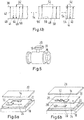
Figures 4a and4b show diagrams of the signal exchange between thecommunication unit 12 and theprocessing unit 14. The diagrams comprise acommunication unit level 38, which represents thecommunication unit 12, and aprocessing unit level 40, which represents theprocessing unit 14. Arrows represent the signals. The tip of an arrow indicates the direction of the signal, i.e. which level receives the signal. The tail of the arrow indicates the source of the signal, i.e. which level sends the signal. - According to
figure 4a , theprocessing unit 14 being represented by theprocessing unit level 40 sends a send message signal 42 to thecommunication unit 12 being represented by thecommunication level 38. Thecommunication unit 12 acknowledges the receipt of the send message signal 42 by providing an Ok-signal 44. Theprocessing unit 14 may receive the Ok-signal 44. Thecommunication unit 12 now tries to send the message to theaccess point device 34. - The message may, for example, be a sensor data signal or a control signal.
- In case that the
communication unit 12 lost the registration or connection at theaccess point device 34, thecommunication unit 12 will not have a working connection to theaccess point device 34. Thus, theaccess point device 34 will not accept the message. Hence, thecommunication unit 12 finds that the message could not be sent. This causes thecommunication unit 12 to send a lostregistration signal 46 to theprocessing unit 14. The lostregistration signal 46 may provide information about a CEREG-EPS registration status. - The
communication device 12 now starts anattachment attempt loop 52 to request a registration at theaccess point device 34, repeatedly. - When the
processing unit 14 receives the lostregistration signal 46, theprocessing unit 14 sends arelease signal 48 to thecommunication unit 12. Thecommunication unit 12 may then detach from theaccess point device 34. Hence, theprocessing unit 14 forces thecommunication unit 12 to detach from theaccess point device 34. - Furthermore, the
processing unit 14 provides a lowpower mode signal 50, which orders thecommunication unit 12 to enter the low power mode. This also terminates theattachment attempt loop 52. - The
processing unit 14 waits the detachment of thecommunication unit 14 and further waits thepredetermined waiting period 54. Thepredetermined waiting period 54 is based on the period, which is required for detaching thecommunication unit 14 and on the power consumption of thedevice 10. Theprocessing unit 14 may monitor the power consumption of thedevice 10. - If the power consumption of the
device 10 is high, theprocessing unit 14 may increase thepredetermined waiting period 54. If the power consumption of thedevice 10 is low, theprocessing unit 14 may decrease thepredetermined waiting period 54. - In addition, the
processing unit 14 may adapt the predetermined waitingperiod 54 based on the detachment period of thecommunication unit 12. A short detachment period may cause theprocessing unit 14 to increase thepredetermined waiting period 54. A long detachment period may cause theprocessing unit 14 to decrease thepredetermined waiting period 54. - After the
predetermined waiting period 54, theprocessing unit 14 provides an attachsignal 56. Upon reception of the attachsignal 56, thecommunication unit 12 enters the active mode and starts to request a registration at theaccess point device 34, i.e. thecommunication unit 12 tries to connect and register to thecommunication network 36. Thecommunication unit 12 carries out the connection and registration attempts during theattachment attempt loop 52. - In case of
figure 4a , the connection attempt of thecommunication unit 12 after receiving the attachsignal 56 is successful, i.e. theaccess point device 34 has registered thecommunication unit 12 for communication. Therefore, thecommunication unit 12 sends an Ok-signal 44 to theprocessing unit 14 and terminates theattachment attempt loop 52. Theprocessing unit 14 provides the send message signal 42 again, such that thecommunication unit 12 may send the message via theaccess point device 34 to thecommunication network 36. Furthermore, thecommunication unit 12 may receive messages from thecommunication network 36 via theaccess point device 34, i.e. from further applications and/or further devices, which comprise a connection to thecommunication network 36. Thecommunication unit 12 may send and receive messages until theaccess point device 34 cancels the registration of thecommunication unit 12, e.g. after thecommunication unit 12 did not communicate with theaccess point device 34 for a long period. - In the case of
figure 4b , the connection attempt of thecommunication unit 12 after receiving the attachsignal 56 is unsuccessful. For example, this might be caused by a high amount of communication from further registered devices with theaccess point device 34, by a shutdown of theaccess point device 34, or by interferences of a wireless connection between thecommunication unit 12 and theaccess point device 34. - After sending the attach
signal 56 which starts theattachment attempt loop 52 at thecommunication unit 12, theprocessing unit 14 waits atimeout period 58. After thetimeout period 58, theprocessing unit 14 checks whether the connection attempt of thecommunication unit 12 is successful. When the check result indicates that thecommunication unit 12 has not been able to get a registration at theaccess point device 34, theprocessing unit 14 sends arelease signal 48 to terminate theattachment attempt loop 52 and to stop any communication between thecommunication unit 12 and theaccess point device 34. Furthermore, theprocessing unit 14 provides a lowpower mode signal 50. Upon reception of the lowpower mode signal 50, thecommunication unit 12 enters the low power mode. Theprocessing unit 14 waits thepredetermined waiting period 54 before sending an attachsignal 56 again. - The
processing unit 14 may increase thepredetermined waiting period 54 based on the number of consecutive check results indicating unsuccessful connection attempts. For example, a high number of unsuccessful connection attempts may cause theprocessing unit 14 to increase thepredetermined waiting period 54. -
Figure 5 shows an example of an embodiment of theutility device 16 comprising thedevice 10. Theutility device 16 may be an ultrasonic flow meter for measuring a flow of a fluid in a tube. However, theutility device 16 may also be another kind of device like a stepper motor, a switch etc. - The ultrasonic flow meter may collect sensor data about the flow. By using the
device 10, theutility device 16 may regularly provide the sensor data to a communication network. This avoids a manual data exchange. Furthermore, theutility device 16 may receive control signals from the communication network by using thedevice 10. - The
utility device 16 may comprise a housing having anupper housing element 20 and alower housing element 18. The housing may comprise a printed circuit board (PCB) with thedevice 10. -
Figures 6a and 6b show alternative embodiments of how theutility device 16 comprises thedevice 10. - According to
figure 6a , the housing comprises a PCB being amain board 22. Themain board 22 comprises theprocessing unit 14, which may be a micro processing unit for controlling theutility device 16. Furthermore, themain board 22 comprises thecommunication unit 12 and anantenna 24 for wireless communication. Thecommunication unit 12 comprises an electrical connection to the antenna and to the micro processing unit. Thecommunication unit 12 and theprocessing unit 14 form thedevice 10. Thelower housing element 18 may be connected to theupper housing element 20 to form a casing for themain board 22. Theupper housing element 20 may comprise a display for displaying the sensor data and/or e.g. status information about theutility device 16. Themain board 22 may comprise further components, e.g. for controlling theutility device 16, for retrieving the sensor data and for providing communication channels between the components of theutility device 16. -
Figure 6b shows an alternative exemplary embodiment of how theutility device 16 comprises thedevice 10. In this exemplary embodiment, theutility device 16 comprises amain board 22 and amodule board 32. - The
main board 22 comprises amain processing unit 30 and a mainboard communication interface 28. Themain processing unit 30 may be a micro processing unit for controlling theutility device 16. Themain processing unit 30 comprises an electrical connection to the mainboard communication interface 28. Furthermore, themain processing unit 30 is configured to transmit and receive signals via the mainboard communication interface 28. - The
module board 32 comprises thecommunication unit 12, theprocessing unit 14, theantenna 24, and a moduleboard communication interface 26. Theprocessing unit 14, which may be a micro processing unit, and thecommunication unit 12 form thedevice 10. Thecommunication unit 12 comprises an electrical connection to theantenna 24 and theprocessing unit 14. Theprocessing unit 14 comprises an electrical connection to the moduleboard communication interface 26. Furthermore, theprocessing unit 14 is configured to transmit and receive signals via the moduleboard communication interface 26. - The housing with the
lower housing element 18 and theupper housing element 20 comprises themodule board 32 and themain board 22. The mainboard communication interface 28 and the moduleboard communication interface 26 are electrically connected to each other. They can forward signals via the electrical connection. This means themain processing unit 30 and theprocessing unit 14 can communicate via the moduleboard communication interface 26 and the mainboard communication interface 28. For example, themain processing unit 30 may provide sensor data from the flow meter to theprocessing unit 14. Theprocessing unit 14 may then order thecommunication unit 12 to send the sensor data as message to thecommunication network 36. - The
module board 32 may be detachable from themain board 22. This allows a replacement of themodule board 32 by another module board, e.g. for providing another communication unit which uses a channel being different from NB-loT. -
Figure 7 shows a flow chart of amethod 100 for establishing a connection between a device according to the above description and an access point device of a communication network. The device comprises a processing unit and a communication unit, wherein the processing unit controls the communication unit. The communication unit may communicate with the access point device of the communication network. - In a
first step 102 of themethod 100, the communication unit provides a lost registration signal if the communication unit cannot establish a connection to the access point device. The lost registration signal indicates that the communication unit is not registered at the access point device, i.e. that the communication unit cannot communicate with the access point device and the communication network. - The communication unit may start a loop in which the communication unit tries to establish a connection with the access point device by requesting a registration at the access point device. The loop may be an attachment attempt loop.
- In a
further step 104, the processing unit receives the lost registration signal. After the reception of the lost registration signal, the processing unit provides a release signal to the communication unit, in astep 106. The release signal forces the communication unit to stop communication or to detach from the access point device. Thus, upon reception of the release signal, the communication unit stops any attempts to communicate with the access point device. - Furthermore, in a
step 108, the processing unit provides a low power mode signal. The communication unit receives the low power mode signal. The low power mode signal orders the communication unit to change from the active mode to the low power mode to save power. - In a
step 110, the processing unit waits a predetermined waiting period. After the predetermined waiting period, the processing unit provides an attach signal to the communication unit. The attach signal transfers the communication unit to the active mode. Furthermore, the attach signal orders the communication unit to establish a connection to the access point device. This starts an attachment attempt loop in which the communication unit repetitively tries to acquire a registration at the access point device. - In a
step 112, after providing the attach signal, the processing unit checks whether the communication unit successfully established a connection to the access point device after a timeout period. - If the check result indicates that the communication unit established a connection to the access point device, the processing unit may provide a send message signal according to
step 114. The send message signal orders the communication unit to send a message being provided by the processing unit. - If the check result indicates, that the communication unit did not establish a connection to the access point device within the timeout period, the processing unit provides a release signal according to
step 116. Furthermore, the processing unit provides a low power mode signal to the communication unit according tostep 118. - Then, the
method 100 continues atstep 110 such that the processing unit waits a predetermined waiting period before providing a further attach signal to the communication unit. - The processing unit may determine how many consecutive times the check result indicates that the communication unit did not establish a connection to the access point device. Based on that number of times, the processing unit may increase the predetermined waiting period. Furthermore, the processing unit may retrieve the power consumption and/or the battery status of the device. The processing unit may then adapt the predetermined waiting period based on the power consumption and/or the battery status of the device.
- A computer program product may implement the
method 100. The computer program product comprises instructions which when executed on a processing unit of a computer instruct the computer to perform the method steps mentioned above. A computer readable medium, e.g. a CD, a flash memory, a floppy disk or any other kind of memory device, may have stored the computer program product. - The invention is not limited to one of the aforementioned embodiments. It can be modified in many ways.
- All features and advantages resulting from the claims, the description and the drawing, including constructive details, spatial arrangements and procedural steps, may be essential for the invention both in themselves and in various combinations.
-
- 10
- device
- 11
- power source
- 12
- communication unit
- 14
- processing unit
- 16
- utility device
- 18
- lower housing element
- 20
- upper housing element
- 22
- main board
- 24
- antenna
- 26
- module board communication interface
- 28
- main board communication interface
- 30
- main processing unit
- 32
- module board
- 34
- access point device
- 36
- communication network
- 38
- communication unit level
- 40
- processing unit level
- 42
- send message signal
- 44
- Ok-signal
- 46
- lost registration signal
- 48
- release signal
- 50
- low power mode signal
- 52
- attachment attempt loop
- 54
- waiting period
- 56
- attach signal
- 58
- timeout period
Claims (15)
- Battery powered device for communicating with an access point device (34) of a communication network (36), the device (10) comprising:- a communication unit (12) for communicating with the access point device (34); and- a processing unit (14) for controlling the communication unit (12);wherein the communication unit (12) comprises at least an active mode and at least a low power mode;
wherein the communication unit (12) is further configured to provide a lost registration signal (46) indicating that the communication unit (12) is not registered at the access point device (34);
wherein the processing unit (14) is configured to receive the lost registration signal (46); wherein, upon reception of the lost registration signal (46), the processing unit (14) is further configured to provide a release signal (48) to the communication unit (12), wherein the release signal (48) forces the communication unit (12) to stop the communication with the access point device (34) or to detach from the access point device (34); wherein, upon reception of the lost registration signal (46), the processing unit (14) is further configured to provide a low power mode signal (50), wherein the low power signal transfers the communication unit (12) into the low power mode,
wherein the processing unit (14) is further configured to provide an attach signal to the communication unit (12) after a predefined waiting period (54), wherein the attach signal transfers the communication unit (12) to the active mode and which orders the communication unit (12) to start communication with the access point device (34). - Battery powered device according to claim 1, wherein, after a predefined timeout period , the processing unit (14) is further configured to check whether the communication unit (12) receives a registration and/or established a connection to the access point device (34) after receiving the attach signal, and, if a check result indicates that the communication unit (12) is not registered or connected to the access point device (34), to provide the release signal (48) and the low power mode signal (50) to the communication unit (12).
- Battery powered device according to claim 2, wherein the processing unit (14) is further configured to increase the predefined waiting period (54) based on a number of how many consecutive check results indicate that the communication unit (12) is not registered at or connected to the access point device (34).
- Battery powered device according to one of claims 1 to 3, wherein the predefined waiting period (54) is based on a power consumption of the device (10).
- Battery powered device according to one of claims 1 to 4, wherein the predefined waiting period (54) is based on a detachment period of the communication unit (12) from the access point device (34).
- Battery powered device according to one of claims 1 to 5, wherein the predefined waiting period (54) increases if the power consumption of the device (10) increases.
- Battery powered device according to one of claims 1 to 6, wherein the communication unit (12) comprises or is combined with a subscriber identity module.
- Battery powered device according one of claims 1 to 7, wherein the processing unit (14) is a micro processing unit.
- Utility device for connecting to the access point device (34) of the communication network (36), the utility device (16) comprising:- a battery powered device (10) according to one of claims 1 to 8; and- an antenna (24) for communicating with an access point of a network (36);wherein the communication unit (12) is connected to the antenna (24); and
wherein the communication unit (12) is configured to provide and receive communication signals via the antenna (24). - Utility device according to claim 9, the utility device further comprising- a main board (22) comprising a main board communication interface (28) and a main processing unit (14); and- a module board (32) comprising a module board communication interface (26) being connected to the main board communication interface (28);wherein the device (10) and the antenna (24) are arranged on the module board (32);
wherein the processing unit (14) is connected to the module board communication interface (26);
wherein the processing unit (14) is configured to provide and receive control signals via the module board communication interface (26);
wherein the main processing unit (30) is connected to the main board communication interface (28), and
wherein the main processing unit (30) is configured to provide and receive control signals via the main board communication interface (28). - Utility device according to claim 9, the utility device further comprising a main board, wherein the device (10) with the communication unit (12) and the main processing unit (14) and the antenna (24) are arranged on the main board.
- Module board for connecting to a main board of a utility device, the module board comprising:- a battery powered device (10) according to one of claims 1 to 8;- a module board communication interface (26) for communicating with the main board (22) of the utility device (16); and- an antenna (24) for communicating with an access point of a network (36);wherein the processing unit (14) is connected to the module board communication interface (26);
wherein the processing unit (14) is configured to provide and receive control signals via the module board communication interface (26);
wherein the communication unit (12) is connected to the antenna (24); and
wherein the communication unit (12) is configured to provide and receive communication signals via the antenna (24). - Method for establishing a connection between a battery powered device according to one of the preceding claims and an access point device of a communication network, the method (100) comprising the following steps:- providing (102) a lost registration signal using the communication unit, the lost registration signal indicating that the communication unit is not registered at the access point device;- receiving (104) the lost registration signal using the processing unit;- providing (106), upon reception of the lost registration signal, a release signal to the communication unit using the processing unit, wherein the release signal forces the communication unit to stop communication with the access point or to detach from the access point device;- providing (108), upon reception of the lost registration signal, a low power mode signal using the processing unit, wherein the low power mode signal transfers the communication unit into the low power mode;- providing (110) an attach signal to the communication unit after a predefined waiting period (54) using the processing unit, wherein the attach signal transfers the communication unit to the active mode and which orders the communication unit to get a registration or to establish a connection to the access point device.
- Computer program product comprising instructions which when executed on a processing unit of a computer instruct the computer to perform the method steps of the method (100) according to claim 12 or 13.
- Computer readable medium having stored the computer program product of claim 14.
Priority Applications (2)
| Application Number | Priority Date | Filing Date | Title |
|---|---|---|---|
| EP19161268.8A EP3706476A1 (en) | 2019-03-07 | 2019-03-07 | Battery powered device for communicating with an access point device of a communication network |
| PCT/EP2020/053078 WO2020177975A1 (en) | 2019-03-07 | 2020-02-07 | Battery powered device for communicating with an access point device of a communication network |
Applications Claiming Priority (1)
| Application Number | Priority Date | Filing Date | Title |
|---|---|---|---|
| EP19161268.8A EP3706476A1 (en) | 2019-03-07 | 2019-03-07 | Battery powered device for communicating with an access point device of a communication network |
Publications (1)
| Publication Number | Publication Date |
|---|---|
| EP3706476A1 true EP3706476A1 (en) | 2020-09-09 |
Family
ID=65724247
Family Applications (1)
| Application Number | Title | Priority Date | Filing Date |
|---|---|---|---|
| EP19161268.8A Withdrawn EP3706476A1 (en) | 2019-03-07 | 2019-03-07 | Battery powered device for communicating with an access point device of a communication network |
Country Status (2)
| Country | Link |
|---|---|
| EP (1) | EP3706476A1 (en) |
| WO (1) | WO2020177975A1 (en) |
Families Citing this family (1)
| Publication number | Priority date | Publication date | Assignee | Title |
|---|---|---|---|---|
| KR20230034059A (en) * | 2021-09-02 | 2023-03-09 | 현대모비스 주식회사 | Uwb on/off operation method to minimize degradation of positioning performance and uwb anchor using the same |
Citations (3)
| Publication number | Priority date | Publication date | Assignee | Title |
|---|---|---|---|---|
| US20110242970A1 (en) * | 2010-04-05 | 2011-10-06 | Qualcomm Incorporated | Methods and apparatus to facilitate relay startup and radio link failure (rlf) handling |
| US20130183971A1 (en) * | 2011-08-11 | 2013-07-18 | Interdigital Patent Holdings, Inc. | Systems And/Or Methods For Providing Relay Mobility |
| US20180070307A1 (en) * | 2016-09-02 | 2018-03-08 | Qualcomm Incorporated | Techniques to reduce power consumption in mobile device during low-power mode |
-
2019
- 2019-03-07 EP EP19161268.8A patent/EP3706476A1/en not_active Withdrawn
-
2020
- 2020-02-07 WO PCT/EP2020/053078 patent/WO2020177975A1/en not_active Ceased
Patent Citations (3)
| Publication number | Priority date | Publication date | Assignee | Title |
|---|---|---|---|---|
| US20110242970A1 (en) * | 2010-04-05 | 2011-10-06 | Qualcomm Incorporated | Methods and apparatus to facilitate relay startup and radio link failure (rlf) handling |
| US20130183971A1 (en) * | 2011-08-11 | 2013-07-18 | Interdigital Patent Holdings, Inc. | Systems And/Or Methods For Providing Relay Mobility |
| US20180070307A1 (en) * | 2016-09-02 | 2018-03-08 | Qualcomm Incorporated | Techniques to reduce power consumption in mobile device during low-power mode |
Also Published As
| Publication number | Publication date |
|---|---|
| WO2020177975A1 (en) | 2020-09-10 |
Similar Documents
| Publication | Publication Date | Title |
|---|---|---|
| CN106879038B (en) | working state switching method and device | |
| KR101629966B1 (en) | Method and appratus for supproting energy saving in a communication system | |
| JP2001103570A (en) | Communication system, communication device and communication method used in this communication system | |
| KR102459543B1 (en) | Communication method and device for a wearable device in a wireless communication system | |
| US8953485B2 (en) | Method and system facilitating communication between user equipment and external network | |
| EP3541086B1 (en) | Systems and methods for network port monitoring using low energy wireless communications | |
| JP2013530598A (en) | Method for operating a mobile station | |
| US11818789B2 (en) | Communication equipment, control method, program, and communication system | |
| US10375756B2 (en) | Method of controlling operation of a communication device, transceiver operating accordingly, and computer program | |
| CN106550438A (en) | Limit method and system, the mobile device of periodic wakeup | |
| WO2020177975A1 (en) | Battery powered device for communicating with an access point device of a communication network | |
| US9510291B2 (en) | M2M devices and communication methods thereof | |
| EP2810494B1 (en) | Gsm signalling for m2m communications | |
| JP2009290718A (en) | Wireless data communication system | |
| CN111145526A (en) | Communication system and method of meter reading equipment | |
| CN111083677A (en) | Low-power-consumption downlink communication system and method | |
| JP4977943B2 (en) | Communications system | |
| KR20240039542A (en) | Method and apparatus for power saving | |
| CN116847440A (en) | Device sleep control method, terminal device and storage medium | |
| JP2004072352A (en) | Portable terminal system, monitor and control method and program to be used for the system and portable terminal | |
| JP4902555B2 (en) | Telemetry device | |
| CN115996373B (en) | Network access method and device of NB-IoT device | |
| JP7755091B1 (en) | MTC device and communication method for the MTC device | |
| CN102665236B (en) | Supervising device | |
| CN103220664B (en) | For the enhancing of power-down sequence |
Legal Events
| Date | Code | Title | Description |
|---|---|---|---|
| PUAI | Public reference made under article 153(3) epc to a published international application that has entered the european phase |
Free format text: ORIGINAL CODE: 0009012 |
|
| STAA | Information on the status of an ep patent application or granted ep patent |
Free format text: STATUS: THE APPLICATION HAS BEEN PUBLISHED |
|
| AK | Designated contracting states |
Kind code of ref document: A1 Designated state(s): AL AT BE BG CH CY CZ DE DK EE ES FI FR GB GR HR HU IE IS IT LI LT LU LV MC MK MT NL NO PL PT RO RS SE SI SK SM TR |
|
| AX | Request for extension of the european patent |
Extension state: BA ME |
|
| STAA | Information on the status of an ep patent application or granted ep patent |
Free format text: STATUS: REQUEST FOR EXAMINATION WAS MADE |
|
| 17P | Request for examination filed |
Effective date: 20201026 |
|
| RBV | Designated contracting states (corrected) |
Designated state(s): AL AT BE BG CH CY CZ DE DK EE ES FI FR GB GR HR HU IE IS IT LI LT LU LV MC MK MT NL NO PL PT RO RS SE SI SK SM TR |
|
| STAA | Information on the status of an ep patent application or granted ep patent |
Free format text: STATUS: EXAMINATION IS IN PROGRESS |
|
| 17Q | First examination report despatched |
Effective date: 20210521 |
|
| STAA | Information on the status of an ep patent application or granted ep patent |
Free format text: STATUS: THE APPLICATION IS DEEMED TO BE WITHDRAWN |
|
| 18D | Application deemed to be withdrawn |
Effective date: 20230131 |