EP3706397A1 - Cover for electronic equipment and electronic equipment - Google Patents
Cover for electronic equipment and electronic equipment Download PDFInfo
- Publication number
- EP3706397A1 EP3706397A1 EP19886037.1A EP19886037A EP3706397A1 EP 3706397 A1 EP3706397 A1 EP 3706397A1 EP 19886037 A EP19886037 A EP 19886037A EP 3706397 A1 EP3706397 A1 EP 3706397A1
- Authority
- EP
- European Patent Office
- Prior art keywords
- cover
- electronic apparatus
- projection
- button
- arc
- Prior art date
- Legal status (The legal status is an assumption and is not a legal conclusion. Google has not performed a legal analysis and makes no representation as to the accuracy of the status listed.)
- Granted
Links
Images








Classifications
-
- H—ELECTRICITY
- H04—ELECTRIC COMMUNICATION TECHNIQUE
- H04M—TELEPHONIC COMMUNICATION
- H04M1/00—Substation equipment, e.g. for use by subscribers
- H04M1/02—Constructional features of telephone sets
- H04M1/23—Construction or mounting of dials or of equivalent devices; Means for facilitating the use thereof
-
- H—ELECTRICITY
- H05—ELECTRIC TECHNIQUES NOT OTHERWISE PROVIDED FOR
- H05K—PRINTED CIRCUITS; CASINGS OR CONSTRUCTIONAL DETAILS OF ELECTRIC APPARATUS; MANUFACTURE OF ASSEMBLAGES OF ELECTRICAL COMPONENTS
- H05K5/00—Casings, cabinets or drawers for electric apparatus
- H05K5/02—Details
- H05K5/03—Covers
-
- H—ELECTRICITY
- H04—ELECTRIC COMMUNICATION TECHNIQUE
- H04M—TELEPHONIC COMMUNICATION
- H04M1/00—Substation equipment, e.g. for use by subscribers
- H04M1/02—Constructional features of telephone sets
-
- H—ELECTRICITY
- H04—ELECTRIC COMMUNICATION TECHNIQUE
- H04M—TELEPHONIC COMMUNICATION
- H04M1/00—Substation equipment, e.g. for use by subscribers
- H04M1/02—Constructional features of telephone sets
- H04M1/0297—Telephone sets adapted to be mounted on a desk or on a wall
Definitions
- the present disclosure relates to a cover for an electronic apparatus and an electronic apparatus.
- an electronic apparatus typified by an ordinary desk telephone is configured so that an operator operates it through buttons.
- buttons circular buttons and/or rectangular buttons are adopted.
- each circular button 101 is disposed in an electronic apparatus in a state where it is passed through a corresponding through hole 102a formed in a first cover 102 and a corresponding through hole 103a formed in a second cover 103.
- each rectangular button 201 is disposed in the electronic apparatus in a state where it is passed through a corresponding through hole 202a formed in a first cover 202 and a corresponding through hole 203a formed in a second cover 203.
- the through hole 102a of the first cover 102 and the through hole 103a of the second cover 103 are formed in a circular shape so as to conform to the shape of the circular button 101. Further, the through hole 202a of the first cover 202 and the through hole 203a of the second cover 203 are formed in a rectangular shape so as to conform to the shape of the rectangular button 201.
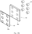
- each of Figs. 17A and 18A shows a state in which the buttons, the first cover, and the second cover are separated from one another
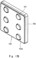
- each of Figs. 17B and 18B shows a state in which the buttons have been passed through the through holes of the first and second covers.
- Patent Literature 1 Japanese Unexamined Utility Model Application Publication No. H2-89882
- a cover for an electronic apparatus includes a through hole into which a button of the electronic apparatus is inserted, in which the through hole is surrounded by:
- An electronic apparatus includes:
- Fig. 1 is a perspective view schematically showing a cover used for an electronic apparatus according to this example embodiment.
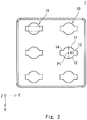
- Fig. 2 is a front view schematically showing the cover used for the electronic apparatus according to this example embodiment.
- a three-dimensional (XYZ) coordinate system is used to clarify the description.
- the X-axis (a first direction) extends in parallel to the surface of the cover
- the Y-axis (a second direction) extends in parallel to the surface of the cover and in a direction orthogonal to the X-axis.
- the Z-axis extends in a direction orthogonal to the X- and Y-axes.
- a Z-axis positive side is the front side of the cover and a Z-axis negative side is the rear side of the cover.
- a cover 1 shown in Figs. 1 and 2 is used for an electronic apparatus such as a desk telephone and is, for example, made of resin. Examples to which the cover 1 is applied will be described later.
- the cover 1 includes through holes 10 that penetrate the cover 1 in the Z-axis direction. As will be described later, buttons of the electronic apparatus are inserted into the through holes 10.
- each through hole 10 is surrounded by a first arc part 11, a second arc part 12, a first projection part 13, and a second projection part 14 as viewed in the Z-axis direction. Further, each through hole 10 has a point-symmetric shape centered at a predefined point PI in the cover 1.
- the first arc part 11 is centered at the predefined point PI and has a first diameter R1.
- the second arc part 12 is disposed so as to be opposed to the first arc part 11 in the X-axis direction. Further, the second arc part 12 is centered at the predefined point PI and has the first diameter R1.
- the first projection part 13 forms a roughly rectangular area that projects from the ends on the Y-axis positive side of the first and second arc parts 11 and 12, and projects toward the Y-axis positive side with respect to the predefined point PI. That is, the part on the X-axis positive side of the first projection part 13 is roughly parallel to the part on the X-axis negative side thereof, and the part on the Y-axis positive side of the first projection part 13 is roughly orthogonal to the parts on the X-axis positive and negative sides thereof. Further, a straight line connecting the ends on the Y-axis negative side of the parts on the X-axis positive and negative sides of the first projection part 13 is roughly parallel to the part on the Y-axis positive side thereof.
- the second projection 14 has a shape that is mirror-symmetric to the shape of the first projection part 13 with a straight line that passes through the predefined point PI and is parallel to the X-axis being the symmetry axis.
- the second projection part 14 forms a roughly rectangular area that projects from the ends on the Y-axis negative side of the first and second arc parts 11 and 12, and projects toward the Y-axis negative side with respect to the predefined point PI.
- the part on the X-axis positive side of the second projection part 14 is roughly parallel to the part on the X-axis negative side thereof, and the part on the Y-axis negative side of the second projection part 14 is roughly orthogonal to the parts on the X-axis positive and negative sides thereof. Further, a straight line connecting the ends on the Y-axis positive side of the parts on the X-axis positive and negative sides of the second projection part 14 is roughly parallel to the part on the Y-axis negative side thereof.
- each through hole 10 of the cover 1 which has the above-described shape, can form a circular shape by connecting the first and second arc parts 11 and 12 (indicated by a single-dashed line), and can form a rectangular shape by connecting the first and second projection parts 13 and 14 (indicated by a double-dashed line). Therefore, the buttons of the electronic apparatus can be inserted into the through holes irrespective of whether they are circular buttons or rectangular buttons. Therefore, there is no need to prepare a cover according to the shapes of buttons. Therefore, the versatility of the cover 1 is improved and the manufacturing cost of the electronic apparatus can be reduced.
- the first diameter R1 is preferably roughly equal to the diameter of a corresponding circular button that is planned to be adopted in the electronic apparatus in advance.
- the rectangular shape that is formed by connecting the first and second projection parts 13 and 14 is preferably roughly identical to the shape formed by the peripheral edges of a corresponding rectangular button that is planned to be adopted in the electronic apparatus in advance. In this way, it is possible to improve the design of the external appearance of the electronic apparatus. Further, it is possible to prevent or minimize the formation of gaps between the through holes 10 of the cover 1 and the buttons of the electronic apparatus.
- buttons whose basic forms are circular buttons will be described.
- Fig. 3 is a perspective view schematically showing one of first buttons according to this example embodiment.
- Fig. 4 is a front view schematically showing the first button according to this example embodiment.
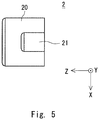
- Fig. 5 is a side view schematically showing the first button according to this example embodiment.
- Fig. 6 is a perspective view schematically showing a state in which the first buttons are inserted into through holes formed in the cover according to this example embodiment.
- Fig. 7 is a front view schematically showing a state in which the first buttons have been inserted into the through holes of the cover according to this example embodiment.
- the first button 2 shown in Figs. 3 to 5 adopts a circular button as its basic form and is, for example, made of resin. Specifically, as shown in Figs. 3 to 5 , the first button 2 is formed so as to be point-symmetric around a central axis O1 of the first button 2. Further, the first button 2 includes a body part 20, a first projection part 21, and a second projection part 22.
- the body part 20 has a roughly circular shape as viewed in the Z-axis direction and extends in the Z-axis direction. That is, the body part 20 has a roughly columnar shape extending in the Z-axis direction. Further, the body part 20 has a diameter roughly equal to the first diameter R1 so that it can be inserted into the through hole 10 of the cover 1.
- the first projection part 21 projects from the part on the Z-axis negative side of the body part 20 toward the Y-axis positive side.
- the first projection part 21 has peripheral edges roughly identical to those of the first projection part 13 of the through hole 10 of the cover 1 so that the first projection part 21 can be inserted into the first projection part 13.
- the first projection part 21 has a roughly rectangular shape as viewed in the Z-axis direction and extends in the Z-axis direction so that its shape conforms to the shape of the first projection part 13 of the through hole 10 of the cover 1.
- the first projection part 21 has a roughly rectangular column shape extending in the Z-axis direction.
- the side on the X-axis positive side of the first projection part 21 is roughly parallel to the side on the X-axis negative side thereof, and the side on the Y-axis positive side of the first projection part 21 is roughly orthogonal to the sides on the X-axis positive and negative sides thereof. Further, a straight line connecting the ends on the Y-axis negative side of the sides on the X-axis positive and negative sides of the first projection part 21 is roughly parallel to the side on the Y-axis positive side thereof.
- the second projection part 22 projects from the part on the Z-axis negative side of the body part 20 toward the Y-axis negative side so that the second projection part 22 is opposed to the first projection part 21.
- the second projection part 22 has peripheral edges roughly identical to those of the second projection part 14 of the through hole 10 of the cover 1 so that the second projection part 22 can be inserted into the second projection part 14.
- the second projection part 22 has a roughly rectangular shape as viewed in the Z-axis direction and extends in the Z-axis direction so that its shape conforms to the shape of the second projection part 14 of the through hole 10 of the cover 1.
- the second projection part 22 has a roughly rectangular column shape extending in the Z-axis direction.
- the side on the X-axis positive side of the second projection part 22 is roughly parallel to the side on the X-axis negative side thereof, and the side on the Y-axis negative side of the second projection part 22 is roughly orthogonal to the sides on the X-axis positive and negative sides thereof. Further, a straight line connecting the ends on the Y-axis positive side of the sides on the X-axis positive and negative sides of the second projection part 22 is roughly parallel to the side on the Y-axis negative side thereof.
- the first button 2 Since the first button 2 has a shape conforming to that of the through hole 10 of the cover 1 as described above, it can be inserted into the through hole 10 of the cover 1 as shown in Figs. 6 and 7 . That is, the first button 2, whose basic form is a circular button, can be inserted into the through hole 10 of the cover 1.
- first and second projection parts 21 and 22 of the first button 2 are inserted into the first and second projection parts 13 and 14, respectively, of the through hole 10 of the cover 1. Therefore, it is possible to prevent a foreign substance from entering from any parts of the through hole 10 of the cover 1 other than the part thereof into which the body part 20 of the first button 2 is inserted.
- Fig. 8 is a perspective view schematically showing one of second buttons according to this example embodiment.
- Fig. 9 is a front view schematically showing the second button according to this example embodiment.
- Fig. 10 is a side view schematically showing the second button according to this example embodiment.
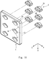
- Fig. 11 is a perspective view schematically showing a state in which the second buttons are inserted into through holes formed in the cover according to this example embodiment.
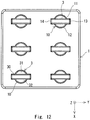
- Fig. 12 is a front view schematically showing a state in which the second buttons have been inserted into the through holes of the cover according to this example embodiment.
- the second button 3 shown in Figs. 8 to 10 adopts a rectangular button as its basic form and is, for example, made of resin. Specifically, as shown in Figs. 8 to 10 , the second button 3 is formed so as to be point-symmetric around a central axis O2 of the second button 3. Further, the second button 3 includes a body part 30, a first projection part 31, and a second projection part 32.
- the body part 30 has a roughly rectangular shape as viewed in the Z-axis direction and extends in the Z-axis direction.
- the body part 30 has a roughly rectangular column shape extending in the Z-axis direction.
- the peripheral edges on both sides in the Y-axis direction of the body part 30 are formed roughly identical to those of the first and second projection parts 13 and 14 so that they can be inserted into the first and second projection parts 13 and 14 of the through hole 10 of the cover 1. That is, the shape of the body part 30 conforms to a rectangular shape that is formed by connecting the first and second projection parts 13 and 14 of the through hole 10 of the cover 1 as viewed in the Z-axis direction.
- the first projection part 31 projects from the part on the Z-axis negative side of the body part 30 toward the X-axis negative side. Further, the first projection part 31 has a peripheral edge roughly identical to that of the first arc part 11 of the through hole 10 of the cover 1 as viewed in the Z-axis direction so that it can be inserted into the first arc part 11 of the through hole 10 of the cover 1.
- the first projection part 31 has an arcuate column shape in which an arcuate projection surrounded by an arc part 31a that is centered at the central axis O2 of the second button 3 and has a diameter roughly equal to the first diameter R1 and the side on the X-axis negative side of the body part 30 extends in the Z-axis direction.
- the second projection part 32 projects from the part on the Z-axis negative side of the body part 30 toward the X-axis positive side so that it is opposed to the first projection part 31. Further, the second projection part 32 has a peripheral edge roughly identical to that of the second arc part 12 of the through hole 10 of the cover 1 as viewed in the Z-axis direction so that it can be inserted into the second arc part 12 of the through hole 10 of the cover 1.
- the second projection part 32 has an arcuate column shape in which an arcuate projection surrounded by an arc part 32a that is centered at the central axis O2 of the second button 3 and has a diameter roughly equal to the first diameter R1 and the side on the X-axis positive side of the body part 30 extends in the Z-axis direction.
- the second button 3 Since the second button 3 has a shape conforming to that of the through hole 10 of the cover 1 as described above, it can be inserted into the through hole 10 of the cover 1 as shown in Figs. 11 and 12 . That is, the second button 3, whose basis form is a rectangular shape, can also be inserted into the through hole 10 of the cover 1.
- first and second projection parts 31 and 32 of the second button 3 are inserted into the first and second arc parts 11 and 12, respectively, of the through hole 10 of the cover 1. Therefore, it is possible to prevent a foreign substance from entering from any parts of the through hole 10 of the cover 1 other than the part thereof into which the body part 30 of the second button 3 is inserted.
- Fig. 13 is an exploded view schematically showing a desk telephone in which a cover and first buttons according to this example embodiment are used.
- Fig. 14 is an assembly diagram schematically showing the desk telephone in which the cover and the first buttons according to the example embodiment are used.
- Fig. 15 is an exploded view schematically showing a desk telephone in which a cover and second buttons according to this example embodiment are used.
- Fig. 16 is an assembly diagram schematically showing the desk telephone in which the cover and the second buttons according to this example embodiment are used.
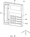
- a cover 1 according to this example embodiment can be applied to at least a part of a cover of a desk telephone 40, which is an example of the electronic apparatus.
- the desk telephone 40 includes a housing 41 in which a circuit board or the like for implementing functions as the desk telephone 40 is disposed, a first cover 42 a part of which the cover 1 according to this example embodiment is applied to, buttons 43, and a handset unit 44. Note that since the details of the desk telephone 40 are not essential to the present disclosure, descriptions thereof will be omitted.
- the cover 1 according to this example embodiment is applied to a part of the first cover 42, there is no need to change the design of the first cover 42 irrespective of whether circular buttons or rectangular buttons are adopted as the buttons 43 of the desk telephone 40. Therefore, it is possible to reduce the manufacturing cost of the desk telephone 40, which is the electronic apparatus.
- buttons 43 it is possible to suitably use, as the buttons 43, the above-described first buttons 2, whose basic forms are circular buttons, and/or the second buttons 3, whose basic forms are rectangular buttons. As a result, it is possible to prevent foreign substances from entering from any parts of the through holes 10 of the first cover 42 other than the parts thereof into which the body parts of the buttons are inserted.
- the desk telephone 40 preferably includes a second cover 45 that covers the first and second projection parts 13 and 14 of the through holes 10 formed in the first cover 42.
- the second cover 45 circular or rectangular through holes 45a having shapes conforming to the shapes of the parts on the Z-axis positive side of the buttons 43 are formed so that the parts on the Z-axis positive side of the buttons 43 are inserted thereinto.
- the second cover 45 covers the first and second projection parts 13 and 14 of the through holes 10 formed in the first cover 42 in a state where the ends on the Z-axis positive side of the buttons 43 are inserted into these through holes 45a.
- cover 1 of the above-described example embodiment is applied to the first cover 42 of the desk telephone 40, it can be applied to any electronic apparatus that is operated by using either circular buttons or rectangular buttons.
Landscapes
- Engineering & Computer Science (AREA)
- Signal Processing (AREA)
- Microelectronics & Electronic Packaging (AREA)
- Telephone Set Structure (AREA)
- Casings For Electric Apparatus (AREA)
- Push-Button Switches (AREA)
Abstract
Description
- The present disclosure relates to a cover for an electronic apparatus and an electronic apparatus.
- As disclosed in
Patent Literature 1, an electronic apparatus typified by an ordinary desk telephone is configured so that an operator operates it through buttons. As the buttons, circular buttons and/or rectangular buttons are adopted. - Further, as shown in
Figs. 17A and17B , eachcircular button 101 is disposed in an electronic apparatus in a state where it is passed through a corresponding throughhole 102a formed in afirst cover 102 and a corresponding throughhole 103a formed in asecond cover 103. Further, in a similar manner, as shown inFigs. 18A and18B , eachrectangular button 201 is disposed in the electronic apparatus in a state where it is passed through a corresponding throughhole 202a formed in afirst cover 202 and a corresponding throughhole 203a formed in asecond cover 203. - Note that the
through hole 102a of thefirst cover 102 and the throughhole 103a of thesecond cover 103 are formed in a circular shape so as to conform to the shape of thecircular button 101. Further, thethrough hole 202a of thefirst cover 202 and the throughhole 203a of thesecond cover 203 are formed in a rectangular shape so as to conform to the shape of therectangular button 201. - Note that each of
Figs. 17A and18A shows a state in which the buttons, the first cover, and the second cover are separated from one another, and each ofFigs. 17B and18B shows a state in which the buttons have been passed through the through holes of the first and second covers. - Patent Literature 1: Japanese Unexamined Utility Model Application Publication No.
H2-89882 - As shown in
Figs. 17A ,17B ,18A and18B , through holes formed in an ordinary first cover are formed in shapes that conform to the shapes of buttons. Therefore, there is a problem that it is necessary to prepare the first cover according to the shapes of buttons and hence the manufacturing cost of the electronic apparatus increases. - One of the objects that an example embodiment disclosed in this specification is intended to achieve is to provide a cover for an electronic apparatus and an electronic apparatus capable of contributing to a solution of the above-described problem. It should be noted that this object is merely one of a plurality of objects that example embodiments disclosed in this specification are intended to achieve. Other objects or problems and novel features will be made apparent from the following description and the accompanying drawings.
- A cover for an electronic apparatus according to a first aspect includes a through hole into which a button of the electronic apparatus is inserted, in which
the through hole is surrounded by: - a first arc part centered at a predefined point;
- a second arc part positioned to be opposed to the first arc part in a first direction parallel to a surface of the cover, the second arc part being centered at the predefined point and having a diameter equal to that of the first arc part;
- a first projection part forming a rectangular area projecting from one end of the first arc part and one end of the second arc part, the rectangular area projecting outward with respect to the predefined point in a second direction, the second direction being parallel to the surface of the cover and orthogonal to the first direction; and
- a second projection part forming a rectangular area projecting from the other end of the first arc part and the other end of the second arc part, the rectangular area projecting outward with respect to the predefined point in the second direction.
- An electronic apparatus according to a second aspect includes:
- the above-described cover for the electronic apparatus; and
- a button configured to be inserted into the through hole of the cover for the electronic apparatus.
- According to the above-described aspect, it is possible to provide a cover for an electronic apparatus and an electronic apparatus by which the manufacturing cost of the electronic apparatus can be reduced.
-
-
Fig. 1 is a perspective view schematically showing a cover used for an electronic apparatus according to an example embodiment; -
Fig. 2 is a front view schematically showing the cover used for the electronic apparatus according to the example embodiment; -
Fig. 3 is a perspective view schematically showing one of first buttons according to an example embodiment; -
Fig. 4 is a front view schematically showing the first button according to the example embodiment; -
Fig. 5 is a side view schematically showing the first button according to the example embodiment; -
Fig. 6 is a perspective view schematically showing a state in which first buttons are inserted into through holes formed in a cover according to an example embodiment; -
Fig. 7 is a front view schematically showing a state in which the first buttons have been inserted into the through holes of the cover according to the example embodiment; -
Fig. 8 is a perspective view schematically showing one of second buttons according to an example embodiment; -
Fig. 9 is a front view schematically showing the second button according to the example embodiment; -
Fig. 10 is a side view schematically showing the second button according to the example embodiment; -
Fig. 11 is a perspective view schematically showing a state in which second buttons are inserted into through holes formed in a cover according to an example embodiment; -
Fig. 12 is a front view schematically showing a state in which the second buttons have been inserted into the through holes of the cover according to the example embodiment; -
Fig. 13 is an exploded view schematically showing a desk telephone in which a cover and first buttons according to an example embodiment are used; -
Fig. 14 is an assembly diagram schematically showing the desk telephone in which the cover and the first buttons according to the example embodiment are used; -
Fig. 15 is an exploded view schematically showing a desk telephone in which a cover and second buttons according to an example embodiment are used; -
Fig. 16 is an assembly diagram schematically showing the desk telephone in which the cover and the second buttons according to the example embodiment are used; -
Fig. 17A shows a state in which ordinary circular buttons, a first cover, and a second cover are separated from one another; -
Fig. 17B shows a state in which the ordinary circular buttons have been passed through through holes formed in the first and second covers; -
Fig. 18A shows a state in which ordinary rectangular buttons, a first cover, and a second cover are separated from one another; and -
Fig. 18B shows a state in which the ordinary rectangular buttons have been passed through through holes formed in the first and second covers. - A best mode for carrying out the present invention will be described hereinafter with reference to the accompanying drawings. However, the present invention is not limited to the below-shown example embodiments. Further, to clarify the explanation, the following description and drawings are simplified as appropriate.
- Firstly, a configuration of a cover used for an electronic apparatus according to this example embodiment will be described.
Fig. 1 is a perspective view schematically showing a cover used for an electronic apparatus according to this example embodiment.Fig. 2 is a front view schematically showing the cover used for the electronic apparatus according to this example embodiment. - Note that in the following explanation, a three-dimensional (XYZ) coordinate system is used to clarify the description. Note that the X-axis (a first direction) extends in parallel to the surface of the cover, and the Y-axis (a second direction) extends in parallel to the surface of the cover and in a direction orthogonal to the X-axis. Further, the Z-axis extends in a direction orthogonal to the X- and Y-axes. Further, a Z-axis positive side is the front side of the cover and a Z-axis negative side is the rear side of the cover.
- A
cover 1 shown inFigs. 1 and2 is used for an electronic apparatus such as a desk telephone and is, for example, made of resin. Examples to which thecover 1 is applied will be described later. As shown inFigs. 1 and2 , thecover 1 includes throughholes 10 that penetrate thecover 1 in the Z-axis direction. As will be described later, buttons of the electronic apparatus are inserted into the through holes 10. - Specifically, each through
hole 10 is surrounded by afirst arc part 11, asecond arc part 12, afirst projection part 13, and asecond projection part 14 as viewed in the Z-axis direction. Further, each throughhole 10 has a point-symmetric shape centered at a predefined point PI in thecover 1. - The
first arc part 11 is centered at the predefined point PI and has a first diameter R1. Thesecond arc part 12 is disposed so as to be opposed to thefirst arc part 11 in the X-axis direction. Further, thesecond arc part 12 is centered at the predefined point PI and has the first diameter R1. - The
first projection part 13 forms a roughly rectangular area that projects from the ends on the Y-axis positive side of the first andsecond arc parts first projection part 13 is roughly parallel to the part on the X-axis negative side thereof, and the part on the Y-axis positive side of thefirst projection part 13 is roughly orthogonal to the parts on the X-axis positive and negative sides thereof. Further, a straight line connecting the ends on the Y-axis negative side of the parts on the X-axis positive and negative sides of thefirst projection part 13 is roughly parallel to the part on the Y-axis positive side thereof. - The
second projection 14 has a shape that is mirror-symmetric to the shape of thefirst projection part 13 with a straight line that passes through the predefined point PI and is parallel to the X-axis being the symmetry axis. Thesecond projection part 14 forms a roughly rectangular area that projects from the ends on the Y-axis negative side of the first andsecond arc parts - That is, the part on the X-axis positive side of the
second projection part 14 is roughly parallel to the part on the X-axis negative side thereof, and the part on the Y-axis negative side of thesecond projection part 14 is roughly orthogonal to the parts on the X-axis positive and negative sides thereof. Further, a straight line connecting the ends on the Y-axis positive side of the parts on the X-axis positive and negative sides of thesecond projection part 14 is roughly parallel to the part on the Y-axis negative side thereof. - As shown in
Fig. 2 , each throughhole 10 of thecover 1, which has the above-described shape, can form a circular shape by connecting the first andsecond arc parts 11 and 12 (indicated by a single-dashed line), and can form a rectangular shape by connecting the first andsecond projection parts 13 and 14 (indicated by a double-dashed line). Therefore, the buttons of the electronic apparatus can be inserted into the through holes irrespective of whether they are circular buttons or rectangular buttons. Therefore, there is no need to prepare a cover according to the shapes of buttons. Therefore, the versatility of thecover 1 is improved and the manufacturing cost of the electronic apparatus can be reduced. - Note that the first diameter R1 is preferably roughly equal to the diameter of a corresponding circular button that is planned to be adopted in the electronic apparatus in advance. Further, the rectangular shape that is formed by connecting the first and
second projection parts holes 10 of thecover 1 and the buttons of the electronic apparatus. - Next, a preferred configuration of a button that is inserted into a through
hole 10 formed in thecover 1 according to this example embodiment will be described. Firstly, first buttons whose basic forms are circular buttons will be described.Fig. 3 is a perspective view schematically showing one of first buttons according to this example embodiment.Fig. 4 is a front view schematically showing the first button according to this example embodiment.Fig. 5 is a side view schematically showing the first button according to this example embodiment.Fig. 6 is a perspective view schematically showing a state in which the first buttons are inserted into through holes formed in the cover according to this example embodiment.Fig. 7 is a front view schematically showing a state in which the first buttons have been inserted into the through holes of the cover according to this example embodiment. - As described above, the
first button 2 shown inFigs. 3 to 5 adopts a circular button as its basic form and is, for example, made of resin. Specifically, as shown inFigs. 3 to 5 , thefirst button 2 is formed so as to be point-symmetric around a central axis O1 of thefirst button 2. Further, thefirst button 2 includes abody part 20, afirst projection part 21, and asecond projection part 22. - The
body part 20 has a roughly circular shape as viewed in the Z-axis direction and extends in the Z-axis direction. That is, thebody part 20 has a roughly columnar shape extending in the Z-axis direction. Further, thebody part 20 has a diameter roughly equal to the first diameter R1 so that it can be inserted into the throughhole 10 of thecover 1. - The
first projection part 21 projects from the part on the Z-axis negative side of thebody part 20 toward the Y-axis positive side. Thefirst projection part 21 has peripheral edges roughly identical to those of thefirst projection part 13 of the throughhole 10 of thecover 1 so that thefirst projection part 21 can be inserted into thefirst projection part 13. - That is, the
first projection part 21 has a roughly rectangular shape as viewed in the Z-axis direction and extends in the Z-axis direction so that its shape conforms to the shape of thefirst projection part 13 of the throughhole 10 of thecover 1. In other words, thefirst projection part 21 has a roughly rectangular column shape extending in the Z-axis direction. - Therefore, the side on the X-axis positive side of the
first projection part 21 is roughly parallel to the side on the X-axis negative side thereof, and the side on the Y-axis positive side of thefirst projection part 21 is roughly orthogonal to the sides on the X-axis positive and negative sides thereof. Further, a straight line connecting the ends on the Y-axis negative side of the sides on the X-axis positive and negative sides of thefirst projection part 21 is roughly parallel to the side on the Y-axis positive side thereof. - The
second projection part 22 projects from the part on the Z-axis negative side of thebody part 20 toward the Y-axis negative side so that thesecond projection part 22 is opposed to thefirst projection part 21. Thesecond projection part 22 has peripheral edges roughly identical to those of thesecond projection part 14 of the throughhole 10 of thecover 1 so that thesecond projection part 22 can be inserted into thesecond projection part 14. - That is, the
second projection part 22 has a roughly rectangular shape as viewed in the Z-axis direction and extends in the Z-axis direction so that its shape conforms to the shape of thesecond projection part 14 of the throughhole 10 of thecover 1. In other words, thesecond projection part 22 has a roughly rectangular column shape extending in the Z-axis direction. - Therefore, the side on the X-axis positive side of the
second projection part 22 is roughly parallel to the side on the X-axis negative side thereof, and the side on the Y-axis negative side of thesecond projection part 22 is roughly orthogonal to the sides on the X-axis positive and negative sides thereof. Further, a straight line connecting the ends on the Y-axis positive side of the sides on the X-axis positive and negative sides of thesecond projection part 22 is roughly parallel to the side on the Y-axis negative side thereof. - Since the
first button 2 has a shape conforming to that of the throughhole 10 of thecover 1 as described above, it can be inserted into the throughhole 10 of thecover 1 as shown inFigs. 6 and7 . That is, thefirst button 2, whose basic form is a circular button, can be inserted into the throughhole 10 of thecover 1. - Further, the first and
second projection parts first button 2 are inserted into the first andsecond projection parts hole 10 of thecover 1. Therefore, it is possible to prevent a foreign substance from entering from any parts of the throughhole 10 of thecover 1 other than the part thereof into which thebody part 20 of thefirst button 2 is inserted. - In addition, in a state where the
first button 2 is inserted into the throughhole 10 of thecover 1, roughly the entire area of the peripheral edges of thefirst button 2 is restrained by the peripheral edges of the throughhole 10 of thecover 1. Therefore, it is possible to prevent thefirst button 2 from rattling. - Next, second buttons whose basic forms are rectangular buttons will be described.
Fig. 8 is a perspective view schematically showing one of second buttons according to this example embodiment.Fig. 9 is a front view schematically showing the second button according to this example embodiment.Fig. 10 is a side view schematically showing the second button according to this example embodiment.Fig. 11 is a perspective view schematically showing a state in which the second buttons are inserted into through holes formed in the cover according to this example embodiment.Fig. 12 is a front view schematically showing a state in which the second buttons have been inserted into the through holes of the cover according to this example embodiment. - As described above, the
second button 3 shown inFigs. 8 to 10 adopts a rectangular button as its basic form and is, for example, made of resin. Specifically, as shown inFigs. 8 to 10 , thesecond button 3 is formed so as to be point-symmetric around a central axis O2 of thesecond button 3. Further, thesecond button 3 includes abody part 30, afirst projection part 31, and asecond projection part 32. - The
body part 30 has a roughly rectangular shape as viewed in the Z-axis direction and extends in the Z-axis direction. In other words, thebody part 30 has a roughly rectangular column shape extending in the Z-axis direction. Further, the peripheral edges on both sides in the Y-axis direction of thebody part 30 are formed roughly identical to those of the first andsecond projection parts second projection parts hole 10 of thecover 1. That is, the shape of thebody part 30 conforms to a rectangular shape that is formed by connecting the first andsecond projection parts hole 10 of thecover 1 as viewed in the Z-axis direction. - The
first projection part 31 projects from the part on the Z-axis negative side of thebody part 30 toward the X-axis negative side. Further, thefirst projection part 31 has a peripheral edge roughly identical to that of thefirst arc part 11 of the throughhole 10 of thecover 1 as viewed in the Z-axis direction so that it can be inserted into thefirst arc part 11 of the throughhole 10 of thecover 1. - That is, as shown in
Fig. 9 , thefirst projection part 31 has an arcuate column shape in which an arcuate projection surrounded by anarc part 31a that is centered at the central axis O2 of thesecond button 3 and has a diameter roughly equal to the first diameter R1 and the side on the X-axis negative side of thebody part 30 extends in the Z-axis direction. - The
second projection part 32 projects from the part on the Z-axis negative side of thebody part 30 toward the X-axis positive side so that it is opposed to thefirst projection part 31. Further, thesecond projection part 32 has a peripheral edge roughly identical to that of thesecond arc part 12 of the throughhole 10 of thecover 1 as viewed in the Z-axis direction so that it can be inserted into thesecond arc part 12 of the throughhole 10 of thecover 1. - That is, as shown in
Fig. 9 , thesecond projection part 32 has an arcuate column shape in which an arcuate projection surrounded by anarc part 32a that is centered at the central axis O2 of thesecond button 3 and has a diameter roughly equal to the first diameter R1 and the side on the X-axis positive side of thebody part 30 extends in the Z-axis direction. - Since the
second button 3 has a shape conforming to that of the throughhole 10 of thecover 1 as described above, it can be inserted into the throughhole 10 of thecover 1 as shown inFigs. 11 and12 . That is, thesecond button 3, whose basis form is a rectangular shape, can also be inserted into the throughhole 10 of thecover 1. - Further, the first and
second projection parts second button 3 are inserted into the first andsecond arc parts hole 10 of thecover 1. Therefore, it is possible to prevent a foreign substance from entering from any parts of the throughhole 10 of thecover 1 other than the part thereof into which thebody part 30 of thesecond button 3 is inserted. - In addition, in a state where the
second button 3 is inserted into the throughhole 10 of thecover 1, roughly the entire area of the peripheral edges of thesecond button 3 is restrained by the peripheral edges of the throughhole 10 of thecover 1. Therefore, it is possible to prevent thesecond button 3 from rattling. - Next, an example to which the
cover 1 according to this example embodiment is applied will be described.Fig. 13 is an exploded view schematically showing a desk telephone in which a cover and first buttons according to this example embodiment are used.Fig. 14 is an assembly diagram schematically showing the desk telephone in which the cover and the first buttons according to the example embodiment are used.Fig. 15 is an exploded view schematically showing a desk telephone in which a cover and second buttons according to this example embodiment are used.Fig. 16 is an assembly diagram schematically showing the desk telephone in which the cover and the second buttons according to this example embodiment are used. - As shown in
Figs. 13 and15 , acover 1 according to this example embodiment can be applied to at least a part of a cover of adesk telephone 40, which is an example of the electronic apparatus. Specifically, thedesk telephone 40 includes ahousing 41 in which a circuit board or the like for implementing functions as thedesk telephone 40 is disposed, a first cover 42 a part of which thecover 1 according to this example embodiment is applied to,buttons 43, and ahandset unit 44. Note that since the details of thedesk telephone 40 are not essential to the present disclosure, descriptions thereof will be omitted. - In the
desk telephone 40, since thecover 1 according to this example embodiment is applied to a part of thefirst cover 42, there is no need to change the design of thefirst cover 42 irrespective of whether circular buttons or rectangular buttons are adopted as thebuttons 43 of thedesk telephone 40. Therefore, it is possible to reduce the manufacturing cost of thedesk telephone 40, which is the electronic apparatus. - Note that as shown in
Figs. 13 and15 , it is possible to suitably use, as thebuttons 43, the above-describedfirst buttons 2, whose basic forms are circular buttons, and/or thesecond buttons 3, whose basic forms are rectangular buttons. As a result, it is possible to prevent foreign substances from entering from any parts of the throughholes 10 of thefirst cover 42 other than the parts thereof into which the body parts of the buttons are inserted. - Note that as shown in
Figs. 14 and16 , thedesk telephone 40 preferably includes asecond cover 45 that covers the first andsecond projection parts holes 10 formed in thefirst cover 42. In thesecond cover 45, circular or rectangular throughholes 45a having shapes conforming to the shapes of the parts on the Z-axis positive side of thebuttons 43 are formed so that the parts on the Z-axis positive side of thebuttons 43 are inserted thereinto. Further, thesecond cover 45 covers the first andsecond projection parts holes 10 formed in thefirst cover 42 in a state where the ends on the Z-axis positive side of thebuttons 43 are inserted into these throughholes 45a. - As a result, it is possible to prevent foreign substances from entering gaps between the first and
second projection parts holes 10 formed in thefirst cover 42 and the projection parts of the buttons 43 (i.e., the first andsecond projection parts first buttons 2, or the first andsecond projection parts desk telephone 40. - Although the present disclosure is explained above with reference to example embodiments, the present disclosure is not limited to the above-described example embodiments. Various modifications that can be understood by those skilled in the art can be made to the configuration and details of the present disclosure within the scope of the invention.
- Although the
cover 1 of the above-described example embodiment is applied to thefirst cover 42 of thedesk telephone 40, it can be applied to any electronic apparatus that is operated by using either circular buttons or rectangular buttons. - This application is based upon and claims the benefit of priority from Japanese patent application No.
2019-8372, filed on January 22, 2019 -
- 1
- COVER (COVER FOR ELECTRONIC APPARATUS)
- 10
- THROUGH HOLE
- 11
- FIRST ARC PART
- 12
- SECOND ARC PART
- 13
- FIRST PROJECTION PART
- 14
- SECOND PROJECTION PART
- 2
- FIRST BUTTON
- 20
- BODY PART
- 21
- FIRST PROJECTION PART
- 22
- SECOND PROJECTION PART
- 3
- SECOND BUTTON
- 30
- BODY PART
- 31
- FIRST PROJECTION PART
- 32
- SECOND PROJECTION PART
- 40
- DESK TELEPHONE
- 42
- FIRST COVER
- 43
- BUTTON
- 45
- SECOND COVER
- 45a
- THROUGH HOLE
Claims (7)
- A cover for an electronic apparatus, comprising a through hole into which a button of the electronic apparatus is inserted, wherein
the through hole is surrounded by:a first arc part centered at a predefined point;a second arc part positioned to be opposed to the first arc part in a first direction parallel to a surface of the cover, the second arc part being centered at the predefined point and having a diameter equal to that of the first arc part;a first projection part forming a rectangular area projecting from one end of the first arc part and one end of the second arc part, the rectangular area projecting outward with respect to the predefined point in a second direction, the second direction being parallel to the surface of the cover and orthogonal to the first direction; anda second projection part forming a rectangular area projecting from the other end of the first arc part and the other end of the second arc part, the rectangular area projecting outward with respect to the predefined point in the second direction. - The cover for an electronic apparatus according to Claim 1, wherein a diameter of the first and second arc parts is equal to a predefined diameter of a circular button in the electronic apparatus.
- The cover for an electronic apparatus according to Claim 1 or 2, wherein first and second projection parts are identical to predefined peripheral edges of ends in the second direction of a rectangular button of the electronic apparatus.
- An electronic apparatus comprising:a cover for an electronic apparatus according to any one of Claims 1 to 3; anda button configured to be inserted into a through hole formed in the cover for the electronic apparatus.
- The electronic apparatus according to Claim 4, wherein the button comprises:a circular body part having a diameter equal to that of the first and second arc parts of the cover for the electronic apparatus;a first projection part having a peripheral edge identical to that of a first projection part of the cover for the electronic apparatus, the first projection part being a rectangular projection projecting from one of parts of the body part in a third direction orthogonal to a surface of the cover for the electronic apparatus; anda second projection part having a peripheral edge identical to that of a second projection part of the cover for the electronic apparatus, the second projection part being a rectangular projection that projects from one of the parts of the body part in the third direction so that the second projection part is opposed to the first projection part in the second direction.
- The electronic apparatus according to Claim 4, wherein the button comprises:a rectangular body part having peripheral edges on both sides thereof in the second direction, the peripheral edges being identical to those of the first and second projection parts of the cover for the electronic apparatus;a first projection part having a peripheral edge identical to that of a first arc part of the cover for the electronic apparatus, the first projection part being an arcuate projection that projects from one of parts of the body part in a third direction orthogonal to a surface of the cover for the electronic apparatus; anda second projection part having a peripheral edge identical to that of a second arc part of the cover for the electronic apparatus, the second projection part being an arcuate projection that projects from one of the parts of the body part in the third direction so that the second projection part is opposed to the first projection part in the first direction.
- The electronic apparatus according to Claim 5 or 6, further comprising a second cover, wherein
the second cover has a through hole into which the other part of the body part in the third direction is inserted; and
the second cover is configured to cover the cover for the electronic apparatus, and cover the first and second projection parts of the cover for the electronic apparatus.
Applications Claiming Priority (2)
| Application Number | Priority Date | Filing Date | Title |
|---|---|---|---|
| JP2019008372A JP6669371B1 (en) | 2019-01-22 | 2019-01-22 | Electronic equipment cover and electronic equipment |
| PCT/JP2019/048954 WO2020153043A1 (en) | 2019-01-22 | 2019-12-13 | Cover for electronic equipment and electronic equipment |
Publications (4)
| Publication Number | Publication Date |
|---|---|
| EP3706397A1 true EP3706397A1 (en) | 2020-09-09 |
| EP3706397A4 EP3706397A4 (en) | 2021-06-23 |
| EP3706397C0 EP3706397C0 (en) | 2024-08-07 |
| EP3706397B1 EP3706397B1 (en) | 2024-08-07 |
Family
ID=70000702
Family Applications (1)
| Application Number | Title | Priority Date | Filing Date |
|---|---|---|---|
| EP19886037.1A Active EP3706397B1 (en) | 2019-01-22 | 2019-12-13 | Electronic equipment with cover |
Country Status (7)
| Country | Link |
|---|---|
| US (1) | US11395426B2 (en) |
| EP (1) | EP3706397B1 (en) |
| JP (1) | JP6669371B1 (en) |
| CN (1) | CN111727670B (en) |
| AU (1) | AU2019369207B2 (en) |
| CA (1) | CA3084415C (en) |
| WO (1) | WO2020153043A1 (en) |
Family Cites Families (16)
| Publication number | Priority date | Publication date | Assignee | Title |
|---|---|---|---|---|
| JPS6370629U (en) | 1986-10-29 | 1988-05-12 | ||
| JPH0289882U (en) | 1988-12-28 | 1990-07-17 | ||
| FR2740913B1 (en) | 1995-11-07 | 1997-12-05 | Framatome Connectors France | HOLDING AND CONTACT ELEMENT AND CONNECTOR COMPRISING SAME |
| JPH11306903A (en) | 1998-04-23 | 1999-11-05 | Canon Inc | control panel |
| TWM245687U (en) * | 2003-07-11 | 2004-10-01 | Hon Hai Prec Ind Co Ltd | Repalceable panel for handset |
| GB2409596A (en) | 2003-12-23 | 2005-06-29 | Nokia Corp | Handset with squeezable body |
| TWI289280B (en) | 2006-01-24 | 2007-11-01 | Chunghwa Picture Tubes Ltd | Mounting button used in display module |
| CN201263263Y (en) | 2008-09-28 | 2009-06-24 | 姚国祥 | Controller outer shell suitable for mounting various shapes key-press |
| TWM358501U (en) | 2008-11-12 | 2009-06-01 | Altek Corp | Case structure with keypad |
| CN201303361Y (en) | 2008-11-28 | 2009-09-02 | 高艺 | Multifunctional telephone |
| CN102118927A (en) | 2009-12-30 | 2011-07-06 | 深圳富泰宏精密工业有限公司 | Shell assembly structure of portable electronic device |
| JP5587143B2 (en) | 2010-11-15 | 2014-09-10 | 株式会社三谷バルブ | Continuous operation mode setting mechanism and aerosol type product equipped with this continuous operation mode setting mechanism |
| CN205725872U (en) | 2016-03-17 | 2016-11-23 | 中兴通讯股份有限公司 | A kind of button and terminal |
| JP6729849B2 (en) | 2016-07-22 | 2020-07-29 | 株式会社デンソーテン | Operation unit assembly structure |
| CN206136021U (en) | 2016-11-18 | 2017-04-26 | 安徽国越电子科技有限公司 | IP audio frequency telephone terminal |
| JP6979804B2 (en) | 2017-06-20 | 2021-12-15 | キヤノン株式会社 | Information processing equipment, its control method, and programs |
-
2019
- 2019-01-22 JP JP2019008372A patent/JP6669371B1/en active Active
- 2019-12-13 AU AU2019369207A patent/AU2019369207B2/en active Active
- 2019-12-13 EP EP19886037.1A patent/EP3706397B1/en active Active
- 2019-12-13 CN CN201980005915.2A patent/CN111727670B/en active Active
- 2019-12-13 US US16/762,973 patent/US11395426B2/en active Active
- 2019-12-13 WO PCT/JP2019/048954 patent/WO2020153043A1/en not_active Ceased
- 2019-12-13 CA CA3084415A patent/CA3084415C/en active Active
Also Published As
| Publication number | Publication date |
|---|---|
| JP6669371B1 (en) | 2020-03-18 |
| AU2019369207B2 (en) | 2022-12-08 |
| CA3084415A1 (en) | 2020-07-22 |
| EP3706397A4 (en) | 2021-06-23 |
| CN111727670A (en) | 2020-09-29 |
| EP3706397C0 (en) | 2024-08-07 |
| AU2019369207A1 (en) | 2020-08-06 |
| US11395426B2 (en) | 2022-07-19 |
| CA3084415C (en) | 2022-11-29 |
| JP2020119951A (en) | 2020-08-06 |
| US20210219447A1 (en) | 2021-07-15 |
| CN111727670B (en) | 2021-09-03 |
| WO2020153043A1 (en) | 2020-07-30 |
| EP3706397B1 (en) | 2024-08-07 |
Similar Documents
| Publication | Publication Date | Title |
|---|---|---|
| RU2654345C2 (en) | Antenna device for portable terminal | |
| KR20200027734A (en) | Fordable device comprising antenna | |
| KR20200101791A (en) | Pordable device | |
| EP3934052A1 (en) | Electronic device/charger set, and communication system | |
| EP4287594A1 (en) | Terminal device | |
| JP2017069867A (en) | Electronic device, pen, and pen holding method | |
| US20140079240A1 (en) | Bluetooth headset | |
| US8982580B2 (en) | Electronic device | |
| JP2008218526A (en) | Shield case and electronic equipment | |
| US11395426B2 (en) | Cover for electronic apparatus and electronic apparatus | |
| JP2018045817A (en) | Locking mechanism, connector, and wire harness | |
| US10827105B1 (en) | Lens module and electronic device using the lens module | |
| JP2020512792A (en) | Mobile device external assembly and mobile device protective sleeve | |
| KR20200045892A (en) | Usb terminal assembly | |
| CN206948600U (en) | A kind of electroacoustic transducer and electronic equipment | |
| CN105757922A (en) | Air conditioner and microphone assembly thereof | |
| WO2024113307A1 (en) | Earphone case and electronic device | |
| JP2018031997A (en) | Fitting structure of name plate | |
| WO2017047035A1 (en) | Holding structure and electric device | |
| CN218888673U (en) | Wireless earphone and earphone assembly | |
| CN105933812B (en) | An earphone holder and a terminal device | |
| JP2014093453A (en) | Electronic apparatus | |
| JP2020150468A (en) | Portable terminal | |
| JP2019128977A (en) | Electric connector | |
| JP6606152B2 (en) | Electronic equipment and electronic equipment system |
Legal Events
| Date | Code | Title | Description |
|---|---|---|---|
| STAA | Information on the status of an ep patent application or granted ep patent |
Free format text: STATUS: UNKNOWN |
|
| STAA | Information on the status of an ep patent application or granted ep patent |
Free format text: STATUS: THE INTERNATIONAL PUBLICATION HAS BEEN MADE |
|
| PUAI | Public reference made under article 153(3) epc to a published international application that has entered the european phase |
Free format text: ORIGINAL CODE: 0009012 |
|
| STAA | Information on the status of an ep patent application or granted ep patent |
Free format text: STATUS: REQUEST FOR EXAMINATION WAS MADE |
|
| 17P | Request for examination filed |
Effective date: 20200525 |
|
| AK | Designated contracting states |
Kind code of ref document: A1 Designated state(s): AL AT BE BG CH CY CZ DE DK EE ES FI FR GB GR HR HU IE IS IT LI LT LU LV MC MK MT NL NO PL PT RO RS SE SI SK SM TR |
|
| AX | Request for extension of the european patent |
Extension state: BA ME |
|
| STAA | Information on the status of an ep patent application or granted ep patent |
Free format text: STATUS: EXAMINATION IS IN PROGRESS |
|
| A4 | Supplementary search report drawn up and despatched |
Effective date: 20210521 |
|
| RIC1 | Information provided on ipc code assigned before grant |
Ipc: H04M 1/02 20060101AFI20210517BHEP Ipc: H04M 1/23 20060101ALI20210517BHEP |
|
| 17Q | First examination report despatched |
Effective date: 20210616 |
|
| DAV | Request for validation of the european patent (deleted) | ||
| DAX | Request for extension of the european patent (deleted) | ||
| GRAP | Despatch of communication of intention to grant a patent |
Free format text: ORIGINAL CODE: EPIDOSNIGR1 |
|
| STAA | Information on the status of an ep patent application or granted ep patent |
Free format text: STATUS: GRANT OF PATENT IS INTENDED |
|
| INTG | Intention to grant announced |
Effective date: 20240314 |
|
| GRAS | Grant fee paid |
Free format text: ORIGINAL CODE: EPIDOSNIGR3 |
|
| GRAA | (expected) grant |
Free format text: ORIGINAL CODE: 0009210 |
|
| STAA | Information on the status of an ep patent application or granted ep patent |
Free format text: STATUS: THE PATENT HAS BEEN GRANTED |
|
| AK | Designated contracting states |
Kind code of ref document: B1 Designated state(s): AL AT BE BG CH CY CZ DE DK EE ES FI FR GB GR HR HU IE IS IT LI LT LU LV MC MK MT NL NO PL PT RO RS SE SI SK SM TR |
|
| REG | Reference to a national code |
Ref country code: GB Ref legal event code: FG4D |
|
| REG | Reference to a national code |
Ref country code: CH Ref legal event code: EP |
|
| REG | Reference to a national code |
Ref country code: IE Ref legal event code: FG4D |
|
| REG | Reference to a national code |
Ref country code: DE Ref legal event code: R096 Ref document number: 602019056776 Country of ref document: DE |
|
| U01 | Request for unitary effect filed |
Effective date: 20240807 |
|
| U07 | Unitary effect registered |
Designated state(s): AT BE BG DE DK EE FI FR IT LT LU LV MT NL PT SE SI Effective date: 20240822 |
|
| PG25 | Lapsed in a contracting state [announced via postgrant information from national office to epo] |
Ref country code: NO Free format text: LAPSE BECAUSE OF FAILURE TO SUBMIT A TRANSLATION OF THE DESCRIPTION OR TO PAY THE FEE WITHIN THE PRESCRIBED TIME-LIMIT Effective date: 20241107 |
|
| PG25 | Lapsed in a contracting state [announced via postgrant information from national office to epo] |
Ref country code: PL Free format text: LAPSE BECAUSE OF FAILURE TO SUBMIT A TRANSLATION OF THE DESCRIPTION OR TO PAY THE FEE WITHIN THE PRESCRIBED TIME-LIMIT Effective date: 20240807 Ref country code: GR Free format text: LAPSE BECAUSE OF FAILURE TO SUBMIT A TRANSLATION OF THE DESCRIPTION OR TO PAY THE FEE WITHIN THE PRESCRIBED TIME-LIMIT Effective date: 20241108 |
|
| PG25 | Lapsed in a contracting state [announced via postgrant information from national office to epo] |
Ref country code: IS Free format text: LAPSE BECAUSE OF FAILURE TO SUBMIT A TRANSLATION OF THE DESCRIPTION OR TO PAY THE FEE WITHIN THE PRESCRIBED TIME-LIMIT Effective date: 20241207 |
|
| PG25 | Lapsed in a contracting state [announced via postgrant information from national office to epo] |
Ref country code: HR Free format text: LAPSE BECAUSE OF FAILURE TO SUBMIT A TRANSLATION OF THE DESCRIPTION OR TO PAY THE FEE WITHIN THE PRESCRIBED TIME-LIMIT Effective date: 20240807 |
|
| PG25 | Lapsed in a contracting state [announced via postgrant information from national office to epo] |
Ref country code: RS Free format text: LAPSE BECAUSE OF FAILURE TO SUBMIT A TRANSLATION OF THE DESCRIPTION OR TO PAY THE FEE WITHIN THE PRESCRIBED TIME-LIMIT Effective date: 20241107 Ref country code: ES Free format text: LAPSE BECAUSE OF FAILURE TO SUBMIT A TRANSLATION OF THE DESCRIPTION OR TO PAY THE FEE WITHIN THE PRESCRIBED TIME-LIMIT Effective date: 20240807 |
|
| PG25 | Lapsed in a contracting state [announced via postgrant information from national office to epo] |
Ref country code: RS Free format text: LAPSE BECAUSE OF FAILURE TO SUBMIT A TRANSLATION OF THE DESCRIPTION OR TO PAY THE FEE WITHIN THE PRESCRIBED TIME-LIMIT Effective date: 20241107 Ref country code: PL Free format text: LAPSE BECAUSE OF FAILURE TO SUBMIT A TRANSLATION OF THE DESCRIPTION OR TO PAY THE FEE WITHIN THE PRESCRIBED TIME-LIMIT Effective date: 20240807 Ref country code: NO Free format text: LAPSE BECAUSE OF FAILURE TO SUBMIT A TRANSLATION OF THE DESCRIPTION OR TO PAY THE FEE WITHIN THE PRESCRIBED TIME-LIMIT Effective date: 20241107 Ref country code: IS Free format text: LAPSE BECAUSE OF FAILURE TO SUBMIT A TRANSLATION OF THE DESCRIPTION OR TO PAY THE FEE WITHIN THE PRESCRIBED TIME-LIMIT Effective date: 20241207 Ref country code: HR Free format text: LAPSE BECAUSE OF FAILURE TO SUBMIT A TRANSLATION OF THE DESCRIPTION OR TO PAY THE FEE WITHIN THE PRESCRIBED TIME-LIMIT Effective date: 20240807 Ref country code: GR Free format text: LAPSE BECAUSE OF FAILURE TO SUBMIT A TRANSLATION OF THE DESCRIPTION OR TO PAY THE FEE WITHIN THE PRESCRIBED TIME-LIMIT Effective date: 20241108 Ref country code: ES Free format text: LAPSE BECAUSE OF FAILURE TO SUBMIT A TRANSLATION OF THE DESCRIPTION OR TO PAY THE FEE WITHIN THE PRESCRIBED TIME-LIMIT Effective date: 20240807 |
|
| U20 | Renewal fee for the european patent with unitary effect paid |
Year of fee payment: 6 Effective date: 20241227 |
|
| PG25 | Lapsed in a contracting state [announced via postgrant information from national office to epo] |
Ref country code: SM Free format text: LAPSE BECAUSE OF FAILURE TO SUBMIT A TRANSLATION OF THE DESCRIPTION OR TO PAY THE FEE WITHIN THE PRESCRIBED TIME-LIMIT Effective date: 20240807 |
|
| PG25 | Lapsed in a contracting state [announced via postgrant information from national office to epo] |
Ref country code: CZ Free format text: LAPSE BECAUSE OF FAILURE TO SUBMIT A TRANSLATION OF THE DESCRIPTION OR TO PAY THE FEE WITHIN THE PRESCRIBED TIME-LIMIT Effective date: 20240807 |
|
| PG25 | Lapsed in a contracting state [announced via postgrant information from national office to epo] |
Ref country code: SK Free format text: LAPSE BECAUSE OF FAILURE TO SUBMIT A TRANSLATION OF THE DESCRIPTION OR TO PAY THE FEE WITHIN THE PRESCRIBED TIME-LIMIT Effective date: 20240807 |
|
| PLBE | No opposition filed within time limit |
Free format text: ORIGINAL CODE: 0009261 |
|
| STAA | Information on the status of an ep patent application or granted ep patent |
Free format text: STATUS: NO OPPOSITION FILED WITHIN TIME LIMIT |
|
| PG25 | Lapsed in a contracting state [announced via postgrant information from national office to epo] |
Ref country code: MC Free format text: LAPSE BECAUSE OF FAILURE TO SUBMIT A TRANSLATION OF THE DESCRIPTION OR TO PAY THE FEE WITHIN THE PRESCRIBED TIME-LIMIT Effective date: 20240807 |
|
| 26N | No opposition filed |
Effective date: 20250508 |
|
| REG | Reference to a national code |
Ref country code: CH Ref legal event code: PL |
|
| PG25 | Lapsed in a contracting state [announced via postgrant information from national office to epo] |
Ref country code: CH Free format text: LAPSE BECAUSE OF NON-PAYMENT OF DUE FEES Effective date: 20241231 |
|
| PG25 | Lapsed in a contracting state [announced via postgrant information from national office to epo] |
Ref country code: IE Free format text: LAPSE BECAUSE OF NON-PAYMENT OF DUE FEES Effective date: 20241213 |
|
| PG25 | Lapsed in a contracting state [announced via postgrant information from national office to epo] |
Ref country code: RO Free format text: LAPSE BECAUSE OF FAILURE TO SUBMIT A TRANSLATION OF THE DESCRIPTION OR TO PAY THE FEE WITHIN THE PRESCRIBED TIME-LIMIT Effective date: 20240807 |
|
| PGFP | Annual fee paid to national office [announced via postgrant information from national office to epo] |
Ref country code: GB Payment date: 20251219 Year of fee payment: 7 |
|
| U20 | Renewal fee for the european patent with unitary effect paid |
Year of fee payment: 7 Effective date: 20251230 |
|
| PG25 | Lapsed in a contracting state [announced via postgrant information from national office to epo] |
Ref country code: CY Free format text: LAPSE BECAUSE OF FAILURE TO SUBMIT A TRANSLATION OF THE DESCRIPTION OR TO PAY THE FEE WITHIN THE PRESCRIBED TIME-LIMIT Effective date: 20240807 |