EP3706326A1 - Communication device for communicating between a power equipment controller and power equipment devices - Google Patents
Communication device for communicating between a power equipment controller and power equipment devices Download PDFInfo
- Publication number
- EP3706326A1 EP3706326A1 EP19160884.3A EP19160884A EP3706326A1 EP 3706326 A1 EP3706326 A1 EP 3706326A1 EP 19160884 A EP19160884 A EP 19160884A EP 3706326 A1 EP3706326 A1 EP 3706326A1
- Authority
- EP
- European Patent Office
- Prior art keywords
- power equipment
- signals
- communication device
- modules
- module
- Prior art date
- Legal status (The legal status is an assumption and is not a legal conclusion. Google has not performed a legal analysis and makes no representation as to the accuracy of the status listed.)
- Granted
Links
Images


Classifications
-
- H—ELECTRICITY
- H04—ELECTRIC COMMUNICATION TECHNIQUE
- H04B—TRANSMISSION
- H04B1/00—Details of transmission systems, not covered by a single one of groups H04B3/00 - H04B13/00; Details of transmission systems not characterised by the medium used for transmission
- H04B1/74—Details of transmission systems, not covered by a single one of groups H04B3/00 - H04B13/00; Details of transmission systems not characterised by the medium used for transmission for increasing reliability, e.g. using redundant or spare channels or apparatus
-
- H—ELECTRICITY
- H04—ELECTRIC COMMUNICATION TECHNIQUE
- H04B—TRANSMISSION
- H04B7/00—Radio transmission systems, i.e. using radiation field
- H04B7/02—Diversity systems; Multi-antenna system, i.e. transmission or reception using multiple antennas
- H04B7/04—Diversity systems; Multi-antenna system, i.e. transmission or reception using multiple antennas using two or more spaced independent antennas
- H04B7/06—Diversity systems; Multi-antenna system, i.e. transmission or reception using multiple antennas using two or more spaced independent antennas at the transmitting station
- H04B7/0613—Diversity systems; Multi-antenna system, i.e. transmission or reception using multiple antennas using two or more spaced independent antennas at the transmitting station using simultaneous transmission
- H04B7/0615—Diversity systems; Multi-antenna system, i.e. transmission or reception using multiple antennas using two or more spaced independent antennas at the transmitting station using simultaneous transmission of weighted versions of same signal
-
- H—ELECTRICITY
- H04—ELECTRIC COMMUNICATION TECHNIQUE
- H04B—TRANSMISSION
- H04B1/00—Details of transmission systems, not covered by a single one of groups H04B3/00 - H04B13/00; Details of transmission systems not characterised by the medium used for transmission
- H04B1/02—Transmitters
- H04B1/04—Circuits
- H04B1/0483—Transmitters with multiple parallel paths
Definitions
- the present disclosure relates to the field of radio frequency (RF) communication and in particular to a communication device comprising an RF splitter and a plurality of antennas.
- RF radio frequency
- control signals in this application is of utmost importance and any failed communication may cause great disruption of the supply of power to large parts of a power grid.
- One objective is to provide wireless communication suitable for use in a high-voltage power electronics system which is more reliable than what is known in the prior art.
- a communication device for communicating between a power equipment controller and power equipment devices of a high-voltage power electronics system.
- the communication device comprises: a controller interface for communicating with the power equipment controller; at least one RF, radio frequency, module comprising circuitry for processing RF transmission signals and received RF signals; an RF splitter connected to the at least one RF module, the RF splitter being configured to split RF transmission signals received from the at least one RF module to several corresponding RF antenna signals; and a plurality of antennas configured to transmit each one of the RF antenna signals to at least one power equipment device.
- the several corresponding RF antenna signals may contain the same RF signals.
- the communication device may comprise at least two of the RF modules and an RF merger module, in which case the RF merger module is configured to merge RF transmission signals from the at least two RF modules in a combined RF signal, and to provide the combined RF signal to the RF splitter.
- Each one of the at least two RF modules may receive the same data to transmit, in which case the RF transmission signals differ between different RF modules.
- Different RF modules may use different communication channels for their RF transmission signals.
- the different communication channels may differ in at least one of frequency, time slots, and encoding.
- the at least two RF modules may be simultaneously active.
- the plurality of antennas may be configured to be provided inside an enclosure housing the at least one power equipment device while the at least one RF module is configured to be provided outside the enclosure.
- the enclosure may be a valve hall.
- a method for communicating between a power equipment controller and power equipment devices of a high-voltage power electronics system comprising: communicating with the power equipment controller using a controller interface; processing RF, radio frequency, transmission signals and received RF signals in circuitry of at least one RF module; splitting RF transmission signals received from the at least one RF module to several corresponding RF antenna signals in an RF splitter connected to the at least one RF module; and transmitting each one of the RF antenna signals to at least one power equipment device using a plurality of antennas.
- the several corresponding RF antenna signals may contain the same RF signals.
- the method may further comprise the step of: merging RF transmission signals from at least two RF modules in a combined RF signal; and providing the combined RF signal to the RF splitter.
- the step of processing RF transmission signals may comprise receiving the same data to transmit in at least two RF modules, in which case the RF transmission signals differ between different RF modules.
- the step of processing RF transmission different RF modules may use different communication channels for their RF transmission signals.
- the different communication channels may differ in at least one of frequency, time slots, and encoding.
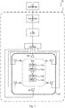
- Fig 1 shows a schematic drawing illustrating an environment being a high-voltage power electronics system 10 in which embodiments presented herein can be applied.
- the high-voltage power electronics system can e.g. be in the form of switchgear, HVDC, and/or FACTS, etc.
- a power equipment controller 11 needs to communicate with one or more power equipment devices 12a-b.
- the power equipment devices 12a-b can e.g. be switches, local controllers, measurement equipment, etc. or any combination or multiple instances of these.
- Each one of the power equipment devices 12a-b communicate using a respective power equipment communication module 13a-b and a corresponding antenna.
- the power equipment devices 12a-b are provided inside an enclosure 16.
- the enclosure 16 can comprise walls, roof and floor and can thus be provided in the form of a building, such as a valve hall.
- a communication device 1 is provided for communicating between the power equipment controller 11 and the power equipment devices 12a-b.
- the communication device 1 is comprises components indicated in Fig 1 between the two dashed lines, except the enclosure 16, which does not form part of the communication device 1.
- the communication device 1 comprises a controller interface 2 for communicating with the power equipment controller 11.
- the controller interface 2 can e.g. be an optical interface, a conductive interface or a wireless interface.
- the controller interface can e.g. based on any suitable Ethernet or IEEE 802.11.x standard, upon which e.g. Internet Protocol (IP) can be used. Alternatively or additionally, custom protocols can be used for low overhead, high performance, communication.
- IP Internet Protocol
- the RF module 3 comprises circuitry for processing RF transmission signals (based on signals provided from the power equipment controller 11) and received RF signals (resulting in signals being provided to the power equipment controller 11).
- An RF splitter 5 is connected to the RF module 3.
- the RF splitter 5 is configured to split RF transmission signals to several corresponding RF antenna signals.
- the RF antenna signals all contain the same RF signals.
- a plurality of antennas 6a-f are configured to transmit a respective one of the RF antenna signals (from the RF splitter) to at least one power equipment device 12a-b.
- the antennas are provided inside the enclosure 16, while the RF module 3 is provided outside the enclosure.
- the use of multiple redundant antennas allows the power equipment devices 12a-b to receive the RF signal from any one of the antennas 6a-f. In this way, reliability of communication is greatly improved.
- the length in time of transmission symbols is long compared with the time it takes for the RF signals to travel between the antennas 6a-f and the power equipment devices 12a-b.
- the redundant antennas 6a-f also make transmissions from the power equipment devices 12a-b more reliable, since it is sufficient that such a transmission is successfully received by one of the redundant antennas 6a-f.
- Fig 2 shows a schematic drawing illustrating one embodiment comprising a plurality of RF modules and a merger. Only differences compared to the embodiment of Fig 1 are described here. Compared to the embodiment of Fig 1 , there are here two RF modules 3a-b. It is to be noted that there can be any number of RF modules in this embodiment.
- Each one of the RF modules 3a-b receives the same data (from the power equipment controller 11) to transmit.
- the RF modules 3a-b are simultaneously active.
- the RF transmission signals differ between different RF modules 3a-b, e.g. by using different communication channels for their RF transmission signals.
- the different communication channels can differ in at least one of frequency, time slots, and encoding. This results in fully redundant transmission of the same data from the power equipment controller 11 using the different RF modules 3a-b.
- An RF merger module 4 is configured to merge RF transmission signals from the RF modules 3a-b in a combined RF signal, and to provide the combined RF signal to the RF splitter 5.
- the merging occurs by multiplexing the transmission signals from the RF modules 3a-b in a single combined RF signal, which works when the differ in at least one of frequency (thus merging using FDMA, Frequency Division Multiple Access), time slots (thus merging using TDMA, Time Division Multiple Access) and encoding (thus merging using CDMA, Code Division Multiple Access).
- all of the antennas 6a-f transmit the same RF signals (as in the embodiment shown in Fig 1 ). Furthermore, the antennas 6a-f are shared by all of the RF modules 3a-b. None of the antennas 6a-f are thus tied to any one (or a subset) of the RF modules 3a-b.
- the RF merger module 4, the RF splitter 5 and the antennas 6a-f are shared by all of the RF modules 3a-.
- the power equipment communication module 13a-b receives only one of these RF transmission signals to receive the data. Successful receipt can be determined e.g. using Cyclic Redundancy Check (CRC).
- CRC Cyclic Redundancy Check
- Using multiple channels sending the same data essentially provides a spatial redundancy, since the propagation (fading) most likely differ for different channels and different paths between antenna and power equipment communication module.
- the other RF module(s) continue to transmit the same data, reducing any issues of the failed RF module.
- one of the RF module(s) 3a-3b is in active mode.
- the other RF module(s) are then in hot stand-by mode and are ready to step in if the active RF module were to fail.
- Fig 3 is a flow chart illustrating a method for communicating in a high-voltage power electronics system. The method is performed in the communication device.
- a communicate with controller step 40 the communication device communicates with the power equipment controller using a controller interface (2 of Fig 1 and Fig 2 ).
- this step comprises receiving data from the power equipment controller for transmission to power equipment and/or providing data received from the power equipment to the power equipment controller.
- the communication device processes RF transmission signals and received RF signals in circuitry of at least one RF module.
- the communication device converts between RF signals and data to/from the power equipment controller.
- the same data is received from the power equipment controller to be transmitted in at least two RF modules.
- the RF transmission signals differ between different RF modules, even though the data content is the same.
- different RF modules can use different communication channels for their RF transmission signals.
- the different communication channels differ in at least one of frequency, time slots, and encoding.
- the communication device merges RF transmission signals from at least two RF modules to a combined RF signal. This step is performed in the RF merger module.
- the communication device provides the combined RF signal to the RF splitter.
- a split step 46 the communication device splits RF transmission signals received from the at least one RF module (optionally via the merge step 44) to several corresponding RF antenna signals. This step is performed in the RF splitter which is connected to the at least one RF module.
- the several corresponding RF antenna signals contain the same RF signals, thus providing transmission redundancy.
- a transmit step 48 the communication device transmits each one of the RF antenna signals to at least one power equipment device using the plurality of antennas.
Landscapes
- Engineering & Computer Science (AREA)
- Computer Networks & Wireless Communication (AREA)
- Signal Processing (AREA)
- Near-Field Transmission Systems (AREA)
- Transmitters (AREA)
Abstract
Description
- The present disclosure relates to the field of radio frequency (RF) communication and in particular to a communication device comprising an RF splitter and a plurality of antennas.
- In traditional high-voltage power electronics systems such as switchgear, HVDC (High Voltage Direct Current), and/or FACTS (Flexible Alternating Current Transmission Systems), etc., the switching of power electronics modules is controlled through wired links, for example optical fibres. Due to the complexity of such systems and the high number of power electronics modules involved, several thousands of cables are often deployed, with a strong impact in structural design, installation and commissioning costs. Moreover, optical fibres being subject to high difference potentials, as it is the case in high-voltage systems, increases risk of flammability. Also, optical transmitters have a much shorter life cycle than power electronics components, with failure rates that can be up to 20 times higher.
- One way to reduce these problems would be to migrate from wired to wireless communication of control signals. However, the environment of a high-voltage power electronics system is very difficult for wireless communication. There are enclosures creating reflections and affecting attenuation. The presence of metal objects causes further signal propagation issues and the switching and high voltage electronic components can cause interference. Field tests have confirmed that the radio propagation environment inside valve halls is much worse than outside.
- Additionally, the communication of control signals in this application is of utmost importance and any failed communication may cause great disruption of the supply of power to large parts of a power grid.
- One objective is to provide wireless communication suitable for use in a high-voltage power electronics system which is more reliable than what is known in the prior art.
- According to a first aspect, it is provided a communication device for communicating between a power equipment controller and power equipment devices of a high-voltage power electronics system. The communication device comprises: a controller interface for communicating with the power equipment controller; at least one RF, radio frequency, module comprising circuitry for processing RF transmission signals and received RF signals; an RF splitter connected to the at least one RF module, the RF splitter being configured to split RF transmission signals received from the at least one RF module to several corresponding RF antenna signals; and a plurality of antennas configured to transmit each one of the RF antenna signals to at least one power equipment device.
- The several corresponding RF antenna signals may contain the same RF signals.
- The communication device may comprise at least two of the RF modules and an RF merger module, in which case the RF merger module is configured to merge RF transmission signals from the at least two RF modules in a combined RF signal, and to provide the combined RF signal to the RF splitter.
- Each one of the at least two RF modules may receive the same data to transmit, in which case the RF transmission signals differ between different RF modules.
- Different RF modules may use different communication channels for their RF transmission signals.
- The different communication channels may differ in at least one of frequency, time slots, and encoding.
- The at least two RF modules may be simultaneously active.
- The plurality of antennas may be configured to be provided inside an enclosure housing the at least one power equipment device while the at least one RF module is configured to be provided outside the enclosure.
- The enclosure may be a valve hall.
- According to a second aspect, it is provided a method for communicating between a power equipment controller and power equipment devices of a high-voltage power electronics system. The method being performed in a communication device and comprises: communicating with the power equipment controller using a controller interface; processing RF, radio frequency, transmission signals and received RF signals in circuitry of at least one RF module; splitting RF transmission signals received from the at least one RF module to several corresponding RF antenna signals in an RF splitter connected to the at least one RF module; and transmitting each one of the RF antenna signals to at least one power equipment device using a plurality of antennas.
- The several corresponding RF antenna signals may contain the same RF signals.
- The method may further comprise the step of: merging RF transmission signals from at least two RF modules in a combined RF signal; and providing the combined RF signal to the RF splitter.
- The step of processing RF transmission signals may comprise receiving the same data to transmit in at least two RF modules, in which case the RF transmission signals differ between different RF modules.
- The step of processing RF transmission different RF modules may use different communication channels for their RF transmission signals.
- The different communication channels may differ in at least one of frequency, time slots, and encoding.
- Generally, all terms used in the claims are to be interpreted according to their ordinary meaning in the technical field, unless explicitly defined otherwise herein. All references to "a/an/the element, apparatus, component, means, step, etc." are to be interpreted openly as referring to at least one instance of the element, apparatus, component, means, step, etc., unless explicitly stated otherwise. The steps of any method disclosed herein do not have to be performed in the exact order disclosed, unless explicitly stated.
- Aspects and embodiments are now described, by way of example, with reference to the accompanying drawings, in which:
-
Fig 1 shows a schematic drawing illustrating an environment in which embodiments presented herein can be applied; -
Fig 2 shows a schematic drawing illustrating one embodiment comprising a plurality of RF modules and a merger; and -
Fig 3 is a flow chart illustrating a method for communicating in a high-voltage power electronics system. - The aspects of the present disclosure will now be described more fully hereinafter with reference to the accompanying drawings, in which certain embodiments of the invention are shown. These aspects may, however, be embodied in many different forms and should not be construed as limiting; rather, these embodiments are provided by way of example so that this disclosure will be thorough and complete, and to fully convey the scope of all aspects of invention to those skilled in the art. Like numbers refer to like elements throughout the description.
-
Fig 1 shows a schematic drawing illustrating an environment being a high-voltagepower electronics system 10 in which embodiments presented herein can be applied. The high-voltage power electronics system can e.g. be in the form of switchgear, HVDC, and/or FACTS, etc. - A
power equipment controller 11 needs to communicate with one or morepower equipment devices 12a-b. Thepower equipment devices 12a-b can e.g. be switches, local controllers, measurement equipment, etc. or any combination or multiple instances of these. Each one of thepower equipment devices 12a-b communicate using a respective powerequipment communication module 13a-b and a corresponding antenna. Thepower equipment devices 12a-b are provided inside anenclosure 16. Theenclosure 16 can comprise walls, roof and floor and can thus be provided in the form of a building, such as a valve hall. - A
communication device 1 is provided for communicating between thepower equipment controller 11 and thepower equipment devices 12a-b. Thecommunication device 1 is comprises components indicated inFig 1 between the two dashed lines, except theenclosure 16, which does not form part of thecommunication device 1. - The
communication device 1 comprises acontroller interface 2 for communicating with thepower equipment controller 11. Thecontroller interface 2 can e.g. be an optical interface, a conductive interface or a wireless interface. The controller interface can e.g. based on any suitable Ethernet or IEEE 802.11.x standard, upon which e.g. Internet Protocol (IP) can be used. Alternatively or additionally, custom protocols can be used for low overhead, high performance, communication. - An RF (radio frequency)
module 3 is provided. TheRF module 3 comprises circuitry for processing RF transmission signals (based on signals provided from the power equipment controller 11) and received RF signals (resulting in signals being provided to the power equipment controller 11). - An
RF splitter 5 is connected to theRF module 3. TheRF splitter 5 is configured to split RF transmission signals to several corresponding RF antenna signals. The RF antenna signals all contain the same RF signals. - A plurality of
antennas 6a-f are configured to transmit a respective one of the RF antenna signals (from the RF splitter) to at least onepower equipment device 12a-b. The antennas are provided inside theenclosure 16, while theRF module 3 is provided outside the enclosure. In the quite difficult RF environment of the high-voltagepower electronics system 10, the use of multiple redundant antennas allows thepower equipment devices 12a-b to receive the RF signal from any one of theantennas 6a-f. In this way, reliability of communication is greatly improved. Moreover, the length in time of transmission symbols is long compared with the time it takes for the RF signals to travel between theantennas 6a-f and thepower equipment devices 12a-b. In this way, signal to noise ratio is improved further by the powerequipment communication modules 13a-b effectively aggregating all signals received. Moreover, since the same RF signals are provided to all of theantennas 6a-f, great redundancy in RF transmissions to thepower equipment device 12a-b is provided. If one of theantennas 6a-f were to fail, communication can proceed without any interruption since all antennas transmit the same RF signals. In other words, a single failed antenna probably does not need to be replaced immediately and can be replaced at the next time there is maintenance in the valve hall. This is of great advantage, since any work inside the valve hall is disruptive. Furthermore, the rate of failure of antennas, splitter and merger is low. - The
redundant antennas 6a-f also make transmissions from thepower equipment devices 12a-b more reliable, since it is sufficient that such a transmission is successfully received by one of theredundant antennas 6a-f. -
Fig 2 shows a schematic drawing illustrating one embodiment comprising a plurality of RF modules and a merger. Only differences compared to the embodiment ofFig 1 are described here. Compared to the embodiment ofFig 1 , there are here twoRF modules 3a-b. It is to be noted that there can be any number of RF modules in this embodiment. - Each one of the
RF modules 3a-b receives the same data (from the power equipment controller 11) to transmit. In one embodiment, theRF modules 3a-b are simultaneously active. In such a case, the RF transmission signals differ betweendifferent RF modules 3a-b, e.g. by using different communication channels for their RF transmission signals. The different communication channels can differ in at least one of frequency, time slots, and encoding. This results in fully redundant transmission of the same data from thepower equipment controller 11 using thedifferent RF modules 3a-b. - An
RF merger module 4 is configured to merge RF transmission signals from theRF modules 3a-b in a combined RF signal, and to provide the combined RF signal to theRF splitter 5. The merging occurs by multiplexing the transmission signals from theRF modules 3a-b in a single combined RF signal, which works when the differ in at least one of frequency (thus merging using FDMA, Frequency Division Multiple Access), time slots (thus merging using TDMA, Time Division Multiple Access) and encoding (thus merging using CDMA, Code Division Multiple Access). - In other words, all of the
antennas 6a-f transmit the same RF signals (as in the embodiment shown inFig 1 ). Furthermore, theantennas 6a-f are shared by all of theRF modules 3a-b. None of theantennas 6a-f are thus tied to any one (or a subset) of theRF modules 3a-b. - Hence, the
RF merger module 4, theRF splitter 5 and theantennas 6a-f are shared by all of theRF modules 3a-. - Since the same data (provided by the power equipment controller 11) forms part of different RF transmission signals, reliability is improved. It is sufficient that the power
equipment communication module 13a-b receives only one of these RF transmission signals to receive the data. Successful receipt can be determined e.g. using Cyclic Redundancy Check (CRC). Using multiple channels sending the same data essentially provides a spatial redundancy, since the propagation (fading) most likely differ for different channels and different paths between antenna and power equipment communication module. Moreover, if one of theRF modules 3a-b were to fail, the other RF module(s) continue to transmit the same data, reducing any issues of the failed RF module. - In one embodiment, one of the RF module(s) 3a-3b is in active mode. The other RF module(s) are then in hot stand-by mode and are ready to step in if the active RF module were to fail.
-
Fig 3 is a flow chart illustrating a method for communicating in a high-voltage power electronics system. The method is performed in the communication device. - In a communicate with
controller step 40, the communication device communicates with the power equipment controller using a controller interface (2 ofFig 1 andFig 2 ). In particular this step comprises receiving data from the power equipment controller for transmission to power equipment and/or providing data received from the power equipment to the power equipment controller. - In a process RF signals step 42, the communication device processes RF transmission signals and received RF signals in circuitry of at least one RF module. In other words, the communication device converts between RF signals and data to/from the power equipment controller. Optionally, the same data is received from the power equipment controller to be transmitted in at least two RF modules. In this case, the RF transmission signals differ between different RF modules, even though the data content is the same. For instance, different RF modules can use different communication channels for their RF transmission signals. The different communication channels differ in at least one of frequency, time slots, and encoding.
- In an
optional merge step 44, the communication device merges RF transmission signals from at least two RF modules to a combined RF signal. This step is performed in the RF merger module. - In an optional provide combined
signal step 45, the communication device provides the combined RF signal to the RF splitter. - In a
split step 46, the communication device splits RF transmission signals received from the at least one RF module (optionally via the merge step 44) to several corresponding RF antenna signals. This step is performed in the RF splitter which is connected to the at least one RF module. The several corresponding RF antenna signals contain the same RF signals, thus providing transmission redundancy. - In a transmit
step 48, the communication device transmits each one of the RF antenna signals to at least one power equipment device using the plurality of antennas. - The aspects of the present disclosure have mainly been described above with reference to a few embodiments. However, as is readily appreciated by a person skilled in the art, other embodiments than the ones disclosed above are equally possible within the scope of the invention, as defined by the appended patent claims. Thus, while various aspects and embodiments have been disclosed herein, other aspects and embodiments will be apparent to those skilled in the art. The various aspects and embodiments disclosed herein are for purposes of illustration and are not intended to be limiting, with the true scope and spirit being indicated by the following claims.
Claims (15)
- A communication device (1) for communicating between a power equipment controller (11) and power equipment devices (12a-b) of a high-voltage power electronics system (10), the communication device (1) comprising:a controller interface (2) for communicating with the power equipment controller (11);at least one RF, radio frequency, module (3, 3a-b) comprising circuitry for processing RF transmission signals and received RF signals;an RF splitter (5) connected to the at least one RF module (3, 3a-b), the RF splitter (5) being configured to split RF transmission signals received from the at least one RF module (3, 3a-b) to several corresponding RF antenna signals; anda plurality of antennas (6a-f) configured to transmit each one of the RF antenna signals to at least one power equipment device (12a-b).
- The communication device (1) according to claim 1, wherein the several corresponding RF antenna signals contain the same RF signals.
- The communication device (1) according to claim 1 or 2, comprising at least two of the RF modules (3, 3a-b) and an RF merger module (4), wherein the RF merger module is configured to merge RF transmission signals from the at least two RF modules (3, 3a-b) in a combined RF signal, and to provide the combined RF signal to the RF splitter (5).
- The communication device (1) according to claim 3, wherein each one of the at least two RF modules (3, 3a-b) receive the same data to transmit, and wherein the RF transmission signals differ between different RF modules (3, 3a-b).
- The communication device (1) according to claim 4, wherein different RF modules (3, 3a-b) use different communication channels for their RF transmission signals.
- The communication device (1) according to claim 5, wherein the different communication channels differ in at least one of frequency, time slots, and encoding.
- The communication device (1) according to any one of claims 3 to 6, wherein the at least two RF modules are simultaneously active.
- The communication device (1) according to any one of the preceding claims, wherein the plurality of antennas are configured to be provided inside an enclosure (16) housing the at least one power equipment device (12a-b) while the at least one RF module (3, 3a-b) is configured to be provided outside the enclosure (16).
- The communication device (1) according to claim 8, wherein the enclosure (16) is a valve hall.
- A method for communicating between a power equipment controller (11) and power equipment devices (12a-b) of a high-voltage power electronics system (10), the method being performed in a communication device (1) and comprising:communicating (40) with the power equipment controller using a controller interface (2);processing (42) RF, radio frequency, transmission signals and received RF signals in circuitry of at least one RF module (3, 3a-b);splitting (46) RF transmission signals received from the at least one RF module (3, 3a-b) to several corresponding RF antenna signals in an RF splitter (5) connected to the at least one RF module (3, 3a-b); andtransmitting (48) each one of the RF antenna signals to at least one power equipment device (12a-b) using a plurality of antennas (6a-f).
- The method according to claim 10, wherein the several corresponding RF antenna signals contain the same RF signals.
- The method according to claim 10 or 11, further comprising the step of:merging (44) RF transmission signals from at least two RF modules (3, 3a-b) in a combined RF signal; andproviding (45) the combined RF signal to the RF splitter (5).
- The method according to claim 12, wherein the step of processing (42) RF transmission signals comprises receiving the same data to transmit in at least two RF modules (3, 3a-b), and wherein the RF transmission signals differ between different RF modules (3, 3a-b).
- The method according to claim 13, wherein the step of processing (42) RF transmission different RF modules (3, 3a-b) use different communication channels for their RF transmission signals.
- The method according to claim 14, wherein the different communication channels differ in at least one of frequency, time slots, and encoding.
Priority Applications (1)
| Application Number | Priority Date | Filing Date | Title |
|---|---|---|---|
| EP19160884.3A EP3706326B1 (en) | 2019-03-05 | 2019-03-05 | Communication device for communicating between a power equipment controller and power equipment devices |
Applications Claiming Priority (1)
| Application Number | Priority Date | Filing Date | Title |
|---|---|---|---|
| EP19160884.3A EP3706326B1 (en) | 2019-03-05 | 2019-03-05 | Communication device for communicating between a power equipment controller and power equipment devices |
Publications (2)
| Publication Number | Publication Date |
|---|---|
| EP3706326A1 true EP3706326A1 (en) | 2020-09-09 |
| EP3706326B1 EP3706326B1 (en) | 2024-02-21 |
Family
ID=65818162
Family Applications (1)
| Application Number | Title | Priority Date | Filing Date |
|---|---|---|---|
| EP19160884.3A Active EP3706326B1 (en) | 2019-03-05 | 2019-03-05 | Communication device for communicating between a power equipment controller and power equipment devices |
Country Status (1)
| Country | Link |
|---|---|
| EP (1) | EP3706326B1 (en) |
Citations (3)
| Publication number | Priority date | Publication date | Assignee | Title |
|---|---|---|---|---|
| US20040121810A1 (en) * | 2002-12-23 | 2004-06-24 | Bo Goransson | Using beamforming and closed loop transmit diversity in a multi-beam antenna system |
| US20140112409A1 (en) * | 2011-06-01 | 2014-04-24 | Hitachi, Ltd. | Wireless Transmitter, Wireless Receiver, Wireless Communication System, Elevator Control System, and Transformer Equipment Control System |
| US20170244457A1 (en) * | 2015-12-13 | 2017-08-24 | Drone Racing League, Inc. | Communication system with distributed receiver architecture |
-
2019
- 2019-03-05 EP EP19160884.3A patent/EP3706326B1/en active Active
Patent Citations (3)
| Publication number | Priority date | Publication date | Assignee | Title |
|---|---|---|---|---|
| US20040121810A1 (en) * | 2002-12-23 | 2004-06-24 | Bo Goransson | Using beamforming and closed loop transmit diversity in a multi-beam antenna system |
| US20140112409A1 (en) * | 2011-06-01 | 2014-04-24 | Hitachi, Ltd. | Wireless Transmitter, Wireless Receiver, Wireless Communication System, Elevator Control System, and Transformer Equipment Control System |
| US20170244457A1 (en) * | 2015-12-13 | 2017-08-24 | Drone Racing League, Inc. | Communication system with distributed receiver architecture |
Also Published As
| Publication number | Publication date |
|---|---|
| EP3706326B1 (en) | 2024-02-21 |
Similar Documents
| Publication | Publication Date | Title |
|---|---|---|
| JP6450764B2 (en) | Method for testing a data packet signal transceiver using interleaved device configuration and testing | |
| US12580636B2 (en) | Selection of decoding level at signal forwarding devices | |
| US9325412B2 (en) | Transceiver system, transmission device, reception device, and control method of transceiver system | |
| KR20160045748A (en) | Method for testing data packet signal transceiver using coordinated transmitted data packet signal power | |
| US10171977B2 (en) | Communication network, a power converter cabinet, and a method therefore | |
| US20050129535A1 (en) | Vacuum pump | |
| CN104581793A (en) | Method and equipment for detecting base-station antenna feed system | |
| WO2017007541A1 (en) | Method for testing a radio frequency (rf) data packet signal transceiver packet error rate | |
| US4949340A (en) | Redundant repeater | |
| US9473391B2 (en) | Protection switching method, system and a node in an LTE network | |
| EP3706326B1 (en) | Communication device for communicating between a power equipment controller and power equipment devices | |
| US10305200B2 (en) | Wireless communication system having a transmission unit that transmits or receives based on a detected timing | |
| EP3560058B1 (en) | System comprising a power electronics element, a control unit, and a communications network for communication between the power electronics element and the control unit. | |
| US20170013602A1 (en) | Method for operating a base station in a wireless radio network, base station and user equipment | |
| KR102162464B1 (en) | Parallel inverter system | |
| US20060234526A1 (en) | Automation system | |
| KR20170089209A (en) | Software safety method based distributed interlocking system | |
| EP3381762B1 (en) | System and method for detecting the presence of a train on a railway track | |
| EP3700095B1 (en) | Reducing interference of a malfunctioning transmitter device | |
| CN104468034B (en) | A kind of transponder transmission host | |
| US20040153705A1 (en) | Data transmission method and device | |
| EP2717168B1 (en) | Networks and method for reliable transfer of information between industrial systems | |
| CN116896696A (en) | Host-based optical frequency tuning | |
| US20230155632A1 (en) | Failsafe Series-Connected Radio System | |
| KR20240170552A (en) | Wireless System |
Legal Events
| Date | Code | Title | Description |
|---|---|---|---|
| PUAI | Public reference made under article 153(3) epc to a published international application that has entered the european phase |
Free format text: ORIGINAL CODE: 0009012 |
|
| STAA | Information on the status of an ep patent application or granted ep patent |
Free format text: STATUS: THE APPLICATION HAS BEEN PUBLISHED |
|
| AK | Designated contracting states |
Kind code of ref document: A1 Designated state(s): AL AT BE BG CH CY CZ DE DK EE ES FI FR GB GR HR HU IE IS IT LI LT LU LV MC MK MT NL NO PL PT RO RS SE SI SK SM TR |
|
| AX | Request for extension of the european patent |
Extension state: BA ME |
|
| STAA | Information on the status of an ep patent application or granted ep patent |
Free format text: STATUS: REQUEST FOR EXAMINATION WAS MADE |
|
| 17P | Request for examination filed |
Effective date: 20210309 |
|
| RBV | Designated contracting states (corrected) |
Designated state(s): AL AT BE BG CH CY CZ DE DK EE ES FI FR GB GR HR HU IE IS IT LI LT LU LV MC MK MT NL NO PL PT RO RS SE SI SK SM TR |
|
| RAP3 | Party data changed (applicant data changed or rights of an application transferred) |
Owner name: HITACHI ENERGY SWITZERLAND AG |
|
| STAA | Information on the status of an ep patent application or granted ep patent |
Free format text: STATUS: EXAMINATION IS IN PROGRESS |
|
| 17Q | First examination report despatched |
Effective date: 20220207 |
|
| P01 | Opt-out of the competence of the unified patent court (upc) registered |
Effective date: 20230527 |
|
| RIC1 | Information provided on ipc code assigned before grant |
Ipc: H04B 1/04 20060101ALN20230720BHEP Ipc: H04B 7/06 20060101ALI20230720BHEP Ipc: H04B 1/74 20060101AFI20230720BHEP |
|
| GRAP | Despatch of communication of intention to grant a patent |
Free format text: ORIGINAL CODE: EPIDOSNIGR1 |
|
| STAA | Information on the status of an ep patent application or granted ep patent |
Free format text: STATUS: GRANT OF PATENT IS INTENDED |
|
| INTG | Intention to grant announced |
Effective date: 20230831 |
|
| GRAJ | Information related to disapproval of communication of intention to grant by the applicant or resumption of examination proceedings by the epo deleted |
Free format text: ORIGINAL CODE: EPIDOSDIGR1 |
|
| STAA | Information on the status of an ep patent application or granted ep patent |
Free format text: STATUS: EXAMINATION IS IN PROGRESS |
|
| GRAP | Despatch of communication of intention to grant a patent |
Free format text: ORIGINAL CODE: EPIDOSNIGR1 |
|
| STAA | Information on the status of an ep patent application or granted ep patent |
Free format text: STATUS: GRANT OF PATENT IS INTENDED |
|
| INTC | Intention to grant announced (deleted) | ||
| INTG | Intention to grant announced |
Effective date: 20231106 |
|
| RIC1 | Information provided on ipc code assigned before grant |
Ipc: H04B 1/04 20060101ALN20231023BHEP Ipc: H04B 7/06 20060101ALI20231023BHEP Ipc: H04B 1/74 20060101AFI20231023BHEP |
|
| RAP1 | Party data changed (applicant data changed or rights of an application transferred) |
Owner name: HITACHI ENERGY LTD |
|
| GRAS | Grant fee paid |
Free format text: ORIGINAL CODE: EPIDOSNIGR3 |
|
| GRAA | (expected) grant |
Free format text: ORIGINAL CODE: 0009210 |
|
| STAA | Information on the status of an ep patent application or granted ep patent |
Free format text: STATUS: THE PATENT HAS BEEN GRANTED |
|
| AK | Designated contracting states |
Kind code of ref document: B1 Designated state(s): AL AT BE BG CH CY CZ DE DK EE ES FI FR GB GR HR HU IE IS IT LI LT LU LV MC MK MT NL NO PL PT RO RS SE SI SK SM TR |
|
| REG | Reference to a national code |
Ref country code: GB Ref legal event code: FG4D |
|
| REG | Reference to a national code |
Ref country code: CH Ref legal event code: EP |
|
| REG | Reference to a national code |
Ref country code: DE Ref legal event code: R096 Ref document number: 602019046775 Country of ref document: DE |
|
| REG | Reference to a national code |
Ref country code: IE Ref legal event code: FG4D |
|
| REG | Reference to a national code |
Ref country code: LT Ref legal event code: MG9D |
|
| REG | Reference to a national code |
Ref country code: NL Ref legal event code: MP Effective date: 20240221 |
|
| PG25 | Lapsed in a contracting state [announced via postgrant information from national office to epo] |
Ref country code: IS Free format text: LAPSE BECAUSE OF FAILURE TO SUBMIT A TRANSLATION OF THE DESCRIPTION OR TO PAY THE FEE WITHIN THE PRESCRIBED TIME-LIMIT Effective date: 20240621 |
|
| PG25 | Lapsed in a contracting state [announced via postgrant information from national office to epo] |
Ref country code: LT Free format text: LAPSE BECAUSE OF FAILURE TO SUBMIT A TRANSLATION OF THE DESCRIPTION OR TO PAY THE FEE WITHIN THE PRESCRIBED TIME-LIMIT Effective date: 20240221 |
|
| PG25 | Lapsed in a contracting state [announced via postgrant information from national office to epo] |
Ref country code: GR Free format text: LAPSE BECAUSE OF FAILURE TO SUBMIT A TRANSLATION OF THE DESCRIPTION OR TO PAY THE FEE WITHIN THE PRESCRIBED TIME-LIMIT Effective date: 20240522 |
|
| REG | Reference to a national code |
Ref country code: AT Ref legal event code: MK05 Ref document number: 1660008 Country of ref document: AT Kind code of ref document: T Effective date: 20240221 |
|
| PG25 | Lapsed in a contracting state [announced via postgrant information from national office to epo] |
Ref country code: HR Free format text: LAPSE BECAUSE OF FAILURE TO SUBMIT A TRANSLATION OF THE DESCRIPTION OR TO PAY THE FEE WITHIN THE PRESCRIBED TIME-LIMIT Effective date: 20240221 Ref country code: RS Free format text: LAPSE BECAUSE OF FAILURE TO SUBMIT A TRANSLATION OF THE DESCRIPTION OR TO PAY THE FEE WITHIN THE PRESCRIBED TIME-LIMIT Effective date: 20240521 Ref country code: NL Free format text: LAPSE BECAUSE OF FAILURE TO SUBMIT A TRANSLATION OF THE DESCRIPTION OR TO PAY THE FEE WITHIN THE PRESCRIBED TIME-LIMIT Effective date: 20240221 |
|
| PG25 | Lapsed in a contracting state [announced via postgrant information from national office to epo] |
Ref country code: ES Free format text: LAPSE BECAUSE OF FAILURE TO SUBMIT A TRANSLATION OF THE DESCRIPTION OR TO PAY THE FEE WITHIN THE PRESCRIBED TIME-LIMIT Effective date: 20240221 |
|
| PG25 | Lapsed in a contracting state [announced via postgrant information from national office to epo] |
Ref country code: AT Free format text: LAPSE BECAUSE OF FAILURE TO SUBMIT A TRANSLATION OF THE DESCRIPTION OR TO PAY THE FEE WITHIN THE PRESCRIBED TIME-LIMIT Effective date: 20240221 |
|
| PG25 | Lapsed in a contracting state [announced via postgrant information from national office to epo] |
Ref country code: RS Free format text: LAPSE BECAUSE OF FAILURE TO SUBMIT A TRANSLATION OF THE DESCRIPTION OR TO PAY THE FEE WITHIN THE PRESCRIBED TIME-LIMIT Effective date: 20240521 Ref country code: NO Free format text: LAPSE BECAUSE OF FAILURE TO SUBMIT A TRANSLATION OF THE DESCRIPTION OR TO PAY THE FEE WITHIN THE PRESCRIBED TIME-LIMIT Effective date: 20240521 Ref country code: NL Free format text: LAPSE BECAUSE OF FAILURE TO SUBMIT A TRANSLATION OF THE DESCRIPTION OR TO PAY THE FEE WITHIN THE PRESCRIBED TIME-LIMIT Effective date: 20240221 Ref country code: LT Free format text: LAPSE BECAUSE OF FAILURE TO SUBMIT A TRANSLATION OF THE DESCRIPTION OR TO PAY THE FEE WITHIN THE PRESCRIBED TIME-LIMIT Effective date: 20240221 Ref country code: IS Free format text: LAPSE BECAUSE OF FAILURE TO SUBMIT A TRANSLATION OF THE DESCRIPTION OR TO PAY THE FEE WITHIN THE PRESCRIBED TIME-LIMIT Effective date: 20240621 Ref country code: HR Free format text: LAPSE BECAUSE OF FAILURE TO SUBMIT A TRANSLATION OF THE DESCRIPTION OR TO PAY THE FEE WITHIN THE PRESCRIBED TIME-LIMIT Effective date: 20240221 Ref country code: GR Free format text: LAPSE BECAUSE OF FAILURE TO SUBMIT A TRANSLATION OF THE DESCRIPTION OR TO PAY THE FEE WITHIN THE PRESCRIBED TIME-LIMIT Effective date: 20240522 Ref country code: FI Free format text: LAPSE BECAUSE OF FAILURE TO SUBMIT A TRANSLATION OF THE DESCRIPTION OR TO PAY THE FEE WITHIN THE PRESCRIBED TIME-LIMIT Effective date: 20240221 Ref country code: ES Free format text: LAPSE BECAUSE OF FAILURE TO SUBMIT A TRANSLATION OF THE DESCRIPTION OR TO PAY THE FEE WITHIN THE PRESCRIBED TIME-LIMIT Effective date: 20240221 Ref country code: BG Free format text: LAPSE BECAUSE OF FAILURE TO SUBMIT A TRANSLATION OF THE DESCRIPTION OR TO PAY THE FEE WITHIN THE PRESCRIBED TIME-LIMIT Effective date: 20240221 Ref country code: AT Free format text: LAPSE BECAUSE OF FAILURE TO SUBMIT A TRANSLATION OF THE DESCRIPTION OR TO PAY THE FEE WITHIN THE PRESCRIBED TIME-LIMIT Effective date: 20240221 |
|
| PG25 | Lapsed in a contracting state [announced via postgrant information from national office to epo] |
Ref country code: PT Free format text: LAPSE BECAUSE OF FAILURE TO SUBMIT A TRANSLATION OF THE DESCRIPTION OR TO PAY THE FEE WITHIN THE PRESCRIBED TIME-LIMIT Effective date: 20240621 Ref country code: PL Free format text: LAPSE BECAUSE OF FAILURE TO SUBMIT A TRANSLATION OF THE DESCRIPTION OR TO PAY THE FEE WITHIN THE PRESCRIBED TIME-LIMIT Effective date: 20240221 |
|
| PG25 | Lapsed in a contracting state [announced via postgrant information from national office to epo] |
Ref country code: SE Free format text: LAPSE BECAUSE OF FAILURE TO SUBMIT A TRANSLATION OF THE DESCRIPTION OR TO PAY THE FEE WITHIN THE PRESCRIBED TIME-LIMIT Effective date: 20240221 Ref country code: PT Free format text: LAPSE BECAUSE OF FAILURE TO SUBMIT A TRANSLATION OF THE DESCRIPTION OR TO PAY THE FEE WITHIN THE PRESCRIBED TIME-LIMIT Effective date: 20240621 Ref country code: PL Free format text: LAPSE BECAUSE OF FAILURE TO SUBMIT A TRANSLATION OF THE DESCRIPTION OR TO PAY THE FEE WITHIN THE PRESCRIBED TIME-LIMIT Effective date: 20240221 Ref country code: LV Free format text: LAPSE BECAUSE OF FAILURE TO SUBMIT A TRANSLATION OF THE DESCRIPTION OR TO PAY THE FEE WITHIN THE PRESCRIBED TIME-LIMIT Effective date: 20240221 |
|
| PG25 | Lapsed in a contracting state [announced via postgrant information from national office to epo] |
Ref country code: DK Free format text: LAPSE BECAUSE OF FAILURE TO SUBMIT A TRANSLATION OF THE DESCRIPTION OR TO PAY THE FEE WITHIN THE PRESCRIBED TIME-LIMIT Effective date: 20240221 |
|
| PG25 | Lapsed in a contracting state [announced via postgrant information from national office to epo] |
Ref country code: SM Free format text: LAPSE BECAUSE OF FAILURE TO SUBMIT A TRANSLATION OF THE DESCRIPTION OR TO PAY THE FEE WITHIN THE PRESCRIBED TIME-LIMIT Effective date: 20240221 |
|
| PG25 | Lapsed in a contracting state [announced via postgrant information from national office to epo] |
Ref country code: CZ Free format text: LAPSE BECAUSE OF FAILURE TO SUBMIT A TRANSLATION OF THE DESCRIPTION OR TO PAY THE FEE WITHIN THE PRESCRIBED TIME-LIMIT Effective date: 20240221 Ref country code: EE Free format text: LAPSE BECAUSE OF FAILURE TO SUBMIT A TRANSLATION OF THE DESCRIPTION OR TO PAY THE FEE WITHIN THE PRESCRIBED TIME-LIMIT Effective date: 20240221 |
|
| PG25 | Lapsed in a contracting state [announced via postgrant information from national office to epo] |
Ref country code: SK Free format text: LAPSE BECAUSE OF FAILURE TO SUBMIT A TRANSLATION OF THE DESCRIPTION OR TO PAY THE FEE WITHIN THE PRESCRIBED TIME-LIMIT Effective date: 20240221 |
|
| PG25 | Lapsed in a contracting state [announced via postgrant information from national office to epo] |
Ref country code: SM Free format text: LAPSE BECAUSE OF FAILURE TO SUBMIT A TRANSLATION OF THE DESCRIPTION OR TO PAY THE FEE WITHIN THE PRESCRIBED TIME-LIMIT Effective date: 20240221 Ref country code: SK Free format text: LAPSE BECAUSE OF FAILURE TO SUBMIT A TRANSLATION OF THE DESCRIPTION OR TO PAY THE FEE WITHIN THE PRESCRIBED TIME-LIMIT Effective date: 20240221 Ref country code: RO Free format text: LAPSE BECAUSE OF FAILURE TO SUBMIT A TRANSLATION OF THE DESCRIPTION OR TO PAY THE FEE WITHIN THE PRESCRIBED TIME-LIMIT Effective date: 20240221 Ref country code: EE Free format text: LAPSE BECAUSE OF FAILURE TO SUBMIT A TRANSLATION OF THE DESCRIPTION OR TO PAY THE FEE WITHIN THE PRESCRIBED TIME-LIMIT Effective date: 20240221 Ref country code: DK Free format text: LAPSE BECAUSE OF FAILURE TO SUBMIT A TRANSLATION OF THE DESCRIPTION OR TO PAY THE FEE WITHIN THE PRESCRIBED TIME-LIMIT Effective date: 20240221 Ref country code: CZ Free format text: LAPSE BECAUSE OF FAILURE TO SUBMIT A TRANSLATION OF THE DESCRIPTION OR TO PAY THE FEE WITHIN THE PRESCRIBED TIME-LIMIT Effective date: 20240221 |
|
| REG | Reference to a national code |
Ref country code: CH Ref legal event code: PL |
|
| PG25 | Lapsed in a contracting state [announced via postgrant information from national office to epo] |
Ref country code: LU Free format text: LAPSE BECAUSE OF NON-PAYMENT OF DUE FEES Effective date: 20240305 |
|
| PG25 | Lapsed in a contracting state [announced via postgrant information from national office to epo] |
Ref country code: MC Free format text: LAPSE BECAUSE OF FAILURE TO SUBMIT A TRANSLATION OF THE DESCRIPTION OR TO PAY THE FEE WITHIN THE PRESCRIBED TIME-LIMIT Effective date: 20240221 |
|
| REG | Reference to a national code |
Ref country code: DE Ref legal event code: R097 Ref document number: 602019046775 Country of ref document: DE |
|
| PG25 | Lapsed in a contracting state [announced via postgrant information from national office to epo] |
Ref country code: MC Free format text: LAPSE BECAUSE OF FAILURE TO SUBMIT A TRANSLATION OF THE DESCRIPTION OR TO PAY THE FEE WITHIN THE PRESCRIBED TIME-LIMIT Effective date: 20240221 Ref country code: LU Free format text: LAPSE BECAUSE OF NON-PAYMENT OF DUE FEES Effective date: 20240305 |
|
| PG25 | Lapsed in a contracting state [announced via postgrant information from national office to epo] |
Ref country code: IT Free format text: LAPSE BECAUSE OF FAILURE TO SUBMIT A TRANSLATION OF THE DESCRIPTION OR TO PAY THE FEE WITHIN THE PRESCRIBED TIME-LIMIT Effective date: 20240221 |
|
| REG | Reference to a national code |
Ref country code: BE Ref legal event code: MM Effective date: 20240331 |
|
| PLBE | No opposition filed within time limit |
Free format text: ORIGINAL CODE: 0009261 |
|
| STAA | Information on the status of an ep patent application or granted ep patent |
Free format text: STATUS: NO OPPOSITION FILED WITHIN TIME LIMIT |
|
| PG25 | Lapsed in a contracting state [announced via postgrant information from national office to epo] |
Ref country code: IT Free format text: LAPSE BECAUSE OF FAILURE TO SUBMIT A TRANSLATION OF THE DESCRIPTION OR TO PAY THE FEE WITHIN THE PRESCRIBED TIME-LIMIT Effective date: 20240221 |
|
| PG25 | Lapsed in a contracting state [announced via postgrant information from national office to epo] |
Ref country code: BE Free format text: LAPSE BECAUSE OF NON-PAYMENT OF DUE FEES Effective date: 20240331 |
|
| PG25 | Lapsed in a contracting state [announced via postgrant information from national office to epo] |
Ref country code: IE Free format text: LAPSE BECAUSE OF NON-PAYMENT OF DUE FEES Effective date: 20240305 |
|
| 26N | No opposition filed |
Effective date: 20241122 |
|
| PG25 | Lapsed in a contracting state [announced via postgrant information from national office to epo] |
Ref country code: IE Free format text: LAPSE BECAUSE OF NON-PAYMENT OF DUE FEES Effective date: 20240305 Ref country code: BE Free format text: LAPSE BECAUSE OF NON-PAYMENT OF DUE FEES Effective date: 20240331 Ref country code: CH Free format text: LAPSE BECAUSE OF NON-PAYMENT OF DUE FEES Effective date: 20240331 |
|
| PG25 | Lapsed in a contracting state [announced via postgrant information from national office to epo] |
Ref country code: SI Free format text: LAPSE BECAUSE OF FAILURE TO SUBMIT A TRANSLATION OF THE DESCRIPTION OR TO PAY THE FEE WITHIN THE PRESCRIBED TIME-LIMIT Effective date: 20240221 |
|
| PG25 | Lapsed in a contracting state [announced via postgrant information from national office to epo] |
Ref country code: CY Free format text: LAPSE BECAUSE OF FAILURE TO SUBMIT A TRANSLATION OF THE DESCRIPTION OR TO PAY THE FEE WITHIN THE PRESCRIBED TIME-LIMIT; INVALID AB INITIO Effective date: 20190305 |
|
| PG25 | Lapsed in a contracting state [announced via postgrant information from national office to epo] |
Ref country code: HU Free format text: LAPSE BECAUSE OF FAILURE TO SUBMIT A TRANSLATION OF THE DESCRIPTION OR TO PAY THE FEE WITHIN THE PRESCRIBED TIME-LIMIT; INVALID AB INITIO Effective date: 20190305 |
|
| PG25 | Lapsed in a contracting state [announced via postgrant information from national office to epo] |
Ref country code: TR Free format text: LAPSE BECAUSE OF FAILURE TO SUBMIT A TRANSLATION OF THE DESCRIPTION OR TO PAY THE FEE WITHIN THE PRESCRIBED TIME-LIMIT Effective date: 20240221 |
|
| PGFP | Annual fee paid to national office [announced via postgrant information from national office to epo] |
Ref country code: GB Payment date: 20260324 Year of fee payment: 8 |
|
| PGFP | Annual fee paid to national office [announced via postgrant information from national office to epo] |
Ref country code: DE Payment date: 20260319 Year of fee payment: 8 |
|
| PGFP | Annual fee paid to national office [announced via postgrant information from national office to epo] |
Ref country code: FR Payment date: 20260320 Year of fee payment: 8 |