EP3706201A1 - Connection for an electrolyser stack, suitable for explosive atmospheres - Google Patents
Connection for an electrolyser stack, suitable for explosive atmospheres Download PDFInfo
- Publication number
- EP3706201A1 EP3706201A1 EP17905037.2A EP17905037A EP3706201A1 EP 3706201 A1 EP3706201 A1 EP 3706201A1 EP 17905037 A EP17905037 A EP 17905037A EP 3706201 A1 EP3706201 A1 EP 3706201A1
- Authority
- EP
- European Patent Office
- Prior art keywords
- stack
- connection
- terminals
- extensions
- box
- Prior art date
- Legal status (The legal status is an assumption and is not a legal conclusion. Google has not performed a legal analysis and makes no representation as to the accuracy of the status listed.)
- Pending
Links
- 239000002360 explosive Substances 0.000 title claims abstract description 14
- 238000005868 electrolysis reaction Methods 0.000 claims abstract description 9
- 239000011347 resin Substances 0.000 claims abstract description 4
- 229920005989 resin Polymers 0.000 claims abstract description 4
- 239000001257 hydrogen Substances 0.000 description 6
- 229910052739 hydrogen Inorganic materials 0.000 description 6
- UFHFLCQGNIYNRP-UHFFFAOYSA-N Hydrogen Chemical compound [H][H] UFHFLCQGNIYNRP-UHFFFAOYSA-N 0.000 description 4
- 238000004880 explosion Methods 0.000 description 4
- XLYOFNOQVPJJNP-UHFFFAOYSA-N water Substances O XLYOFNOQVPJJNP-UHFFFAOYSA-N 0.000 description 4
- QVGXLLKOCUKJST-UHFFFAOYSA-N atomic oxygen Chemical compound [O] QVGXLLKOCUKJST-UHFFFAOYSA-N 0.000 description 3
- 239000001301 oxygen Substances 0.000 description 3
- 229910052760 oxygen Inorganic materials 0.000 description 3
- 231100001261 hazardous Toxicity 0.000 description 2
- 150000002431 hydrogen Chemical class 0.000 description 2
- 239000000654 additive Substances 0.000 description 1
- 230000000295 complement effect Effects 0.000 description 1
- 239000000463 material Substances 0.000 description 1
- 239000002184 metal Substances 0.000 description 1
- 238000000034 method Methods 0.000 description 1
- 238000007789 sealing Methods 0.000 description 1
Images

Classifications
-
- C—CHEMISTRY; METALLURGY
- C25—ELECTROLYTIC OR ELECTROPHORETIC PROCESSES; APPARATUS THEREFOR
- C25B—ELECTROLYTIC OR ELECTROPHORETIC PROCESSES FOR THE PRODUCTION OF COMPOUNDS OR NON-METALS; APPARATUS THEREFOR
- C25B1/00—Electrolytic production of inorganic compounds or non-metals
- C25B1/01—Products
- C25B1/02—Hydrogen or oxygen
- C25B1/04—Hydrogen or oxygen by electrolysis of water
-
- C—CHEMISTRY; METALLURGY
- C25—ELECTROLYTIC OR ELECTROPHORETIC PROCESSES; APPARATUS THEREFOR
- C25B—ELECTROLYTIC OR ELECTROPHORETIC PROCESSES FOR THE PRODUCTION OF COMPOUNDS OR NON-METALS; APPARATUS THEREFOR
- C25B9/00—Cells or assemblies of cells; Constructional parts of cells; Assemblies of constructional parts, e.g. electrode-diaphragm assemblies; Process-related cell features
- C25B9/60—Constructional parts of cells
- C25B9/65—Means for supplying current; Electrode connections; Electric inter-cell connections
-
- H—ELECTRICITY
- H01—ELECTRIC ELEMENTS
- H01M—PROCESSES OR MEANS, e.g. BATTERIES, FOR THE DIRECT CONVERSION OF CHEMICAL ENERGY INTO ELECTRICAL ENERGY
- H01M50/00—Constructional details or processes of manufacture of the non-active parts of electrochemical cells other than fuel cells, e.g. hybrid cells
- H01M50/50—Current conducting connections for cells or batteries
- H01M50/528—Fixed electrical connections, i.e. not intended for disconnection
-
- Y—GENERAL TAGGING OF NEW TECHNOLOGICAL DEVELOPMENTS; GENERAL TAGGING OF CROSS-SECTIONAL TECHNOLOGIES SPANNING OVER SEVERAL SECTIONS OF THE IPC; TECHNICAL SUBJECTS COVERED BY FORMER USPC CROSS-REFERENCE ART COLLECTIONS [XRACs] AND DIGESTS
- Y02—TECHNOLOGIES OR APPLICATIONS FOR MITIGATION OR ADAPTATION AGAINST CLIMATE CHANGE
- Y02E—REDUCTION OF GREENHOUSE GAS [GHG] EMISSIONS, RELATED TO ENERGY GENERATION, TRANSMISSION OR DISTRIBUTION
- Y02E60/00—Enabling technologies; Technologies with a potential or indirect contribution to GHG emissions mitigation
- Y02E60/10—Energy storage using batteries
-
- Y—GENERAL TAGGING OF NEW TECHNOLOGICAL DEVELOPMENTS; GENERAL TAGGING OF CROSS-SECTIONAL TECHNOLOGIES SPANNING OVER SEVERAL SECTIONS OF THE IPC; TECHNICAL SUBJECTS COVERED BY FORMER USPC CROSS-REFERENCE ART COLLECTIONS [XRACs] AND DIGESTS
- Y02—TECHNOLOGIES OR APPLICATIONS FOR MITIGATION OR ADAPTATION AGAINST CLIMATE CHANGE
- Y02E—REDUCTION OF GREENHOUSE GAS [GHG] EMISSIONS, RELATED TO ENERGY GENERATION, TRANSMISSION OR DISTRIBUTION
- Y02E60/00—Enabling technologies; Technologies with a potential or indirect contribution to GHG emissions mitigation
- Y02E60/30—Hydrogen technology
- Y02E60/36—Hydrogen production from non-carbon containing sources, e.g. by water electrolysis
Definitions
- the present invention relates to an electrical connection for an electrolyser stack, suitable for explosive atmosphere.
- An electrolyser is a system that breaks down water molecules by electrolysis to produce hydrogen and oxygen.
- the electrical connection of an electrolysis stack is characterised by ensuring an efficient protection against potential explosions that may occur due to the atmosphere in which it is located.
- the present invention belongs to the field of electrolysers, more specifically electrolysis stacks, as well as to the field of connection boxes.
- the stack is the part of an electrolyser where the water molecule is decomposed into hydrogen and oxygen. Water and a direct current flow through these devices resulting in the production of oxygen and hydrogen at the output thereof.
- the nature of these devices (hydrogen producers) and the location thereof makes them be classified as hazardous, and must therefore be considered as suitable for explosive atmospheres (ATEX).
- these devices currently comprise two metal plates, one for the negative terminal and another one for the positive terminal. These terminals have a perforated end to allow connection by screws, while on the other end the terminal is connected to the cable or busbars, depending on the power of the stack.
- UNE Standard UNE-60079-10-1 which is a translation of international Standard IEC 60079-10-1, indicates that the safety principle that must be followed is eliminating the likelihood that a gaseous explosive atmosphere is present around an ignition source, and if it is not possible to ensure a null probability it is preferable to remove the ignition source.
- the aim of the present invention is to eliminate the probability of an explosion due to the presence of an explosive atmosphere in combination with electrical connections that can generate sparks, developing a connection as described below, the essence of which is indicated in claim one.
- the aim of the present invention is to develop an electrical connection for an electrolysis stack that minimises the likelihood of causing an explosion due to the joint presence of an explosive atmosphere and an ignition source caused by the electrical connection itself.
- connection that is the subject matter of the invention comprises extensions of the stack terminals, a connection box which in one possible embodiment comprises means for attachment to the stack; the connection box has a sealed inlet for the stack extensions and another sealed inlet for the connection terminals from the power supply.
- the extensions of the stack terminals shall be designed such as to allow bringing said extensions near each other.
- the sealing of the terminals in their inlet to the connection box can be provided by an insulating resin or any other functionally equivalent element.
- connection between the stack terminals and the outlet terminals takes place inside the connection box by any known means.
- connection of the terminals to take place in an environment that prevents contact with an explosive atmosphere, such as in the presence of hydrogen, of the sparks that may occur in the connection between the plates.
- Figure 1 shows that the connection of the invention comprises:
- the extensions (3) can have any shape or configuration and are meant to separate the explosive atmosphere from the connections. In addition, these extensions also allow bringing the stack terminals (2) closer to each other when they are very separated, as is the case when the stack is large.
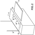
- connection box (4) Among the possible means for attaching the connection box (4) to the stack are securing bars (6) which are arranged at an angle to hold the connection box (4) on the stack.
- the sealed inlets (5) of the connection box (4) can be provided by the use of insulating resins.
- connection box (4) which is suitable for explosive environments.
Landscapes
- Chemical & Material Sciences (AREA)
- Chemical Kinetics & Catalysis (AREA)
- Electrochemistry (AREA)
- Engineering & Computer Science (AREA)
- Materials Engineering (AREA)
- Metallurgy (AREA)
- Organic Chemistry (AREA)
- General Chemical & Material Sciences (AREA)
- Inorganic Chemistry (AREA)
- Connection Or Junction Boxes (AREA)
- Electrolytic Production Of Non-Metals, Compounds, Apparatuses Therefor (AREA)
Abstract
Description
- As indicated by its title, the present invention relates to an electrical connection for an electrolyser stack, suitable for explosive atmosphere. An electrolyser is a system that breaks down water molecules by electrolysis to produce hydrogen and oxygen.
- The electrical connection of an electrolysis stack is characterised by ensuring an efficient protection against potential explosions that may occur due to the atmosphere in which it is located.
- Therefore, the present invention belongs to the field of electrolysers, more specifically electrolysis stacks, as well as to the field of connection boxes.
- The stack is the part of an electrolyser where the water molecule is decomposed into hydrogen and oxygen. Water and a direct current flow through these devices resulting in the production of oxygen and hydrogen at the output thereof. The nature of these devices (hydrogen producers) and the location thereof makes them be classified as hazardous, and must therefore be considered as suitable for explosive atmospheres (ATEX).
- This is problematic for these devices, as their electrical connections do not meet the minimum requirements for safe use in areas with this classification.
- As they use direct current, these devices currently comprise two metal plates, one for the negative terminal and another one for the positive terminal. These terminals have a perforated end to allow connection by screws, while on the other end the terminal is connected to the cable or busbars, depending on the power of the stack.
- The mere connection of these devices is hazardous itself, as during operation thereof when electric current is applied and water passes through the stack, vibrations occur that over time make the electrical connections looser than they were initially. Consequently, this can lead to sparks forming which, in contact with hydrogen, could cause an explosion.
- Moreover, UNE Standard UNE-60079-10-1, which is a translation of international Standard IEC 60079-10-1, indicates that the safety principle that must be followed is eliminating the likelihood that a gaseous explosive atmosphere is present around an ignition source, and if it is not possible to ensure a null probability it is preferable to remove the ignition source.
- Therefore, the aim of the present invention is to eliminate the probability of an explosion due to the presence of an explosive atmosphere in combination with electrical connections that can generate sparks, developing a connection as described below, the essence of which is indicated in claim one.
- The aim of the present invention is to develop an electrical connection for an electrolysis stack that minimises the likelihood of causing an explosion due to the joint presence of an explosive atmosphere and an ignition source caused by the electrical connection itself.
- The connection that is the subject matter of the invention comprises extensions of the stack terminals, a connection box which in one possible embodiment comprises means for attachment to the stack; the connection box has a sealed inlet for the stack extensions and another sealed inlet for the connection terminals from the power supply.
- If the stack terminals are separated, such as due to the size of the stack, the extensions of the stack terminals shall be designed such as to allow bringing said extensions near each other.
- The sealing of the terminals in their inlet to the connection box can be provided by an insulating resin or any other functionally equivalent element.
- The connection between the stack terminals and the outlet terminals takes place inside the connection box by any known means.
- The features described above allow the connection of the terminals to take place in an environment that prevents contact with an explosive atmosphere, such as in the presence of hydrogen, of the sparks that may occur in the connection between the plates.
- Unless indicated otherwise, all the technical and scientific elements used in this specification have the meaning usually understood by a person skilled in the art to which this invention belongs. In the practice of this invention, methods and materials similar or equivalent to those described in the specification may be used.
- In the description and claims, the word "comprises" and its variants do not intend to exclude other technical characteristics, additives, components or steps. For persons skilled in the art, other objects, advantages and characteristics of the invention will be partly inferred from the description and partly from the practice of the invention.
- To complement the present description, and to help to better understand the characteristics of the invention according to a preferred practical embodiment thereof, the said description is accompanied, as an integral part thereof, by a set of drawings wherein the following has been represented in an illustrative and non-limiting manner:
-
Figure 1 shows a general view of the connection between the terminals of an electrolysis stack and the output terminals. -
Figure 2 shows an enlarged view of the connection box used in the connection. - In view of the figures, a preferred embodiment of the proposed invention is described below.
-
Figure 1 shows that the connection of the invention comprises: - extensions (3) of the connection terminals (2) of a stack (1)
- a connection box (4) in which the extensions (3) of the terminals (2) are connected to the output terminals (7), both terminals passing through sealed inlets (5) appropriate for use in explosive atmospheres.
- means for attaching the connection box (4) to the stack.
- The extensions (3) can have any shape or configuration and are meant to separate the explosive atmosphere from the connections. In addition, these extensions also allow bringing the stack terminals (2) closer to each other when they are very separated, as is the case when the stack is large.
- Among the possible means for attaching the connection box (4) to the stack are securing bars (6) which are arranged at an angle to hold the connection box (4) on the stack.
- The sealed inlets (5) of the connection box (4) can be provided by the use of insulating resins.
- The connection between the two terminals, the terminals (2) of the stack (1) and the output terminals (7), occurs inside the connection box (4), which is suitable for explosive environments.
- Having sufficiently described the nature of the present invention, in addition to the manner in which to put it into practice, it is hereby stated that, in its essence, it may be put into practice in other embodiments that differ in detail from that indicated by way of example, and to which the protection equally applies, provided that its main principle is not altered, changed or modified.
Claims (3)
- Electrical connection of an electrolysis stack suitable for explosive atmospheres, characterised in that it comprises:- extensions (3) of the connection terminals (2) of a stack (1)- - a connection box (4) in which the extensions (3) of the terminals (2) are connected to output terminals (7), both terminals passing through sealed inlets (5)- means for attaching the connection box (4) to the stack.
- Electrical connection of an electrolysis stack suitable for explosive atmospheres according to claim 1, characterised in that the sealed inlets (5) use insulating resins.
- Electrical connection of an electrolysis stack suitable for explosive atmospheres according to claim 1 or 2, characterised in that the means for attaching the connection box to the stack comprise securing bars (6) which are arranged at an angle to hold the connections box (4) on the stack.
Applications Claiming Priority (1)
| Application Number | Priority Date | Filing Date | Title |
|---|---|---|---|
| PCT/ES2017/070301 WO2018189410A1 (en) | 2017-05-12 | 2017-05-12 | Connection for an electrolyser stack, suitable for explosive atmospheres |
Publications (2)
| Publication Number | Publication Date |
|---|---|
| EP3706201A1 true EP3706201A1 (en) | 2020-09-09 |
| EP3706201A4 EP3706201A4 (en) | 2021-01-20 |
Family
ID=63792898
Family Applications (1)
| Application Number | Title | Priority Date | Filing Date |
|---|---|---|---|
| EP17905037.2A Pending EP3706201A4 (en) | 2017-05-12 | 2017-05-12 | Connection for an electrolyser stack, suitable for explosive atmospheres |
Country Status (2)
| Country | Link |
|---|---|
| EP (1) | EP3706201A4 (en) |
| WO (1) | WO2018189410A1 (en) |
Family Cites Families (8)
| Publication number | Priority date | Publication date | Assignee | Title |
|---|---|---|---|---|
| ZA796702B (en) * | 1978-12-16 | 1980-11-26 | Lucas Industries Ltd | Electric storage batteries |
| EP1473386A4 (en) * | 2002-01-29 | 2005-04-06 | Mitsubishi Corp | APPARATUS FOR PRODUCING HIGH PRESSURE HYDROGEN AND PROCESS FOR PRODUCING THE SAME |
| GB0216828D0 (en) * | 2002-07-19 | 2002-08-28 | Boc Group Plc | Apparatus and method for fluorine production |
| CA2534420A1 (en) * | 2006-01-27 | 2007-07-27 | Hy-Drive Technologies Ltd. | Systems to reduce vibration damage in hydrogen generating apparatus |
| CN101445940B (en) * | 2008-12-15 | 2011-05-04 | 李绅洋有限公司 | An energy-saving device and method for generating hydrogen-oxygen combustion-supporting gas |
| ITTO20121043A1 (en) * | 2012-12-05 | 2014-06-06 | Comelec S R L | ELECTRICAL CONNECTOR FOR A APPLIANCE COMBUSTIBLE GAS CONSUMPTION METER |
| FR3002953A1 (en) * | 2013-03-08 | 2014-09-12 | Ceram Hyd | MODULAR COUPLING ASSEMBLY OF ELECTROCHEMICAL UNITS |
| CN103789784B (en) * | 2013-11-28 | 2017-03-01 | 林信涌 | Modularity health care gas generator |
-
2017
- 2017-05-12 EP EP17905037.2A patent/EP3706201A4/en active Pending
- 2017-05-12 WO PCT/ES2017/070301 patent/WO2018189410A1/en not_active Ceased
Also Published As
| Publication number | Publication date |
|---|---|
| EP3706201A4 (en) | 2021-01-20 |
| WO2018189410A1 (en) | 2018-10-18 |
Similar Documents
| Publication | Publication Date | Title |
|---|---|---|
| EP2495746A1 (en) | Subsea fuse assembly | |
| CN109787138A (en) | Isolation and exhaust system for electrical enclosure | |
| EP3016128A1 (en) | Subsea fuse assembly | |
| EP3706201A1 (en) | Connection for an electrolyser stack, suitable for explosive atmospheres | |
| CN104158338A (en) | Explosion-suppression-type motor junction box structure | |
| CN101789645B (en) | Flameproof junction box of motor stator | |
| US1469034A (en) | Electric-lighting device | |
| CN202662499U (en) | Mining explosion-proof control button | |
| EP2727123A2 (en) | Moulded electrotechnical protection component | |
| CN205232603U (en) | Group of electrical apparatus for explosive atmospheres switch board | |
| CN212182888U (en) | High explosion-proof case of security | |
| CN206401840U (en) | Explosion-proof bank electricity power connection equipment | |
| CN201910586U (en) | Explosion-proof device for mining intrinsically-safe power supply | |
| CN204992462U (en) | Mine -used flameproof low pressure cable connection box | |
| US416144A (en) | Bror hemming wesslau | |
| US1108350A (en) | Electric conductor. | |
| CN205016604U (en) | Novel explosion -proof battery box | |
| CN205278516U (en) | Valve electric actuator's blast resistant construction | |
| CN203940062U (en) | Explosion-proof electrification pressure relief system | |
| US20190058324A1 (en) | Circuit forming method and hydrogen station | |
| CN103855484A (en) | Flameproof type fixed insulating bus | |
| CN109412314A (en) | A kind of explosion-proof electric machine | |
| CN202455682U (en) | Electrical appliance for O area in dangerous area | |
| CN201733158U (en) | Explosion-proof three-phase asynchronous motor | |
| CN203951117U (en) | A kind of mining terminal box |
Legal Events
| Date | Code | Title | Description |
|---|---|---|---|
| STAA | Information on the status of an ep patent application or granted ep patent |
Free format text: STATUS: THE INTERNATIONAL PUBLICATION HAS BEEN MADE |
|
| PUAI | Public reference made under article 153(3) epc to a published international application that has entered the european phase |
Free format text: ORIGINAL CODE: 0009012 |
|
| STAA | Information on the status of an ep patent application or granted ep patent |
Free format text: STATUS: REQUEST FOR EXAMINATION WAS MADE |
|
| 17P | Request for examination filed |
Effective date: 20200312 |
|
| AK | Designated contracting states |
Kind code of ref document: A1 Designated state(s): AL AT BE BG CH CY CZ DE DK EE ES FI FR GB GR HR HU IE IS IT LI LT LU LV MC MK MT NL NO PL PT RO RS SE SI SK SM TR |
|
| A4 | Supplementary search report drawn up and despatched |
Effective date: 20201222 |
|
| RIC1 | Information provided on ipc code assigned before grant |
Ipc: C25B 1/04 20060101ALI20201216BHEP Ipc: C25B 9/04 20060101ALI20201216BHEP Ipc: H01R 13/52 20060101ALI20201216BHEP Ipc: H01M 2/22 20060101AFI20201216BHEP |
|
| P01 | Opt-out of the competence of the unified patent court (upc) registered |
Effective date: 20230601 |
|
| STAA | Information on the status of an ep patent application or granted ep patent |
Free format text: STATUS: EXAMINATION IS IN PROGRESS |
|
| 17Q | First examination report despatched |
Effective date: 20230725 |