EP3706199A1 - Separator for rechargeable lithium battery and rechargeable lithium battery including the same - Google Patents
Separator for rechargeable lithium battery and rechargeable lithium battery including the same Download PDFInfo
- Publication number
- EP3706199A1 EP3706199A1 EP20160978.1A EP20160978A EP3706199A1 EP 3706199 A1 EP3706199 A1 EP 3706199A1 EP 20160978 A EP20160978 A EP 20160978A EP 3706199 A1 EP3706199 A1 EP 3706199A1
- Authority
- EP
- European Patent Office
- Prior art keywords
- separator
- polyurethane
- weight
- binder
- cross
- Prior art date
- Legal status (The legal status is an assumption and is not a legal conclusion. Google has not performed a legal analysis and makes no representation as to the accuracy of the status listed.)
- Granted
Links
Images

Classifications
-
- C—CHEMISTRY; METALLURGY
- C09—DYES; PAINTS; POLISHES; NATURAL RESINS; ADHESIVES; COMPOSITIONS NOT OTHERWISE PROVIDED FOR; APPLICATIONS OF MATERIALS NOT OTHERWISE PROVIDED FOR
- C09D—COATING COMPOSITIONS, e.g. PAINTS, VARNISHES OR LACQUERS; FILLING PASTES; CHEMICAL PAINT OR INK REMOVERS; INKS; CORRECTING FLUIDS; WOODSTAINS; PASTES OR SOLIDS FOR COLOURING OR PRINTING; USE OF MATERIALS THEREFOR
- C09D7/00—Features of coating compositions, not provided for in group C09D5/00; Processes for incorporating ingredients in coating compositions
- C09D7/40—Additives
- C09D7/60—Additives non-macromolecular
- C09D7/61—Additives non-macromolecular inorganic
-
- H—ELECTRICITY
- H01—ELECTRIC ELEMENTS
- H01M—PROCESSES OR MEANS, e.g. BATTERIES, FOR THE DIRECT CONVERSION OF CHEMICAL ENERGY INTO ELECTRICAL ENERGY
- H01M10/00—Secondary cells; Manufacture thereof
- H01M10/05—Accumulators with non-aqueous electrolyte
- H01M10/052—Li-accumulators
-
- C—CHEMISTRY; METALLURGY
- C09—DYES; PAINTS; POLISHES; NATURAL RESINS; ADHESIVES; COMPOSITIONS NOT OTHERWISE PROVIDED FOR; APPLICATIONS OF MATERIALS NOT OTHERWISE PROVIDED FOR
- C09D—COATING COMPOSITIONS, e.g. PAINTS, VARNISHES OR LACQUERS; FILLING PASTES; CHEMICAL PAINT OR INK REMOVERS; INKS; CORRECTING FLUIDS; WOODSTAINS; PASTES OR SOLIDS FOR COLOURING OR PRINTING; USE OF MATERIALS THEREFOR
- C09D175/00—Coating compositions based on polyureas or polyurethanes; Coating compositions based on derivatives of such polymers
- C09D175/04—Polyurethanes
- C09D175/08—Polyurethanes from polyethers
-
- H—ELECTRICITY
- H01—ELECTRIC ELEMENTS
- H01M—PROCESSES OR MEANS, e.g. BATTERIES, FOR THE DIRECT CONVERSION OF CHEMICAL ENERGY INTO ELECTRICAL ENERGY
- H01M50/00—Constructional details or processes of manufacture of the non-active parts of electrochemical cells other than fuel cells, e.g. hybrid cells
- H01M50/40—Separators; Membranes; Diaphragms; Spacing elements inside cells
- H01M50/409—Separators, membranes or diaphragms characterised by the material
- H01M50/411—Organic material
-
- H—ELECTRICITY
- H01—ELECTRIC ELEMENTS
- H01M—PROCESSES OR MEANS, e.g. BATTERIES, FOR THE DIRECT CONVERSION OF CHEMICAL ENERGY INTO ELECTRICAL ENERGY
- H01M50/00—Constructional details or processes of manufacture of the non-active parts of electrochemical cells other than fuel cells, e.g. hybrid cells
- H01M50/40—Separators; Membranes; Diaphragms; Spacing elements inside cells
- H01M50/409—Separators, membranes or diaphragms characterised by the material
- H01M50/411—Organic material
- H01M50/414—Synthetic resins, e.g. thermoplastics or thermosetting resins
-
- H—ELECTRICITY
- H01—ELECTRIC ELEMENTS
- H01M—PROCESSES OR MEANS, e.g. BATTERIES, FOR THE DIRECT CONVERSION OF CHEMICAL ENERGY INTO ELECTRICAL ENERGY
- H01M50/00—Constructional details or processes of manufacture of the non-active parts of electrochemical cells other than fuel cells, e.g. hybrid cells
- H01M50/40—Separators; Membranes; Diaphragms; Spacing elements inside cells
- H01M50/409—Separators, membranes or diaphragms characterised by the material
- H01M50/411—Organic material
- H01M50/414—Synthetic resins, e.g. thermoplastics or thermosetting resins
- H01M50/42—Acrylic resins
-
- H—ELECTRICITY
- H01—ELECTRIC ELEMENTS
- H01M—PROCESSES OR MEANS, e.g. BATTERIES, FOR THE DIRECT CONVERSION OF CHEMICAL ENERGY INTO ELECTRICAL ENERGY
- H01M50/00—Constructional details or processes of manufacture of the non-active parts of electrochemical cells other than fuel cells, e.g. hybrid cells
- H01M50/40—Separators; Membranes; Diaphragms; Spacing elements inside cells
- H01M50/409—Separators, membranes or diaphragms characterised by the material
- H01M50/431—Inorganic material
-
- H—ELECTRICITY
- H01—ELECTRIC ELEMENTS
- H01M—PROCESSES OR MEANS, e.g. BATTERIES, FOR THE DIRECT CONVERSION OF CHEMICAL ENERGY INTO ELECTRICAL ENERGY
- H01M50/00—Constructional details or processes of manufacture of the non-active parts of electrochemical cells other than fuel cells, e.g. hybrid cells
- H01M50/40—Separators; Membranes; Diaphragms; Spacing elements inside cells
- H01M50/409—Separators, membranes or diaphragms characterised by the material
- H01M50/443—Particulate material
-
- H—ELECTRICITY
- H01—ELECTRIC ELEMENTS
- H01M—PROCESSES OR MEANS, e.g. BATTERIES, FOR THE DIRECT CONVERSION OF CHEMICAL ENERGY INTO ELECTRICAL ENERGY
- H01M50/00—Constructional details or processes of manufacture of the non-active parts of electrochemical cells other than fuel cells, e.g. hybrid cells
- H01M50/40—Separators; Membranes; Diaphragms; Spacing elements inside cells
- H01M50/409—Separators, membranes or diaphragms characterised by the material
- H01M50/446—Composite material consisting of a mixture of organic and inorganic materials
-
- H—ELECTRICITY
- H01—ELECTRIC ELEMENTS
- H01M—PROCESSES OR MEANS, e.g. BATTERIES, FOR THE DIRECT CONVERSION OF CHEMICAL ENERGY INTO ELECTRICAL ENERGY
- H01M50/00—Constructional details or processes of manufacture of the non-active parts of electrochemical cells other than fuel cells, e.g. hybrid cells
- H01M50/40—Separators; Membranes; Diaphragms; Spacing elements inside cells
- H01M50/409—Separators, membranes or diaphragms characterised by the material
- H01M50/449—Separators, membranes or diaphragms characterised by the material having a layered structure
-
- H—ELECTRICITY
- H01—ELECTRIC ELEMENTS
- H01M—PROCESSES OR MEANS, e.g. BATTERIES, FOR THE DIRECT CONVERSION OF CHEMICAL ENERGY INTO ELECTRICAL ENERGY
- H01M50/00—Constructional details or processes of manufacture of the non-active parts of electrochemical cells other than fuel cells, e.g. hybrid cells
- H01M50/40—Separators; Membranes; Diaphragms; Spacing elements inside cells
- H01M50/409—Separators, membranes or diaphragms characterised by the material
- H01M50/449—Separators, membranes or diaphragms characterised by the material having a layered structure
- H01M50/451—Separators, membranes or diaphragms characterised by the material having a layered structure comprising layers of only organic material and layers containing inorganic material
-
- H—ELECTRICITY
- H01—ELECTRIC ELEMENTS
- H01M—PROCESSES OR MEANS, e.g. BATTERIES, FOR THE DIRECT CONVERSION OF CHEMICAL ENERGY INTO ELECTRICAL ENERGY
- H01M50/00—Constructional details or processes of manufacture of the non-active parts of electrochemical cells other than fuel cells, e.g. hybrid cells
- H01M50/40—Separators; Membranes; Diaphragms; Spacing elements inside cells
- H01M50/489—Separators, membranes, diaphragms or spacing elements inside the cells, characterised by their physical properties, e.g. swelling degree, hydrophilicity or shut down properties
- H01M50/491—Porosity
-
- C—CHEMISTRY; METALLURGY
- C08—ORGANIC MACROMOLECULAR COMPOUNDS; THEIR PREPARATION OR CHEMICAL WORKING-UP; COMPOSITIONS BASED THEREON
- C08K—Use of inorganic or non-macromolecular organic substances as compounding ingredients
- C08K3/00—Use of inorganic substances as compounding ingredients
- C08K3/18—Oxygen-containing compounds, e.g. metal carbonyls
- C08K3/20—Oxides; Hydroxides
- C08K3/22—Oxides; Hydroxides of metals
- C08K2003/2227—Oxides; Hydroxides of metals of aluminium
-
- C—CHEMISTRY; METALLURGY
- C08—ORGANIC MACROMOLECULAR COMPOUNDS; THEIR PREPARATION OR CHEMICAL WORKING-UP; COMPOSITIONS BASED THEREON
- C08L—COMPOSITIONS OF MACROMOLECULAR COMPOUNDS
- C08L2203/00—Applications
- C08L2203/20—Applications use in electrical or conductive gadgets
- C08L2203/206—Applications use in electrical or conductive gadgets use in coating or encapsulating of electronic parts
-
- C—CHEMISTRY; METALLURGY
- C08—ORGANIC MACROMOLECULAR COMPOUNDS; THEIR PREPARATION OR CHEMICAL WORKING-UP; COMPOSITIONS BASED THEREON
- C08L—COMPOSITIONS OF MACROMOLECULAR COMPOUNDS
- C08L2205/00—Polymer mixtures characterised by other features
- C08L2205/03—Polymer mixtures characterised by other features containing three or more polymers in a blend
-
- H—ELECTRICITY
- H01—ELECTRIC ELEMENTS
- H01M—PROCESSES OR MEANS, e.g. BATTERIES, FOR THE DIRECT CONVERSION OF CHEMICAL ENERGY INTO ELECTRICAL ENERGY
- H01M50/00—Constructional details or processes of manufacture of the non-active parts of electrochemical cells other than fuel cells, e.g. hybrid cells
- H01M50/40—Separators; Membranes; Diaphragms; Spacing elements inside cells
- H01M50/409—Separators, membranes or diaphragms characterised by the material
- H01M50/411—Organic material
- H01M50/414—Synthetic resins, e.g. thermoplastics or thermosetting resins
- H01M50/417—Polyolefins
-
- Y—GENERAL TAGGING OF NEW TECHNOLOGICAL DEVELOPMENTS; GENERAL TAGGING OF CROSS-SECTIONAL TECHNOLOGIES SPANNING OVER SEVERAL SECTIONS OF THE IPC; TECHNICAL SUBJECTS COVERED BY FORMER USPC CROSS-REFERENCE ART COLLECTIONS [XRACs] AND DIGESTS
- Y02—TECHNOLOGIES OR APPLICATIONS FOR MITIGATION OR ADAPTATION AGAINST CLIMATE CHANGE
- Y02E—REDUCTION OF GREENHOUSE GAS [GHG] EMISSIONS, RELATED TO ENERGY GENERATION, TRANSMISSION OR DISTRIBUTION
- Y02E60/00—Enabling technologies; Technologies with a potential or indirect contribution to GHG emissions mitigation
- Y02E60/10—Energy storage using batteries
Definitions
- a separator for a rechargeable lithium battery and a rechargeable lithium battery including the same are disclosed.
- a separator for an electrochemical battery is an intermediate film that separates a positive electrode and a negative electrode in a battery, and maintains ion conductivity continuously to enable charge and discharge of a battery.
- a separator When a battery is exposed to a high temperature environment due to abnormal behavior, a separator may be mechanically shrinks or is damaged due to melting characteristics at a low temperature.
- the positive and negative electrodes contact each other and may cause an explosion of the battery.
- technology of suppressing shrinkage of a separator and ensuring safety of a battery is required.
- a method of increasing a thermal resistance of the separator by mixing a heat-resistance binder with the inorganic particles and coating a separator is known.
- a heat-resistance binder an SBR (styrene-butadiene rubber) binder or an aqueous binder is generally used.
- an acrylic binder may be applied in a form of a salt dissolved in water so as to improve a binding strength with the inorganic particles, and thus a moisture content of the separator may be increased due to moisture absorption of the salt, which tends to reduce long-term cycle-life characteristics of the battery.
- a separator having a low content of residual moisture and a low shrinkage ratio at a high temperature, and a rechargeable lithium battery having excellent cycle-life characteristics and heat resistance characteristics are provided.
- a separator for a rechargeable lithium battery includes a porous substrate and a coating layer disposed on at least one surface of the porous substrate, wherein the coating layer includes a binder including polyurethane and polyvinyl alcohol and inorganic particles and the polyurethane and the polyvinyl alcohol are included in a weight ratio of about 5 : 5 to about 9 : 1.
- Another embodiment provides a rechargeable lithium battery including a positive electrode, a negative electrode, and the separator for a rechargeable lithium battery disposed between the positive electrode and the negative electrode.
- the present invention provides a rechargeable lithium battery having a low content of residual moisture and a low shrinkage ratio at a high temperature, thereby ensuring both cycle-life characteristics and a heat resistance.
- (meth) acryl may mean both acrylic and methacryl.
- a separator for a rechargeable lithium battery includes a porous substrate and a coating layer, wherein the coating layer includes a binder including polyurethane and polyvinyl alcohol and inorganic particles and the polyurethane and the polyvinyl alcohol are included in a weight ratio of about 5 : 5 to about 9 : 1.
- the porous substrate may have a plurality of pores and may generally be a porous substrate used in an electrochemical device.
- the porous substrate may be a glass fiber or a polymer film formed of a polymer, or a copolymer or a mixture of two or more selected from polyolefin such as polyethylene, polypropylene, and the like, a polyester such as polyethyleneterephthalate, polybutyleneterephthalate, and the like, polyacetal, polyamide, polyimide, polycarbonate, polyetheretherketone, polyaryletherketone, polyetherimide, polyamideimide, polybenzimidazole, polyethersulfone, polyphenylene oxide, a cyclic olefin copolymer, polyphenylene sulfide, polyethylenenaphthalate, Teflon, and polytetrafluoroethylene.
- the porous substrate may be for example a polyolefin-based substrate, and the polyolefin-based substrate may improve has safety of a battery due to its improved shutdown function.
- the polyolefin-based substrate may be for example selected from a polyethylene single film, a polypropylene single film, a polyethylene/polypropylene double film, a polypropylene/polyethylene/polypropylene triple film, and a polyethylene/polypropylene/polyethylene triple film.
- the polyolefin-based resin may include a non-olefin resin in addition to an olefin resin or a copolymer of olefin and a non-olefin monomer.
- the porous substrate may have a thickness of about 1 ⁇ m to about 40 ⁇ m, for example about 1 ⁇ m to about 30 ⁇ m, about 1 ⁇ m to about 20 ⁇ m, about 5 ⁇ m to about 20 ⁇ m, about 5 ⁇ m to about 15 ⁇ m, or about 10 ⁇ m to about 15 ⁇ m.
- the coating layer may be disposed on at least one surface of the porous substrate and may include a binder including polyurethane and polyvinyl alcohol and inorganic particles.
- the coating layer composition may be coated on one surface of the porous substrate by a gravure coating method to provide the coating layer.
- the polyurethane and the polyvinyl alcohol may be applied in the form of a mixed composition.
- the alcohol as a reactant for forming the polyurethanes may include, for example, polyether polyol, or polyester polyol.
- the polyurethane according to an embodiment of the present invention may be a polyether-based polyurethane formed from a polyether polyol and the polyether polyol may be an alcohol compound or a polymer having a polyvalent active hydroxyl group.
- the polyether polyol may be prepared by reacting alkylene oxide with an initiator such as glycerol, and more specifically, may be prepared by reacting propylene oxide with an initiator such as glycerol, or copolymerizing ethylene oxide therewith to prepare a copolymer.
- the terminal end -OH group of the polyether polyol reacts with a polyvalent isocyanate group to provide polyether polyurethane.
- the isocyanate as a reactant which forms the polyurethane may be conventionally used isocyanate for preparing polyurethane.
- the isocyanate includes, for example, aromatic diisocyanate having 6 to 20 carbon atoms (excluding carbon in NCO group, same as below), aliphatic diisocyanate having 2 to 18 carbon atoms, alicyclic diisocyanate having 4 to 15 carbon atoms, araliphatic diisocyanate having 8 to 15 carbon atoms, (such as carbodiimide-modified diisocyanate, urethane-modified diisocyanate, uretdione-modified diisocyatate, etc.) modified ones of these diisocyanates, and mixtures of two or more types thereof.
- aromatic may mean aliphatic compound containing one or more aryl groups.
- aromatic diisocyanate examples include 1,3- or 1,4-phenylene diisocyanate, 2,4- or 2,6-tolylene diisocyanate, 2,4'- or 4,4'-diphenylmethanedi isocyanate (hereinafter "MDI"), 4,4'-diisocyanatobiphenyl, 3,3'-dimethyl-4,4'-diisocyanatobiphenyl, 3,3'-dimethyl-4,4'- diisocyanatodiphenylmethane, 1,5-naphthylene diisocyanate, and the like.
- MDI 2,4'- or 4,4'-diphenylmethanedi isocyanate
- MDI 2,4'-diisocyanatobiphenyl
- 3,3'-dimethyl-4,4'-diisocyanatobiphenyl 3,3'-dimethyl-4,4'- diisocyanatodiphenylmethane
- aliphatic diisocyanate examples include ethylene diisocyanate, tetramethylene diisocyanate, hexamethylene diisocyanate, dodecamethylene diisocyanate, 2,2,4-trimethylhexamethylene diisocyanate, lysine diisocyanate, 2,6-diisocyanatomethylcaproate, bis(2-isocyanatoethyl) carbonate, 2-isocyanatoethyl-2,6-diisocyanatohexanoate, and the like.
- alicyclic diisocyanate examples include isophorone diisocyanate, dicyclohexyl methane-4,4'-diisocyanate, cyclohexylene diisocyanate, methylcyclohexylene diisocyanate, bis(2-isocyanatoethyl)-4-cyclohexylene-1,2-dicarboxylate, 2,5- or 2,6-norbornane diisocyanate, and the like.
- araliphatic diisocyanate examples include m- or p-xylylene diisocyanate, ⁇ , ⁇ , ⁇ ', ⁇ '-tetramethylxylylene diisocyanate, and the like.
- It may be desirably an aromatic diisocyanate and an alicyclic diisocyanate, more desirably an aromatic diisocyanate, and even more desirably MDI.
- a weight average molecular weight of the polyether-based polyurethane may be about 1,000 to about 150,000, for example about 10,000 to about 150,000, or about 100,000 to about 150,000.
- a water repellent function may be improved, and thus water adsorption of the separator may be lowered, and consequently a water content of the separator may be lowered, improving long-term cycle-life characteristics of the battery.
- the polyvinyl alcohol according to an embodiment of the present invention may be used without limitation as long as it is known in the art.
- a saponification degree (measured based on JIS K 6726 (1994 version)) of the polyvinyl alcohol may be greater than or equal to about 80 mol%, for example, about 80 mol% to about 100 mol%, or about 90 mol% to about 100 mol%, or about 95 mol% to about 100 mol%. If the saponification degree is too low, the number of hydroxyl groups may be decreased and adhesion may be decreased, so that adhesion performance between the current collector and the active material may be decreased.
- an average polymerization degree (measured based on JIS K 6726 (1994 version)) of the polyvinyl alcohol may be greater than or equal to about 300, for example, about 300 to about 3,500, about 500 to about 3,500, or about 1,500 to about 3,500. If the average polymerization degree is too low, mechanical strength, adhesion, etc. may be deteriorated, while if the average polymerization degree is too high, an elastic force may be decreased, and solubility in the solvent during the electrode manufacturing process may be decreased so that it tends to be difficult to handle.
- the polyurethane and polyvinyl alcohol have no cross-linking reactivity. As such, they may be present in the composition in a simply mixed form rather than in a cross-linked polymer.
- the polyurethane and the polyvinyl alcohol may be included in a weight ratio of about 5: 5 to about 9: 1, respectively.
- the polyurethane and the polyvinyl alcohol may be included in a weight ratio of about 5: 5 to about 8: 2 or a weight ratio of about 6: 4 to about 8: 2, respectively.
- the binder may further include a heat-resistance binder.
- the heat-resistance binder may connect the inorganic particles included in the coating layer in a point contact or a surface contact manner to prevent the inorganic particles from being detached.
- the heat-resistance binder may be a (meth)acryl-based resin.
- the (meth)acryl-based resin may include an acrylic copolymer including a repeating unit derived from an alkyl (meth)acrylate monomer as an example of a polymer of a (meth)acrylic monomer.
- alkyl (meth)acrylate monomers may include n-butyl (meth)acrylate, ethyl (meth)acrylate, propyl (meth)acrylate, t-butyl (meth)acrylate and isobutyl (meth)acrylate, pentyl (meth)acrylate, hexyl (meth)acrylate, heptyl (meth)acrylate, isooctyl (meth)acrylate, octyl (meth)acrylate, nonyl (meth)acrylate, decyl (meth)acrylate, undecyl (meth)acrylate, lauryl (meth)acrylate, methyl (meth)acrylate, isobornyl (meth
- the (meth)acryl-based resin may be included in an amount of about 10 wt% to about 80 wt%, for example, about 20 wt% to about 70 wt% or about 30 wt% to about 50 wt%, based on a total amount of the binder.
- the polyurethane may be included in an amount of about 10 wt% to about 80 wt%, for example about 20 wt% to about 80 wt% or about 30 wt% to about 80 wt%, based on a total amount of the binder.
- the polyvinyl alcohol may be included in an amount of about 5 wt% to about 30 wt%, for example about 10 wt% to about 30 wt% or about 10 wt% to about 25 wt%, based on a total amount of the binder.
- the (meth)acryl-based resin is included in the above range, not only the adhesive force of the separator may be improved but also heat resistance may be ensured.
- the heat-resistance binder may be a cross-linked polymer obtained by a reaction of the polyurethane and a cross-linking agent.
- the cross-linking agent may be a monomer, an oligomer, and/or a polymer including a functional group having reactivity with inorganic particles and/or a polar functional group of the polyurethane.
- the functional group of the cross-linking agent may form a covalent bond with the polar functional group present in the inorganic particles and/or the polyurethane, and thus may serve to be more firmly bound to the inorganic particles and the polyurethane.
- the polyurethane and the inorganic particles may be organically connected through a cross-linking agent, and as a result, the coating layer may be improved in heat resistance without separately including a heat-resistance binder such as a (meth)acryl-based resin.
- a surface area of the polyurethane exposed on the surface of the coating layer may be increased, thereby improving adhesion to the electrode plate.
- the cross-linking agent may be present in the form of a cross-linked polymer which is a resulting material of a reaction with the inorganic particles and/or the polyurethane in a binder.
- the cross-linking agent may include a functional group having reactivity with a polar functional group.
- the cross-linking agent may include a functional group having reactivity with a carboxyl group, a functional group having reactivity with a hydroxy group, a functional group having reactivity an amine group, a functional group having reactivity water, or a combination thereof.
- the cross-linking agent may be a monomer, an oligomer, and/or a polymer including a functional group having reactivity a carboxyl group of the polyurethane.
- the cross-linking agent may be a carbodiimide-based compound, a melamine compound, an aziridine compound, an isocyanate compound, or a combination thereof.
- the carbodiimide-based compound may include N,N'-di-o-tolylcarbodiimide, N,N'-diphenylcarbodiimide, N,N'-dioctyldecylcarbodiimide, N,N'-di-2,6-diketylphenylcarbodiimide, N-tolyl-N'cyclohexylcarbodiimide, N,N'-di-2,6-diisopropylphenylcarbodiimide, N,N'-di -2,6-di-tert-butylphenylcarbodiimide, N-tolyl-N'-phenylcarbodiimide, N,N'-di-p-nitrophenylcarbodi
- the carbodiimide-based compound may exist in a form of a cross-linked polymer which is a resulting material of a reaction with the inorganic particles and/or polyurethane.
- the diimide bond of the carbodiimide-based compound may react with the carboxyl group of the polyurethane to provide a cross-linked polymer in which a new covalent bond is formed.
- the cross-linking agent may be a silane coupling agent.
- the silane coupling agent is an organosilicon compound having a hydrolyzable functional group.
- the hydrolyzable functional group is a functional group capable of bonding with inorganic particles such as silica after hydrolysis.
- the silane coupling agent may include one or more selected from an alkoxy group, a halogen group, an amino group, a vinyl group, a glycidoxy group, and a hydroxy group.
- the silane coupling agent may be at least one selected from vinylalkylalkoxysilane, epoxyalkylalkoxysilane, mercaptoalkylalkoxysilane, vinylhalosilane, and alkylacyloxysilane.
- the silane coupling agent may include vinylalkylalkoxysilanes such as vinyltris( ⁇ -methoxyethoxy) silane and ⁇ -methacrylooxypropyltrimethoxysilane; epoxy alkylalkoxysilanes such as ⁇ -glycidoxypropyltrimethoxysilane, ⁇ -(3,4-epoxycyclohexyl) ethyltrimethoxysilane, and ⁇ -glycidoxypropylmethyldiethoxysilane; aminoalkylalkoxysilanes such as ⁇ -aminopropyltriethoxysilane; mercaptoalkylalkoxysilanes such as ⁇ -mercaptopropyltrimethoxysilane; halogenated alkylalkoxysilanes such as ⁇ -chloropropyltrimethoxysilane; vinyl halosilanes such as vinyl trichlorosilane; alkylal
- a hydrazine compound, a urea compound, an epoxy compound, an oxazoline compound, and the like may be used.
- the present invention is not limited thereto, and any one that may be used as a cross-linking agent in the art may be used. These compounds may be used alone or in a mixture.
- APA series (APA-M950, APA-M980, APA-P250, APA-P280, etc.) of Otsuka Chemical Co., Ltd. may be used as the hydrazine compound.
- BASONAT PLR8878 from BASF BASONAT HW-100, Bayhydur 3100 from Sumitomo Bayurethane Co., Ltd., Bayheur VPLS2150/1, and the like may be used as the isocyanate compound.
- Cymel 325 etc. of Mitsui Cytec Company may be used as the melamine compound.
- becamine series etc. made by DIC Corporation may be used.
- the denacor series (EM-150, EM-101, etc.) by Nagase Chemtech Co., Ltd., and Adegin EM-00517, EM-0526, EM-051R, EM-11-50B by ADEKA Corporation, and the like may be used.
- carbodiimide compound carbojilite series of Nisshinbo Chemical Co., Ltd. (SV-02, V-02, V-02-L2, V-04, E-01, E-02, V-01, V-03, V- 07, V-09, V-05, and the like may be used.
- oxazoline compound Nippon Shokubai's epochross series (WS-500, WS-700, K-1010E, K-1020E, K-1030E, K-2010E, K-2020E, K-2030E), and the like may be used.
- the cross-linking agent may be included in an amount of 0.03 parts by weight to about 10 parts by weight based on 100 parts by weight of the binder. For example, it may be included in an amount of about 0.03 parts by weight to about 7 parts by weight, about 0.1 parts by weight to about 7 parts by weight, or about 1 part by weight to about 7 parts by weight.
- the cross-linking agent When the content of the cross-linking agent satisfies the above range, the cross-linking agent may sufficiently be bound to the polyurethane and the inorganic particles, and thus a rechargeable lithium battery including the same may secure sufficient heat resistance. In addition, when the content of the cross-linking agent satisfies the above range, a large amount of unreacted cross-linking agent does not remain, thereby preventing deterioration of characteristics of a rechargeable lithium battery including the same.
- the cross-linked polymer may further improve heat resistance as the cross-linking degree becomes higher.
- the cross-linked polymer may have a weight average molecular weight of about 500 g/mol to about 80,000 g/mol, for example, about 2,000 g/mol to about 60,000 g/mol. Heat resistance may be ensured by including the cross-linked binder which has the weight average molecular weight within the range.
- composition for forming the coating layer may include a dispersant and a solvent in addition to the polyurethane and the cross-linking agent.
- the dispersant may be included in an amount of about 0.1 parts by weight to 10 parts by weight based on 100 parts by weight of the inorganic particles. For example, it may be included in an amount of about 0.1 parts by weight to about 5 parts by weight.
- the solvent is not particularly limited as long as it is capable of dissolving or dispersing the aforementioned polyurethane, polyvinyl alcohol, (meth) acrylic resin, cross-linking agent and dispersant, and may include, for example, one of or at least two of water (pure water, ultrapure water, distilled water, ion exchanged water, etc.); alcohols such as methanol, ethanol and isopropyl alcohol; dimethylformamide, dimethylacetamide, tetramethylurea, triethylphosphate, N-methyl-2-pyrrolidone, dimethyl sulfoxide, acetone, methyl ethyl ketone, methyl isobutyl ketone, and cyclohexanone.
- the aqueous solvent may be used, but is not limited thereto.
- the curing may be performed by a method of photo-curing, thermal curing, or a combination thereof.
- the photo-curing may be performed, for example, by irradiating UV at about 150 nm to about 170 nm for about 5 seconds to about 60 seconds.
- the thermal curing may be performed, for example, at a temperature of about 60 °C to about 120 °C for about 1 hour to about 36 hours, for example, at a temperature of about 80 °C to about 100 °C for about 10 hours to about 24 hours.
- the inorganic particles may prevent the separator from being rapidly contracted or deformed due to temperature increase.
- the inorganic particles may be a ceramic material capable of improving heat resistance, for example, Al 2 O 3 , SiO 2 , TiO 2 , SnO 2 , CeO 2 , MgO, NiO, CaO, GaO, ZnO, ZrO 2 , Y 2 O 3 , SrTiO 3 , BaTiO 3 , Mg(OH) 2 , boehmite, or a combination thereof, but is not limited thereto.
- the inorganic particles may be spherical, plate-shaped, cubic, or amorphous.
- An average particle diameter of the inorganic particles may be about 0.3 ⁇ m to about 0.9 ⁇ m, for example about 0.4 ⁇ m to about 0.9 ⁇ m, or about 0.5 ⁇ m to about 0.9 ⁇ m.
- the average particle diameter of the inorganic particles may be a particle size (D 50 ) at 50% by volume in a cumulative size-distribution curve.
- the binder may be included in an amount of about 1 wt% to about 10 wt%, for example about 2 wt% to about 8 wt%, based on a total amount of the coating layer.
- the inorganic particles may be included in an amount of about 90 wt% to about 99 wt% based on a total amount of the coating layer.
- the inorganic particles may be included in an amount of about 92 wt% to about 98 wt%, for example about 93 wt% to about 98 wt%, about 94 wt% to about 98 wt%, or about 95 wt% to about 98 wt% based on a total amount of the coating layer.
- the separator for a rechargeable lithium battery may exhibit improved heat resistance, durability, oxidation resistance, and stability.
- a thickness of the coating layer may be about 3.0 ⁇ m to about 7 ⁇ m. For example, it may be about 3.0 ⁇ m to about 6 ⁇ m, or about 3.0 ⁇ m to about 5 ⁇ m.
- a ratio of the thickness of the coating layer relative to the thickness of the porous substrate may be about 0.05 to about 0.5, for example, about 0.05 to about 0.4, or about 0.05 to about 0.3.
- the separator including the porous substrate and the coating layer may exhibit improved air permeability, heat resistance, and adhesion.
- the separator for the rechargeable lithium battery according to an embodiment may be manufactured by various known methods.
- the separator for the rechargeable lithium battery may be formed by coating a composition for forming a coating layer on one or both surfaces of the porous substrate and then drying it.
- the coating may be, for example a spin coating, a dip coating, a bar coating, a die coating, a slit coating, a roll coating, an inkjet printing, and the like, but is not limited thereto.
- the drying may be for example performed through natural drying, drying with warm air, hot air, or low humid air, vacuum-drying, or radiation of a far-infrared ray, an electron beam, and the like, but the present disclosure is not limited thereto.
- the drying may be for example performed at a temperature of about 25 °C to about 120 °C.
- the separator for the rechargeable lithium battery may be manufactured by lamination, coextrusion, and the like in addition to the above method.
- a rechargeable lithium battery may be classified into a lithium ion battery, a lithium ion polymer battery, and a lithium polymer battery depending on kinds of a separator and an electrolyte. It also may be classified to be cylindrical, prismatic, coin-type, pouch-type, and the like depending on a shape. In addition, it may be bulk type and thin film type depending on sizes. Structures and manufacturing methods for these batteries pertaining to this disclosure are well known in the art.
- FIG. 1 is an exploded perspective view showing a rechargeable lithium battery according to an embodiment.
- a rechargeable lithium battery 100 includes a battery cell including a negative electrode 112, a positive electrode 114 facing the negative electrode 112, a separator 113 disposed between the negative electrode 112 and the positive electrode 114, and an electrolyte solution (not shown) immersed in the negative electrode 112, positive electrode 114 and separator 113, a battery case 120 housing the battery cell, and a sealing member 140 sealing the battery case 120.
- the positive electrode 114 includes a positive current collector and a positive active material layer formed on the positive current collector.
- the positive active material layer includes a positive active material, a positive electrode binder, and optionally a conductive material.
- the positive current collector may use aluminum, nickel, and the like, but is not limited thereto.
- the positive active material may use a compound capable of intercalating and deintercalating lithium.
- a composite oxide or a composite phosphate of a metal selected from cobalt, manganese, nickel, aluminum, iron, or a combination thereof and lithium may be used.
- the positive active material may be a lithium cobalt oxide, a lithium nickel oxide, a lithium manganese oxide, a lithium nickel cobalt manganese oxide, a lithium nickel cobalt aluminum oxide, a lithium iron phosphate, or a combination thereof.
- the positive electrode binder improves binding properties of positive active material particles with one another and with a current collector
- specific examples may be polyvinyl alcohol, carboxylmethyl cellulose, hydroxypropyl cellulose, diacetyl cellulose, polyvinylchloride, carboxylated polyvinylchloride, polyvinylfluoride, an ethylene oxide-containing polymer, polyvinylpyrrolidone, polyurethane, polytetrafluoroethylene, polyvinylidene fluoride, polyethylene, polypropylene, a styrene-butadiene rubber, an acrylated styrene-butadiene rubber, an epoxy resin, nylon, and the like, but are not limited thereto. These may be used alone or as a mixture of two or more.
- the conductive material improves conductivity of an electrode and examples thereof may be natural graphite, artificial graphite, carbon black, a carbon fiber, a metal powder, a metal fiber, and the like, but are not limited thereto. These may be used alone or as a mixture of two or more.
- the metal powder and the metal fiber may use a metal of copper, nickel, aluminum, silver, and the like.
- the negative electrode 112 includes a negative current collector and a negative active material layer formed on the negative current collector.
- the negative current collector may use copper, gold, nickel, a copper alloy, and the like, but is not limited thereto.
- the negative active material layer may include a negative active material, a negative electrode binder, and optionally a conductive material.
- the negative active material may be a material that reversibly intercalates/deintercalates lithium ions, a lithium metal, a lithium metal alloy, a material capable of doping and dedoping lithium, a transition metal oxide, or a combination thereof.
- the material that reversibly intercalates/deintercalates lithium ions may be a carbon material which is any generally-used carbon-based negative active material, and examples thereof may be crystalline carbon, amorphous carbon, or a combination thereof.
- the crystalline carbon may be graphite such as amorphous, sheet-shape, flake, spherical shape or fiber-shaped natural graphite or artificial graphite.
- the amorphous carbon may be soft carbon or hard carbon, a mesophase pitch carbonized product, fired coke, and the like.
- the lithium metal alloy may be an alloy of lithium and a metal selected from Na, K, Rb, Cs, Fr, Be, Mg, Ca, Sr, Si, Sb, Pb, In, Zn, Ba, Ra, Ge, Al, and Sn.
- the material capable of doping and dedoping lithium may be Si, SiO x (0 ⁇ x ⁇ 2), a Si-C composite, a Si-Y alloy, Sn, SnO 2 , a Sn-C composite, a Sn-Y alloy, and the like, and at least one of these may be mixed with SiO 2 .
- the element Y may be selected from Mg, Ca, Sr, Ba, Ra, Sc, Y, Ti, Zr, Hf, Rf, V, Nb, Ta, Db, Cr, Mo, W, Sg, Tc, Re, Bh, Fe, Pb, Ru, Os, Hs, Rh, Ir, Pd, Pt, Cu, Ag, Au, Zn, Cd, B, Al, Ga, Sn, In, TI, Ge, P, As, Sb, Bi, S, Se, Te, Po, and a combination thereof.
- the transition metal oxide may be vanadium oxide, lithium vanadium oxide, and the like.
- the negative electrode binder and the conductive material used in the negative electrode 112 may be the same as the positive electrode binder and the conductive material of the aforementioned positive electrode 114.
- the positive electrode 114 and the negative electrode 112 may be manufactured by mixing each active material composition including each active material and a binder, and optionally a conductive material in a solvent, and coating the active material composition on each current collector.
- the solvent may be N-methylpyrrolidone, and the like, but is not limited thereto.
- the electrode manufacturing method is well known, and thus is not described in detail in the present specification.
- the electrolyte solution includes an organic solvent a lithium salt.
- the organic solvent serves as a medium for transmitting ions taking part in the electrochemical reaction of a battery.
- the organic solvent may be a carbonate-based solvent, an ester-based solvent, an ether-based solvent, a ketone-based solvent, an alcohol-based solvent, and an aprotic solvent.
- the carbonate-based solvent may be dimethyl carbonate, diethyl carbonate, dipropyl carbonate, methylpropyl carbonate, ethylpropyl carbonate, methylethyl carbonate, ethylene carbonate, propylene carbonate, butylene carbonate, and the like
- the ester-based solvent may be methyl acetate, ethyl acetate, n-propyl acetate, 1,1-dimethylethyl acetate, methylpropionate, ethylpropionate, ⁇ -butyrolactone, decanolide, valerolactone, mevalonolactone, caprolactone, and the like.
- the ether-based solvent may be dibutyl ether, tetraglyme, diglyme, dimethoxyethane, 2-methyltetrahydrofuran, tetrahydrofuran, and the like, and the ketone-based solvent may be cyclohexanone, and the like.
- the alcohol-based solvent may be ethanol, isopropyl alcohol, and the like
- the aprotic solvent may be nitriles such as R-CN (R is a C2 to C20 linear, branched, or cyclic hydrocarbon group, a double bond, an aromatic ring, or an ether bond), and the like, amides such as dimethyl formamide, dioxolanes such as 1,3-dioxolane, sulfolanes, and the like.
- the organic solvent may be used alone or in a mixture of two or more, and when the organic solvent is used in a mixture of two or more, the mixture ratio may be controlled in accordance with a desirable cell performance.
- the lithium salt is dissolved in an organic solvent, supplies lithium ions in a battery, basically operates the rechargeable lithium battery, and improves lithium ion transportation between positive and negative electrodes therein.
- the lithium salt may include LiPF 6 , LiBF 4 , LiSbF 6 , LiAsF 6 , LiN(SO 3 C 2 F 5 ) 2 , LiN(CF 3 SO 2 ) 2 , LiC 4 F 9 SO 3 , LiClO 4 , LiAlO 2 , LiAlCl 4 , LiN(C x F 2x+1 SO 2 )(C y F 2y+1 SO 2 ) (x and y are natural numbers), LiCl, LiI, LiB(C 2 O 4 ) 2 , or a combination thereof, but are not limited thereto.
- the lithium salt may be used in a concentration ranging from about 0.1 M to about 2.0 M.
- an electrolyte may have excellent performance and lithium ion mobility due to optimal electrolyte conductivity and viscosity.
- the composition was bar-coated to be 3 ⁇ m thick on a 12 ⁇ m-thick polyethylene porous substrate (Air permeability: 120 sec/100cc, Puncture strength: 450 kgf, SK Co., Ltd.) and then, dried at 70°C for 10 minutes to manufacture a separator for rechargeable lithium battery cell.
- a separator for a rechargeable battery was manufactured according to the same method as Example 1 except that 1.9 parts by weight of a polyester-based polyurethane (Sancure 835, Lubrizol), 1.9 parts by weight of a (meth)acryl-based resin (Carbosperse-k-702, Lubrizol), 0.95 parts by weight of polyvinyl alcohol (PVA-500, Daejung Chemicals and Metals Co., Ltd.), 95.24 parts by weight of boehmite (Nabaltec AOH60), and 150 parts by weight of DI (deionized) water were used instead of the polyether-based polyurethane.
- a method of measuring moisture contents of the separators is not particularly limited, and non-limiting examples thereof are as follows: the separators respectively having a coating layer (after removing a package when packed) were stored in an 80°C chamber for 24 hours, and stored in an 17°C to 20 °C, at a dew point of -80°C to -90°C for 24 hours, and then, 2.0 g to 3.0 g of each separator was loaded in a capping vial.
- the vial was put in 860 Thermoprep (Metrohm AG) and heated at 150°C, and moisture contents (X ppm) of the separators were measured through automatic moisture measurement in a Karl-Fisher method for 10 minutes with 831 KF coulometer (Metrohm AG).
- a method of measuring thermal shrinkage rates of the separators is not particularly limited thereto but may be a common method used in a technology field of the present invention.
- Non-limiting examples of the method of the thermal shrinkage rates of the separators are as follows: the separators were respectively cut into a width (MD) of about 10 cm x a length (TD) of about 10 cm, stored in a 200°C chamber for 10 minutes, and then, measured with respect to a shrinkage rate in a MD direction and in a TD direction to respectively calculate an MD direction thermal shrinkage rate and a TD direction thermal shrinkage rate according to Formulae 2 and 3, and large measurements among the MD direction thermal shrinkage rates and the TD direction thermal shrinkage rates were provided as final values in Table 1.
- the separators including polyurethane and a (meth)acryl-based resin or a cross-linked polymer obtained by a reaction of the polyurethane and a cross-linking agent exhibited improved water repellent.
- polyether-based polyurethane was used rather than polyester-based polyurethane (Comparative Example 2), moisture-reducing characteristics were much improved.
- the separators including the polyurethane and the (meth)acryl-based resin or the cross-linked polymer obtained by a reaction of the polyurethane and the cross-linking agent exhibited improved heat-resistance properties.
- LiCoO 2 as a positive active material, polyvinylidene fluoride (PVDF) as a binder, and carbon as a conductive agent were mixed in a weight ratio of 92:4:4 and then, dispersed in N-methyl-2-pyrrolidone to prepare positive electrode slurry.
- This slurry was coated to be 20 ⁇ m thick on an aluminum foil and then, dried and compressed to manufacture a positive electrode.
- the manufactured positive and negative electrodes and the separators according to Examples 1 to 2 and Comparative Example 3 respectively were used to manufacture cylindrical battery cells.
- An electrolyte solution was prepared by using a mixed solution of ethyl carbonate (EC)/ethylmethyl carbonate (EMC)/diethyl carbonate (DEC) (a volume ratio of 3/5/2) including LiPF 6 at a concentration of 1.3 M.
- the lithium rechargeable battery cells according to Examples 1 and 2 and Comparative Example 3 were charged and discharged at 45 °C in a range of 2.8 V to 4.2 V to conduct a standard charge and discharge experiment.
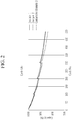
- FIG. 2 is a graph showing capacity retention during 45 °C/500 cycles.
- the rechargeable lithium battery cells manufactured according to Examples 1 and 2 were more improved in terms of high-temperature (45 °C) cycle capacity retention (%), compared with the rechargeable lithium battery cell manufactured according to Comparative Example 3.
- the separators manufactured according to examples includes a coating layer including the polyether-based polyurethane, thereby realizing a separator having improved thermal stability and moisture resistance, and implementing a rechargeable battery having improved cycle-life characteristics.
Landscapes
- Chemical & Material Sciences (AREA)
- Chemical Kinetics & Catalysis (AREA)
- General Chemical & Material Sciences (AREA)
- Electrochemistry (AREA)
- Engineering & Computer Science (AREA)
- Inorganic Chemistry (AREA)
- Materials Engineering (AREA)
- Manufacturing & Machinery (AREA)
- Composite Materials (AREA)
- Wood Science & Technology (AREA)
- Organic Chemistry (AREA)
- Life Sciences & Earth Sciences (AREA)
- Cell Separators (AREA)
- Secondary Cells (AREA)
Abstract
Description
- A separator for a rechargeable lithium battery and a rechargeable lithium battery including the same are disclosed.
- A separator for an electrochemical battery is an intermediate film that separates a positive electrode and a negative electrode in a battery, and maintains ion conductivity continuously to enable charge and discharge of a battery. When a battery is exposed to a high temperature environment due to abnormal behavior, a separator may be mechanically shrinks or is damaged due to melting characteristics at a low temperature. Herein, the positive and negative electrodes contact each other and may cause an explosion of the battery. In order to overcome this problem, technology of suppressing shrinkage of a separator and ensuring safety of a battery is required.
- In this regard, a method of increasing a thermal resistance of the separator by mixing a heat-resistance binder with the inorganic particles and coating a separator is known. As the heat-resistance binder, an SBR (styrene-butadiene rubber) binder or an aqueous binder is generally used.
- In the case of the SBR binder, mechanical properties of the SBR binder tend to be relatively low, leading to deterioration of long-term cycle-life characteristics of the battery.
- As the aqueous binder, an acrylic binder may be applied in a form of a salt dissolved in water so as to improve a binding strength with the inorganic particles, and thus a moisture content of the separator may be increased due to moisture absorption of the salt, which tends to reduce long-term cycle-life characteristics of the battery.
- Therefore, in order to provide a rechargeable lithium battery having excellent cycle-life characteristics, it is necessary to develop a separator capable of lowering a moisture content in the separator while having high heat resistance.
- A separator having a low content of residual moisture and a low shrinkage ratio at a high temperature, and a rechargeable lithium battery having excellent cycle-life characteristics and heat resistance characteristics are provided.
- In an embodiment, a separator for a rechargeable lithium battery includes a porous substrate and a coating layer disposed on at least one surface of the porous substrate, wherein the coating layer includes a binder including polyurethane and polyvinyl alcohol and inorganic particles and the polyurethane and the polyvinyl alcohol are included in a weight ratio of about 5 : 5 to about 9 : 1.
- Another embodiment provides a rechargeable lithium battery including a positive electrode, a negative electrode, and the separator for a rechargeable lithium battery disposed between the positive electrode and the negative electrode.
- The present invention provides a rechargeable lithium battery having a low content of residual moisture and a low shrinkage ratio at a high temperature, thereby ensuring both cycle-life characteristics and a heat resistance.
-
-
FIG. 1 is an exploded perspective view of a rechargeable lithium battery according to an embodiment. -
FIG. 2 is a graph showing capacity retention during 45 °C/500 cycles of the rechargeable lithium battery cells according to Examples 1 and 2 and Comparative Example 3. - Hereinafter, embodiments of the present invention are described in detail. However, these embodiments are exemplary, the present invention is not limited thereto and the present invention is defined by the scope of claims.
- As used herein, when a definition is not otherwise provided, "combination thereof" refers to a mixture, a copolymer, a blend, an alloy, a composite, a reaction product of components.
- As used herein, "(meth) acryl" may mean both acrylic and methacryl.
- In order to clearly describe the present disclosure, parts which are not related to the description are omitted, and the same reference numeral refers to the same or like components, throughout the specification. In addition, since the size and the thickness of each component shown in the drawing are optionally represented for convenience of the description, the present disclosure is not limited to the illustration.
- In the drawings, the thickness of layers, films, panels, regions, etc., are exaggerated for clarity. In the drawings, the thickness of a part of layers or regions, etc., is exaggerated for clarity. It will be understood that when an element such as a layer, film, region, or substrate is referred to as being "on" another element, it can be directly on the other element or intervening elements may also be present.
- A separator for a rechargeable lithium battery according to an embodiment includes a porous substrate and a coating layer, wherein the coating layer includes a binder including polyurethane and polyvinyl alcohol and inorganic particles and the polyurethane and the polyvinyl alcohol are included in a weight ratio of about 5 : 5 to about 9 : 1.
- The porous substrate may have a plurality of pores and may generally be a porous substrate used in an electrochemical device. Non-limiting examples of the porous substrate may be a glass fiber or a polymer film formed of a polymer, or a copolymer or a mixture of two or more selected from polyolefin such as polyethylene, polypropylene, and the like, a polyester such as polyethyleneterephthalate, polybutyleneterephthalate, and the like, polyacetal, polyamide, polyimide, polycarbonate, polyetheretherketone, polyaryletherketone, polyetherimide, polyamideimide, polybenzimidazole, polyethersulfone, polyphenylene oxide, a cyclic olefin copolymer, polyphenylene sulfide, polyethylenenaphthalate, Teflon, and polytetrafluoroethylene.
- The porous substrate may be for example a polyolefin-based substrate, and the polyolefin-based substrate may improve has safety of a battery due to its improved shutdown function. The polyolefin-based substrate may be for example selected from a polyethylene single film, a polypropylene single film, a polyethylene/polypropylene double film, a polypropylene/polyethylene/polypropylene triple film, and a polyethylene/polypropylene/polyethylene triple film. In addition, the polyolefin-based resin may include a non-olefin resin in addition to an olefin resin or a copolymer of olefin and a non-olefin monomer.
- The porous substrate may have a thickness of about 1 µm to about 40 µm, for example about 1 µm to about 30 µm, about 1 µm to about 20 µm, about 5 µm to about 20 µm, about 5 µm to about 15 µm, or about 10 µm to about 15 µm.
- The coating layer may be disposed on at least one surface of the porous substrate and may include a binder including polyurethane and polyvinyl alcohol and inorganic particles. For example, the coating layer composition may be coated on one surface of the porous substrate by a gravure coating method to provide the coating layer.
- The polyurethane and the polyvinyl alcohol may be applied in the form of a mixed composition.
- The polyurethane is a polymer having a plurality of urethane bonds, and the urethane bonds refers to a [-NHC(O)O-] structure formed by reacting an active hydroxyl group (-OH) of an alcohol and an isocyanate group (-N=C=O) of an isocyanate as in
Formula 1.
- The alcohol as a reactant for forming the polyurethanes may include, for example, polyether polyol, or polyester polyol.
- The polyurethane according to an embodiment of the present invention may be a polyether-based polyurethane formed from a polyether polyol and the polyether polyol may be an alcohol compound or a polymer having a polyvalent active hydroxyl group.
- For example, the polyether polyol may be prepared by reacting alkylene oxide with an initiator such as glycerol, and more specifically, may be prepared by reacting propylene oxide with an initiator such as glycerol, or copolymerizing ethylene oxide therewith to prepare a copolymer.
- The terminal end -OH group of the polyether polyol reacts with a polyvalent isocyanate group to provide polyether polyurethane.
- The isocyanate as a reactant which forms the polyurethane may be conventionally used isocyanate for preparing polyurethane.
- For example, the isocyanate includes, for example, aromatic diisocyanate having 6 to 20 carbon atoms (excluding carbon in NCO group, same as below), aliphatic diisocyanate having 2 to 18 carbon atoms, alicyclic diisocyanate having 4 to 15 carbon atoms, araliphatic diisocyanate having 8 to 15 carbon atoms, (such as carbodiimide-modified diisocyanate, urethane-modified diisocyanate, uretdione-modified diisocyatate, etc.) modified ones of these diisocyanates, and mixtures of two or more types thereof.
- As used herein, "araliphatic" may mean aliphatic compound containing one or more aryl groups.
- Specific examples of the aromatic diisocyanate include 1,3- or 1,4-phenylene diisocyanate, 2,4- or 2,6-tolylene diisocyanate, 2,4'- or 4,4'-diphenylmethanedi isocyanate (hereinafter "MDI"), 4,4'-diisocyanatobiphenyl, 3,3'-dimethyl-4,4'-diisocyanatobiphenyl, 3,3'-dimethyl-4,4'- diisocyanatodiphenylmethane, 1,5-naphthylene diisocyanate, and the like.
- Specific examples of the aliphatic diisocyanate include ethylene diisocyanate, tetramethylene diisocyanate, hexamethylene diisocyanate, dodecamethylene diisocyanate, 2,2,4-trimethylhexamethylene diisocyanate, lysine diisocyanate, 2,6-diisocyanatomethylcaproate, bis(2-isocyanatoethyl) carbonate, 2-isocyanatoethyl-2,6-diisocyanatohexanoate, and the like.
- Specific examples of the alicyclic diisocyanate include isophorone diisocyanate, dicyclohexyl methane-4,4'-diisocyanate, cyclohexylene diisocyanate, methylcyclohexylene diisocyanate, bis(2-isocyanatoethyl)-4-cyclohexylene-1,2-dicarboxylate, 2,5- or 2,6-norbornane diisocyanate, and the like.
- Specific examples of the araliphatic diisocyanate include m- or p-xylylene diisocyanate, α, α, α', α'-tetramethylxylylene diisocyanate, and the like.
- It may be desirably an aromatic diisocyanate and an alicyclic diisocyanate, more desirably an aromatic diisocyanate, and even more desirably MDI.
- A weight average molecular weight of the polyether-based polyurethane may be about 1,000 to about 150,000, for example about 10,000 to about 150,000, or about 100,000 to about 150,000.
- By including the polyether-based polyurethane, a water repellent function may be improved, and thus water adsorption of the separator may be lowered, and consequently a water content of the separator may be lowered, improving long-term cycle-life characteristics of the battery.
- The polyvinyl alcohol according to an embodiment of the present invention may be used without limitation as long as it is known in the art.
- A saponification degree (measured based on JIS K 6726 (1994 version)) of the polyvinyl alcohol may be greater than or equal to about 80 mol%, for example, about 80 mol% to about 100 mol%, or about 90 mol% to about 100 mol%, or about 95 mol% to about 100 mol%. If the saponification degree is too low, the number of hydroxyl groups may be decreased and adhesion may be decreased, so that adhesion performance between the current collector and the active material may be decreased.
- In addition, an average polymerization degree (measured based on JIS K 6726 (1994 version)) of the polyvinyl alcohol may be greater than or equal to about 300, for example, about 300 to about 3,500, about 500 to about 3,500, or about 1,500 to about 3,500. If the average polymerization degree is too low, mechanical strength, adhesion, etc. may be deteriorated, while if the average polymerization degree is too high, an elastic force may be decreased, and solubility in the solvent during the electrode manufacturing process may be decreased so that it tends to be difficult to handle.
- In the polyether-based polyurethane included in the coating layer composition according to an embodiment, there is no functional group capable of reacting with the hydroxyl group (-OH) of polyvinyl alcohol, the polyurethane and polyvinyl alcohol have no cross-linking reactivity. As such, they may be present in the composition in a simply mixed form rather than in a cross-linked polymer.
- The polyurethane and the polyvinyl alcohol may be included in a weight ratio of about 5: 5 to about 9: 1, respectively.
- For example, the polyurethane and the polyvinyl alcohol may be included in a weight ratio of about 5: 5 to about 8: 2 or a weight ratio of about 6: 4 to about 8: 2, respectively.
- When the contents of the polyurethane and polyvinyl alcohol are within the above range, water-reducing effects and ion conductivity required in the separator may simultaneously be achieved.
- The binder may further include a heat-resistance binder.
- The heat-resistance binder may connect the inorganic particles included in the coating layer in a point contact or a surface contact manner to prevent the inorganic particles from being detached.
- For example, the heat-resistance binder may be a (meth)acryl-based resin.
- The (meth)acryl-based resin may include an acrylic copolymer including a repeating unit derived from an alkyl (meth)acrylate monomer as an example of a polymer of a (meth)acrylic monomer. Examples of the alkyl (meth)acrylate monomers may include n-butyl (meth)acrylate, ethyl (meth)acrylate, propyl (meth)acrylate, t-butyl (meth)acrylate and isobutyl (meth)acrylate, pentyl (meth)acrylate, hexyl (meth)acrylate, heptyl (meth)acrylate, isooctyl (meth)acrylate, octyl (meth)acrylate, nonyl (meth)acrylate, decyl (meth)acrylate, undecyl (meth)acrylate, lauryl (meth)acrylate, methyl (meth)acrylate, isobornyl (meth)acrylate, cyclohexyl (meth)acrylate, but are not limited thereto. For example, straight or branched alkyl (meth)acrylate having 1 to 20 carbon atoms may be used.
- The (meth)acryl-based resin may be included in an amount of about 10 wt% to about 80 wt%, for example, about 20 wt% to about 70 wt% or about 30 wt% to about 50 wt%, based on a total amount of the binder.
- The polyurethane may be included in an amount of about 10 wt% to about 80 wt%, for example about 20 wt% to about 80 wt% or about 30 wt% to about 80 wt%, based on a total amount of the binder.
- The polyvinyl alcohol may be included in an amount of about 5 wt% to about 30 wt%, for example about 10 wt% to about 30 wt% or about 10 wt% to about 25 wt%, based on a total amount of the binder.
- Since the (meth)acryl-based resin is included in the above range, not only the adhesive force of the separator may be improved but also heat resistance may be ensured.
- In addition, by including the polyurethane in the above range, a water-reducing effect may be obtained, and by including the polyvinyl alcohol in the above range, the adhesive effect of the inorganic particles and the film may be obtained.
- As another example, the heat-resistance binder may be a cross-linked polymer obtained by a reaction of the polyurethane and a cross-linking agent.
- For example, the cross-linking agent may be a monomer, an oligomer, and/or a polymer including a functional group having reactivity with inorganic particles and/or a polar functional group of the polyurethane.
- The functional group of the cross-linking agent may form a covalent bond with the polar functional group present in the inorganic particles and/or the polyurethane, and thus may serve to be more firmly bound to the inorganic particles and the polyurethane.
- That is, in the binder, the polyurethane and the inorganic particles may be organically connected through a cross-linking agent, and as a result, the coating layer may be improved in heat resistance without separately including a heat-resistance binder such as a (meth)acryl-based resin. In addition, a surface area of the polyurethane exposed on the surface of the coating layer may be increased, thereby improving adhesion to the electrode plate.
- The cross-linking agent may be present in the form of a cross-linked polymer which is a resulting material of a reaction with the inorganic particles and/or the polyurethane in a binder.
- The cross-linking agent may include a functional group having reactivity with a polar functional group. For example, the cross-linking agent may include a functional group having reactivity with a carboxyl group, a functional group having reactivity with a hydroxy group, a functional group having reactivity an amine group, a functional group having reactivity water, or a combination thereof.
- For example, the cross-linking agent may be a monomer, an oligomer, and/or a polymer including a functional group having reactivity a carboxyl group of the polyurethane.
- Specifically, the cross-linking agent may be a carbodiimide-based compound, a melamine compound, an aziridine compound, an isocyanate compound, or a combination thereof. Specific examples of the carbodiimide-based compound may include N,N'-di-o-tolylcarbodiimide, N,N'-diphenylcarbodiimide, N,N'-dioctyldecylcarbodiimide, N,N'-di-2,6-diketylphenylcarbodiimide, N-tolyl-N'cyclohexylcarbodiimide, N,N'-di-2,6-diisopropylphenylcarbodiimide, N,N'-di -2,6-di-tert-butylphenylcarbodiimide, N-tolyl-N'-phenylcarbodiimide, N,N'-di-p-nitrophenylcarbodiimide, N,N'-di-p-aminophenylcarbodiimide, N,N'-di-p-hydroxyphenylcarbodiimide, N,N'-di-cyclohexylcarbodiimide, N,N'-di-p-tolylcarbodiimide, p-phenylene-bis-di-o-tolyl carbodiimide, p-phenylene-bisdicyclohexylcarbodiimide, hexamethylene-bisdicyclohexylcarbodiimide, ethylene-bisdiphenylcarbodiimide, benzene-2,4-diisocyanato-1,3,5-tris(1-methylethyl) homopolymer, a copolymer of 2,4-diisocyanato-1,3,5-tris(1-methylethyl) and 2,6-diisopropyl diisocyanate, or a combination thereof, but are not necessarily limited thereto, and may be any carbodiimide compound in the art.
- In the binder, the carbodiimide-based compound may exist in a form of a cross-linked polymer which is a resulting material of a reaction with the inorganic particles and/or polyurethane. For example, the diimide bond of the carbodiimide-based compound may react with the carboxyl group of the polyurethane to provide a cross-linked polymer in which a new covalent bond is formed.
- For example, the cross-linking agent may be a silane coupling agent. The silane coupling agent is an organosilicon compound having a hydrolyzable functional group. The hydrolyzable functional group is a functional group capable of bonding with inorganic particles such as silica after hydrolysis. For example, the silane coupling agent may include one or more selected from an alkoxy group, a halogen group, an amino group, a vinyl group, a glycidoxy group, and a hydroxy group.
- Specifically, the silane coupling agent may be at least one selected from vinylalkylalkoxysilane, epoxyalkylalkoxysilane, mercaptoalkylalkoxysilane, vinylhalosilane, and alkylacyloxysilane.
- Specific examples of the silane coupling agent may include vinylalkylalkoxysilanes such as vinyltris(β-methoxyethoxy) silane and γ-methacrylooxypropyltrimethoxysilane; epoxy alkylalkoxysilanes such as γ-glycidoxypropyltrimethoxysilane, β-(3,4-epoxycyclohexyl) ethyltrimethoxysilane, and γ-glycidoxypropylmethyldiethoxysilane; aminoalkylalkoxysilanes such as γ-aminopropyltriethoxysilane; mercaptoalkylalkoxysilanes such as γ-mercaptopropyltrimethoxysilane; halogenated alkylalkoxysilanes such as γ-chloropropyltrimethoxysilane; vinyl halosilanes such as vinyl trichlorosilane; alkylacyloxysilanes such as methyltriacetoxysilane; and the like, but are not necessarily limited thereto, and may be any silane coupling agent that may be used in the art.
- In addition to the cross-linking agent, a hydrazine compound, a urea compound, an epoxy compound, an oxazoline compound, and the like may be used. However, the present invention is not limited thereto, and any one that may be used as a cross-linking agent in the art may be used. These compounds may be used alone or in a mixture.
- Specifically, APA series (APA-M950, APA-M980, APA-P250, APA-P280, etc.) of Otsuka Chemical Co., Ltd. may be used as the hydrazine compound.
- BASONAT PLR8878 from BASF, BASONAT HW-100, Bayhydur 3100 from Sumitomo Bayurethane Co., Ltd., Bayheur VPLS2150/1, and the like may be used as the isocyanate compound.
- As the melamine compound, Cymel 325 etc. of Mitsui Cytec Company may be used.
- As the urea compound, becamine series etc. made by DIC Corporation may be used.
- As the epoxy compound, the denacor series (EM-150, EM-101, etc.) by Nagase Chemtech Co., Ltd., and Adegin EM-00517, EM-0526, EM-051R, EM-11-50B by ADEKA Corporation, and the like may be used.
- As the carbodiimide compound, carbojilite series of Nisshinbo Chemical Co., Ltd. (SV-02, V-02, V-02-L2, V-04, E-01, E-02, V-01, V-03, V- 07, V-09, V-05, and the like may be used.
- As the oxazoline compound, Nippon Shokubai's epochross series (WS-500, WS-700, K-1010E, K-1020E, K-1030E, K-2010E, K-2020E, K-2030E), and the like may be used..
- These are commercially available as a dispersion body or solution including a cross-linking agent.
- The cross-linking agent may be included in an amount of 0.03 parts by weight to about 10 parts by weight based on 100 parts by weight of the binder. For example, it may be included in an amount of about 0.03 parts by weight to about 7 parts by weight, about 0.1 parts by weight to about 7 parts by weight, or about 1 part by weight to about 7 parts by weight.
- When the content of the cross-linking agent satisfies the above range, the cross-linking agent may sufficiently be bound to the polyurethane and the inorganic particles, and thus a rechargeable lithium battery including the same may secure sufficient heat resistance. In addition, when the content of the cross-linking agent satisfies the above range, a large amount of unreacted cross-linking agent does not remain, thereby preventing deterioration of characteristics of a rechargeable lithium battery including the same.
- The cross-linked polymer may further improve heat resistance as the cross-linking degree becomes higher.
- The cross-linked polymer may have a weight average molecular weight of about 500 g/mol to about 80,000 g/mol, for example, about 2,000 g/mol to about 60,000 g/mol. Heat resistance may be ensured by including the cross-linked binder which has the weight average molecular weight within the range.
- In addition, due to the cross-linked structure, impregnation of an electrolyte may be improved, and when the separator is used in a battery, the charge and discharge characteristics of the battery may be improved. In addition, binder components are not easily dissolved in the electrolyte by physical and chemical bonds between the molecules constituting the binder.
- Meanwhile, the composition for forming the coating layer may include a dispersant and a solvent in addition to the polyurethane and the cross-linking agent.
- The dispersant may be included in an amount of about 0.1 parts by weight to 10 parts by weight based on 100 parts by weight of the inorganic particles. For example, it may be included in an amount of about 0.1 parts by weight to about 5 parts by weight.
- The solvent is not particularly limited as long as it is capable of dissolving or dispersing the aforementioned polyurethane, polyvinyl alcohol, (meth) acrylic resin, cross-linking agent and dispersant, and may include, for example, one of or at least two of water (pure water, ultrapure water, distilled water, ion exchanged water, etc.); alcohols such as methanol, ethanol and isopropyl alcohol; dimethylformamide, dimethylacetamide, tetramethylurea, triethylphosphate, N-methyl-2-pyrrolidone, dimethyl sulfoxide, acetone, methyl ethyl ketone, methyl isobutyl ketone, and cyclohexanone. For example, the aqueous solvent may be used, but is not limited thereto.
- The curing may be performed by a method of photo-curing, thermal curing, or a combination thereof. The photo-curing may be performed, for example, by irradiating UV at about 150 nm to about 170 nm for about 5 seconds to about 60 seconds.
- The thermal curing may be performed, for example, at a temperature of about 60 °C to about 120 °C for about 1 hour to about 36 hours, for example, at a temperature of about 80 °C to about 100 °C for about 10 hours to about 24 hours.
- The inorganic particles may prevent the separator from being rapidly contracted or deformed due to temperature increase. The inorganic particles may be a ceramic material capable of improving heat resistance, for example, Al2O3, SiO2, TiO2, SnO2, CeO2, MgO, NiO, CaO, GaO, ZnO, ZrO2, Y2O3, SrTiO3, BaTiO3, Mg(OH)2, boehmite, or a combination thereof, but is not limited thereto. The inorganic particles may be spherical, plate-shaped, cubic, or amorphous. An average particle diameter of the inorganic particles may be about 0.3 µm to about 0.9 µm, for example about 0.4 µm to about 0.9 µm, or about 0.5 µm to about 0.9 µm.
- The average particle diameter of the inorganic particles may be a particle size (D50) at 50% by volume in a cumulative size-distribution curve. By using inorganic particles having the average particle diameter within the above range, it is possible to impart proper strength to the coating layer, thereby improving heat resistance, durability, and stability of the separator.
- The binder may be included in an amount of about 1 wt% to about 10 wt%, for example about 2 wt% to about 8 wt%, based on a total amount of the coating layer.
- The inorganic particles may be included in an amount of about 90 wt% to about 99 wt% based on a total amount of the coating layer. For example, the inorganic particles may be included in an amount of about 92 wt% to about 98 wt%, for example about 93 wt% to about 98 wt%, about 94 wt% to about 98 wt%, or about 95 wt% to about 98 wt% based on a total amount of the coating layer.
- When the coating layer includes the binder and inorganic particles within the above ranges, the separator for a rechargeable lithium battery may exhibit improved heat resistance, durability, oxidation resistance, and stability.
- A thickness of the coating layer may be about 3.0 µm to about 7 µm. For example, it may be about 3.0 µm to about 6 µm, or about 3.0 µm to about 5 µm.
- A ratio of the thickness of the coating layer relative to the thickness of the porous substrate may be about 0.05 to about 0.5, for example, about 0.05 to about 0.4, or about 0.05 to about 0.3. In this case, the separator including the porous substrate and the coating layer may exhibit improved air permeability, heat resistance, and adhesion.
- The separator for the rechargeable lithium battery according to an embodiment may be manufactured by various known methods. For example, the separator for the rechargeable lithium battery may be formed by coating a composition for forming a coating layer on one or both surfaces of the porous substrate and then drying it.
- The coating may be, for example a spin coating, a dip coating, a bar coating, a die coating, a slit coating, a roll coating, an inkjet printing, and the like, but is not limited thereto.
- The drying may be for example performed through natural drying, drying with warm air, hot air, or low humid air, vacuum-drying, or radiation of a far-infrared ray, an electron beam, and the like, but the present disclosure is not limited thereto. The drying may be for example performed at a temperature of about 25 °C to about 120 °C.
- The separator for the rechargeable lithium battery may be manufactured by lamination, coextrusion, and the like in addition to the above method.
- Hereinafter, a rechargeable lithium battery including the separator for the rechargeable lithium battery is described.
- A rechargeable lithium battery may be classified into a lithium ion battery, a lithium ion polymer battery, and a lithium polymer battery depending on kinds of a separator and an electrolyte. It also may be classified to be cylindrical, prismatic, coin-type, pouch-type, and the like depending on a shape. In addition, it may be bulk type and thin film type depending on sizes. Structures and manufacturing methods for these batteries pertaining to this disclosure are well known in the art.
- Herein, as an example of a rechargeable lithium battery, a cylindrical rechargeable lithium battery is for example described.
FIG. 1 is an exploded perspective view showing a rechargeable lithium battery according to an embodiment. Referring toFIG. 1 , arechargeable lithium battery 100 according to an embodiment includes a battery cell including anegative electrode 112, apositive electrode 114 facing thenegative electrode 112, aseparator 113 disposed between thenegative electrode 112 and thepositive electrode 114, and an electrolyte solution (not shown) immersed in thenegative electrode 112,positive electrode 114 andseparator 113, abattery case 120 housing the battery cell, and a sealingmember 140 sealing thebattery case 120. - The
positive electrode 114 includes a positive current collector and a positive active material layer formed on the positive current collector. The positive active material layer includes a positive active material, a positive electrode binder, and optionally a conductive material. - The positive current collector may use aluminum, nickel, and the like, but is not limited thereto.
- The positive active material may use a compound capable of intercalating and deintercalating lithium. Specifically, at least one of a composite oxide or a composite phosphate of a metal selected from cobalt, manganese, nickel, aluminum, iron, or a combination thereof and lithium may be used. For example, the positive active material may be a lithium cobalt oxide, a lithium nickel oxide, a lithium manganese oxide, a lithium nickel cobalt manganese oxide, a lithium nickel cobalt aluminum oxide, a lithium iron phosphate, or a combination thereof.
- The positive electrode binder improves binding properties of positive active material particles with one another and with a current collector, and specific examples may be polyvinyl alcohol, carboxylmethyl cellulose, hydroxypropyl cellulose, diacetyl cellulose, polyvinylchloride, carboxylated polyvinylchloride, polyvinylfluoride, an ethylene oxide-containing polymer, polyvinylpyrrolidone, polyurethane, polytetrafluoroethylene, polyvinylidene fluoride, polyethylene, polypropylene, a styrene-butadiene rubber, an acrylated styrene-butadiene rubber, an epoxy resin, nylon, and the like, but are not limited thereto. These may be used alone or as a mixture of two or more.
- The conductive material improves conductivity of an electrode and examples thereof may be natural graphite, artificial graphite, carbon black, a carbon fiber, a metal powder, a metal fiber, and the like, but are not limited thereto. These may be used alone or as a mixture of two or more. The metal powder and the metal fiber may use a metal of copper, nickel, aluminum, silver, and the like.
- The
negative electrode 112 includes a negative current collector and a negative active material layer formed on the negative current collector. - The negative current collector may use copper, gold, nickel, a copper alloy, and the like, but is not limited thereto.
- The negative active material layer may include a negative active material, a negative electrode binder, and optionally a conductive material. The negative active material may be a material that reversibly intercalates/deintercalates lithium ions, a lithium metal, a lithium metal alloy, a material capable of doping and dedoping lithium, a transition metal oxide, or a combination thereof.
- The material that reversibly intercalates/deintercalates lithium ions may be a carbon material which is any generally-used carbon-based negative active material, and examples thereof may be crystalline carbon, amorphous carbon, or a combination thereof. Examples of the crystalline carbon may be graphite such as amorphous, sheet-shape, flake, spherical shape or fiber-shaped natural graphite or artificial graphite. Examples of the amorphous carbon may be soft carbon or hard carbon, a mesophase pitch carbonized product, fired coke, and the like. The lithium metal alloy may be an alloy of lithium and a metal selected from Na, K, Rb, Cs, Fr, Be, Mg, Ca, Sr, Si, Sb, Pb, In, Zn, Ba, Ra, Ge, Al, and Sn. The material capable of doping and dedoping lithium may be Si, SiOx (0<x<2), a Si-C composite, a Si-Y alloy, Sn, SnO2, a Sn-C composite, a Sn-Y alloy, and the like, and at least one of these may be mixed with SiO2. Specific examples of the element Y may be selected from Mg, Ca, Sr, Ba, Ra, Sc, Y, Ti, Zr, Hf, Rf, V, Nb, Ta, Db, Cr, Mo, W, Sg, Tc, Re, Bh, Fe, Pb, Ru, Os, Hs, Rh, Ir, Pd, Pt, Cu, Ag, Au, Zn, Cd, B, Al, Ga, Sn, In, TI, Ge, P, As, Sb, Bi, S, Se, Te, Po, and a combination thereof. The transition metal oxide may be vanadium oxide, lithium vanadium oxide, and the like.
- The negative electrode binder and the conductive material used in the
negative electrode 112 may be the same as the positive electrode binder and the conductive material of the aforementionedpositive electrode 114. - The
positive electrode 114 and thenegative electrode 112 may be manufactured by mixing each active material composition including each active material and a binder, and optionally a conductive material in a solvent, and coating the active material composition on each current collector. Herein, the solvent may be N-methylpyrrolidone, and the like, but is not limited thereto. The electrode manufacturing method is well known, and thus is not described in detail in the present specification. - The electrolyte solution includes an organic solvent a lithium salt.
- The organic solvent serves as a medium for transmitting ions taking part in the electrochemical reaction of a battery. The organic solvent may be a carbonate-based solvent, an ester-based solvent, an ether-based solvent, a ketone-based solvent, an alcohol-based solvent, and an aprotic solvent. The carbonate-based solvent may be dimethyl carbonate, diethyl carbonate, dipropyl carbonate, methylpropyl carbonate, ethylpropyl carbonate, methylethyl carbonate, ethylene carbonate, propylene carbonate, butylene carbonate, and the like, and the ester-based solvent may be methyl acetate, ethyl acetate, n-propyl acetate, 1,1-dimethylethyl acetate, methylpropionate, ethylpropionate, γ-butyrolactone, decanolide, valerolactone, mevalonolactone, caprolactone, and the like. The ether-based solvent may be dibutyl ether, tetraglyme, diglyme, dimethoxyethane, 2-methyltetrahydrofuran, tetrahydrofuran, and the like, and the ketone-based solvent may be cyclohexanone, and the like. The alcohol-based solvent may be ethanol, isopropyl alcohol, and the like, and the aprotic solvent may be nitriles such as R-CN (R is a C2 to C20 linear, branched, or cyclic hydrocarbon group, a double bond, an aromatic ring, or an ether bond), and the like, amides such as dimethyl formamide, dioxolanes such as 1,3-dioxolane, sulfolanes, and the like.
- The organic solvent may be used alone or in a mixture of two or more, and when the organic solvent is used in a mixture of two or more, the mixture ratio may be controlled in accordance with a desirable cell performance.
- The lithium salt is dissolved in an organic solvent, supplies lithium ions in a battery, basically operates the rechargeable lithium battery, and improves lithium ion transportation between positive and negative electrodes therein. Examples of the lithium salt may include LiPF6, LiBF4, LiSbF6, LiAsF6, LiN(SO3C2F5)2, LiN(CF3SO2)2, LiC4F9SO3, LiClO4, LiAlO2, LiAlCl4, LiN(CxF2x+1SO2)(CyF2y+1SO2) (x and y are natural numbers), LiCl, LiI, LiB(C2O4)2, or a combination thereof, but are not limited thereto.
- The lithium salt may be used in a concentration ranging from about 0.1 M to about 2.0 M. When the lithium salt is included within the above concentration range, an electrolyte may have excellent performance and lithium ion mobility due to optimal electrolyte conductivity and viscosity.
- Hereinafter, the above aspects of the present disclosure are illustrated in more detail with reference to examples. However, these examples are exemplary, and the present disclosure is not limited thereto.
- 3.81 parts by weight of polyether-based polyurethane (Sancure 2710, Lubrizol), 0.23 parts by weight of a cross-linking agent (Picassian® XL-732, STAHL), 0.95 parts by weight of polyvinyl alcohol (PVA-500, Daejung Chemicals and Metals Co., Ltd.), 95.24 parts by weight of boehmite (Nabaltec AOH60), and 150 parts by weight of DI water were mixed and dispersed with a mechanical stirring equipment at 25°C for 30 minutes to prepare coating layer composition having a solid content of 40 wt%.
- The composition was bar-coated to be 3 µm thick on a 12 µm-thick polyethylene porous substrate (Air permeability: 120 sec/100cc, Puncture strength: 450 kgf, SK Co., Ltd.) and then, dried at 70°C for 10 minutes to manufacture a separator for rechargeable lithium battery cell.
- 1.9 parts by weight of polyether-based polyurethane (Sancure 2710, Lubrizol), 0.95 parts by weight of polyvinyl alcohol (PVA-500, Daejung Chemicals and Metals Co., Ltd.), 1.9 parts by weight of a (meth)acryl-based resin (Carbosperse-k-702, Lubrizol), 95.24 parts by weight of boehmite (Nabaltec AOH60), and 150 parts by weight of DI (deionized) water were mixed and dispersed with a mechanical stirring equipment at 25°C for 30 minutes to prepare a coating layer composition having a solid content of 40 wt%, and then, the coating layer composition was used to manufacture a separator for a rechargeable battery according to the same method as Example 1.
- 3.8 parts by weight of polyether-based polyurethane (Sancure 2710, Lubrizol), 0.95 parts by weight of polyvinyl alcohol (PVA-500, Daejung Chemicals and Metals Co., Ltd.), 95.24 parts by weight of boehmite (Nabaltec AOH60), and 150 parts by weight of DI (deionized) water were mixed and dispersed with a mechanical stirring equipment at 25°C for 30 minutes to prepare a coating layer composition having a solid content of 40 wt%, and then, the coating layer composition was used to manufacture a separator for a rechargeable battery according to the same method as Example 1.
- A separator for a rechargeable battery was manufactured according to the same method as Example 1 except that 1.9 parts by weight of a polyester-based polyurethane (Sancure 835, Lubrizol), 1.9 parts by weight of a (meth)acryl-based resin (Carbosperse-k-702, Lubrizol), 0.95 parts by weight of polyvinyl alcohol (PVA-500, Daejung Chemicals and Metals Co., Ltd.), 95.24 parts by weight of boehmite (Nabaltec AOH60), and 150 parts by weight of DI (deionized) water were used instead of the polyether-based polyurethane.
- 3.8 parts by weight of a (meth)acryl-based resin (Carbosperse-k-702, Lubrizol), 0.95 parts by weight of polyvinyl alcohol (PVA-500, Daejung Chemicals and Metals Co., Ltd.), 95.24 parts by weight of boehmite (Nabaltec AOH60), and 150 parts by weight of DI (deionized) water were mixed and dispersed with a mechanical stirring equipment at 25°C for 30 minutes to prepare a coating layer composition having a solid content of 40 wt%, and then, the coating layer composition was used to manufacture a separator for a rechargeable battery according to the same method as Example 1.
- A method of measuring moisture contents of the separators is not particularly limited, and non-limiting examples thereof are as follows: the separators respectively having a coating layer (after removing a package when packed) were stored in an 80°C chamber for 24 hours, and stored in an 17°C to 20 °C, at a dew point of -80°C to -90°C for 24 hours, and then, 2.0 g to 3.0 g of each separator was loaded in a capping vial. The vial was put in 860 Thermoprep (Metrohm AG) and heated at 150°C, and moisture contents (X ppm) of the separators were measured through automatic moisture measurement in a Karl-Fisher method for 10 minutes with 831 KF coulometer (Metrohm AG).
- The results are shown in Table 1.
- A method of measuring thermal shrinkage rates of the separators is not particularly limited thereto but may be a common method used in a technology field of the present invention. Non-limiting examples of the method of the thermal shrinkage rates of the separators are as follows: the separators were respectively cut into a width (MD) of about 10 cm x a length (TD) of about 10 cm, stored in a 200°C chamber for 10 minutes, and then, measured with respect to a shrinkage rate in a MD direction and in a TD direction to respectively calculate an MD direction thermal shrinkage rate and a TD direction thermal shrinkage rate according to
Formulae 

- The calculated values according to
Formulae (Table 1) Drying at 80°C for 24 hr (ppm) Thermal shrinkage rate (200°C, 1 hr (%)) Example 1 167 5%↓ Example 2 353 5%↓ Comparative Example 1 170 30%↑ Comparative Example 2 1200 5%↓ Comparative Example 3 1200 5%↓ - Referring to Table 1, the separators including polyurethane and a (meth)acryl-based resin or a cross-linked polymer obtained by a reaction of the polyurethane and a cross-linking agent exhibited improved water repellent. Particularly, when polyether-based polyurethane was used rather than polyester-based polyurethane (Comparative Example 2), moisture-reducing characteristics were much improved.
- In addition, the separators including the polyurethane and the (meth)acryl-based resin or the cross-linked polymer obtained by a reaction of the polyurethane and the cross-linking agent exhibited improved heat-resistance properties.
- LiCoO2 as a positive active material, polyvinylidene fluoride (PVDF) as a binder, and carbon as a conductive agent were mixed in a weight ratio of 92:4:4 and then, dispersed in N-methyl-2-pyrrolidone to prepare positive electrode slurry. This slurry was coated to be 20 µm thick on an aluminum foil and then, dried and compressed to manufacture a positive electrode.
- Artificial graphite as a negative electrode active material, a styrene-butadiene rubber as a binder, and carboxylmethyl cellulose as a thickener were mixed in a weight ratio of 96:2:2 and dispersed in water to prepare negative electrode active material slurry. This slurry was coated to be 15 µm thick on a copper foil and then, dried and compressed to manufacture a negative electrode.
- The manufactured positive and negative electrodes and the separators according to Examples 1 to 2 and Comparative Example 3 respectively were used to manufacture cylindrical battery cells. An electrolyte solution was prepared by using a mixed solution of ethyl carbonate (EC)/ethylmethyl carbonate (EMC)/diethyl carbonate (DEC) (a volume ratio of 3/5/2) including LiPF6 at a concentration of 1.3 M.
- The lithium rechargeable battery cells according to Examples 1 and 2 and Comparative Example 3 were charged and discharged at 45 °C in a range of 2.8 V to 4.2 V to conduct a standard charge and discharge experiment.
- Subsequently, the cells were constant current-charged in a high temperature (45 °C) chamber at a current of 1.0 C rate up to 4.25 V and then, constant voltage-charged until the current reached 0.05 C while 4.25 V was maintained. Then, the cells were discharged down to a voltage of 2.8 V at a constant current of 1.0 C. This standard charge and standard discharge was performed once every 100th charge and discharge. These charges and discharges were repeated up to 500 cycles to evaluate cycle-life characteristics. The cells were respectively measured with respect to discharge capacity at each cycle and discharge capacity at the 500th cycle, which were used to calculate cycle capacity retention (%) at a high temperature (45 °C) according to Formula 4. The results are shown in
FIG. 2 .
-
FIG. 2 is a graph showing capacity retention during 45 °C/500 cycles. - Referring to
FIG. 2 , the rechargeable lithium battery cells manufactured according to Examples 1 and 2 were more improved in terms of high-temperature (45 °C) cycle capacity retention (%), compared with the rechargeable lithium battery cell manufactured according to Comparative Example 3. - In summary, the separators manufactured according to examples includes a coating layer including the polyether-based polyurethane, thereby realizing a separator having improved thermal stability and moisture resistance, and implementing a rechargeable battery having improved cycle-life characteristics.
-
- 100: rechargeable lithium battery
- 112: negative electrode
- 113: separator
- 114: positive electrode
- 120: battery case
- 140: sealing member
Claims (15)
- A separator (113) for a rechargeable lithium battery (100) comprising
a porous substrate and a coating layer disposed on at least one surface of the porous substrate,
wherein the coating layer comprises a binder comprising polyurethane and polyvinyl alcohol and inorganic particles, and
the polyurethane and the polyvinyl alcohol are included in a weight ratio of about 5 : 5 to about 9 : 1. - The separator (113) of claim 1, wherein the binder further comprises a (meth)acryl-based resin.
- The separator (113) of claim 2, wherein the (meth)acryl-based resin is included in an amount of about 10 wt% to about 80 wt% based on a total amount of the binder.
- The separator (113) of one of the preceeding claims, wherein the polyurethane is included in an amount of about 10 wt% to about 80 wt% based on a total amount of the binder.
- The separator (113) of one of the preceeding claims, wherein the polyvinyl alcohol is included in an amount of about 5 wt% to about 30 wt% based on a total amount of the binder.
- The separator (113) of one of the preceeding claims , wherein the coating layer further comprises a cross-linking agent, the cross linking agent being bound to the polyurethane and/or the inorganic particles, wherein optionally the cross-linking agent is bound to the polyurethane to form a cross-linked polymer, and a weight average molecular weight of the cross-linked polymer is about 500 g/mol to about 80,000 g/mol.
- The separator (113) of claim 6, wherein the cross-linking agent is included in an amount of about 0.03 parts by weight to about 10 parts by weight based on 100 parts by weight of the binder.
- The separator (113) of claims 6 or 7, wherein the cross-linking agent comprises a carbodiimide-based compound, a melamine compound, an aziridine compound, an isocyanate compound, or a combination thereof.
- The separator (113) of claims 6 to 8, which further comprises a dispersant.
- The separator (113) of claim 9, wherein the dispersant is included in an amount of about 0.1 parts by weight to about 10 parts by weight based on 100 parts by weight of the inorganic particles.
- The separator (113) of one of the preceeding claims, wherein the polyurethane is polyether-based polyurethane.
- The separator of claim 11, wherein a weight average molecular weight of the polyether-based polyurethane is about 1,000 to about 150,000.
- The separator of one of the preceeding claims, wherein an average polymerization degree of the polyvinyl alcohol is greater than or equal to about 300 and a saponification degree of the polyvinyl alcohol is greater than or equal to about 80 mol%.
- The separator of one of the preceeding claims, wherein the inorganic particles are included in an amount of about 90 wt% to about 99 wt% based on a total amount of the coating layer.
- A rechargeable lithium battery (100) comprising
a positive electrode (114), a negative electrode (112), and the separator (113) for the rechargeable lithium battery (100) of any one of claim 1 to claim 14 disposed between the positive electrode (114) and the negative electrode (112).
Applications Claiming Priority (1)
| Application Number | Priority Date | Filing Date | Title |
|---|---|---|---|
| KR1020190025306A KR102376444B1 (en) | 2019-03-05 | 2019-03-05 | Separator for rechargeable lithium battery and rechargeable lithium battery including the same |
Publications (2)
| Publication Number | Publication Date |
|---|---|
| EP3706199A1 true EP3706199A1 (en) | 2020-09-09 |
| EP3706199B1 EP3706199B1 (en) | 2023-05-24 |
Family
ID=69770658
Family Applications (1)
| Application Number | Title | Priority Date | Filing Date |
|---|---|---|---|
| EP20160978.1A Active EP3706199B1 (en) | 2019-03-05 | 2020-03-04 | Separator for rechargeable lithium battery and rechargeable lithium battery including the same |
Country Status (4)
| Country | Link |
|---|---|
| US (1) | US11923496B2 (en) |
| EP (1) | EP3706199B1 (en) |
| KR (1) | KR102376444B1 (en) |
| CN (1) | CN111668429B (en) |
Families Citing this family (3)
| Publication number | Priority date | Publication date | Assignee | Title |
|---|---|---|---|---|
| KR102368234B1 (en) * | 2021-10-26 | 2022-03-03 | 주식회사 케이엠지 | Binder for secondary battery, composite separator and secondary battery prepared by using the same |
| KR20260027408A (en) * | 2024-08-20 | 2026-03-03 | 삼성에스디아이 주식회사 | Separator for rechargeable lithium battery and rechargeable lithium battery including the same |
| CN119833877B (en) * | 2025-01-09 | 2025-11-07 | 河北金力新能源科技股份有限公司 | High heat-resistant Gao Xiye liquid retention rate lithium battery diaphragm and preparation method thereof |
Citations (2)
| Publication number | Priority date | Publication date | Assignee | Title |
|---|---|---|---|---|
| CN108155326A (en) * | 2017-12-22 | 2018-06-12 | 上海恩捷新材料科技股份有限公司 | A kind of collosol coating diaphragm and its preparation method and application |
| CN108206258A (en) * | 2017-12-26 | 2018-06-26 | 上海恩捷新材料科技股份有限公司 | A kind of high security self-gravitation lithium ion battery separator |
Family Cites Families (26)
| Publication number | Priority date | Publication date | Assignee | Title |
|---|---|---|---|---|
| US5830603A (en) * | 1993-09-03 | 1998-11-03 | Sumitomo Electric Industries, Ltd. | Separator film for a storage battery |
| US6033806A (en) * | 1997-03-05 | 2000-03-07 | Nippon Oil Co., Ltd. | Method of producing a cross-linked polyvinyl alcohol separator for an alkali-zinc secondary battery |
| KR100388906B1 (en) * | 2000-09-29 | 2003-06-25 | 삼성에스디아이 주식회사 | Lithium secondary battery |
| JP2002175837A (en) * | 2000-12-06 | 2002-06-21 | Nisshinbo Ind Inc | Polymer gel electrolyte, secondary battery and electric double layer capacitor |
| KR100800970B1 (en) | 2006-01-18 | 2008-02-11 | 주식회사 엘지화학 | Binder of Polyvinyl Alcohol Crosslinked with Polyurethane and Lithium Secondary Battery Employed with the Same |
| KR101002161B1 (en) | 2007-11-29 | 2010-12-17 | 주식회사 엘지화학 | Separator with a porous coating layer, a manufacturing method and an electrochemical device having the same |
| JP5422088B2 (en) | 2009-09-07 | 2014-02-19 | 日東電工株式会社 | Battery separator and battery using the same |
| KR20110079098A (en) | 2009-12-31 | 2011-07-07 | 주식회사 효성 | Manufacturing method of eco-friendly barrier film with excellent adhesion |
| JP5835211B2 (en) * | 2011-01-20 | 2015-12-24 | 東レ株式会社 | Porous laminated film, separator for electricity storage device, and electricity storage device |
| KR20130048843A (en) | 2011-11-03 | 2013-05-13 | 에스케이이노베이션 주식회사 | Multi-layered micro-porous polyolefin film having excellent thermal property and method for preparing the same |
| US9450223B2 (en) * | 2012-02-06 | 2016-09-20 | Samsung Sdi Co., Ltd. | Lithium secondary battery |
| US9252412B2 (en) | 2012-03-26 | 2016-02-02 | Mitsubishi Plastics, Inc. | Multilayer porous film, separator for nonaqueous electrolyte secondary batteries, and nonaqueous electrolyte secondary battery |
| KR101490890B1 (en) * | 2012-11-09 | 2015-02-06 | (주) 파이브레인 | Separator for secondary battery and manufacturing method thereof |
| KR101341196B1 (en) | 2012-12-10 | 2013-12-12 | 삼성토탈 주식회사 | A porous separator with water-based organic/inorganic complex coating, a method for preparing the same and an electrochemical device using the same |
| KR20140112384A (en) | 2013-03-13 | 2014-09-23 | 삼성에스디아이 주식회사 | Separator and rechargable lithium battery including the separator |
| JP2014179321A (en) | 2013-03-13 | 2014-09-25 | Samsung Sdi Co Ltd | Separator and rechargeable lithium battery including the same |
| EP2973789B1 (en) * | 2013-03-15 | 2019-05-08 | Sion Power Corporation | Protected electrode structures and methods |
| JP2014211993A (en) * | 2013-04-17 | 2014-11-13 | 特種東海製紙株式会社 | Separator for electrochemical element and method of manufacturing the same, and electrochemical element |
| KR20150064438A (en) | 2013-12-03 | 2015-06-11 | 삼성에스디아이 주식회사 | Separator containing coating layer, method for manufacturing the separator and battery using the separator |
| KR101701376B1 (en) | 2013-12-16 | 2017-02-01 | 주식회사 엘지화학 | A method for manufacturing a high performance separator using environmental-friendly water based binder |
| US10312527B2 (en) * | 2014-11-10 | 2019-06-04 | Lanxess Solutions Us Inc. | Energy storage device comprising a polyurethane separator |
| JP6395620B2 (en) * | 2015-01-16 | 2018-09-26 | ユニチカ株式会社 | Coating material and slurry for secondary battery separator, secondary battery separator, and secondary battery |
| KR102496375B1 (en) * | 2015-11-20 | 2023-02-06 | 삼성전자주식회사 | Electrode composite separator assembly for lithium battery and lithium battery including the same |
| US20180254518A1 (en) * | 2017-03-03 | 2018-09-06 | Blue Current, Inc. | Polymerized in-situ hybrid solid ion-conductive compositions |
| CN106905475B (en) | 2017-03-10 | 2020-09-25 | 湖南高瑞电源材料有限公司 | Preparation method of fluorine-containing adhesive for lithium battery ceramic diaphragm and ceramic diaphragm prepared by using adhesive |
| EP3859862A4 (en) * | 2018-09-27 | 2021-11-10 | FUJIFILM Corporation | Method for manufacturing all-solid-state secondary battery, electrode sheet for all-solid-state secondary battery, and method for manufacturing same |
-
2019
- 2019-03-05 KR KR1020190025306A patent/KR102376444B1/en active Active
-
2020
- 2020-03-03 US US16/807,479 patent/US11923496B2/en active Active
- 2020-03-04 EP EP20160978.1A patent/EP3706199B1/en active Active
- 2020-03-04 CN CN202010141890.3A patent/CN111668429B/en active Active
Patent Citations (2)
| Publication number | Priority date | Publication date | Assignee | Title |
|---|---|---|---|---|
| CN108155326A (en) * | 2017-12-22 | 2018-06-12 | 上海恩捷新材料科技股份有限公司 | A kind of collosol coating diaphragm and its preparation method and application |
| CN108206258A (en) * | 2017-12-26 | 2018-06-26 | 上海恩捷新材料科技股份有限公司 | A kind of high security self-gravitation lithium ion battery separator |
Also Published As
| Publication number | Publication date |
|---|---|
| CN111668429B (en) | 2022-11-22 |
| EP3706199B1 (en) | 2023-05-24 |
| US20200287191A1 (en) | 2020-09-10 |
| CN111668429A (en) | 2020-09-15 |
| KR102376444B1 (en) | 2022-03-17 |
| US11923496B2 (en) | 2024-03-05 |
| KR20200106728A (en) | 2020-09-15 |
Similar Documents
| Publication | Publication Date | Title |
|---|---|---|
| EP3748730B1 (en) | Separator for rechargeable lithium battery and rechargeable lithium battery including the same | |
| EP3902027B1 (en) | Separator for lithium secondary battery, and lithium secondary battery comprising same | |
| EP3905380B1 (en) | Separator for lithium secondary battery, and lithium secondary battery comprising same | |
| US10707467B2 (en) | Separator for rechargeable battery and rechargeable lithium battery including the same | |
| EP3855529B1 (en) | Separator for lithium secondary battery, and lithium secondary battery including same | |
| EP3706199B1 (en) | Separator for rechargeable lithium battery and rechargeable lithium battery including the same | |
| EP3806191A1 (en) | Separator for rechargeable battery and lithium rechargeable battery comprising same | |
| US20250357637A1 (en) | Separator for lithium secondary battery and lithium secondary battery comprising same | |
| KR102376449B1 (en) | Separator for rechargeable lithium battery and rechargeable lithium battery including the same | |
| US12002987B2 (en) | Separator for rechargeable lithium battery and rechargeable lithium battery comprising same | |
| KR20180063649A (en) | Separator for rechargeable battery and rechargeable battery including the same | |
| EP4386962B1 (en) | Separator for secondary battery, secondary battery including the same, and manufacturing method of secondary battery | |
| KR20170127256A (en) | Separator for rechargeable battery and rechargeable battery including the same | |
| EP3905379B1 (en) | Separator for lithium secondary battery and lithium secondary battery comprising same | |
| US12374754B2 (en) | Separator for secondary battery and lithium secondary battery comprising same | |
| KR101937320B1 (en) | Separator for rechargeable battery and rechargeable battery including the same | |
| KR20200078010A (en) | Composition for porous heat-resistance layer, separator for rechargeable lithium battery including heat-resistance layer formed therefrom and rechargeable lithium battery including the same |
Legal Events
| Date | Code | Title | Description |
|---|---|---|---|
| PUAI | Public reference made under article 153(3) epc to a published international application that has entered the european phase |
Free format text: ORIGINAL CODE: 0009012 |
|
| STAA | Information on the status of an ep patent application or granted ep patent |
Free format text: STATUS: REQUEST FOR EXAMINATION WAS MADE |
|
| 17P | Request for examination filed |
Effective date: 20200304 |
|
| AK | Designated contracting states |
Kind code of ref document: A1 Designated state(s): AL AT BE BG CH CY CZ DE DK EE ES FI FR GB GR HR HU IE IS IT LI LT LU LV MC MK MT NL NO PL PT RO RS SE SI SK SM TR |
|
| AX | Request for extension of the european patent |
Extension state: BA ME |
|
| REG | Reference to a national code |
Ref country code: DE Ref legal event code: R079 Ref document number: 602020011003 Country of ref document: DE Free format text: PREVIOUS MAIN CLASS: H01M0002160000 Ipc: H01M0050446000 |
|
| GRAP | Despatch of communication of intention to grant a patent |
Free format text: ORIGINAL CODE: EPIDOSNIGR1 |
|
| STAA | Information on the status of an ep patent application or granted ep patent |
Free format text: STATUS: GRANT OF PATENT IS INTENDED |
|
| RIC1 | Information provided on ipc code assigned before grant |
Ipc: H01M 50/451 20210101ALI20221202BHEP Ipc: H01M 50/42 20210101ALI20221202BHEP Ipc: H01M 50/414 20210101ALI20221202BHEP Ipc: H01M 10/052 20100101ALI20221202BHEP Ipc: H01M 50/446 20210101AFI20221202BHEP |
|
| INTG | Intention to grant announced |
Effective date: 20221223 |
|
| GRAS | Grant fee paid |
Free format text: ORIGINAL CODE: EPIDOSNIGR3 |
|
| GRAA | (expected) grant |
Free format text: ORIGINAL CODE: 0009210 |
|
| STAA | Information on the status of an ep patent application or granted ep patent |
Free format text: STATUS: THE PATENT HAS BEEN GRANTED |
|
| AK | Designated contracting states |
Kind code of ref document: B1 Designated state(s): AL AT BE BG CH CY CZ DE DK EE ES FI FR GB GR HR HU IE IS IT LI LT LU LV MC MK MT NL NO PL PT RO RS SE SI SK SM TR |
|
| REG | Reference to a national code |
Ref country code: GB Ref legal event code: FG4D |
|
| REG | Reference to a national code |
Ref country code: CH Ref legal event code: EP |
|
| REG | Reference to a national code |
Ref country code: DE Ref legal event code: R096 Ref document number: 602020011003 Country of ref document: DE |
|
| REG | Reference to a national code |
Ref country code: AT Ref legal event code: REF Ref document number: 1570120 Country of ref document: AT Kind code of ref document: T Effective date: 20230615 |
|
| REG | Reference to a national code |
Ref country code: IE Ref legal event code: FG4D |
|
| P01 | Opt-out of the competence of the unified patent court (upc) registered |
Effective date: 20230530 |
|
| REG | Reference to a national code |
Ref country code: LT Ref legal event code: MG9D |
|
| REG | Reference to a national code |
Ref country code: NL Ref legal event code: MP Effective date: 20230524 |
|
| REG | Reference to a national code |
Ref country code: AT Ref legal event code: MK05 Ref document number: 1570120 Country of ref document: AT Kind code of ref document: T Effective date: 20230524 |
|
| PG25 | Lapsed in a contracting state [announced via postgrant information from national office to epo] |
Ref country code: SE Free format text: LAPSE BECAUSE OF FAILURE TO SUBMIT A TRANSLATION OF THE DESCRIPTION OR TO PAY THE FEE WITHIN THE PRESCRIBED TIME-LIMIT Effective date: 20230524 Ref country code: PT Free format text: LAPSE BECAUSE OF FAILURE TO SUBMIT A TRANSLATION OF THE DESCRIPTION OR TO PAY THE FEE WITHIN THE PRESCRIBED TIME-LIMIT Effective date: 20230925 Ref country code: NO Free format text: LAPSE BECAUSE OF FAILURE TO SUBMIT A TRANSLATION OF THE DESCRIPTION OR TO PAY THE FEE WITHIN THE PRESCRIBED TIME-LIMIT Effective date: 20230824 Ref country code: NL Free format text: LAPSE BECAUSE OF FAILURE TO SUBMIT A TRANSLATION OF THE DESCRIPTION OR TO PAY THE FEE WITHIN THE PRESCRIBED TIME-LIMIT Effective date: 20230524 Ref country code: ES Free format text: LAPSE BECAUSE OF FAILURE TO SUBMIT A TRANSLATION OF THE DESCRIPTION OR TO PAY THE FEE WITHIN THE PRESCRIBED TIME-LIMIT Effective date: 20230524 Ref country code: AT Free format text: LAPSE BECAUSE OF FAILURE TO SUBMIT A TRANSLATION OF THE DESCRIPTION OR TO PAY THE FEE WITHIN THE PRESCRIBED TIME-LIMIT Effective date: 20230524 |
|
| PG25 | Lapsed in a contracting state [announced via postgrant information from national office to epo] |
Ref country code: RS Free format text: LAPSE BECAUSE OF FAILURE TO SUBMIT A TRANSLATION OF THE DESCRIPTION OR TO PAY THE FEE WITHIN THE PRESCRIBED TIME-LIMIT Effective date: 20230524 Ref country code: PL Free format text: LAPSE BECAUSE OF FAILURE TO SUBMIT A TRANSLATION OF THE DESCRIPTION OR TO PAY THE FEE WITHIN THE PRESCRIBED TIME-LIMIT Effective date: 20230524 Ref country code: LV Free format text: LAPSE BECAUSE OF FAILURE TO SUBMIT A TRANSLATION OF THE DESCRIPTION OR TO PAY THE FEE WITHIN THE PRESCRIBED TIME-LIMIT Effective date: 20230524 Ref country code: LT Free format text: LAPSE BECAUSE OF FAILURE TO SUBMIT A TRANSLATION OF THE DESCRIPTION OR TO PAY THE FEE WITHIN THE PRESCRIBED TIME-LIMIT Effective date: 20230524 Ref country code: IS Free format text: LAPSE BECAUSE OF FAILURE TO SUBMIT A TRANSLATION OF THE DESCRIPTION OR TO PAY THE FEE WITHIN THE PRESCRIBED TIME-LIMIT Effective date: 20230924 Ref country code: HR Free format text: LAPSE BECAUSE OF FAILURE TO SUBMIT A TRANSLATION OF THE DESCRIPTION OR TO PAY THE FEE WITHIN THE PRESCRIBED TIME-LIMIT Effective date: 20230524 Ref country code: GR Free format text: LAPSE BECAUSE OF FAILURE TO SUBMIT A TRANSLATION OF THE DESCRIPTION OR TO PAY THE FEE WITHIN THE PRESCRIBED TIME-LIMIT Effective date: 20230825 |
|
| PG25 | Lapsed in a contracting state [announced via postgrant information from national office to epo] |
Ref country code: FI Free format text: LAPSE BECAUSE OF FAILURE TO SUBMIT A TRANSLATION OF THE DESCRIPTION OR TO PAY THE FEE WITHIN THE PRESCRIBED TIME-LIMIT Effective date: 20230524 |
|
| PG25 | Lapsed in a contracting state [announced via postgrant information from national office to epo] |
Ref country code: SK Free format text: LAPSE BECAUSE OF FAILURE TO SUBMIT A TRANSLATION OF THE DESCRIPTION OR TO PAY THE FEE WITHIN THE PRESCRIBED TIME-LIMIT Effective date: 20230524 |
|
| PG25 | Lapsed in a contracting state [announced via postgrant information from national office to epo] |
Ref country code: SM Free format text: LAPSE BECAUSE OF FAILURE TO SUBMIT A TRANSLATION OF THE DESCRIPTION OR TO PAY THE FEE WITHIN THE PRESCRIBED TIME-LIMIT Effective date: 20230524 Ref country code: SK Free format text: LAPSE BECAUSE OF FAILURE TO SUBMIT A TRANSLATION OF THE DESCRIPTION OR TO PAY THE FEE WITHIN THE PRESCRIBED TIME-LIMIT Effective date: 20230524 Ref country code: RO Free format text: LAPSE BECAUSE OF FAILURE TO SUBMIT A TRANSLATION OF THE DESCRIPTION OR TO PAY THE FEE WITHIN THE PRESCRIBED TIME-LIMIT Effective date: 20230524 Ref country code: EE Free format text: LAPSE BECAUSE OF FAILURE TO SUBMIT A TRANSLATION OF THE DESCRIPTION OR TO PAY THE FEE WITHIN THE PRESCRIBED TIME-LIMIT Effective date: 20230524 Ref country code: DK Free format text: LAPSE BECAUSE OF FAILURE TO SUBMIT A TRANSLATION OF THE DESCRIPTION OR TO PAY THE FEE WITHIN THE PRESCRIBED TIME-LIMIT Effective date: 20230524 Ref country code: CZ Free format text: LAPSE BECAUSE OF FAILURE TO SUBMIT A TRANSLATION OF THE DESCRIPTION OR TO PAY THE FEE WITHIN THE PRESCRIBED TIME-LIMIT Effective date: 20230524 |
|
| REG | Reference to a national code |
Ref country code: DE Ref legal event code: R097 Ref document number: 602020011003 Country of ref document: DE |
|
| PLBE | No opposition filed within time limit |
Free format text: ORIGINAL CODE: 0009261 |
|
| STAA | Information on the status of an ep patent application or granted ep patent |
Free format text: STATUS: NO OPPOSITION FILED WITHIN TIME LIMIT |
|
| 26N | No opposition filed |
Effective date: 20240227 |
|
| PG25 | Lapsed in a contracting state [announced via postgrant information from national office to epo] |
Ref country code: SI Free format text: LAPSE BECAUSE OF FAILURE TO SUBMIT A TRANSLATION OF THE DESCRIPTION OR TO PAY THE FEE WITHIN THE PRESCRIBED TIME-LIMIT Effective date: 20230524 |
|
| PG25 | Lapsed in a contracting state [announced via postgrant information from national office to epo] |
Ref country code: SI Free format text: LAPSE BECAUSE OF FAILURE TO SUBMIT A TRANSLATION OF THE DESCRIPTION OR TO PAY THE FEE WITHIN THE PRESCRIBED TIME-LIMIT Effective date: 20230524 Ref country code: IT Free format text: LAPSE BECAUSE OF FAILURE TO SUBMIT A TRANSLATION OF THE DESCRIPTION OR TO PAY THE FEE WITHIN THE PRESCRIBED TIME-LIMIT Effective date: 20230524 |
|
| REG | Reference to a national code |
Ref country code: CH Ref legal event code: PL |
|
| PG25 | Lapsed in a contracting state [announced via postgrant information from national office to epo] |
Ref country code: BG Free format text: LAPSE BECAUSE OF FAILURE TO SUBMIT A TRANSLATION OF THE DESCRIPTION OR TO PAY THE FEE WITHIN THE PRESCRIBED TIME-LIMIT Effective date: 20230524 |
|
| PG25 | Lapsed in a contracting state [announced via postgrant information from national office to epo] |
Ref country code: LU Free format text: LAPSE BECAUSE OF NON-PAYMENT OF DUE FEES Effective date: 20240304 |
|
| PG25 | Lapsed in a contracting state [announced via postgrant information from national office to epo] |
Ref country code: MC Free format text: LAPSE BECAUSE OF FAILURE TO SUBMIT A TRANSLATION OF THE DESCRIPTION OR TO PAY THE FEE WITHIN THE PRESCRIBED TIME-LIMIT Effective date: 20230524 |
|
| PG25 | Lapsed in a contracting state [announced via postgrant information from national office to epo] |
Ref country code: MC Free format text: LAPSE BECAUSE OF FAILURE TO SUBMIT A TRANSLATION OF THE DESCRIPTION OR TO PAY THE FEE WITHIN THE PRESCRIBED TIME-LIMIT Effective date: 20230524 Ref country code: LU Free format text: LAPSE BECAUSE OF NON-PAYMENT OF DUE FEES Effective date: 20240304 Ref country code: BG Free format text: LAPSE BECAUSE OF FAILURE TO SUBMIT A TRANSLATION OF THE DESCRIPTION OR TO PAY THE FEE WITHIN THE PRESCRIBED TIME-LIMIT Effective date: 20230524 |
|
| REG | Reference to a national code |
Ref country code: BE Ref legal event code: MM Effective date: 20240331 |
|
| PG25 | Lapsed in a contracting state [announced via postgrant information from national office to epo] |
Ref country code: BE Free format text: LAPSE BECAUSE OF NON-PAYMENT OF DUE FEES Effective date: 20240331 |
|
| PG25 | Lapsed in a contracting state [announced via postgrant information from national office to epo] |
Ref country code: IE Free format text: LAPSE BECAUSE OF NON-PAYMENT OF DUE FEES Effective date: 20240304 |
|
| PG25 | Lapsed in a contracting state [announced via postgrant information from national office to epo] |
Ref country code: IE Free format text: LAPSE BECAUSE OF NON-PAYMENT OF DUE FEES Effective date: 20240304 Ref country code: BE Free format text: LAPSE BECAUSE OF NON-PAYMENT OF DUE FEES Effective date: 20240331 Ref country code: CH Free format text: LAPSE BECAUSE OF NON-PAYMENT OF DUE FEES Effective date: 20240331 |
|
| PG25 | Lapsed in a contracting state [announced via postgrant information from national office to epo] |
Ref country code: CY Free format text: LAPSE BECAUSE OF FAILURE TO SUBMIT A TRANSLATION OF THE DESCRIPTION OR TO PAY THE FEE WITHIN THE PRESCRIBED TIME-LIMIT; INVALID AB INITIO Effective date: 20200304 |
|
| PG25 | Lapsed in a contracting state [announced via postgrant information from national office to epo] |
Ref country code: HU Free format text: LAPSE BECAUSE OF FAILURE TO SUBMIT A TRANSLATION OF THE DESCRIPTION OR TO PAY THE FEE WITHIN THE PRESCRIBED TIME-LIMIT; INVALID AB INITIO Effective date: 20200304 |
|
| PG25 | Lapsed in a contracting state [announced via postgrant information from national office to epo] |
Ref country code: TR Free format text: LAPSE BECAUSE OF FAILURE TO SUBMIT A TRANSLATION OF THE DESCRIPTION OR TO PAY THE FEE WITHIN THE PRESCRIBED TIME-LIMIT Effective date: 20230524 |
|
| PGFP | Annual fee paid to national office [announced via postgrant information from national office to epo] |
Ref country code: GB Payment date: 20260303 Year of fee payment: 7 |
|
| PGFP | Annual fee paid to national office [announced via postgrant information from national office to epo] |
Ref country code: DE Payment date: 20260305 Year of fee payment: 7 |
|
| PGFP | Annual fee paid to national office [announced via postgrant information from national office to epo] |
Ref country code: FR Payment date: 20260309 Year of fee payment: 7 |