EP3706124A1 - Signal processing device and signal processing method - Google Patents
Signal processing device and signal processing method Download PDFInfo
- Publication number
- EP3706124A1 EP3706124A1 EP20159300.1A EP20159300A EP3706124A1 EP 3706124 A1 EP3706124 A1 EP 3706124A1 EP 20159300 A EP20159300 A EP 20159300A EP 3706124 A1 EP3706124 A1 EP 3706124A1
- Authority
- EP
- European Patent Office
- Prior art keywords
- signal
- microphone
- voice
- delayer
- seat
- Prior art date
- Legal status (The legal status is an assumption and is not a legal conclusion. Google has not performed a legal analysis and makes no representation as to the accuracy of the status listed.)
- Ceased
Links
Images




Classifications
-
- H—ELECTRICITY
- H04—ELECTRIC COMMUNICATION TECHNIQUE
- H04R—LOUDSPEAKERS, MICROPHONES, GRAMOPHONE PICK-UPS OR LIKE ACOUSTIC ELECTROMECHANICAL TRANSDUCERS; ELECTRIC HEARING AIDS; PUBLIC ADDRESS SYSTEMS
- H04R3/00—Circuits for transducers
- H04R3/005—Circuits for transducers for combining the signals of two or more microphones
-
- G—PHYSICS
- G10—MUSICAL INSTRUMENTS; ACOUSTICS
- G10L—SPEECH ANALYSIS TECHNIQUES OR SPEECH SYNTHESIS; SPEECH RECOGNITION; SPEECH OR VOICE PROCESSING TECHNIQUES; SPEECH OR AUDIO CODING OR DECODING
- G10L21/00—Speech or voice signal processing techniques to produce another audible or non-audible signal, e.g. visual or tactile, in order to modify its quality or its intelligibility
- G10L21/02—Speech enhancement, e.g. noise reduction or echo cancellation
- G10L21/0208—Noise filtering
- G10L21/0216—Noise filtering characterised by the method used for estimating noise
-
- B—PERFORMING OPERATIONS; TRANSPORTING
- B60—VEHICLES IN GENERAL
- B60R—VEHICLES, VEHICLE FITTINGS, OR VEHICLE PARTS, NOT OTHERWISE PROVIDED FOR
- B60R11/00—Arrangements for holding or mounting articles, not otherwise provided for
- B60R11/02—Arrangements for holding or mounting articles, not otherwise provided for for radio sets, television sets, telephones, or the like; Arrangement of controls thereof
- B60R11/0247—Arrangements for holding or mounting articles, not otherwise provided for for radio sets, television sets, telephones, or the like; Arrangement of controls thereof for microphones or earphones
-
- G—PHYSICS
- G10—MUSICAL INSTRUMENTS; ACOUSTICS
- G10L—SPEECH ANALYSIS TECHNIQUES OR SPEECH SYNTHESIS; SPEECH RECOGNITION; SPEECH OR VOICE PROCESSING TECHNIQUES; SPEECH OR AUDIO CODING OR DECODING
- G10L21/00—Speech or voice signal processing techniques to produce another audible or non-audible signal, e.g. visual or tactile, in order to modify its quality or its intelligibility
- G10L21/02—Speech enhancement, e.g. noise reduction or echo cancellation
- G10L21/0208—Noise filtering
-
- H—ELECTRICITY
- H04—ELECTRIC COMMUNICATION TECHNIQUE
- H04R—LOUDSPEAKERS, MICROPHONES, GRAMOPHONE PICK-UPS OR LIKE ACOUSTIC ELECTROMECHANICAL TRANSDUCERS; ELECTRIC HEARING AIDS; PUBLIC ADDRESS SYSTEMS
- H04R3/00—Circuits for transducers
- H04R3/04—Circuits for transducers for correcting frequency response
-
- H—ELECTRICITY
- H04—ELECTRIC COMMUNICATION TECHNIQUE
- H04R—LOUDSPEAKERS, MICROPHONES, GRAMOPHONE PICK-UPS OR LIKE ACOUSTIC ELECTROMECHANICAL TRANSDUCERS; ELECTRIC HEARING AIDS; PUBLIC ADDRESS SYSTEMS
- H04R5/00—Stereophonic arrangements
- H04R5/027—Spatial or constructional arrangements of microphones, e.g. in dummy heads
-
- H—ELECTRICITY
- H04—ELECTRIC COMMUNICATION TECHNIQUE
- H04R—LOUDSPEAKERS, MICROPHONES, GRAMOPHONE PICK-UPS OR LIKE ACOUSTIC ELECTROMECHANICAL TRANSDUCERS; ELECTRIC HEARING AIDS; PUBLIC ADDRESS SYSTEMS
- H04R5/00—Stereophonic arrangements
- H04R5/04—Circuit arrangements, e.g. for selective connection of amplifier inputs/outputs to loudspeakers, for loudspeaker detection, or for adaptation of settings to personal preferences or hearing impairments
-
- G—PHYSICS
- G10—MUSICAL INSTRUMENTS; ACOUSTICS
- G10L—SPEECH ANALYSIS TECHNIQUES OR SPEECH SYNTHESIS; SPEECH RECOGNITION; SPEECH OR VOICE PROCESSING TECHNIQUES; SPEECH OR AUDIO CODING OR DECODING
- G10L21/00—Speech or voice signal processing techniques to produce another audible or non-audible signal, e.g. visual or tactile, in order to modify its quality or its intelligibility
- G10L21/02—Speech enhancement, e.g. noise reduction or echo cancellation
- G10L21/0208—Noise filtering
- G10L21/0216—Noise filtering characterised by the method used for estimating noise
- G10L2021/02161—Number of inputs available containing the signal or the noise to be suppressed
- G10L2021/02165—Two microphones, one receiving mainly the noise signal and the other one mainly the speech signal
-
- H—ELECTRICITY
- H04—ELECTRIC COMMUNICATION TECHNIQUE
- H04R—LOUDSPEAKERS, MICROPHONES, GRAMOPHONE PICK-UPS OR LIKE ACOUSTIC ELECTROMECHANICAL TRANSDUCERS; ELECTRIC HEARING AIDS; PUBLIC ADDRESS SYSTEMS
- H04R2410/00—Microphones
- H04R2410/05—Noise reduction with a separate noise microphone
-
- H—ELECTRICITY
- H04—ELECTRIC COMMUNICATION TECHNIQUE
- H04R—LOUDSPEAKERS, MICROPHONES, GRAMOPHONE PICK-UPS OR LIKE ACOUSTIC ELECTROMECHANICAL TRANSDUCERS; ELECTRIC HEARING AIDS; PUBLIC ADDRESS SYSTEMS
- H04R2499/00—Aspects covered by H04R or H04S not otherwise provided for in their subgroups
- H04R2499/10—General applications
- H04R2499/13—Acoustic transducers and sound field adaptation in vehicles
Definitions
- the present disclosure relates to signal processing devices and signal processing methods.
- a sound pickup apparatus is often installed mainly in driver's seats in order to obtain a voice of a driver or the like in vehicles.
- the sound pickup apparatus enables the driver or the like to perform operations with the voice during use of infotainment or the like.
- PTL 1 discloses a vehicle-installed sound pickup device and a sound pickup method which can estimate and suppress noises mixed in the target voice such as the voice of the driver, where the noises are voices and the like of others than the voice of the driver.
- An object of the present disclosure is to suppress noises mixed in a target voice, and prevent the suppression of the target voice.
- the signal processing device includes: a first obtainer which obtains a first signal output from a first microphone; a second obtainer which obtains a second signal output from a second microphone installed in a position different from a position where the first microphone is installed; a delayer which delays the second signal; a mixed sounds estimator which estimates noises mixed in the first signal on a basis of the second signal delayed by the delayer; and an eraser which erases the noises from the first signal, the noises being estimated by the mixed sounds estimator.
- the signal processing method includes: obtaining a first signal output from a first microphone; obtaining a second signal output from a second microphone installed in a position different from a position where the first microphone is installed; delaying the second signal; estimating noises mixed in the first signal on a basis of the second signal delayed by the delaying; and erasing the noises from the first signal, the noises being estimated in the estimating.
- the signal processing device and the signal processing method according to the present disclosure can suppress mixed sounds, such as a non-target voice mixed in a target voice, and can prevent the suppression of the target voice.
- a signal obtained from a microphone located in a position spaced from a microphone which obtains the target voice is used to estimate noises picked up by the microphone which obtains the target voice, and to suppress the noises mixed in the target voice.
- the voice produced by the passenger in a seat other than the driver's seat and included in the voice obtained by the microphone installed in the driver's seat should be specified.
- the voice of the passenger in the seat other than the driver's seat mixed in the voice obtained by the microphone installed in the driver's seat is specified using the voices obtained by the microphones installed in the seats other than the driver's seat, respectively.
- the operation of the sound pickup apparatuses installed in the respective seats, such as the microphones should be controlled in synchronization with the timings of the speeches of the passengers.
- the target voice is undesirably suppressed.
- the performance to suppress noises mixed in the target voice, such as the voices of other passengers is also reduced.
- the signal processing device may include a first obtainer which obtains a first signal output from a first microphone, a second obtainer which obtains a second signal output from a second microphone installed in a position different from a position where the first microphone is installed, a delayer which delays the second signal, a mixed sounds estimator which estimates noises mixed in the first signal on the basis of the second signal delayed by the delayer, and an eraser which erases the noises from the first signal, the noises being estimated by the mixed sounds estimator.
- the signal processing device can suppress the signal representing the voice as one of noises mixed in the target voice without suppressing the signal representing the target voice. Accordingly, the signal processing device according to one aspect of the present disclosure can more accurately recognize the target voice.
- the delayer may delay the second signal by the time determined on the basis of the positional relation between the first microphone and the second microphone.
- the signal processing device can prevent the second signal representing noises from reaching the eraser earlier than the first signal representing the target voice. Accordingly, the signal processing device according to one aspect of the present disclosure can process the first signal, which has already reached the eraser, using the second signal.
- the delayer may delay the second signal on the basis of the frequency component included in the second signal.
- the signal processing device can set a delay time more suitable for the second signal representing noises. Accordingly, the signal processing device according to one aspect of the present disclosure can more effectively suppress the noises mixed in the first signal representing the target voice.
- the signal processing method may include obtaining a first signal output from a first microphone; obtaining a second signal output from a second microphone installed in a position different from a position where the first microphone is installed; delaying the second signal; estimating noises mixed in the first signal on the basis of the second signal delayed in the delaying; and erasing the noises from the first signal, the noises being estimated in the estimating.
- FIG. 1 is a block diagram illustrating a signal processing device according to an embodiment of the present disclosure.
- a signal processing device 1 according to the embodiment of the present disclosure includes microphones 11, 12, 13, and 14, a first obtainer 15, a second obtainer 16, a third obtainer 17, a fourth obtainer 18, delayers 4a, 4b, and 4c, a mixed sounds estimator 2 including adaptive filters 2a, 2b, and 2c, and an eraser 3.
- the microphones 11, 12, 13, and 14 obtain voices and convert the voices to signals, respectively, for example. These microphones may be a moving-coil microphone, or may be a ribbon microphone. The microphones may be a capacitor microphone, or may be a laser optical microphone or the like.
- the first obtainer 15 is wiredly or wirelessly electrically connected with the microphone 11.
- the first obtainer 15 receives the signal from the microphone 11, the signal being converted from the voice obtained by the microphone 11.
- the first obtainer 15 has no delayer.
- the second obtainer 16 is wiredly or wirelessly electrically connected with the microphone 12.
- the second obtainer 16 receives the signal from the microphone 12, the signal being converted from the voice obtained by the microphone 12.
- the third obtainer 17 is wiredly or wirelessly electrically connected with the microphone 13.
- the third obtainer 17 receives the signal from the microphone 13, the signal being converted from the voice obtained by the microphone 13.
- the fourth obtainer 18 is wiredly or wirelessly electrically connected with the microphone 14.
- the fourth obtainer 18 receives the signal from the microphone 14, the signal being converted from the voice obtained by the microphone 14.
- the first obtainer 15, the second obtainer 16, the third obtainer 17, the fourth obtainer 18, the delayers 4a, 4b, and 4c, the mixed sounds estimator 2 including the adaptive filters 2a, 2b, and 2c, and the eraser 3 are implemented with processors and memories.
- the functions of the processors and the memories provided by cloud computing may be used.
- the first obtainer 15, the second obtainer 16, the third obtainer 17, the fourth obtainer 18, and the adaptive filters 2a, 2b, and 2c may be implemented with dedicated circuits, respectively.
- the delayer 4a is wiredly or wirelessly electrically connected with the second obtainer 16, the delayer 4b with the third obtainer 17, and the delayer 4c with the fourth obtainer 18.
- the delayer 4a, the delayer 4b, and the delayer 4c receive the second signal, the third signal, and the fourth signal received by the second obtainer 16, the third obtainer 17, and the fourth obtainer 18, respectively, and delay the received signals by predetermined times, respectively.
- the expression “delay the signal” means that each of the signals received by the delayer 4a, the delayer 4b, and the delayer 4c is transmitted to the mixed sounds estimator 2 after a predetermined time has passed.
- the delayer 4a, the delayer 4b, and the delayer 4c form a group of memories for delaying the signals by predetermined times, where the memories are successively connected to implement a stack.
- the obtained signals may be output first in first out (FIFO) to delay the signals.
- FIFO first in first out
- the times to output the signals by the delayer 4a, the delayer 4b, and the delayer 4c each are equal to or less than the value obtained by dividing the distance between the microphone 11 and their corresponding microphone (i.e., the microphone 12, the microphone 13, and the microphone 14) by the sound velocity.
- the mixed sounds estimator 2 includes the adaptive filters 2a, 2b, and 2c.
- the mixed sounds estimator 2 is wiredly or wirelessly electrically connected with the delayer 4a, the delayer 4b, and the delayer 4c.
- the mixed sounds estimator 2 receives the second signal, the third signal, and the fourth signal delayed by the delayer 4a, the delayer 4b, and the delayer 4c, respectively.
- the mixed sounds estimator 2 estimates the noises mixed in the first signal obtained by the first obtainer 15.
- the mixed sounds estimator 2 corrects the filter coefficients of the adaptive filters 2a, 2b, and 2c using a predetermined adaptive algorithm such that a signal SO (one example of the output signal) output from the eraser 3 is non-correlated with or independent from the inputs to the adaptive filters 2a, 2b, and 2c.
- the signal SO is a signal obtained by subtracting a mixed sounds signal S2' from a signal S1 (one example of the first signal) obtained by the microphone 11.
- the signal output from the adaptive filter 2a represents the mixed sounds signal S2' included in the signal S1, the mixed sounds signal S2' representing the mixed sounds which are the voice produced by the passenger P2 and mixed in the voice produced by the passenger P1.
- the mixed sounds estimator 2 may periodically perform the correction processing of the filter coefficient, or may perform the correction processing every time when the microphones 12, 13, and 14 obtain the signals at a predetermined level or higher.
- the predetermined adaptive algorithm to be used can be the least-mean-square (LMS) algorithm or an Independent Component Analysis (ICA) algorithm, for example.
- the adaptive filters 2a, 2b, and 2c extract necessary signals from the signals received from mathematical filters having variable coefficients. Specifically, as described above, the adaptive filters 2a, 2b, and 2c can calculate new coefficients through calculation to change the coefficients used for the filters, respectively, whenever necessary. For the calculation of the coefficient, dynamic nonlinear feedback control can be used in which the outputs from the adaptive filters 2a, 2b, and 2c are fed back and used. Moreover, the adaptive filters 2a, 2b, and 2c can change the levels (gains) of the outputs of the received signals, respectively.
- the adaptive filter to be used is an LMS filter, for example.
- the eraser 3 is wiredly or wirelessly electrically connected with the first obtainer 15 and the mixed sounds estimator 2.
- the eraser 3 suppresses the noises estimated by the mixed sounds estimator 2, the noises being contained in the first signal obtained by the first obtainer 15.
- the microphone 11 may be installed in the driver's seat of a vehicle, the microphone 12 may be installed in the passenger's seat of the vehicle, and the microphones 13 and 14 may be installed in the backseats of the vehicle.
- the signal processing device 1 operates to suppress noises in the voice of the passenger (driver) in the driver's seat of the vehicle.
- a symmetrical signal processing system including the components above may be installed in the vehicle to suppress noises in the voices of the passengers in the seats other than the driver's seat of the vehicle.
- the microphone 11 may be installed in the passenger's seat of the vehicle, the microphone 12 may be installed in the driver's seat of the vehicle, and the microphones 13 and 14 may be installed in the backseat of the vehicle.
- the microphone 11 may be installed on the left backseat of the vehicle, the microphone 12 may be installed in the driver's seat of the vehicle, the microphone 13 may be installed in the passenger's seat of the vehicle, and the microphone 14 may be installed on the right backseat of the vehicle.
- the microphone 11 may be installed on the right backseat of the vehicle, the microphone 12 may be installed in the driver's seat of the vehicle, the microphone 13 may be installed in the passenger's seat of the vehicle, and the microphone 14 may be installed on the left backseat of the vehicle.
- a plurality of such symmetrical signal processing systems may be installed.
- the connection relations of the microphone 11, the microphone 12, the microphone 13, and the microphone 14 with other components in the signal processing device 1 are the same as described above.
- the microphones 11, 12, 13, and 14 can be installed in any other places than those listed above.
- the number of the seats of the vehicle in which the microphones are installed is not limited to 4. Four or more microphones may be installed in four or more places.
- the microphone may be installed in 6 seats in a passenger car having 3 rows of seats, or may be installed in 6 or more places.
- the microphone may be installed in 3 or less places.
- the signal processing device 1 may include pluralities of these components described above.
- FIG. 2 is a flowchart illustrating the operation of the signal processing device according to the embodiment of the present disclosure. The flow of the entire system will now be described with reference to the flowchart.
- the first obtainer 15 and the second obtainer 16 obtain the first signal and the second signal from the microphone 11 and the microphone 12, respectively (Step S101).
- the third obtainer 17 and the fourth obtainer 18 may obtain the third signal and the fourth signal from the microphone 13 and the microphone 14, respectively.
- the delayer 4a delays the second signal received from the second obtainer 16 by a predetermined time (Step S102). At this time, further, the delayer 4b and the delayer 4c may delay the third signal received from the third obtainer 17 and the fourth signal received from the fourth obtainer 18 by predetermined times, respectively.
- the delayer 4a, the delayer 4b, and the delayer 4c may delay the second signal, the third signal, and the fourth signal for the same period of time, or may delay the second signal, the third signal, and the fourth signal for different periods of time, respectively.
- the times to delay the second signal, the third signal, and the fourth signal by the delayer 4a, the delayer 4b, and the delayer 4c may be determined according to the positional relations of the microphone 11 with the microphone 12, the microphone 13, and the microphone 14, respectively.
- the positional relation indicates a distance to the microphone 11.
- the time to delay the signal may be increased as the distance to the microphone 11 is longer.
- the times to delay the second signal, the third signal, and the fourth signal by the delayer 4a, the delayer 4b, and the delayer 4c may be individually determined by the frequencies of the second signal, the third signal, and the fourth signal, respectively.
- the delayer 4a specifies the frequency of the second signal by frequency analysis. On the basis of the table having a prepared delay time according to the frequency, the delayer 4a may determine the time to delay the signal. The delayer 4a may also determine the time to delay the signal within the same signal according to the frequency component.
- the delay of the signal is difficult to effectively act on the low frequency signal because of its long wavelength. For example, experiments have revealed that when the time to delay low frequency signal is set at a predetermined time or longer, the degree of suppressing the first signal is reduced. Accordingly, for example, the time to delay the signal having a low frequency component may be set at a predetermined time or longer, and the signal having a high frequency component may be determined at the predetermined time or shorter.
- the time to delay the second signal, the third signal, and the fourth signal by the delayer 4a, the delayer 4b, and the delayer 4c may be determined according to the temperature inside the cabin of the vehicle.
- the delayer 4a, the delayer 4b, and the delayer 4c set the times to delay the second signal, the third signal, and the fourth signal so as not to exceed the times taken for the voice to propagate in the spaces between the microphone 11 and the microphone 12, the microphone 13, and the microphone 14, respectively.
- the delayer 4a sets a delay time of 3 msec or less for the second signal.
- the mixed sounds estimator 2 estimates noises mixed in the first signal, which is obtained by the first obtainer 15, on the basis of the second signal delayed by the delayer 4a (Step S103). At this time, the mixed sounds estimator 2 may further estimate noises mixed in the first signal, which is obtained by the first obtainer 15, on the basis of the third signal and the fourth signal delayed by the delayer 4b and the delayer 4c, respectively.
- the eraser 3 suppresses the noises in the first signal, which are estimated by the mixed sounds estimator 2 (Step S104).
- the estimation of the signals representing the target voice as a noise can be prevented by delaying the signals obtained by the second obtainer 16, the third obtainer 17, and the fourth obtainer 18 for suitable times, where the signals representing the target voice are included in the signals which represent voices and are obtained by the second obtainer 16, the third obtainer 17, and the fourth obtainer 18, respectively.
- Such a configuration does not cause the eraser 3 to suppress the target voice obtained by the first obtainer 15 on the basis of the signals representing the target voice included in the signals which represent voices and are obtained by the second obtainer 16, the third obtainer 17, and the fourth obtainer 18, respectively.
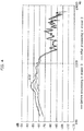
- FIG. 3 is a graph illustrating the frequency characteristics of the signal, which represents the voice of the driver obtained by the microphone 11 installed in the driver's seat, before and after the processing by the eraser when the delayer delays a corresponding signal by 0 msec in the embodiment according to the present disclosure.
- a line 100 represents the frequency characteristics of the first signal not processed by the eraser 3 when the delayer 4a delays the second signal by 0 msec.
- a line 101 represents the frequency characteristics of the first signal processed by the eraser 3 when the delayer 4a delays the second signal by 0 msec.
- the line 101 has a value lower than that of the line 100 at a frequency ranging from about 100 Hz to about 10000 Hz.
- the eraser 3 undesirably suppresses the first signal. This occurs because the second signal includes a signal having the same waveform as that of the first signal, and the erasing of the noises estimated using the second signal results in the suppression of the first signal.
- the voice obtained by the microphone 12 installed in the passenger's seat is used to suppress noises in the voice obtained by the microphone 11 installed in the driver's seat.
- the voice produced by the driver is subjected to reflection inside the cabin of the vehicle, and is mixed in the voice obtained by the microphone 12 installed in the passenger's seat.
- the voice of the driver included in the voice obtained by the microphone 11 installed in the driver's seat is undesirably suppressed.
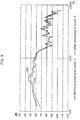
- FIG. 4 is a graph illustrating the frequency characteristics of the signal, which represents the voice of the driver obtained by the microphone 11 installed in the driver's seat, before and after the processing by the eraser when the delayer delays a corresponding signal by 2 msec in the embodiment according to the present disclosure.
- a line 102 represents the frequency characteristics of the first signal not processed by the eraser 3 when the delayer 4a delays the second signal by 2 msec.
- a line 103 represents the frequency characteristics of the first signal processed by the eraser 3 when the delayer 4a delays the second signal by 2 msec. Although the line 103 has a value lower than that of the line 102 at a frequency ranging from about 100 Hz to about 10000 Hz, the difference is smaller than that between the values represented by the line 100 and the line 101 shown in FIG. 3 .
- the delayer 4a delays the second signal by 2 msec and the eraser 3 is operated, the amount of the first signal to be suppressed by the eraser 3 is reduced. This occurs because the signal which is included in the second signal and has the same waveform as that of the first signal is reduced as a result of the delay of the second signal by 2 msec. Accordingly, the suppression of the first signal as a result of the erasing of the noises estimated using the second signal is more significantly reduced than that in the case illustrated in FIG. 3 .
- the delay by 2 msec corresponds to about 60 cm to about 70 cm in terms of the distance of the voice propagating because the sound velocity in the air is about 340 m/sec.
- the time needed for the voice of the driver to reach the microphone 12 is about 2 msec.
- the voice obtained by the microphone 12 installed in the passenger's seat is used to suppress noises in the voice obtained by the microphone 11 installed in the driver's seat.
- the voice produced by the driver is subjected to reflection inside the cabin of the vehicle, and is mixed in the voice obtained by the microphone 12 installed in the passenger's seat.
- the degree of suppression of the voice of the driver included in the voice obtained by the microphone 11 installed in the driver's seat is reduced on the basis of the voice of the driver included in the voice obtained by the microphone 12 installed in the passenger's seat.
- the voice obtained by the microphone 12 installed in the passenger's seat should reach the eraser 3 before the voice obtained by the microphone 11 installed in the driver's seat does.
- the voice obtained by the microphone 12 installed in the passenger's seat cannot reach the eraser 3 before the voice obtained by the microphone 11 installed in the driver's seat does.
- Such a configuration reduces the degree of suppression of the voice of the driver included in the voice obtained by the microphone 11 installed in the driver's seat by the eraser 3 on the basis of the voice of the driver included in the voice obtained by the microphone 12 installed in the passenger's seat.
- FIG. 5 is a graph illustrating the frequency characteristics of the signal, which represents the voice of the driver obtained by the microphone 11 installed in the driver's seat, before and after the processing by the eraser when the delayer delays a corresponding signal by 6 msec in the embodiment according to the present disclosure.
- the line 104 represents the frequency characteristics of the first signal not processed by the eraser 3 when the first signal is delayed by 6 msec.
- the line 105 represents the frequency characteristics of the first signal processed by the eraser 3 when the first signal is delayed by 6 sec.
- the line 105 has a value lower than that in the line 104 at a frequency ranging from about 100 Hz to about 10000 Hz, the difference between the values represented by the line 104 and the line 105 is smaller than that between the values represented by the line 102 and the line 103 shown in FIG. 4 .
- the delayer 4a delays the second signal by 6 msec and the eraser 3 is operated, the amount of the first signal to be suppressed by the eraser 3 is reduced. This occurs because the signal which is included in the second signal and has the same waveform as that of the first signal is reduced by delaying the second signal by 6 msec. Accordingly, by erasing the noises estimated using the second signal, the degree of suppression of the first signal is more significantly reduced than the difference between the values represented by the line 102 and the line 103 shown in FIG. 4 .
- the voice obtained by the microphone 12 installed in the passenger's seat is used to suppress noises in the voice obtained by the microphone 11 installed in the driver's seat.
- the voice produced by the driver is subjected to reflection inside the cabin of the vehicle, and is mixed in the voice obtained by the microphone 12 installed in the passenger's seat.
- 6 msec delaying the signal representing the voice obtained by the microphone 12 installed in the passenger's seat the degree of suppression of the voice of the driver included in the voice obtained by the microphone 11 installed in the driver's seat is more significantly reduced than that in the case of the 2 msec delay, on the basis of the voice of the driver included in the voice obtained by the microphone 12 installed in the passenger's seat.
- the delay of the signal representing the target voice in the delayer results in a reduction in degree of suppression of the signal.
- FIG. 6 is a graph illustrating the frequency characteristics of the signal, which represents the voice of the passenger in the passenger's seat obtained by the microphone 11 installed in the driver's seat, before and after the processing by the eraser when the delayer delays the signal by 0 msec in the embodiment according to the present disclosure.
- a line 106 represents the frequency characteristics of the first signal not processed by the eraser 3 when the first signal is delayed by 0 msec.
- a line 107 represents the frequency characteristics of the first signal processed by the eraser 3 when the first signal is delayed by 0 msec.
- the line 107 has a value about 20 dB lower than that in the line 106 at a frequency ranging from about 100 Hz to about 10000 Hz. In other words, the voice of the passenger in the passenger's seat picked up by the microphone 11 installed in the driver's seat is suppressed.
- the voice obtained by the microphone 12 installed in the passenger's seat is used to suppress noises in the voice obtained by the microphone 11 installed in the driver's seat.
- the voice produced by the passenger in the passenger's seat is mixed in the voice obtained by the microphone 11 installed in the driver's seat directly or after undergoing reflection inside the cabin of the vehicle.
- Such mixed noises are removed from the voice obtained by the microphone 11 installed in the driver's seat, through estimation using the waveform of the signal of the voice obtained by the microphone 12 installed in the passenger's seat.
- the voice obtained by the microphone 11 installed in the driver's seat is about 20 dB suppressed as illustrated in FIG. 6 .
- FIG. 7 is a graph illustrating the frequency characteristics of the signal, which represents the voice of the passenger in the passenger's seat obtained by the microphone 11 installed in the driver's seat, before and after the processing by the eraser when the delayer delays the signal by 2 msec in the embodiment according to the present disclosure.
- a line 108 represents the frequency characteristics of the first signal not processed by the eraser 3 when the first signal is delayed by 2 msec.
- a line 109 represents the frequency characteristics of the first signal processed by the eraser 3 when the first signal is delayed by 2 msec.
- the line 109 has a value lower than that in the line 108 at a frequency ranging from about 100 Hz to about 10000 Hz. However, the amount of the first signal suppressed shown in FIG. 7 is more significantly reduced than that shown in FIG. 6 .
- the voice obtained by the microphone 12 installed in the passenger's seat is used to suppress noises in the voice obtained by the microphone 11 installed in the driver's seat.
- the voice produced by the passenger in the passenger's seat is mixed in the voice obtained by the microphone 11 installed in the driver's seat directly or after undergoing reflection inside the cabin of the vehicle.
- Such mixed noises are removed from the voice obtained by the microphone 11 installed in the driver's seat, through estimation using the waveform of the signal of the voice obtained by the microphone 12 installed in the passenger's seat. As illustrated in FIG.
- the degree of suppression of the voice obtained by the microphone 11 installed in the driver's seat is more significantly reduced than in the case where the signal representing the voice obtained by the microphone 12 installed in the passenger's seat is delayed by 0 msec. It is desirable that the signal representing the voice obtained by the microphone 12 installed in the passenger's seat should not delayed, to estimate the voice of the passenger in the passenger's seat mixed in the voice obtained by the microphone 11 installed in the driver's seat as noises and suppress the noises in the voice obtained by the microphone 11 installed in the driver's seat.
- FIG. 8 is a graph illustrating the frequency characteristics of the signal, which represents the voice of the passenger in the passenger's seat obtained by the microphone 11 installed in the driver's seat, before and after the processing by the eraser when the delayer delays the signal by 6 msec in the embodiment according to the present disclosure.
- a line 110 represents the frequency characteristics of the first signal not processed by the eraser 3 when the first signal is delayed by 6 msec.
- a line 111 represents the frequency characteristics of the first signal processed by the eraser 3 when the first signal is delayed by 6 msec.
- the line 111 has a value lower than that in the line 110 at a frequency ranging from about 100 Hz to about 10000 Hz. However, the amount of suppression shown in FIG. 8 is more significantly reduced than that shown in FIG. 7 .
- the voice obtained by the microphone 12 installed in the passenger's seat is used to suppress noises in the voice obtained by the microphone 11 installed in the driver's seat.
- the voice produced by the passenger in the passenger's seat is mixed in the voice obtained by the microphone 11 installed in the driver's seat directly or after undergoing reflection inside the cabin of the vehicle.
- Such mixed noises are removed from the voice obtained by the microphone 11 installed in the driver's seat, through estimation using the waveform of the signal of the voice obtained by the microphone 12 installed in the passenger's seat. As illustrated in FIG.
- the degree of suppression of the voice obtained by the microphone 11 installed in the driver's seat is more significantly reduced than in the case where the signal representing the voice obtained by the microphone 12 installed in the passenger's seat is delayed by 0 msec and the case where the signal representing the voice obtained by the microphone 12 installed in the passenger's seat is delayed by 2 msec. It is desirable that the signal representing the voice obtained by the microphone 12 installed in the passenger's seat should not delayed, to estimate the voice of the passenger in the passenger's seat mixed in the voice obtained by the microphone 11 installed in the driver's seat as noises and suppress the noises in the voice obtained by the microphone 11 installed in the driver's seat.
- the delay of the signal representing a voice as one of noises in the delayer 4a results in a reduction in degree of suppression of noises. Accordingly, to suppress the signal representing the voice as one of noises in the delayer 4a, it is desirable that the signal should not be delayed for a time beyond a predetermined time.
- the signal should be delayed at a predetermined time or longer. It should be noted, as described above, that the times to delay the signal are set by the delayers 4a, 4b, and 4c so as not to exceed the times taken for the voice to propagate in the spaces between the microphone 11 and the microphone 12, the microphone 13, and the microphone 14, respectively.
- the times to delay the signals set by the delayers 4a, 4b, and 4c may be determined on the basis of the trend of suppression of the voice in the signal processing device 1 as shown in FIGs. 3 to 8 .
- FIG. 9 is a diagram illustrating a translation system to which the signal processing system is applied in a modification according to the present disclosure.
- a translation system 20 includes microphones 21a and 21b, a first obtainer 25, a second obtainer 26, a delayer 24 including an adaptive filter 22, and an eraser 23.
- the translation system 20 may further include an information processor which recognizes and translates the voice in which noises are suppressed, and an outputter which outputs the result of translation.
- the first obtainer 25 is wiredly or wirelessly electrically connected with the microphone 21a.
- the first obtainer 25 obtains a first signal of a voice or the like from the microphone 21a.
- the first obtainer 25 receives the signal from the microphone 21a, the signal being converted from the voice obtained by the microphone 21a.
- the second obtainer 26 is wiredly or wirelessly electrically connected with the microphone 21b.
- the second obtainer 26 obtains a second signal of a voice or the like from the microphone 21b.
- the second obtainer 26 receives the signal from the microphone 21b, the signal being converted from the voice obtained by the microphone 21b.
- the first obtainer 25, the second obtainer 26, the delayer 24 including the adaptive filter 22, and the eraser 23 are implemented with processors and memories.
- the functions of the processors and the memories provided by cloud computing may be used.
- the first obtainer 25, the second obtainer 26, and the adaptive filter 22 may be implemented with dedicated circuits, respectively.
- the delayer 24 is wiredly or wirelessly electrically connected with the second obtainer 26.
- the delayer 24 receives a fifth signal obtained by the second obtainer 26, and delays the received signal by a predetermined time.
- the adaptive filter 22 is wiredly or wirelessly electrically connected with the delayer 24.
- the adaptive filter 22 receives the fifth signal delayed by the delayer 24.
- the adaptive filter 22 estimates the noises mixed in the fifth signal obtained by the first obtainer 25.
- the adaptive filter 22 extracts a necessary signal from the received signal through a mathematical filter having a variable coefficient.
- the adaptive filter 22 can calculate a new coefficient through calculation to change the coefficient used in the filter, whenever necessary.
- the eraser 23 is wiredly or wirelessly electrically connected with the first obtainer 25 and the adaptive filter 22.
- the eraser 23 suppresses the noises estimated by the adaptive filter 22 in the fifth signal obtained in the first obtainer 25.
- the translation system 20 is used by a person 30a and a person 30b face-to-face.
- the voice produced by the person 30a is obtained by the first obtainer 25 through the microphone 21a.
- the voice produced by the person 30b is obtained by the second obtainer 26 through the microphone 21b.
- the audio signal obtained by the second obtainer 26 is delayed for a predetermined time by the delayer 24, and is processed by the adaptive filter 22.
- the information of the noises estimated by the adaptive filter 22 then reaches the eraser 23. From the audio signal obtained by the first obtainer 25, the eraser 23 suppresses the noises estimated by the adaptive filter 22.
- the audio signal in which the noises are suppressed undergoes translation processing, and the result thereof is output.
- the translation system 20 can suppress noises, such as the voice produced by the person 30b, in the voice produced by the person 30a.
- the number of the components included in the translation system 20 may be increased compared to the number thereof listed above.
- the system can be used by any number of persons other than 2.
- the translation system 20 according to the modification of the present disclosure may have a configuration allowing use thereof by 3 or more persons.
- the signal processing device 1 and the signal processing method have been described as above according to the embodiment, the signal processing system and the signal processing method are not construed as limitations to the embodiment. A variety of modifications of the present embodiment conceived by a person skilled in the art and embodiments including combinations of components according to different embodiments may also be included in the scope of one or more aspects without departing from the gist of the present disclosure.
- the present disclosure is applicable to a vehicle-installed sound collecting system or a translation system.
Landscapes
- Engineering & Computer Science (AREA)
- Acoustics & Sound (AREA)
- Physics & Mathematics (AREA)
- Signal Processing (AREA)
- Health & Medical Sciences (AREA)
- Audiology, Speech & Language Pathology (AREA)
- Human Computer Interaction (AREA)
- Quality & Reliability (AREA)
- Computational Linguistics (AREA)
- Multimedia (AREA)
- General Health & Medical Sciences (AREA)
- Otolaryngology (AREA)
- Mechanical Engineering (AREA)
- Circuit For Audible Band Transducer (AREA)
- Fittings On The Vehicle Exterior For Carrying Loads, And Devices For Holding Or Mounting Articles (AREA)
- Soundproofing, Sound Blocking, And Sound Damping (AREA)
Abstract
Description
- The present disclosure relates to signal processing devices and signal processing methods.
- As one of vehicle-installed appliances, a sound pickup apparatus is often installed mainly in driver's seats in order to obtain a voice of a driver or the like in vehicles. The sound pickup apparatus enables the driver or the like to perform operations with the voice during use of infotainment or the like. For example, PTL 1 discloses a vehicle-installed sound pickup device and a sound pickup method which can estimate and suppress noises mixed in the target voice such as the voice of the driver, where the noises are voices and the like of others than the voice of the driver.
- PTL 1: Japanese Unexamined Patent Application No.
2017-083600 - However, in the technique disclosed in PTL 1, partial erasing of the target voice unintentionally results in suppression of the target voice in some cases.
- An object of the present disclosure is to suppress noises mixed in a target voice, and prevent the suppression of the target voice.
- The signal processing device according to the present disclosure includes: a first obtainer which obtains a first signal output from a first microphone; a second obtainer which obtains a second signal output from a second microphone installed in a position different from a position where the first microphone is installed; a delayer which delays the second signal; a mixed sounds estimator which estimates noises mixed in the first signal on a basis of the second signal delayed by the delayer; and an eraser which erases the noises from the first signal, the noises being estimated by the mixed sounds estimator.
- The signal processing method according to the present disclosure includes: obtaining a first signal output from a first microphone; obtaining a second signal output from a second microphone installed in a position different from a position where the first microphone is installed; delaying the second signal; estimating noises mixed in the first signal on a basis of the second signal delayed by the delaying; and erasing the noises from the first signal, the noises being estimated in the estimating.
- The signal processing device and the signal processing method according to the present disclosure can suppress mixed sounds, such as a non-target voice mixed in a target voice, and can prevent the suppression of the target voice.
-
- [
FIG. 1 ]
FIG. 1 is a block diagram illustrating a signal processing device according to an embodiment of the present disclosure. - [
FIG. 2 ]
FIG. 2 is a flowchart illustrating an operation of the signal processing device according to the embodiment of the present disclosure. - [
FIG. 3 ]
FIG. 3 is a graph illustrating the frequency characteristics of a signal, which represents a voice of a driver obtained from amicrophone 11 installed in a driver's seat, before and after the processing by an eraser when a delayer delays the signal by 0 msec in the embodiment according to the present disclosure. - [
FIG. 4 ]
FIG. 4 is a graph illustrating the frequency characteristics of a signal, which represents a voice of a driver obtained from amicrophone 11 installed in a driver's seat, before and after the processing by an eraser when a delayer delays the signal by 2 msec in the embodiment according to the present disclosure. - [
FIG. 5 ]
FIG. 5 is a graph illustrating the frequency characteristics of a signal, which represents a voice of a driver obtained from amicrophone 11 installed in a driver's seat, before and after the processing by an eraser when a delayer delays the signal by 6 msec in the embodiment according to the present disclosure. - [
FIG. 6 ]
FIG. 6 is a graph illustrating the frequency characteristics of a signal, which represents a voice of a passenger in a passenger's seat obtained from themicrophone 11 installed in a driver's seat, before and after the processing by the eraser when the delayer delays the signal by 0 msec in the embodiment according to the present disclosure. - [
FIG. 7 ]
FIG. 7 is a graph illustrating the frequency characteristics of a signal, which represents a voice of a passenger in a passenger's seat obtained from themicrophone 11 installed in a driver's seat, before and after the processing by the eraser when the delayer delays the signal by 2 msec in the embodiment according to the present disclosure. - [
FIG. 8 ]
FIG. 8 is a graph illustrating the frequency characteristics of a signal, which represents a voice of a passenger in a passenger's seat obtained from themicrophone 11 installed in a driver's seat, before and after the processing by the eraser when the delayer delays the signal by 6 msec in the embodiment according to the present disclosure. - [
FIG. 9 ]
FIG. 9 is a diagram illustrating a translation system to which the signal processing system according to a modification of the present disclosure is applied. - To estimate noises from a target voice, conventional approaches are used in which a signal obtained from a microphone located in a position spaced from a microphone which obtains the target voice is used to estimate noises picked up by the microphone which obtains the target voice, and to suppress the noises mixed in the target voice. For example, in the case where it is desired to obtain the voice of the driver from a microphone installed in the driver's seat, the voice produced by the passenger in a seat other than the driver's seat and included in the voice obtained by the microphone installed in the driver's seat should be specified. For this reason, the voice of the passenger in the seat other than the driver's seat mixed in the voice obtained by the microphone installed in the driver's seat is specified using the voices obtained by the microphones installed in the seats other than the driver's seat, respectively. To use this approach, the operation of the sound pickup apparatuses installed in the respective seats, such as the microphones, should be controlled in synchronization with the timings of the speeches of the passengers. However, it is difficult to determine whether the passengers in the respective seats speak or not. When the operation is controlled from a wrong determination whether the passengers in the seats speak or not, the target voice is undesirably suppressed. Moreover, when the operation is controlled from such a wrong determination whether the passengers in the seats speak or not, the performance to suppress noises mixed in the target voice, such as the voices of other passengers, is also reduced.
- The signal processing device according to one aspect of the present disclosure may include a first obtainer which obtains a first signal output from a first microphone, a second obtainer which obtains a second signal output from a second microphone installed in a position different from a position where the first microphone is installed, a delayer which delays the second signal, a mixed sounds estimator which estimates noises mixed in the first signal on the basis of the second signal delayed by the delayer, and an eraser which erases the noises from the first signal, the noises being estimated by the mixed sounds estimator.
- Thereby, the signal processing device according to one aspect of the present disclosure can suppress the signal representing the voice as one of noises mixed in the target voice without suppressing the signal representing the target voice. Accordingly, the signal processing device according to one aspect of the present disclosure can more accurately recognize the target voice.
- For example, the delayer may delay the second signal by the time determined on the basis of the positional relation between the first microphone and the second microphone.
- Thereby, the signal processing device according to one aspect of the present disclosure can prevent the second signal representing noises from reaching the eraser earlier than the first signal representing the target voice. Accordingly, the signal processing device according to one aspect of the present disclosure can process the first signal, which has already reached the eraser, using the second signal.
- For example, the delayer may delay the second signal on the basis of the frequency component included in the second signal.
- Thereby, the signal processing device according to one aspect of the present disclosure can set a delay time more suitable for the second signal representing noises. Accordingly, the signal processing device according to one aspect of the present disclosure can more effectively suppress the noises mixed in the first signal representing the target voice.
- Moreover, the signal processing method according to one aspect of the present disclosure may include obtaining a first signal output from a first microphone; obtaining a second signal output from a second microphone installed in a position different from a position where the first microphone is installed; delaying the second signal; estimating noises mixed in the first signal on the basis of the second signal delayed in the delaying; and erasing the noises from the first signal, the noises being estimated in the estimating.
- Thereby, the signal processing method according to one aspect of the present disclosure can suppress the signal representing the voice as one of noises mixed in the target voice without suppressing the signal representing the target voice. Accordingly, the signal processing device according to one aspect of the present disclosure enables more accurate recognition of the target voice.
- An embodiment will now be specifically described with reference to the drawings.
-
FIG. 1 is a block diagram illustrating a signal processing device according to an embodiment of the present disclosure. A signal processing device 1 according to the embodiment of the present disclosure includesmicrophones first obtainer 15, asecond obtainer 16, a third obtainer 17, afourth obtainer 18,delayers mixed sounds estimator 2 includingadaptive filters eraser 3. - The
microphones - The
first obtainer 15 is wiredly or wirelessly electrically connected with themicrophone 11. Thefirst obtainer 15 receives the signal from themicrophone 11, the signal being converted from the voice obtained by themicrophone 11. Thefirst obtainer 15 has no delayer. - The
second obtainer 16 is wiredly or wirelessly electrically connected with themicrophone 12. Thesecond obtainer 16 receives the signal from themicrophone 12, the signal being converted from the voice obtained by themicrophone 12. - The
third obtainer 17 is wiredly or wirelessly electrically connected with themicrophone 13. Thethird obtainer 17 receives the signal from themicrophone 13, the signal being converted from the voice obtained by themicrophone 13. - The
fourth obtainer 18 is wiredly or wirelessly electrically connected with themicrophone 14. Thefourth obtainer 18 receives the signal from themicrophone 14, the signal being converted from the voice obtained by themicrophone 14. - The
first obtainer 15, thesecond obtainer 16, thethird obtainer 17, thefourth obtainer 18, thedelayers mixed sounds estimator 2 including theadaptive filters eraser 3 are implemented with processors and memories. The functions of the processors and the memories provided by cloud computing may be used. Thefirst obtainer 15, thesecond obtainer 16, thethird obtainer 17, thefourth obtainer 18, and theadaptive filters - The
delayer 4a is wiredly or wirelessly electrically connected with thesecond obtainer 16, thedelayer 4b with thethird obtainer 17, and thedelayer 4c with thefourth obtainer 18. Thedelayer 4a, thedelayer 4b, and thedelayer 4c receive the second signal, the third signal, and the fourth signal received by thesecond obtainer 16, thethird obtainer 17, and thefourth obtainer 18, respectively, and delay the received signals by predetermined times, respectively. Here, the expression "delay the signal" means that each of the signals received by thedelayer 4a, thedelayer 4b, and thedelayer 4c is transmitted to themixed sounds estimator 2 after a predetermined time has passed. For example, thedelayer 4a, thedelayer 4b, and the delayer 4c form a group of memories for delaying the signals by predetermined times, where the memories are successively connected to implement a stack. In the group of memories, the obtained signals may be output first in first out (FIFO) to delay the signals. For example, the times to output the signals by thedelayer 4a, thedelayer 4b, and thedelayer 4c each are equal to or less than the value obtained by dividing the distance between themicrophone 11 and their corresponding microphone (i.e., themicrophone 12, themicrophone 13, and the microphone 14) by the sound velocity. - The mixed sounds
estimator 2 includes theadaptive filters estimator 2 is wiredly or wirelessly electrically connected with thedelayer 4a, thedelayer 4b, and thedelayer 4c. The mixed soundsestimator 2 receives the second signal, the third signal, and the fourth signal delayed by thedelayer 4a, thedelayer 4b, and thedelayer 4c, respectively. On the basis of the second signal, the third signal, and the fourth signal, themixed sounds estimator 2 estimates the noises mixed in the first signal obtained by thefirst obtainer 15. - Specifically, the
mixed sounds estimator 2 corrects the filter coefficients of theadaptive filters eraser 3 is non-correlated with or independent from the inputs to theadaptive filters microphone 11. Accordingly, after the filter coefficient of theadaptive filter 2a is corrected such that the signal SO is non-correlated with or independent from the input to theadaptive filter 2a, the signal output from theadaptive filter 2a represents the mixed sounds signal S2' included in the signal S1, the mixed sounds signal S2' representing the mixed sounds which are the voice produced by the passenger P2 and mixed in the voice produced by the passenger P1. - The mixed sounds
estimator 2 may periodically perform the correction processing of the filter coefficient, or may perform the correction processing every time when themicrophones - The
adaptive filters adaptive filters adaptive filters adaptive filters - The
eraser 3 is wiredly or wirelessly electrically connected with thefirst obtainer 15 and themixed sounds estimator 2. Theeraser 3 suppresses the noises estimated by themixed sounds estimator 2, the noises being contained in the first signal obtained by thefirst obtainer 15. - For example, in the signal processing device 1, the
microphone 11 may be installed in the driver's seat of a vehicle, themicrophone 12 may be installed in the passenger's seat of the vehicle, and themicrophones microphone 11 may be installed in the passenger's seat of the vehicle, themicrophone 12 may be installed in the driver's seat of the vehicle, and themicrophones microphone 11 may be installed on the left backseat of the vehicle, themicrophone 12 may be installed in the driver's seat of the vehicle, themicrophone 13 may be installed in the passenger's seat of the vehicle, and themicrophone 14 may be installed on the right backseat of the vehicle. Alternatively, for example, to suppress noises in the voice of the passenger on the right backseat of the vehicle, themicrophone 11 may be installed on the right backseat of the vehicle, themicrophone 12 may be installed in the driver's seat of the vehicle, themicrophone 13 may be installed in the passenger's seat of the vehicle, and themicrophone 14 may be installed on the left backseat of the vehicle. A plurality of such symmetrical signal processing systems may be installed. - The connection relations of the
microphone 11, themicrophone 12, themicrophone 13, and themicrophone 14 with other components in the signal processing device 1 are the same as described above. Themicrophones - The signal processing device 1 may include pluralities of these components described above.
-
FIG. 2 is a flowchart illustrating the operation of the signal processing device according to the embodiment of the present disclosure. The flow of the entire system will now be described with reference to the flowchart. - First, in the signal processing device 1, the
first obtainer 15 and thesecond obtainer 16 obtain the first signal and the second signal from themicrophone 11 and themicrophone 12, respectively (Step S101). At this time, further, thethird obtainer 17 and thefourth obtainer 18 may obtain the third signal and the fourth signal from themicrophone 13 and themicrophone 14, respectively. - Next, in the signal processing device 1, the
delayer 4a delays the second signal received from thesecond obtainer 16 by a predetermined time (Step S102). At this time, further, thedelayer 4b and thedelayer 4c may delay the third signal received from thethird obtainer 17 and the fourth signal received from thefourth obtainer 18 by predetermined times, respectively. - The
delayer 4a, thedelayer 4b, and thedelayer 4c may delay the second signal, the third signal, and the fourth signal for the same period of time, or may delay the second signal, the third signal, and the fourth signal for different periods of time, respectively. The times to delay the second signal, the third signal, and the fourth signal by thedelayer 4a, thedelayer 4b, and thedelayer 4c may be determined according to the positional relations of themicrophone 11 with themicrophone 12, themicrophone 13, and themicrophone 14, respectively. Here, for example, the positional relation indicates a distance to themicrophone 11. For example, the time to delay the signal may be increased as the distance to themicrophone 11 is longer. - The times to delay the second signal, the third signal, and the fourth signal by the
delayer 4a, thedelayer 4b, and thedelayer 4c may be individually determined by the frequencies of the second signal, the third signal, and the fourth signal, respectively. For example, thedelayer 4a specifies the frequency of the second signal by frequency analysis. On the basis of the table having a prepared delay time according to the frequency, thedelayer 4a may determine the time to delay the signal. Thedelayer 4a may also determine the time to delay the signal within the same signal according to the frequency component. The delay of the signal is difficult to effectively act on the low frequency signal because of its long wavelength. For example, experiments have revealed that when the time to delay low frequency signal is set at a predetermined time or longer, the degree of suppressing the first signal is reduced. Accordingly, for example, the time to delay the signal having a low frequency component may be set at a predetermined time or longer, and the signal having a high frequency component may be determined at the predetermined time or shorter. - Alternatively, the time to delay the second signal, the third signal, and the fourth signal by the
delayer 4a, thedelayer 4b, and thedelayer 4c may be determined according to the temperature inside the cabin of the vehicle. - The
delayer 4a, thedelayer 4b, and thedelayer 4c set the times to delay the second signal, the third signal, and the fourth signal so as not to exceed the times taken for the voice to propagate in the spaces between themicrophone 11 and themicrophone 12, themicrophone 13, and themicrophone 14, respectively. For example, in the case where the distance between themicrophone 11 and themicrophone 12 is 1 m and the time for the voice to propagate in the space between themicrophone 11 and themicrophone 12 is 3 msec, thedelayer 4a sets a delay time of 3 msec or less for the second signal. - Subsequently, in the signal processing device 1, the
mixed sounds estimator 2 estimates noises mixed in the first signal, which is obtained by thefirst obtainer 15, on the basis of the second signal delayed by thedelayer 4a (Step S103). At this time, themixed sounds estimator 2 may further estimate noises mixed in the first signal, which is obtained by thefirst obtainer 15, on the basis of the third signal and the fourth signal delayed by thedelayer 4b and thedelayer 4c, respectively. - In the signal processing device 1, the
eraser 3 suppresses the noises in the first signal, which are estimated by the mixed sounds estimator 2 (Step S104). - The state of the signal processed in the signal processing device 1 will now be described with reference to
FIGs. 3 to 8 . - In the signal processing device 1, the estimation of the signals representing the target voice as a noise can be prevented by delaying the signals obtained by the
second obtainer 16, thethird obtainer 17, and thefourth obtainer 18 for suitable times, where the signals representing the target voice are included in the signals which represent voices and are obtained by thesecond obtainer 16, thethird obtainer 17, and thefourth obtainer 18, respectively. The signals representing the target voice included in the signals, which represent voices and are obtained by thesecond obtainer 16, thethird obtainer 17, and thefourth obtainer 18, respectively, reach theeraser 3 behind the signal representing the target voice obtained by thefirst obtainer 15. Such a configuration does not cause theeraser 3 to suppress the target voice obtained by thefirst obtainer 15 on the basis of the signals representing the target voice included in the signals which represent voices and are obtained by thesecond obtainer 16, thethird obtainer 17, and thefourth obtainer 18, respectively. -
FIG. 3 is a graph illustrating the frequency characteristics of the signal, which represents the voice of the driver obtained by themicrophone 11 installed in the driver's seat, before and after the processing by the eraser when the delayer delays a corresponding signal by 0 msec in the embodiment according to the present disclosure. Aline 100 represents the frequency characteristics of the first signal not processed by theeraser 3 when thedelayer 4a delays the second signal by 0 msec. Aline 101 represents the frequency characteristics of the first signal processed by theeraser 3 when thedelayer 4a delays the second signal by 0 msec. Theline 101 has a value lower than that of theline 100 at a frequency ranging from about 100 Hz to about 10000 Hz. In other words, when thedelayer 4a delays the second signal by 0 msec and theeraser 3 is operated, theeraser 3 undesirably suppresses the first signal. This occurs because the second signal includes a signal having the same waveform as that of the first signal, and the erasing of the noises estimated using the second signal results in the suppression of the first signal. - For example, consider the case where the voice obtained by the
microphone 12 installed in the passenger's seat is used to suppress noises in the voice obtained by themicrophone 11 installed in the driver's seat. The voice produced by the driver is subjected to reflection inside the cabin of the vehicle, and is mixed in the voice obtained by themicrophone 12 installed in the passenger's seat. On the basis of the voice of the driver mixed in the voice obtained by themicrophone 12 installed in the passenger's seat, the voice of the driver included in the voice obtained by themicrophone 11 installed in the driver's seat is undesirably suppressed. -
FIG. 4 is a graph illustrating the frequency characteristics of the signal, which represents the voice of the driver obtained by themicrophone 11 installed in the driver's seat, before and after the processing by the eraser when the delayer delays a corresponding signal by 2 msec in the embodiment according to the present disclosure. Aline 102 represents the frequency characteristics of the first signal not processed by theeraser 3 when thedelayer 4a delays the second signal by 2 msec. Aline 103 represents the frequency characteristics of the first signal processed by theeraser 3 when thedelayer 4a delays the second signal by 2 msec. Although theline 103 has a value lower than that of theline 102 at a frequency ranging from about 100 Hz to about 10000 Hz, the difference is smaller than that between the values represented by theline 100 and theline 101 shown inFIG. 3 . - In other words, when the
delayer 4a delays the second signal by 2 msec and theeraser 3 is operated, the amount of the first signal to be suppressed by theeraser 3 is reduced. This occurs because the signal which is included in the second signal and has the same waveform as that of the first signal is reduced as a result of the delay of the second signal by 2 msec. Accordingly, the suppression of the first signal as a result of the erasing of the noises estimated using the second signal is more significantly reduced than that in the case illustrated inFIG. 3 . - Here, the delay by 2 msec corresponds to about 60 cm to about 70 cm in terms of the distance of the voice propagating because the sound velocity in the air is about 340 m/sec. In other words, in the case where the
microphones microphone 12 is about 2 msec. - For example, consider the case where the voice obtained by the
microphone 12 installed in the passenger's seat is used to suppress noises in the voice obtained by themicrophone 11 installed in the driver's seat. The voice produced by the driver is subjected to reflection inside the cabin of the vehicle, and is mixed in the voice obtained by themicrophone 12 installed in the passenger's seat. However, by 2 msec delaying the signal representing the voice obtained by themicrophone 12 installed in the passenger's seat, the degree of suppression of the voice of the driver included in the voice obtained by themicrophone 11 installed in the driver's seat is reduced on the basis of the voice of the driver included in the voice obtained by themicrophone 12 installed in the passenger's seat. For theeraser 3 to suppress the voice of the driver included in the voice obtained by themicrophone 11 installed in the driver's seat on the basis of the voice of the driver included in the voice obtained by themicrophone 12 installed in the passenger's seat, the voice obtained by themicrophone 12 installed in the passenger's seat should reach theeraser 3 before the voice obtained by themicrophone 11 installed in the driver's seat does. However, by delaying the voice obtained by themicrophone 12 installed in the passenger's seat, the voice obtained by themicrophone 12 installed in the passenger's seat cannot reach theeraser 3 before the voice obtained by themicrophone 11 installed in the driver's seat does. Such a configuration reduces the degree of suppression of the voice of the driver included in the voice obtained by themicrophone 11 installed in the driver's seat by theeraser 3 on the basis of the voice of the driver included in the voice obtained by themicrophone 12 installed in the passenger's seat. -
FIG. 5 is a graph illustrating the frequency characteristics of the signal, which represents the voice of the driver obtained by themicrophone 11 installed in the driver's seat, before and after the processing by the eraser when the delayer delays a corresponding signal by 6 msec in the embodiment according to the present disclosure. Theline 104 represents the frequency characteristics of the first signal not processed by theeraser 3 when the first signal is delayed by 6 msec. Theline 105 represents the frequency characteristics of the first signal processed by theeraser 3 when the first signal is delayed by 6 sec. Although theline 105 has a value lower than that in theline 104 at a frequency ranging from about 100 Hz to about 10000 Hz, the difference between the values represented by theline 104 and theline 105 is smaller than that between the values represented by theline 102 and theline 103 shown inFIG. 4 . - In other words, when the
delayer 4a delays the second signal by 6 msec and theeraser 3 is operated, the amount of the first signal to be suppressed by theeraser 3 is reduced. This occurs because the signal which is included in the second signal and has the same waveform as that of the first signal is reduced by delaying the second signal by 6 msec. Accordingly, by erasing the noises estimated using the second signal, the degree of suppression of the first signal is more significantly reduced than the difference between the values represented by theline 102 and theline 103 shown inFIG. 4 . - For example, consider the case where the voice obtained by the
microphone 12 installed in the passenger's seat is used to suppress noises in the voice obtained by themicrophone 11 installed in the driver's seat. The voice produced by the driver is subjected to reflection inside the cabin of the vehicle, and is mixed in the voice obtained by themicrophone 12 installed in the passenger's seat. However, by 6 msec delaying the signal representing the voice obtained by themicrophone 12 installed in the passenger's seat, the degree of suppression of the voice of the driver included in the voice obtained by themicrophone 11 installed in the driver's seat is more significantly reduced than that in the case of the 2 msec delay, on the basis of the voice of the driver included in the voice obtained by themicrophone 12 installed in the passenger's seat. - As shown in
FIGs. 3 ,4 , and5 , the delay of the signal representing the target voice in the delayer results in a reduction in degree of suppression of the signal. -
FIG. 6 is a graph illustrating the frequency characteristics of the signal, which represents the voice of the passenger in the passenger's seat obtained by themicrophone 11 installed in the driver's seat, before and after the processing by the eraser when the delayer delays the signal by 0 msec in the embodiment according to the present disclosure. Aline 106 represents the frequency characteristics of the first signal not processed by theeraser 3 when the first signal is delayed by 0 msec. Aline 107 represents the frequency characteristics of the first signal processed by theeraser 3 when the first signal is delayed by 0 msec. Theline 107 has a value about 20 dB lower than that in theline 106 at a frequency ranging from about 100 Hz to about 10000 Hz. In other words, the voice of the passenger in the passenger's seat picked up by themicrophone 11 installed in the driver's seat is suppressed. - For example, consider the case where the voice obtained by the
microphone 12 installed in the passenger's seat is used to suppress noises in the voice obtained by themicrophone 11 installed in the driver's seat. The voice produced by the passenger in the passenger's seat is mixed in the voice obtained by themicrophone 11 installed in the driver's seat directly or after undergoing reflection inside the cabin of the vehicle. Such mixed noises are removed from the voice obtained by themicrophone 11 installed in the driver's seat, through estimation using the waveform of the signal of the voice obtained by themicrophone 12 installed in the passenger's seat. In the case where the signal representing the voice obtained by themicrophone 12 installed in the passenger's seat is delayed by 0 msec, the voice obtained by themicrophone 11 installed in the driver's seat is about 20 dB suppressed as illustrated inFIG. 6 . -
FIG. 7 is a graph illustrating the frequency characteristics of the signal, which represents the voice of the passenger in the passenger's seat obtained by themicrophone 11 installed in the driver's seat, before and after the processing by the eraser when the delayer delays the signal by 2 msec in the embodiment according to the present disclosure. Aline 108 represents the frequency characteristics of the first signal not processed by theeraser 3 when the first signal is delayed by 2 msec. Aline 109 represents the frequency characteristics of the first signal processed by theeraser 3 when the first signal is delayed by 2 msec. Theline 109 has a value lower than that in theline 108 at a frequency ranging from about 100 Hz to about 10000 Hz. However, the amount of the first signal suppressed shown inFIG. 7 is more significantly reduced than that shown inFIG. 6 . - For example, consider the case where the voice obtained by the
microphone 12 installed in the passenger's seat is used to suppress noises in the voice obtained by themicrophone 11 installed in the driver's seat. As described above, the voice produced by the passenger in the passenger's seat is mixed in the voice obtained by themicrophone 11 installed in the driver's seat directly or after undergoing reflection inside the cabin of the vehicle. Such mixed noises are removed from the voice obtained by themicrophone 11 installed in the driver's seat, through estimation using the waveform of the signal of the voice obtained by themicrophone 12 installed in the passenger's seat. As illustrated inFIG. 7 , in the case where the signal representing the voice obtained by themicrophone 12 installed in the passenger's seat is delayed by 2 msec, the degree of suppression of the voice obtained by themicrophone 11 installed in the driver's seat is more significantly reduced than in the case where the signal representing the voice obtained by themicrophone 12 installed in the passenger's seat is delayed by 0 msec. It is desirable that the signal representing the voice obtained by themicrophone 12 installed in the passenger's seat should not delayed, to estimate the voice of the passenger in the passenger's seat mixed in the voice obtained by themicrophone 11 installed in the driver's seat as noises and suppress the noises in the voice obtained by themicrophone 11 installed in the driver's seat. -
FIG. 8 is a graph illustrating the frequency characteristics of the signal, which represents the voice of the passenger in the passenger's seat obtained by themicrophone 11 installed in the driver's seat, before and after the processing by the eraser when the delayer delays the signal by 6 msec in the embodiment according to the present disclosure. Aline 110 represents the frequency characteristics of the first signal not processed by theeraser 3 when the first signal is delayed by 6 msec. Aline 111 represents the frequency characteristics of the first signal processed by theeraser 3 when the first signal is delayed by 6 msec. Theline 111 has a value lower than that in theline 110 at a frequency ranging from about 100 Hz to about 10000 Hz. However, the amount of suppression shown inFIG. 8 is more significantly reduced than that shown inFIG. 7 . - For example, consider the case where the voice obtained by the
microphone 12 installed in the passenger's seat is used to suppress noises in the voice obtained by themicrophone 11 installed in the driver's seat. As described above, the voice produced by the passenger in the passenger's seat is mixed in the voice obtained by themicrophone 11 installed in the driver's seat directly or after undergoing reflection inside the cabin of the vehicle. Such mixed noises are removed from the voice obtained by themicrophone 11 installed in the driver's seat, through estimation using the waveform of the signal of the voice obtained by themicrophone 12 installed in the passenger's seat. As illustrated inFIG. 8 , in the case where the signal representing the voice obtained by themicrophone 12 installed in the passenger's seat is delayed by 6 msec, the degree of suppression of the voice obtained by themicrophone 11 installed in the driver's seat is more significantly reduced than in the case where the signal representing the voice obtained by themicrophone 12 installed in the passenger's seat is delayed by 0 msec and the case where the signal representing the voice obtained by themicrophone 12 installed in the passenger's seat is delayed by 2 msec. It is desirable that the signal representing the voice obtained by themicrophone 12 installed in the passenger's seat should not delayed, to estimate the voice of the passenger in the passenger's seat mixed in the voice obtained by themicrophone 11 installed in the driver's seat as noises and suppress the noises in the voice obtained by themicrophone 11 installed in the driver's seat. - As shown in
FIGs. 6 ,7 , and8 , the delay of the signal representing a voice as one of noises in thedelayer 4a results in a reduction in degree of suppression of noises. Accordingly, to suppress the signal representing the voice as one of noises in thedelayer 4a, it is desirable that the signal should not be delayed for a time beyond a predetermined time. - Conversely, not to suppress the target voice, as shown in
FIGs. 3 ,4 , and5 , it is desirable that the signal should be delayed at a predetermined time or longer. It should be noted, as described above, that the times to delay the signal are set by thedelayers microphone 11 and themicrophone 12, themicrophone 13, and themicrophone 14, respectively. - The times to delay the signals set by the
delayers FIGs. 3 to 8 . - The signal processing device 1 above can also be applied to a
translation system 20 which recognizes the voice of a speaker, translates the speech into another language, and outputs the translation.FIG. 9 is a diagram illustrating a translation system to which the signal processing system is applied in a modification according to the present disclosure. As illustrated inFIG. 9 , atranslation system 20 includesmicrophones first obtainer 25, asecond obtainer 26, adelayer 24 including anadaptive filter 22, and aneraser 23. Thetranslation system 20 may further include an information processor which recognizes and translates the voice in which noises are suppressed, and an outputter which outputs the result of translation. - The
first obtainer 25 is wiredly or wirelessly electrically connected with themicrophone 21a. Thefirst obtainer 25 obtains a first signal of a voice or the like from themicrophone 21a. Thefirst obtainer 25 receives the signal from themicrophone 21a, the signal being converted from the voice obtained by themicrophone 21a. - The
second obtainer 26 is wiredly or wirelessly electrically connected with themicrophone 21b. Thesecond obtainer 26 obtains a second signal of a voice or the like from themicrophone 21b. Thesecond obtainer 26 receives the signal from themicrophone 21b, the signal being converted from the voice obtained by themicrophone 21b. - The
first obtainer 25, thesecond obtainer 26, thedelayer 24 including theadaptive filter 22, and theeraser 23 are implemented with processors and memories. The functions of the processors and the memories provided by cloud computing may be used. Thefirst obtainer 25, thesecond obtainer 26, and theadaptive filter 22 may be implemented with dedicated circuits, respectively. - The
delayer 24 is wiredly or wirelessly electrically connected with thesecond obtainer 26. Thedelayer 24 receives a fifth signal obtained by thesecond obtainer 26, and delays the received signal by a predetermined time. - The
adaptive filter 22 is wiredly or wirelessly electrically connected with thedelayer 24. Theadaptive filter 22 receives the fifth signal delayed by thedelayer 24. On the basis of the fifth signal, theadaptive filter 22 estimates the noises mixed in the fifth signal obtained by thefirst obtainer 25. - The
adaptive filter 22 extracts a necessary signal from the received signal through a mathematical filter having a variable coefficient. Theadaptive filter 22 can calculate a new coefficient through calculation to change the coefficient used in the filter, whenever necessary. - The
eraser 23 is wiredly or wirelessly electrically connected with thefirst obtainer 25 and theadaptive filter 22. Theeraser 23 suppresses the noises estimated by theadaptive filter 22 in the fifth signal obtained in thefirst obtainer 25. - It is supposed that the
translation system 20 according to the modification of the present disclosure is used by aperson 30a and aperson 30b face-to-face. In thetranslation system 20, the voice produced by theperson 30a is obtained by thefirst obtainer 25 through themicrophone 21a. In thetranslation system 20, the voice produced by theperson 30b is obtained by thesecond obtainer 26 through themicrophone 21b. The audio signal obtained by thesecond obtainer 26 is delayed for a predetermined time by thedelayer 24, and is processed by theadaptive filter 22. The information of the noises estimated by theadaptive filter 22 then reaches theeraser 23. From the audio signal obtained by thefirst obtainer 25, theeraser 23 suppresses the noises estimated by theadaptive filter 22. - The audio signal in which the noises are suppressed undergoes translation processing, and the result thereof is output. Thus, the
translation system 20 can suppress noises, such as the voice produced by theperson 30b, in the voice produced by theperson 30a. The number of the components included in thetranslation system 20 may be increased compared to the number thereof listed above. Although it is supposed that two persons use thetranslation system 20 according to the modification of the present disclosure, the system can be used by any number of persons other than 2. Thetranslation system 20 according to the modification of the present disclosure may have a configuration allowing use thereof by 3 or more persons. - These general or specific aspects may be implemented with a system, a method, an integrated circuit, a computer program, or a recording medium such as a computer-readable CD-ROM, or may be implemented with any combination of a system, a method, an integrated circuit, a computer program, and a recording medium.
- Although the signal processing device 1 and the signal processing method have been described as above according to the embodiment, the signal processing system and the signal processing method are not construed as limitations to the embodiment. A variety of modifications of the present embodiment conceived by a person skilled in the art and embodiments including combinations of components according to different embodiments may also be included in the scope of one or more aspects without departing from the gist of the present disclosure.
- Although the present invention has been described and illustrated in detail, it is clearly understood that the same is by way of example only and is not to be taken by way of limitation, the scope of the present invention being limited only by the terms of the appended claims.
- The present disclosure is applicable to a vehicle-installed sound collecting system or a translation system.
-
- 1 signal processing device
- 2 mixed sounds estimator
- 2a, 2b, 2c, 22 adaptive filter
- 3, 23 eraser
- 4a, 4b, 4c, 24 delayer
- 11, 12, 13, 14, 21a, 21b microphone
- 15, 25 first obtainer
- 16, 26 second obtainer
- 17 third obtainer
- 18 fourth obtainer
- 20 translation system
- 30a, 30b person
- 100, 101, 102, 103, 104, 105, 106, 107, 108, 109, 110, 111 line
Claims (4)
- A signal processing device, comprising:a first obtainer which obtains a first signal output from a first microphone;a second obtainer which obtains a second signal output from a second microphone installed in a position different from a position where the first microphone is installed;a delayer which delays the second signal;a mixed sounds estimator which estimates noises mixed in the first signal on a basis of the second signal delayed by the delayer; andan eraser which erases the noises from the first signal, the noises being estimated by the mixed sounds estimator.
- The signal processing device according to claim 1,
wherein the delayer delays the second signal by a time determined on a basis of a positional relation between the first microphone and the second microphone. - The signal processing device according to claim 1 or 2,
wherein the delayer delays the second signal on a basis of a frequency component included in the second signal. - A signal processing method, comprising:obtaining a first signal output from a first microphone;obtaining a second signal output from a second microphone installed in a position different from a position where the first microphone is installed;delaying the second signal;estimating noises mixed in the first signal on a basis of the second signal delayed by the delaying; anderasing the noises from the first signal, the noises being estimated in the estimating.
Applications Claiming Priority (1)
| Application Number | Priority Date | Filing Date | Title |
|---|---|---|---|
| JP2019040131A JP7628388B2 (en) | 2019-03-06 | 2019-03-06 | Signal processing device and signal processing method |
Publications (1)
| Publication Number | Publication Date |
|---|---|
| EP3706124A1 true EP3706124A1 (en) | 2020-09-09 |
Family
ID=69845074
Family Applications (1)
| Application Number | Title | Priority Date | Filing Date |
|---|---|---|---|
| EP20159300.1A Ceased EP3706124A1 (en) | 2019-03-06 | 2020-02-25 | Signal processing device and signal processing method |
Country Status (4)
| Country | Link |
|---|---|
| US (1) | US11323802B2 (en) |
| EP (1) | EP3706124A1 (en) |
| JP (2) | JP7628388B2 (en) |
| CN (1) | CN111667845B (en) |
Families Citing this family (2)
| Publication number | Priority date | Publication date | Assignee | Title |
|---|---|---|---|---|
| USD691112S1 (en) * | 2012-01-09 | 2013-10-08 | Beats Electronics, Llc | Gaming headset |
| CN114464203B (en) * | 2022-01-18 | 2022-10-25 | 小米汽车科技有限公司 | Noise filtering method, device, system, vehicle and storage medium |
Citations (2)
| Publication number | Priority date | Publication date | Assignee | Title |
|---|---|---|---|---|
| US8682658B2 (en) * | 2011-06-01 | 2014-03-25 | Parrot | Audio equipment including means for de-noising a speech signal by fractional delay filtering, in particular for a “hands-free” telephony system |
| JP2017083600A (en) | 2015-10-27 | 2017-05-18 | パナソニックIpマネジメント株式会社 | In-vehicle sound collection device and sound collection method |
Family Cites Families (18)
| Publication number | Priority date | Publication date | Assignee | Title |
|---|---|---|---|---|
| JP3301445B2 (en) * | 1992-08-25 | 2002-07-15 | ソニー株式会社 | Voice input device |
| JP3541339B2 (en) * | 1997-06-26 | 2004-07-07 | 富士通株式会社 | Microphone array device |
| US7146013B1 (en) * | 1999-04-28 | 2006-12-05 | Alpine Electronics, Inc. | Microphone system |
| US6584203B2 (en) * | 2001-07-18 | 2003-06-24 | Agere Systems Inc. | Second-order adaptive differential microphone array |
| JP4219611B2 (en) | 2002-05-01 | 2009-02-04 | 独立行政法人理化学研究所 | Noise removal system and noise removal method |
| FR2898209B1 (en) * | 2006-03-01 | 2008-12-12 | Parrot Sa | METHOD FOR DEBRUCTING AN AUDIO SIGNAL |
| EP1994788B1 (en) * | 2006-03-10 | 2014-05-07 | MH Acoustics, LLC | Noise-reducing directional microphone array |
| JP2008022515A (en) * | 2006-06-14 | 2008-01-31 | Matsushita Electric Works Ltd | Speech apparatus |
| US7983428B2 (en) * | 2007-05-09 | 2011-07-19 | Motorola Mobility, Inc. | Noise reduction on wireless headset input via dual channel calibration within mobile phone |
| US9473850B2 (en) * | 2007-07-19 | 2016-10-18 | Alon Konchitsky | Voice signals improvements in compressed wireless communications systems |
| JP5862349B2 (en) * | 2012-02-16 | 2016-02-16 | 株式会社Jvcケンウッド | Noise reduction device, voice input device, wireless communication device, and noise reduction method |
| EP2848007B1 (en) * | 2012-10-15 | 2021-03-17 | MH Acoustics, LLC | Noise-reducing directional microphone array |
| JP6198432B2 (en) | 2013-04-09 | 2017-09-20 | 小島プレス工業株式会社 | Voice recognition control device |
| JP2015014675A (en) | 2013-07-04 | 2015-01-22 | 株式会社日立システムズ | Speech recognition apparatus, method, program, system, and terminal |
| WO2016114988A2 (en) * | 2015-01-12 | 2016-07-21 | Mh Acoustics, Llc | Reverberation suppression using multiple beamformers |
| US10028051B2 (en) * | 2015-08-31 | 2018-07-17 | Panasonic Intellectual Property Management Co., Ltd. | Sound source localization apparatus |
| EP3333850A4 (en) | 2015-10-16 | 2018-06-27 | Panasonic Intellectual Property Management Co., Ltd. | Sound source separating device and sound source separating method |
| JP6670224B2 (en) * | 2016-11-14 | 2020-03-18 | 株式会社日立製作所 | Audio signal processing system |
-
2019
- 2019-03-06 JP JP2019040131A patent/JP7628388B2/en active Active
-
2020
- 2020-02-25 EP EP20159300.1A patent/EP3706124A1/en not_active Ceased
- 2020-03-02 US US16/806,190 patent/US11323802B2/en active Active
- 2020-03-03 CN CN202010138125.6A patent/CN111667845B/en active Active
-
2024
- 2024-01-11 JP JP2024002391A patent/JP7692069B2/en active Active
Patent Citations (2)
| Publication number | Priority date | Publication date | Assignee | Title |
|---|---|---|---|---|
| US8682658B2 (en) * | 2011-06-01 | 2014-03-25 | Parrot | Audio equipment including means for de-noising a speech signal by fractional delay filtering, in particular for a “hands-free” telephony system |
| JP2017083600A (en) | 2015-10-27 | 2017-05-18 | パナソニックIpマネジメント株式会社 | In-vehicle sound collection device and sound collection method |
Non-Patent Citations (2)
| Title |
|---|
| AARTI SINGH: "Adaptive Noise Cancellation", DEPT. OF ELECTRONICS & COMMUNICATION NETAJI SUBHAS, 1 January 1997 (1997-01-01), XP055448954, Retrieved from the Internet <URL:www.cs.cmu.edu/~aarti/pubs/ANC.pdf> [retrieved on 20180207] * |
| AKIHIKO SUGIYAMA ET AL: "An adaptive noise canceller with adaptive delay compensation for a distant noise source", 2011 IEEE INTERNATIONAL CONFERENCE ON ACOUSTICS, SPEECH AND SIGNAL PROCESSING : (ICASSP 2011) ; PRAGUE, CZECH REPUBLIC, 22 - 27 MAY 2011, IEEE, PISCATAWAY, NJ, 22 May 2011 (2011-05-22), pages 265 - 268, XP032000725, ISBN: 978-1-4577-0538-0, DOI: 10.1109/ICASSP.2011.5946391 * |
Also Published As
| Publication number | Publication date |
|---|---|
| JP2024026716A (en) | 2024-02-28 |
| US11323802B2 (en) | 2022-05-03 |
| US20200288239A1 (en) | 2020-09-10 |
| JP7628388B2 (en) | 2025-02-10 |
| JP2020144204A (en) | 2020-09-10 |
| CN111667845A (en) | 2020-09-15 |
| JP7692069B2 (en) | 2025-06-12 |
| CN111667845B (en) | 2025-02-25 |
Similar Documents
| Publication | Publication Date | Title |
|---|---|---|
| CN104508737B (en) | The signal transacting related for the noise of the Vehicular communication system with multiple acoustical areas | |
| EP3346683B1 (en) | System and method for echo supression for in-car communication | |
| JP4283212B2 (en) | Noise removal apparatus, noise removal program, and noise removal method | |
| EP2027581B1 (en) | Signal separator, method for determining output signals on the basis of microphone signals, and computer program | |
| CN104737475B (en) | Wind noise detection for the Vehicular communication system with multiple acoustical area | |
| EP2675073A1 (en) | Adaptive equalizer, acoustic echo canceller device, and active noise control device | |
| US20140112496A1 (en) | Microphone placement for noise cancellation in vehicles | |
| EP3276621B1 (en) | Noise suppression device and noise suppressing method | |
| CN108550370B (en) | System and method for feedback control of in-vehicle communications | |
| JP6870078B2 (en) | Noise estimation for dynamic sound adjustment | |
| JP7692069B2 (en) | Signal processing device and signal processing method | |
| US10951978B2 (en) | Output control of sounds from sources respectively positioned in priority and nonpriority directions | |
| EP2490218B1 (en) | Method for interference suppression | |
| Schmid et al. | An expectation-maximization algorithm for multichannel adaptive speech dereverberation in the frequency-domain | |
| EP4064726A1 (en) | Sound pick-up device, sound pick-up method and sound pick-up program | |
| US11122366B2 (en) | Method and apparatus for attenuation of audio howling | |
| US20230274723A1 (en) | Communication support system | |
| EP1351479A1 (en) | Generating an undisturbed signal out of an audio signal including a disturbing signal | |
| Hidri et al. | A microphone array beamforming-based system for multi-talker speech separation |
Legal Events
| Date | Code | Title | Description |
|---|---|---|---|
| PUAI | Public reference made under article 153(3) epc to a published international application that has entered the european phase |
Free format text: ORIGINAL CODE: 0009012 |
|
| STAA | Information on the status of an ep patent application or granted ep patent |
Free format text: STATUS: THE APPLICATION HAS BEEN PUBLISHED |
|
| AK | Designated contracting states |
Kind code of ref document: A1 Designated state(s): AL AT BE BG CH CY CZ DE DK EE ES FI FR GB GR HR HU IE IS IT LI LT LU LV MC MK MT NL NO PL PT RO RS SE SI SK SM TR |
|
| AX | Request for extension of the european patent |
Extension state: BA ME |
|
| STAA | Information on the status of an ep patent application or granted ep patent |
Free format text: STATUS: REQUEST FOR EXAMINATION WAS MADE |
|
| 17P | Request for examination filed |
Effective date: 20210304 |
|
| RBV | Designated contracting states (corrected) |
Designated state(s): AL AT BE BG CH CY CZ DE DK EE ES FI FR GB GR HR HU IE IS IT LI LT LU LV MC MK MT NL NO PL PT RO RS SE SI SK SM TR |
|
| STAA | Information on the status of an ep patent application or granted ep patent |
Free format text: STATUS: EXAMINATION IS IN PROGRESS |
|
| 17Q | First examination report despatched |
Effective date: 20210715 |
|
| STAA | Information on the status of an ep patent application or granted ep patent |
Free format text: STATUS: THE APPLICATION HAS BEEN REFUSED |
|
| 18R | Application refused |
Effective date: 20240521 |