EP3705982B1 - Apparatus and method for adaptively configuring user interface - Google Patents
Apparatus and method for adaptively configuring user interface Download PDFInfo
- Publication number
- EP3705982B1 EP3705982B1 EP18881377.8A EP18881377A EP3705982B1 EP 3705982 B1 EP3705982 B1 EP 3705982B1 EP 18881377 A EP18881377 A EP 18881377A EP 3705982 B1 EP3705982 B1 EP 3705982B1
- Authority
- EP
- European Patent Office
- Prior art keywords
- user
- electronic device
- signal
- display
- input
- Prior art date
- Legal status (The legal status is an assumption and is not a legal conclusion. Google has not performed a legal analysis and makes no representation as to the accuracy of the status listed.)
- Active
Links
Images







Classifications
-
- G—PHYSICS
- G06—COMPUTING OR CALCULATING; COUNTING
- G06F—ELECTRIC DIGITAL DATA PROCESSING
- G06F3/00—Input arrangements for transferring data to be processed into a form capable of being handled by the computer; Output arrangements for transferring data from processing unit to output unit, e.g. interface arrangements
- G06F3/01—Input arrangements or combined input and output arrangements for interaction between user and computer
- G06F3/011—Arrangements for interaction with the human body, e.g. for user immersion in virtual reality
- G06F3/013—Eye tracking input arrangements
-
- G—PHYSICS
- G06—COMPUTING OR CALCULATING; COUNTING
- G06F—ELECTRIC DIGITAL DATA PROCESSING
- G06F3/00—Input arrangements for transferring data to be processed into a form capable of being handled by the computer; Output arrangements for transferring data from processing unit to output unit, e.g. interface arrangements
- G06F3/01—Input arrangements or combined input and output arrangements for interaction between user and computer
- G06F3/011—Arrangements for interaction with the human body, e.g. for user immersion in virtual reality
-
- G—PHYSICS
- G02—OPTICS
- G02B—OPTICAL ELEMENTS, SYSTEMS OR APPARATUS
- G02B27/00—Optical systems or apparatus not provided for by any of the groups G02B1/00 - G02B26/00, G02B30/00
- G02B27/01—Head-up displays
- G02B27/017—Head mounted
-
- G—PHYSICS
- G06—COMPUTING OR CALCULATING; COUNTING
- G06F—ELECTRIC DIGITAL DATA PROCESSING
- G06F3/00—Input arrangements for transferring data to be processed into a form capable of being handled by the computer; Output arrangements for transferring data from processing unit to output unit, e.g. interface arrangements
- G06F3/01—Input arrangements or combined input and output arrangements for interaction between user and computer
- G06F3/03—Arrangements for converting the position or the displacement of a member into a coded form
- G06F3/033—Pointing devices displaced or positioned by the user, e.g. mice, trackballs, pens or joysticks; Accessories therefor
- G06F3/0346—Pointing devices displaced or positioned by the user, e.g. mice, trackballs, pens or joysticks; Accessories therefor with detection of the device orientation or free movement in a three-dimensional [3D] space, e.g. 3D mice, 6-DOF [six degrees of freedom] pointers using gyroscopes, accelerometers or tilt-sensors
-
- G—PHYSICS
- G06—COMPUTING OR CALCULATING; COUNTING
- G06F—ELECTRIC DIGITAL DATA PROCESSING
- G06F3/00—Input arrangements for transferring data to be processed into a form capable of being handled by the computer; Output arrangements for transferring data from processing unit to output unit, e.g. interface arrangements
- G06F3/01—Input arrangements or combined input and output arrangements for interaction between user and computer
- G06F3/03—Arrangements for converting the position or the displacement of a member into a coded form
- G06F3/033—Pointing devices displaced or positioned by the user, e.g. mice, trackballs, pens or joysticks; Accessories therefor
- G06F3/038—Control and interface arrangements therefor, e.g. drivers or device-embedded control circuitry
-
- G—PHYSICS
- G06—COMPUTING OR CALCULATING; COUNTING
- G06F—ELECTRIC DIGITAL DATA PROCESSING
- G06F3/00—Input arrangements for transferring data to be processed into a form capable of being handled by the computer; Output arrangements for transferring data from processing unit to output unit, e.g. interface arrangements
- G06F3/01—Input arrangements or combined input and output arrangements for interaction between user and computer
- G06F3/048—Interaction techniques based on graphical user interfaces [GUI]
- G06F3/0481—Interaction techniques based on graphical user interfaces [GUI] based on specific properties of the displayed interaction object or a metaphor-based environment, e.g. interaction with desktop elements like windows or icons, or assisted by a cursor's changing behaviour or appearance
-
- G—PHYSICS
- G06—COMPUTING OR CALCULATING; COUNTING
- G06F—ELECTRIC DIGITAL DATA PROCESSING
- G06F3/00—Input arrangements for transferring data to be processed into a form capable of being handled by the computer; Output arrangements for transferring data from processing unit to output unit, e.g. interface arrangements
- G06F3/01—Input arrangements or combined input and output arrangements for interaction between user and computer
- G06F3/048—Interaction techniques based on graphical user interfaces [GUI]
- G06F3/0481—Interaction techniques based on graphical user interfaces [GUI] based on specific properties of the displayed interaction object or a metaphor-based environment, e.g. interaction with desktop elements like windows or icons, or assisted by a cursor's changing behaviour or appearance
- G06F3/04812—Interaction techniques based on cursor appearance or behaviour, e.g. being affected by the presence of displayed objects
-
- G—PHYSICS
- G02—OPTICS
- G02B—OPTICAL ELEMENTS, SYSTEMS OR APPARATUS
- G02B27/00—Optical systems or apparatus not provided for by any of the groups G02B1/00 - G02B26/00, G02B30/00
- G02B27/01—Head-up displays
- G02B27/0101—Head-up displays characterised by optical features
- G02B2027/0138—Head-up displays characterised by optical features comprising image capture systems, e.g. camera
-
- G—PHYSICS
- G02—OPTICS
- G02B—OPTICAL ELEMENTS, SYSTEMS OR APPARATUS
- G02B27/00—Optical systems or apparatus not provided for by any of the groups G02B1/00 - G02B26/00, G02B30/00
- G02B27/01—Head-up displays
- G02B27/0101—Head-up displays characterised by optical features
- G02B2027/014—Head-up displays characterised by optical features comprising information/image processing systems
-
- G—PHYSICS
- G06—COMPUTING OR CALCULATING; COUNTING
- G06F—ELECTRIC DIGITAL DATA PROCESSING
- G06F3/00—Input arrangements for transferring data to be processed into a form capable of being handled by the computer; Output arrangements for transferring data from processing unit to output unit, e.g. interface arrangements
- G06F3/01—Input arrangements or combined input and output arrangements for interaction between user and computer
- G06F3/048—Interaction techniques based on graphical user interfaces [GUI]
- G06F3/0481—Interaction techniques based on graphical user interfaces [GUI] based on specific properties of the displayed interaction object or a metaphor-based environment, e.g. interaction with desktop elements like windows or icons, or assisted by a cursor's changing behaviour or appearance
- G06F3/04815—Interaction with a metaphor-based environment or interaction object displayed as three-dimensional [3D], e.g. changing the user viewpoint with respect to the environment or object
Definitions
- Various embodiments relate to an electronic device and a method for adaptively configuring a user interface based on a user's physical characteristic.
- an electronic device may provide various User Experiences (UXs).
- the electronic device may provide a content for a virtual world, that is, Virtual Reality (VR), which is similar to the reality but is not real.
- the electronic device may provide VR, and thus may provide rich experience to a user.
- US 2017/309079 describes a device that can display a visual aura representing contextual information associated with an object that is outside the user's field of view.
- the visual aura can be displayed near an edge of the field of view and can dynamically change as the contextual information associated with the object changes, e.g., the relative position of the object and the user (or the user's field of view) changes.
- US 2017/228036 relates to a multimedia entertainment system that combines both gestures and voice commands to provide an enhanced control scheme.
- a user's body position or motion may be recognized as a gesture, and may be used to provide context to recognize user generated sounds, such as speech input.
- US 2017/329419 relates to a system for combining a gyromouse input with a touch surface input in an augmented reality (AR) environment and/or a virtual reality (VR) environment, a virtual display of virtual items and/or features may be adjusted in response to movement of the gyromouse combined with touch inputs, or touch and drag inputs, received on a touch surface of the gyromouse.
- AR augmented reality
- VR virtual reality
- US 2012/231853 relates to a movement function of a display screen of an information terminal such as a mobile device is controlled in response to a type of user operation to prevent erroneous selection of selectable items and improve operability.
- US 2012/206452 describes a technology for providing realistic occlusion between a virtual object displayed by a head mounted, augmented reality display system and a real object visible to the user's eyes through the display.
- US 2015/070274 describes techniques to allow for a wearable display device, such as a head-mounted display, to be tracked within a 3D space by dynamically generating 6DoF data associated with an orientation and location of the display device within the 3D space.
- the 6DoF data is generated dynamically, in real time, by combining of 3DoF location information and 3DoF orientation information within a user-centered coordinate system.
- DE 20 2017 104403 relates to systems and methods to provide for a determination of whether a particular application is usable by a particular user based on the current physical location of the user.
- the systems and methods can provide the ability to make minor positional adjustments to improve user comfort, and can additionally provide larger positional adjustments to help make the application accessible to the user from the user's current physical position (e.g., standing , sitting, etc.).
- US 2016/375364 describes methods, systems, and computer programs for obtaining profile data of a user from a wearable device.
- One example method includes connecting a peripheral device with a base computing device via a data connection.
- a user who receives a content for VR may have a Field of View (FOV) which is different from another's due to physical characteristics of the users.
- the user, who views a content for VR by using an electronic device which displays a content for VR in a fixed configuration or arrangement, may be inconvenienced due to a difference of a FOV caused by the user's physical characteristic. Therefore, there may be a need for a method for providing a content for VR in a configuration adaptively changed according to the user's physical characteristic.
- a method of an electronic device may include: displaying, on the display, a first UI which guides an action of a user of the electronic device such that an external electronic device grasped by the user is placed at a specific position on the user's body; receiving a first signal, which is transmitted by the external electronic device and is used to determine the user's physical characteristic related to the electronic device and the external electronic device according to the first UI; displaying, on the display, a second UI which guides a subsequent action of the user such that the user's arm is extended; receiving a second signal, which is transmitted by the external electronic device and is used to determine the user's physical characteristic related to the electronic device and the external electronic device, in response to detection of the user input in the external electronic device according to the second UI; and the method further comprising: identifying a distance between a position at which the first signal is received and a position at which the second signal is received, the identified distance comprising an arm span associated with the user; determining the user's physical characteristic
- the electronic device identifies a user's characteristic based on at least one signal received from another electronic device, and thus can provide a user interface optimized for the user.
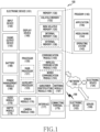
- Fig. 1 is a block diagram illustrating an electronic device 101 in a network environment 100 according to various embodiments.
- the electronic device 101 in the network environment 100 may communicate with an electronic device 102 via a first network 198 (e.g., a short-range wireless communication network), or an electronic device 104 or a server 108 via a second network 199 (e.g., a long-range wireless communication network).
- the electronic device 101 may communicate with the electronic device 104 via the server 108.
- the electronic device 101 may include a processor 120, memory 130, an input device 150, a sound output device 155, a display device 160, an audio module 170, a sensor module 176, an interface 177, a haptic module 179, a camera module 180, a power management module 188, a battery 189, a communication module 190, a subscriber identification module (SIM) 196, or an antenna module 197.
- at least one (e.g., the display device 160 or the camera module 180) of the components may be omitted from the electronic device 101, or one or more other components may be added in the electronic device 101.
- some of the components may be implemented as single integrated circuitry.
- the sensor module 176 e.g., a fingerprint sensor, an iris sensor, or an illuminance sensor
- the display device 160 e.g., a display
- an haptic module 179 e.g., a camera module 180
- a power management module 188 e.g., the display
- the processor 120 may include a main processor 121 (e.g., a central processing unit (CPU) or an application processor (AP)), and an auxiliary processor 123 (e.g., a graphics processing unit (GPU), an image signal processor (ISP), a sensor hub processor, or a communication processor (CP)) that is operable independently from, or in conjunction with, the main processor 121.
- auxiliary processor 123 may be adapted to consume less power than the main processor 121, or to be specific to a specified function.
- the auxiliary processor 123 may be implemented as separate from, or as part of the main processor 121.
- the auxiliary processor 123 may control at least some of functions or states related to at least one component (e.g., the display device 160, the sensor module 176, or the communication module 190) among the components of the electronic device 101, instead of the main processor 121 while the main processor 121 is in an inactive (e.g., sleep) state, or together with the main processor 121 while the main processor 121 is in an active state (e.g., executing an application).
- the auxiliary processor 123 e.g., an image signal processor or a communication processor
- the input device 150 may receive a command or data to be used by other component (e.g., the processor 120) of the electronic device 101, from the outside (e.g., a user) of the electronic device 101.
- the input device 150 may include, for example, a microphone, a mouse, or a keyboard.
- the audio module 170 may convert a sound into an electrical signal and vice versa. According to an embodiment, the audio module 170 may obtain the sound via the input device 150, or output the sound via the sound output device 155 or a headphone of an external electronic device (e.g., an electronic device 102) directly (e.g., wired) or wirelessly coupled with the electronic device 101.
- an external electronic device e.g., an electronic device 102
- directly e.g., wired
- a connecting terminal 178 may include a connector via which the electronic device 101 may be physically connected with the external electronic device (e.g., the electronic device 102).
- the connecting terminal 178 may include, for example, a HDMI connector, a USB connector, a SD card connector, or an audio connector (e.g., a headphone connector),
- the haptic module 179 may convert an electrical signal into a mechanical stimulus (e.g., a vibration or a movement) or electrical stimulus which may be recognized by a user via his tactile sensation or kinesthetic sensation.
- the haptic module 179 may include, for example, a motor, a piezoelectric element, or an electric stimulator.
- the camera module 180 may capture a still image or moving images.
- the camera module 180 may include one or more lenses, image sensors, image signal processors, or flashes.
- the power management module 188 may manage power supplied to the electronic device 101.
- the power management module 188 may be implemented as at least part of, for example, a power management integrated circuit (PMIC).
- PMIC power management integrated circuit
- the battery 189 may supply power to at least one component of the electronic device 101.
- the battery 189 may include, for example, a primary cell which is not rechargeable, a secondary cell which is rechargeable, or a fuel cell.
- the communication module 190 may support establishing a direct (e.g., wired) communication channel or a wireless communication channel between the electronic device 101 and the external electronic device (e.g., the electronic device 102, the electronic device 104, or the server 108) and performing communication via the established communication channel.
- the communication module 190 may include one or more communication processors that are operable independently from the processor 120 (e.g., the application processor (AP)) and supports a direct (e.g., wired) communication or a wireless communication.
- AP application processor
- the communication module 190 may include a wireless communication module 192 (e.g., a cellular communication module, a short-range wireless communication module, or a global navigation satellite system (GNSS) communication module) or a wired communication module 194 (e.g., a local area network (LAN) communication module or a power line communication (PLC) module).
- a wireless communication module 192 e.g., a cellular communication module, a short-range wireless communication module, or a global navigation satellite system (GNSS) communication module
- GNSS global navigation satellite system
- wired communication module 194 e.g., a local area network (LAN) communication module or a power line communication (PLC) module.
- LAN local area network
- PLC power line communication
- a corresponding one of these communication modules may communicate with the external electronic device via the first network 198 (e.g., a short-range communication network, such as BLUETOOTH, wireless-fidelity (Wi-Fi) direct, or infrared data association (IrDA)) or the second network 199 (e.g., a long-range communication network, such as a cellular network, the Internet, or a computer network (e.g., LAN or wide area network (WAN)).
- the first network 198 e.g., a short-range communication network, such as BLUETOOTH, wireless-fidelity (Wi-Fi) direct, or infrared data association (IrDA)
- the second network 199 e.g., a long-range communication network, such as a cellular network, the Internet, or a computer network (e.g., LAN or wide area network (WAN)
- These various types of communication modules may be implemented as a single component (e.g., a single chip), or may be implemented
- the wireless communication module 192 may identify and authenticate the electronic device 101 in a communication network, such as the first network 198 or the second network 199, using subscriber information (e.g., international mobile subscriber identity (IMSI)) stored in the subscriber identification module 196.
- subscriber information e.g., international mobile subscriber identity (IMSI)
- the antenna module 197 may transmit or receive a signal or power to or from the outside (e.g., the external electronic device) of the electronic device 101.
- the antenna module 197 may include one or more antennas, and, therefrom, at least one antenna appropriate for a communication scheme used in the communication network, such as the first network 198 or the second network 199, may be selected, for example, by the communication module 190 (e.g., the wireless communication module 192).
- the signal or the power may then be transmitted or received between the communication module 190 and the external electronic device via the selected at least one antenna.
- At least some of the above-described components may be coupled mutually and communicate signals (e.g., commands or data) therebetween via an inter-peripheral communication scheme (e.g., a bus, general purpose input and output (GPIO), serial peripheral interface (SPI), or mobile industry processor interface (MIPI)).
- an inter-peripheral communication scheme e.g., a bus, general purpose input and output (GPIO), serial peripheral interface (SPI), or mobile industry processor interface (MIPI)
- commands or data may be transmitted or received between the electronic device 101 and the external electronic device 104 via the server 108 coupled with the second network 199.
- Each of the electronic devices 102 and 104 may be a device of a same type as, or a different type, from the electronic device 101.
- all or some of operations to be executed at the electronic device 101 may be executed at one or more of the external electronic devices 102, 104, or 108. For example, if the electronic device 101 should perform a function or a service automatically, or in response to a request from a user or another device, the electronic device 101, instead of, or in addition to, executing the function or the service, may request the one or more external electronic devices to perform at least part of the function or the service.
- the one or more external electronic devices receiving the request may perform the at least part of the function or the service requested, or an additional function or an additional service related to the request, and transfer an outcome of the performing to the electronic device 101.
- the electronic device 101 may provide the outcome, with or without further processing of the outcome, as at least part of a reply to the request.
- a cloud computing, distributed computing, or client-server computing technology may be used, for example.
- FIG. 2 is a block diagram 200 of a display device 160 according to various embodiments.
- the display device 160 may include a display 210 and a Display Driver IC (DDI) 230 configured to control the display 210.
- the DDI 230 may include an interface module 231, a memory 233 (e.g., a buffer memory), an image processing module 235, or a mapping module 237.
- the DDI 230 may receive, for example, image data or image information, which includes an image control signal corresponding to a command for controlling the image data, from the processor 120 (e.g., a main processor 121, i.e., an application processor) or an auxiliary processor 123, operated independently of a function of the main processor 121, via the interface module 231.
- the DDI 230 may communicate with a touch circuit 250, a sensor module 176, or the like via the interface module 231. Further, the DDI 230 may store at least a part of the received image information in the memory 233, for example, on a frame-by-frame basis.
- the image processing module 235 may perform pre-processing or post-processing (e.g., resolution, brightness, or size adjustment) of at least a part of the image data at least based on a characteristic of the image data or a characteristic of the display 210.
- the mapping module 237 may convert the image data, pre-processed or post-processed by the image processing module 135, into a voltage value or a current value, which can be used to drive pixels of the display 210, at least in part based on an attribute of the pixels (e.g., arrangement of the pixels (RGB stripe or pentile) or respective sizes of sub-pixels). At least some pixels of the display 210 may be driven based on, for example, the voltage value or the current value, and thus visual information (e.g., text, images, or icons) corresponding to the image data may be displayed on the display 210.
- pre-processing or post-processing e.g., resolution, brightness, or size adjustment
- the display device 160 may further include the touch circuit 250.
- the touch circuit 250 may include a touch sensor 251 and a touch sensor IC 253 configured to control the touch sensor 251.
- the touch sensor IC 253 may control the touch sensor 251 to measure, for example, a change in a signal (e.g., voltage, light quantity, resistance, or charge quantity) at a particular position of the display 210, so as to detect a touch input or a hovering input at the particular position, thereby providing the processor 120 with information on the detected touch input or hovering input (e.g., a position, the area, a pressure, or time).
- a signal e.g., voltage, light quantity, resistance, or charge quantity
- At least a part (e.g., the touch sensor IC 253) of the touch circuit 250 may be included as a part of the display driver IC 230 or the display 210, or as a part of another element (e.g., the auxiliary processor 123) disposed outside the display device 160.
- the display device 160 may further include at least one sensor (e.g., a fingerprint sensor, an iris sensor, a pressure sensor, or an illuminance sensor) of the sensor module 176, or a control circuit configured to control the at least one sensor.
- the at least one sensor or the control circuit configured to control the at least one sensor may be implemented to be embedded in a part (e.g., the display 210 or the DDI 230) of the display device 160 or a part of the touch circuit 250.
- the biometric sensor may acquire biometric information (e.g., a fingerprint image) related to a touch input via a partial area of the display 210.
- the sensor module 176 embedded in the display device 160 includes a pressure sensor, the pressure sensor may acquire pressure information on a touch input via a partial or entire area of the display 210.
- the touch sensor 251 or the sensor module 176 may be disposed between pixels of a pixel layer of the display 210, or may be disposed above or under the pixel layer thereof.
- the electronic device may be one of various types of electronic devices.
- the electronic devices may include, for example, a portable communication device (e.g., a smart phone), a computer device, a portable multimedia device, a portable medical device, a camera, a wearable device, or a home appliance. According to an embodiment of the disclosure, the electronic devices are not limited to those described above.
- each of such phrases as “A or B,” “at least one of A and B,” “at least one of A or B,” “A, B, or C,” “at least one of A, B, and C,” and “at least one of A, B, or C,” may include all possible combinations of the items enumerated together in a corresponding one of the phrases.
- such terms as “1st” and “2nd,” or “first” and “second” may be used to simply distinguish a corresponding component from another, and does not limit the components in other aspect (e.g., importance or order).
- an element e.g., a first element
- the element may be coupled with the other element directly (e.g., wired), wirelessly, or via a third element.
- module may include a unit implemented in hardware, software, or firmware, and may interchangeably be used with other terms, for example, “logic,” “logic block,” “part,” or “circuitry”.
- a module may be a single integral component, or a minimum unit or part thereof, adapted to perform one or more functions.
- the module may be implemented in a form of an application-specific integrated circuit (ASIC).
- ASIC application-specific integrated circuit
- Various embodiments as set forth herein may be implemented as software (e.g., the program 140) including one or more instructions that are stored in a storage medium (e.g., internal memory 136 or external memory 138) that is readable by a machine (e.g., the electronic device 101).
- a processor e.g., the processor 120
- the machine e.g., the electronic device 101
- the one or more instructions may include a code generated by a complier or a code executable by an interpreter.
- the machine-readable storage medium may be provided in the form of a non-transitory storage medium.
- non-transitory simply means that the storage medium is a tangible device, and does not include a signal (e.g., an electromagnetic wave), but this term does not differentiate between where data is semi-permanently stored in the storage medium and where the data is temporarily stored in the storage medium.
- a method may be included and provided in a computer program product.
- the computer program product may be traded as a product between a seller and a buyer.
- the computer program product may be distributed in the form of a machine-readable storage medium (e.g., compact disc read only memory (CD-ROM)), or be distributed (e.g., downloaded or uploaded) online via an application store (e.g., PLAYSTORE), or between two user devices (e.g., smart phones) directly. If distributed online, at least part of the computer program product may be temporarily generated or at least temporarily stored in the machine-readable storage medium, such as memory of the manufacturer's server, a server of the application store, or a relay server.
- CD-ROM compact disc read only memory
- PLAYSTORE application store
- the computer program product may be temporarily generated or at least temporarily stored in the machine-readable storage medium, such as memory of the manufacturer's server, a server of the application store, or a relay server.
- each component e.g., a module or a program of the above-described components may include a single entity or multiple entities. According to various embodiments, one or more of the above-described components may be omitted, or one or more other components may be added. Alternatively or additionally, a plurality of components (e.g., modules or programs) may be integrated into a single component. In such a case, according to various embodiments, the integrated component may still perform one or more functions of each of the plurality of components in the same or similar manner as they are performed by a corresponding one of the plurality of components before the integration.
- operations performed by the module, the program, or another component may be carried out sequentially, in parallel, repeatedly, or heuristically, or one or more of the operations may be executed in a different order or omitted, or one or more other operations may be added.
- ⁇ module or the like as used hereinafter may refer to a unit for processing at least one function or operation, and the " ⁇ module” may be implemented in hardware, software, or a combination of hardware and software. This term is used as an example for convenience of description. Therefore, the disclosure is not limited to the terms described below, and other terms having equivalent technical meanings may be used.
- FIG. 3 illustrates an example of use of an electronic device and a controller according to various embodiments.
- the electronic device 101 may be a Head-Mounted Device (HMD).
- the electronic device 101 may be a device which can be coupled with the HMD in such a manner as to be inserted and fixed in the HMD.
- Examples of devices which can be coupled with the HMD may include, smart phones, portable terminals, tablet PCs, or the like.
- the electronic device 101 may be worn in such a manner as to be fixed on a head of a user 300 by using a wearing part (e.g., a headgear, a hair band, or frames for glasses).
- a wearing part e.g., a headgear, a hair band, or frames for glasses.
- the electronic device 101 may be worn in such a manner that the user 300 holds, in person, the electronic device 101 and puts the same near the user's face.
- the electronic device 101 may provide the user 300 with an experience of VR.
- the electronic device 101 may display a content for VR on the display 210, and thus may provide a user experience of a three-Dimensional (3D) environment to the user 300 who views the display 210.
- 3D three-Dimensional
- the electronic device 101 may be connected wirelessly or by wire to the controller 301.
- the controller 301 may be configured to be a single device or multiple devices.
- the controller 301 connected to the electronic device 101 may be placed at a position near the user's body part (e.g., a hand), or may be used to control a content for VR provided by the electronic device in a state in which the controller 301 is held in the user's hand.
- a position near the user's body part e.g., a hand
- a content for VR provided by the electronic device in a state in which the controller 301 is held in the user's hand.
- the controller 301 may be an input apparatus configured to receive a user input for selection of an object displayed on a UI of the electronic device 101.
- the controller 301 may include a physical button or a touch pad.
- the controller 301 may transmit a signal representing a user input to the electronic device 101 in response to detection of an input received via the physical button or the touch pad.
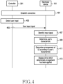
- FIG. 4 illustrates an example of a signal flow of an electronic device for optimizing a UI according to various embodiments.
- the electronic device 101 may be connected to the controller 301.
- the electronic device 101 may be connected to the controller 301 according to various schemes.
- the electronic device 101 may search for whether there is a connectable controller around the electronic device 101. If the electronic device 101 finds the connectable controller 301, the electronic device 101 may establish a connection to the controller 301.
- the electronic device 101 may receive an input for triggering a search for a controller, from a user (e.g., the user 300) based on execution of a particular application. In response to reception of the input, the electronic device 101 may search for the controller 301, and may establish a connection to the searched controller 301.
- An operation of establishing a connection to the controller 301 is not limited to the above-described example.
- the electronic device 101 may perform an operation of registering the controller 301 in the electronic device 101. This operation may be referred to as an "Out-Of-Box Experience (OOBE)".
- OOBE Out-Of-Box Experience
- the electronic device 101 may request the user to enter an input to the controller 301.
- the controller 301 may detect a user input.
- the electronic device 101 may display text and the like in a UI on the display of the electronic device 101, and thus may guide a user input.
- the electronic device 101 may display the text "Please press a trigger button on your shoulder.” in a UI, and thus may guide a user input.
- the term "trigger button” may refer to one physical button included in the controller 301.
- the electronic device 101 may display a reference point in a UI, may display the text "Please point at the reference point, and then press a trigger button.”, and thus may guide a user input.
- the electronic device 101 may display the text "Please hold the controller in your left hand, and then turn your left wrist by one revolution.”, and thus may guide a user input.
- the controller 301 may detect a user input according to guidance displayed in a UI of the electronic device 101.
- a user input may include a click on the controller 301, a double click thereon, a long press thereon, a drag thereon, shaking thereof, or the like.
- Examples of the user input may include various types of inputs related to the controller 301, but the disclosure is not limited to the above-described examples.
- the controller 301 may transmit a signal representing a user input (hereinafter, "user input signal") to the electronic device 101.
- the controller 301 may transmit a user input signal to the electronic device 101 in response to detection of the user input.
- the controller 301 may transmit a user input signal to the electronic device 101 in response to detection of a user input.
- the user input may include an input via a physical button (e.g., a trigger button) or a touch pad included in the controller 301.
- Information on an input may be identified by at least one sensor (e.g., an acceleration sensor, an angular velocity sensor, a gyro sensor, or a GPS sensor) included in the controller 301.
- the controller 301 may transmit various pieces of information related to a user input to the electronic device 101 via an input signal. For example, the controller 301 may transmit, to the electronic device 101, information on a position at which a user input is received, a movement distance of the controller 301 until reception of the user input, and the like.
- the electronic device 101 may associate the information included in the input signal received from the controller 301 with a content being displayed in a UI, and thus may identify what the received signal represents. For example, the electronic device 101 may receive an input signal from the controller 301 while a UI including the text "Please press a trigger button on your shoulder.” is displayed. In this example, the electronic device 101 may identify that the received input signal is a signal representing a position of the user's shoulder.
- the electronic device 101 may identify information on a position or movement of the controller 301 included in the input signal of the controller 301. In some embodiments, the electronic device 101 may identify information on a position or movement of the controller 301 via a sensor included in the electronic device 101. The sensor included in the electronic device 101 may be, for example, a sensor capable of tracking movement of the controller 301. In some other embodiments, the electronic device 101 may identify an input signal based on mutual information exchange between a sensor included in the electronic device 101 and a sensor included in the controller 301.
- the process of operation 403 to operation 407 may be repeated.
- the electronic device 101 may display another UI including text requesting an input of a position to which the user's arm is extended, based on identifying of a signal representing a position of the user's shoulder.
- the controller 301 may detect a user input based on another displayed UI, and thus may transmit a signal representing the input to the electronic device 101.
- the electronic device 101 may identify the received signal, and thus may determine a position to which the user's arm is extended.
- the electronic device 101 determines the user's characteristic.
- the electronic device 101 determines the user's characteristic based on identifying of the input signal.
- the user's characteristic includes the user's physical characteristic.
- the user's characteristic includes the user's height and may include the user's arm span, a movable range of the user's wrist, or a distance in a case where the user's arm can be maximally extended.
- Information on the user is not limited to the above-described example, and may include various pieces of information on the user related to use of the electronic device 101.
- the electronic device 101 may determine a user's characteristic based on a database.
- the database may be stored in the form of Table 1 below.
- Table 1 Shoulder position Position to which arm is extended User's characteristic (user's height) (0,0) (70,0) 130 cm (80,0) 145 cm (90,0) 160 cm (100,0) 175 cm (110,0) 190 cm (10, 0) (70,0) 120 cm (80,0) 135 cm (90,0) 150 cm (100,0) 165 cm (110, 0) 180 cm
- the electronic device 101 may determine a user's characteristic based on a mathematical formula.
- Information on a mathematical formula may be pre-stored in the electronic device 101.
- the electronic device 101 may determine a user's characteristic based on information on a mathematical formula included in Table 1 below and information on an input signal.
- the electronic device 101 may designate a particular value (e.g., 15 cm) for H, that is, the user's hand size, in each of the mathematical formulas (mathematical formula 1 to mathematical formula 4) in Table 1.
- the electronic device 101 may determine the user's height by using the mathematical formulas based on identifying of the user's arm span.
- a mathematical formula for calculation of a user's height is described, but without being limited thereto, various mathematical formulas or algorithms for determination of a user's characteristic may be used.
- the electronic device 101 may determine an arrangement (or a configuration) of a UI corresponding to the user's characteristic. Information on the arrangement of a UI may be mapped to the user's characteristic so as to be stored in the electronic device 101. The electronic device 101 may determine an arrangement of a UI based on identifying of the stored information.
- the electronic device 101 may include at least one UI arrangement mode having different arrangement forms.
- the UI arrangement modes may be mapped to respective characteristics of users.
- the electronic device 101 may determine a UI arrangement mode mapped to the user's characteristic determined in operation 409. For example, when the user's height is less than or equal to 150 cm, the electronic device 101 may determine that a UI arrangement mode is a first mode. When the user's height exceeds 150 cm and is less than or equal to 180 cm, the electronic device 101 may determine that a UI arrangement mode is a second mode. When the user's height exceeds 180 cm, the electronic device 101 may determine that a UI arrangement mode is a third mode.
- information on arrangement of a UI may include, for example, information on a range in which a UI is displayed on a display, information on arrangement of at least one object included in a UI, or information on the size of at least one object included in a UI.
- the electronic device 101 may display a UI to which the determined arrangement has been applied.
- the electronic device 101 may store information on the determined arrangement in an OOBE mode, and thus may determine a basic arrangement of a UI of the electronic device 101.
- the electronic device 101 may display a UI based on the determined arrangement.
- the electronic device 101 may adjust display (or FOV) of a UI based on the determined arrangement.
- the electronic device 101 may display a UI so as to provide a FOV optimized for each user.
- the controller 301 may include multiple controllers.
- the controller 301 may include a left-hand controller and a right-hand controller.
- the user may press buttons included in the multiple controllers in a state in which the user holds the multiple controllers in both hands, respectively.
- each of the multiple controllers may transmit, to the electronic device 101, a signal representing an input via a physical button detected by each of the multiple controllers.
- the electronic device 101 may receive, from the controller 301, a signal representing an input.
- the electronic device 101 may receive a user input signal from each of the multiple controllers.
- the electronic device 101 may identify the received user input signal.
- the electronic device 101 may identify information represented by the received user input signal. For example, the electronic device 101 may identify whether the received user input signal is a signal representing a position of the user's shoulder or a signal representing a position to which the user's arm is extended. This identification may be performed based on at least one sensor (e.g., an acceleration sensor, an angular velocity sensor, a gyro sensor, or a GPS sensor) included in the electronic device 101 or the controller 301.
- a sensor e.g., an acceleration sensor, an angular velocity sensor, a gyro sensor, or a GPS sensor
- the electronic device 101 may identify each of the multiple user input signals, and thus may identify information represented by each of the multiple user input signals. For example, the electronic device 101 may receive multiple signals representing positions, to which both arms are extended, via the multiple controllers. The electronic device 101 may identify the multiple signals, and thus may identify the multiple signals representing a position to which the left arm is extended and a position to which the right arm is extended.
- operation 501 and operation 503 may be repeated. In some embodiments, operation 501 and operation 503 may be repeated based on display of a UI. For example, when a UI related to a position of the user's shoulder is initially displayed, operation 501 and operation 503 may be performed. Then, when a UI related to a position, to which the user's arm is extended, is displayed, operation 501 and operation 503 may be repeated again.
- the electronic device 101 may determine an anchor point according to the user's characteristic.
- the electronic device 101 may determine an anchor point of the controller 301 or an anchor point for display of a UI of the electronic device 101, according to the user's characteristic.
- An anchor point may include a central axis for display of a UI.
- the electronic device 101 may determine a reference point for display of a UI, based on the anchor point.
- the electronic device 101 may display or adjust a UI with reference to the determined reference point. In some embodiments, when there is a predesignated anchor point, the electronic device 101 may adjust (or change) a position of the anchor point according to the determined user's height.
- the electronic device 101 may configure a reference position of an anchor point, according to the determined user's height.
- the electronic device 101 may arrange the UI or objects included in the UI with reference to the anchor point.
- the electronic device 101 may move the anchor point in the z-axis direction, and thus may adjust the UI (or display of the UI).
- an anchor point may be changed based on the user's height.
- the electronic device 101 may change an anchor point in a direction further away from or nearer to a UI on the z-axis.
- the electronic device 101 may include a default height. When the user's height is greater than the default height, the electronic device 101 may adjust (or change) a position of an anchor point so that the anchor point can be further away from a UI. In some other embodiments, when the user's height is less than the default height, the electronic device 101 may adjust an anchor point in a direction nearer to a UI.
- an adjustment distance of an anchor point may be determined according to a ratio of a default height to a user's height. For example, when a default height is 1 m and a reference anchor point has a position of 1 on the z-axis, in response to a user's height of 1.8 m, the electronic device 101 may adjust a position of an anchor point so that the anchor point can have a position of 1.8.
- a direction further away from a UI may be configured as a positive direction (a plus direction) on the z-axis.
- the electronic device 101 may pre-store anchor point values corresponding to respective heights in a database.
- the electronic device 101 may determine an anchor point based on determination of a user's height.
- the electronic device 101 may use various schemes to determine an anchor point, and the disclosure is not limited to the above-described example.
- the electronic device 101 may display a UI.
- the electronic device 101 may adjust (or adjust and display) the UI with reference to the determined anchor point. For example, when an anchor point of a UI is changed, the electronic device 101 may change (or change and display) an arrangement of a UI with reference to the changed anchor point.
- the electronic device 101 may change the arrangement of the UI, and thus may adjust display (or FOV) of the UI according to the user's height.
- the electronic device 101 may adjust a UI for each user, and thus may provide a UI optimized for a user.
- the electronic device 101 may efficiently control a UI based on the anchor point.
- the electronic device 101 may change an anchor point, configured to display an object representing an input via the controller 301, on a UI of the electronic device 101.
- the electronic device 101 may change the anchor point, and thus may configure, for each user, manipulation of an input via the controller 301.
- FIG. 6 illustrates an example of a UI configured to determine a user's characteristic according to various embodiments.
- FIG. 6 illustrates an example in which there is one controller 301 connected to the electronic device 101.
- a UI 601 may be an initial execution screen (or an OOBE screen or a configured screen) of the electronic device 101. At the time of initial execution, the electronic device 101 may display the UI 601, and thus may configure initial values. The electronic device 101 may display the UI 601 in a state of being connected to the controller 301. The electronic device 101 may detect an input of a height measurement item included in a UI via the controller 301.
- the UI 601 may be displayed for initial configuration.
- the electronic device 101 may display the UI 701, and thus may configure pieces of initial information (e.g., input of a user account, configuration of a user background, configuration of brightness of a UI, and configuration of a user environment) for operation of the electronic device 101.
- the UI 601 may be displayed based on initiation of an application (e.g., a configuration application) for configuration of the electronic device 101.
- the UI 601 may be displayed in response to boot-up of the electronic device 101.
- the electronic device 101 displays a UI 603 based on detection of an input of a height measurement item.
- the UI 603 guides manipulation of the controller 301 by the user.
- the UI 603 may include the text "Please put the controller against your shoulder and press a trigger button.”
- the controller 301 may detect a user input via a trigger button in a state of being held by the user.
- the electronic device 101 receives at least one of information on a user input of pressing the trigger button or a sensor value related to a user input, from the controller 301 while displaying the UI 603 (or after displaying the UI 603).
- the electronic device 101 may identify a position of the user's shoulder based on the at least one of the information on the user input or the sensor value related to the user input.
- the electronic device 101 displays a UI 605 in response to reception of the user input.
- the UI 605 is then used to guide a subsequent action required to determine the user's characteristic (e.g., the user's physical characteristic).
- the subsequent action may include, for example, the user's action of pressing a physical button of the controller 301 at the position of the user's shoulder, or the user's action of pressing a physical button of the controller 301 in a state in which the user's arm is extended.
- the UI 605 may include the text "Please maximally extend your arm forwards, and then press a trigger button.”
- the user may perform an action of pressing a button (e.g., a trigger button) included in the controller 301 in a state in which the user holds the controller in the user's hand and extends the user's arm.
- a button e.g., a trigger button
- the electronic device 101 may receive a user input of pressing a trigger button from the controller 301 while displaying the UI 605 (or after displaying the UI 605).
- the electronic device 101 may identify a position to which the user's arm is extended, based on reception of the user input.
- the UI 603 or the UI 605 may be displayed regardless of the order thereof. For example, after the UI 605 is displayed, the UI 603 may be displayed based on reception of an input related to the UI 605.
- the electronic device 101 may determine the user's arm span based on a position of the user's shoulder and a position to which the user's arm is extended. For example, the electronic device 101 may identify a distance between a position of the user's shoulder and a position to which the user's arm is extended, and thus may determine the user's arm span. The electronic device 101 may determine the user's height by using the determined user's arm span. In order to determine the user's height, the electronic device 101 may use a mathematical formula (e.g., mathematical formula 1 to mathematical formula 4 included in Table 1) or may use pre-stored information. Various schemes may be used to determine the user's height, and the disclosure is not limited to the above-described example.
- a mathematical formula e.g., mathematical formula 1 to mathematical formula 4 included in Table 1
- the electronic device 101 may store information on the user's height as information for display of a UI, based on determination of the user's height.
- the electronic device 101 may determine a form of display of a UI of the electronic device 101, an arrangement of a UI, or an object included in a UI, based on the information on the user's height.
- the electronic device 101 may adjust an anchor point based on the information on the user's height.
- the electronic device 101 may apply the adjusted anchor point, and thus may change display of a UI so as to be optimized for the user.
- the electronic device 101 may display a UI 607 based on storage of the information on the user's height.
- the UI 607 may include text representing the information on the user's height.
- the UI 607 may include the text "130 cm is input as an estimated height.”
- a height measurement operation according to the first configuration of the electronic device 101 may be terminated based on display of the UI 607.
- the electronic device 101 may terminate the first configuration for display of a UI.
- the electronic device 101 may display the UI 601 based on reception of a user input for configuration, and in this example, the operations of FIG. 6 may be performed repeatedly.
- the UI 603 to the UI 607 may include various texts for guiding the actions of measuring the user's height, and the disclosure is not limited to the above-described example.
- FIG. 7 illustrates an example of a UI configured to determine a user's characteristic not falling within the scope of the claims.
- FIG. 7 illustrates an example in which there are multiple controllers (e.g., two controllers) connected to the electronic device 101. The multiple controllers may all have the same configuration.
- a UI 701 is illustrated as an example of an initial configuration screen (or an OOBE screen) of the electronic device 101.
- the electronic device 101 may display the UI 701, and thus may configure pieces of initial information (e.g., input of a user account, configuration of a user background, configuration of brightness of a UI, and configuration of a user environment) for operation of the electronic device 101.
- the electronic device 101 may display the UI 701 in a state of being connected to the multiple controllers.
- the electronic device 101 may detect an input of a height measurement item included in a UI via at least one of the multiple controllers.
- the electronic device 101 may display a UI 703 based on detection of an input of a height measurement item.
- the UI 703 may include the text "Please hold the controllers in your both hands and extend your both arms, and then press respective trigger buttons.”
- the user may extend both arms, and may then perform an action of pressing buttons (e.g., trigger buttons) included in the respective controllers which are being held in the user's both hands.
- Each of the multiple controllers may transmit a signal representing a user input (e.g., an input signal) to the electronic device 101 in response to reception of the user input.
- the electronic device 101 may determine lengths of the both arms based on the received input signals.
- the electronic device 101 may identify a position to which the left hand is extended and a position to which the right hand is extended, via the multiple controllers.
- the electronic device 101 may identify a distance between the left hand and the right hand, and thus may determine lengths of the both arms.
- the electronic device 101 may use mathematical formulas (e.g., mathematical formula 1 to mathematical formula 4 included in Table 1) or may use pre-stored information.
- mathematical formulas e.g., mathematical formula 1 to mathematical formula 4 included in Table 1
- Various schemes may be used to determine the user's height, and the disclosure is not limited to the above-described example.
- the electronic device 101 may store information on the determined user's height.
- the electronic device 101 may display a UI 705 based on storage of the information on the user's height.
- the UI 705 may include text representing the information on the user's height.
- the UI 705 may include the text "130 cm is input as an estimated height.”
- a height measurement operation according to the first configuration of the electronic device 101 may be terminated based on display of the UI 705.
- the electronic device 101 may terminate the first configuration for display of a UI.
- the electronic device 101 may display the UI 705 based on reception of a user input for configuration, and in this example, the operations of FIG. 7 may be performed repeatedly.
- the UI 703 to the UI 705 may include various texts for guiding the actions of measuring the user's height, and the disclosure is not limited to the above-described example.
- FIG. 8 illustrates an example of configuration of an anchor point for optimization of a UI according to various embodiments.
- the electronic device 101 may be connected to the multiple controllers 301.
- the electronic device 101 may adjust anchor points 801 and 803 for displaying objects representing inputs via the controllers 301 on a UI.
- an anchor point of the electronic device 101 may have a default value.
- the anchor point may have a default value according to, for example, a default height or a reference-arm span.
- the default value may include a value of a position of an anchor point.
- the electronic device 101 may adjust an anchor point based on identifying of a user's characteristic (e.g., the user's height or the user's arm span).
- the adjusted anchor point may be an anchor point optimized (or adaptively determined) based on the user's characteristic.
- a UI 805 is illustrated as an example of a UI displayed based on a predesignated anchor point 801.
- the anchor point 801 may be determined to correspond to designation of a as the user's reference-arm span.
- the electronic device 101 may adjust the anchor point 801.
- a UI 807 is illustrated as an example of a UI displayed based on the adjusted anchor point 803.
- the UI 807 may include a UI displayed based on adjustment of the anchor point 801.
- An adjustment range of the controllers 301 may be changed based on the adjustment of the anchor point 801. For example, even when an adjustment angle before a change in an anchor point is identical to an adjustment angle after the change in the anchor point, an object pointed at by each of the controllers may be changed.
- an anchor point may be adjusted according to the user's arm span a or b, and thus the electronic device 101 may optimize the controllers 301 for each user. Optimization makes it possible to enhance the usability with which a user can use the electronic device 101 or the controllers 301.
- FIG. 9 illustrates another example of an operation of an electronic device for optimizing a UI according to various embodiments.
- the electronic device 101 may receive, from the controller 301, an input signal representing an input of a reference point displayed by the electronic device 101.
- the electronic device 101 may display one or more reference points in the electronic device 101.
- the one or more reference points may be, for example, vertices included in any rectangular area in a 3D environment.
- the one or more reference points may be multiple reference points representing any circle in a 3D environment.
- the electronic device 101 may detect a user input of one or more reference points displayed via the controller 301.
- the electronic device 101 may receive an input signal of the controller via which the user points (or clicks on) one or more reference points.
- the electronic device 101 may measure or acquire data on a user action (or a user movement) of pointing at one or more reference points by using the controller 301.
- the electronic device 101 may measure or acquire data on a user action (or a user movement) via at least one sensor included in the controller 301 or the electronic device 101.
- the electronic device 101 may acquire information on a position of the controller in the case of pointing at a reference point.
- the electronic device 101 may identify the received input signal, and thus may determine a user input range.
- the user input range may be determined based on the user's characteristic (e.g., the user's physical characteristic).
- the user input range may represent a range in which the user can make an input.
- the user input range may be a range in which the user's arm can be extended.
- the electronic device 101 may identify an area in which the controller can move, and thus may determine a user input range.
- the user input range may include a range in which a user input can be detected by the controller 301.
- the electronic device 101 may determine an arrangement of a UI, according to the determined user input range. In some embodiments, the electronic device 101 may determine an arrangement of a UI so as to display the UI in the determined user input range. In some other embodiments, the electronic device 101 may determine an arrangement of an object included in a UI so as to display the object in the determined user input range.
- the object may be configured to receive an input.
- an object may be executed based on reception of an input.
- the object may be an icon representing a designated application. The designated application may be executed based on reception of an input of the object.
- objects may include various types of contents, such as images, icons, text, and video. In still some other embodiments, an object may refer to a window including various types of contents.
- the electronic device 101 may display a UI.
- the electronic device 101 may display a UI based on the determined arrangement of the UI or the determined arrangement of the object.
- the displayed UI may be a UI optimized for each user.
- the electronic device 101 can provide a UI of which the convenience, easiness, or usability for a user is enhanced.
- FIG. 10 illustrates another example of a UI configured to determine a user's characteristic according to various embodiments.
- the electronic device 101 is illustrated as an example of a UI configured to determine a user input range.
- a UI 1001 is illustrated as an example of an initial configuration screen (or an OOBE screen) of the electronic device 101.
- the UI 1001 may be configured by further including, in the UI 701, an item (or a menu) for measurement of an input range.
- the electronic device 101 may display a UI 1003 based on detection of an input of an item for measurement of an input range via the controller 301.
- the UI 1003 may include text for displaying start of an action of measuring an input range.
- the UI 1003 may include the text "An input area of the controller is directly configured.”
- the electronic device 101 may display a UI 1005 or a UI 1007.
- the UI 1005 may include a UI configured to guide a user input for determination of an input range related to the user's right arm.
- the UI 1005 may include, for example, the text "Please hold a controller in your right hand, and press a trigger button while pointing at each point displayed on a screen.”
- the user may press a trigger button of the controller 301 whenever pointing at each point included in the UI 1005, and thus the controller 301 may transmit an input signal representing a user input to the electronic device 101.
- the UI 1007 may include a UI configured to guide a user input for determination of an input range related to the user's left arm.
- the UI 1007 may include, for example, the text "Please hold a controller in your right hand, and press a trigger button while pointing at each point displayed on a screen.”
- the electronic device 101 may include at least one sensor, and may identify a movement range, a movement distance, or movement of the controller 301 via the at least one sensor.
- the electronic device 101 may determine a user input range represented by a user input signal based on identifying of the same.
- the user input range may be an area including maximum distances related to positions that the user's hands can reach.
- multiple controllers may be connected to the electronic device 101.
- the electronic device 101 may receive an input via a controller designated for the user's right hand.
- the electronic device 101 may receive an input via a controller designated for the user's left hand.
- the UI 1005 and the UI 1007 may be displayed regardless of the order thereof.
- Each of the UI 1003, the UI 1005, and the UI 1007 may include various texts for guiding the actions of measuring a user input range, and the disclosure is not limited to the above-described example.
- FIG. 11 illustrates an example of a UI optimized according to various embodiments.
- a UI 1101 may include a UI displayed based on a default UI configuration.
- the UI 1103 may include a UI optimized for a user by an electronic device according to various embodiments.
- the electronic device 101 may include a default configuration for display of a UI.
- the electronic device 101 may display a UI based on the default configuration.
- an object may be displayed at a fixedly-designated position of the electronic device 101.
- the electronic device 101 may change display of a UI via an optimization process.
- the changed UI may correspond to the UI 1103, and a position of an object having been displayed on the UI 1101 may be changed.
- a UI may be changed based on the user's characteristic.
- the electronic device 101 may arrange an object at a position further away on a central axis.
- the electronic device 101 may arrange an object at a position nearer on the central axis.
- the height of the user who uses the UI 1103 may be less than the default height.
- an object may be arranged at a position nearer on the central axis than in the case of the UI 1101.
- the adjusted area may be optimized for the user's characteristic (e.g., an arm span or a height).
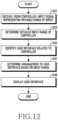
- FIG. 12 illustrates an example of an operation of an electronic device for optimizing a UI related to a controller according to various embodiments.
- the electronic device 101 may receive, from the controller 301, an input signal representing a movable range of a wrist.
- the movable range of the wrist may include a range in which the wrist can move in a state in which a position of an arm is fixed.
- the electronic device 101 may identify movement of the controller 301 based on at least one sensor (e.g., an angular velocity sensor or an acceleration sensor) included in the controller 301.
- the electronic device 101 may determine a detailed input range of the controller 301.
- the detailed input range of the controller 301 may include a range in which a wrist of a user of the electronic device 101 can move.
- the electronic device 101 may determine a detailed input range of the controller 301 based on identifying of the movement of the controller 301.
- the electronic device 101 may determine an arrangement of a UI related to the controller 301 based on the detailed input range determined in operation 1203. In order to display a UI related to the controller 301 in the detailed input range, the electronic device 101 may determine an arrangement of the UI related to the controller 301.
- the UI related to the controller 301 may include, for example, a content, a menu, or the like related to the controller 301.
- the content or the menu related to the controller 301 may be an object configured to detect an input based on rotation of the controller 301.
- the electronic device 101 may change an arrangement of the UI related to the controller 301 so that the UI related to the controller 301 can be included in the determined detailed input range. For example, the electronic device 101 may determine that an interval between icons displayed to be spaced apart from each other at intervals of 10 cm is changed to 5 cm in a UI related to the controller 301 so that the UI can be displayed in the detailed input range.
- the electronic device 101 may display a UI based on the determined arrangement of the UI related to the controller 301.
- the electronic device 101 may display the UI related to the controller 301, based on the determination made in operation 1205.
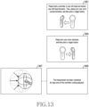
- FIG. 13 illustrates an example of a UI configured to determine a user's characteristic related to a controller according to various embodiments.
- the UI 1301 may include a UI displayed in order to determine a detailed input area of the controller 301.
- the UI 1301 may be a UI displayed in order to determine a detailed input area of the controller 301 related to a counterclockwise rotation of a left hand.
- the UI 1301 may include the text for guiding a user action, reading "Please hold a controller in your left hand and extend your left hand forwards. Then, please turn your wrist counterclockwise, and then press a trigger button.”
- the electronic device 101 may display a UI 1303.
- the UI 1303 may include a UI displayed in order to determine a detailed input area of the controller 301.
- the UI 1303 may be a UI displayed in order to determine a detailed input area of the controller 301 related to a clockwise rotation of the left hand.
- the UI 1303 may include the text for guiding a user action, reading "Please turn your wrist clockwise, and then press a trigger button.”
- the electronic device 101 may be connected to multiple controllers. When the electronic device 101 is connected to two controllers, the electronic device 101 may further display a UI configured to determine a detailed input range of a controller for a right hand.
- the electronic device 101 may display a UI 1305 based on reception of a user input of a detailed input range of the controller 301.
- the UI 1305 may include a UI configured to guide completion of measurement for determination of a detailed input range.
- the UI 1305 may include the text "The measurement is completed. An input area of the controller is being adjusted.”
- the electronic device 101 may adjust a detailed input range related to the controller 301, to an area 1311 from an area 1309.
- the electronic device 101 may adjust the detailed input range by identifying movement of the controller 301 with reference to a rotation axis of yaw, pitch, or roll of the controller 301.
- a rotation axis of yaw may be the z-axis (or an axis in a gravity direction)
- a rotation axis of pitch may be the y-axis
- a rotation axis of roll may be the x-axis.
- the area 1311 may correspond to the detailed input range determined in the above-described operations.
- the area 1311 may correspond to the input range optimized based on the movable range of the user's wrist.
- the electronic device 101 may measure an input range of the controller 301, and thus may identify an error range of an input via the controller 301.
- the area 1311 of the controller 301 may correspond to an error range of an input via the controller 301 relative to a UI of the electronic device 101.
- the UI 1301, the UI 1303, and the UI 1305 include various texts for guiding the actions of measuring a movable range of the user's wrist, and the disclosure is not limited to the above-described example.
- FIG. 14 illustrates an example of a UI which is optimized in relation to a controller according to various embodiments.
- the electronic device 101 may display a UI 1401 related to the controller 301.
- the UI 1401 may display one or more icons based on movement of the controller 301. Around the one or more icons, a description or the name of each icon may be displayed. One icon 1405 selected from the one or more icons may be emphasized and displayed so that the selection of the same can be represented. In order to emphasize the icon 1405, various methods for displaying the icon 1405 differently from display of the remaining icons may be used, and the disclosure is not limited to the illustrated example.
- various schemes may be used for an input for selecting one icon from one or more icons via the controller 301.
- the controller 301 may select an icon for a rotational motion which is based on a rotation axis of yaw, pitch, or roll.
- the electronic device 101 may select one icon based on detection of a user input via a touch pad included in the controller 301.
- the electronic device 101 may change the UI 1401 to a UI 1403 and display the UI 1403, based on detection of a detailed input range of the controller 301.
- the UI 1403 may be a UI adjusted (or rearranged) to display one or more icons in the detailed input range.
- the electronic device 101 may adjust sizes of one or more icons based on detection of a detailed input range of the controller 301, and thus may perform adjustment so as to display the one or more icons in the detailed input range. For example, the electronic device 101 may reduce sizes of one or more icons, and thus may adjust an area for display of the one or more icons.
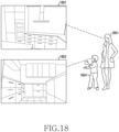
- FIG. 15 illustrates an example of a UI displayed according to various embodiments.
- a UI described below may include a UI related to a VR environment.
- the electronic device 101 may display a UI 1501.
- the UI 1501 may include one or more objects which are fixedly displayed at a designated position.
- forms in which the same UI 1501 is viewed may change according to respective characteristics of users.
- a short user 1503 e.g., a child
- a tall user 1505 e.g., an adult
- the user 1503 may recognize the UI, which the user views, as a UI 1601 of FIG. 16
- the user 1505 may recognize the same as a UI 1605 of FIG. 16 .
- FIG. 16 illustrates an example of a UI displayed in such a manner as to be optimized for a user according to various embodiments.
- Each of UIs described below may include a UI related to a VR environment.
- a UI 1601 and a UI 1603 may include a UI that a short user views.
- the electronic device 101 may adjust display (or FOV) of the UI 1601 based on a characteristic of the short user (e.g., a height, an input range, or a movable range of a wrist).
- the electronic device 101 may display the UI 1603 based on adjustment of positions at which objects of the UI 1601 are displayed. For example, the electronic device 101 may perform adjustment such that positions, at which objects of the UI 1601 are displayed, are moved downwards by a particular distance and the objects are displayed at the moved positions. Through this configuration, the user of the electronic device 101 may recognize the UI in the form of viewing the UI straight ahead.
- the UI 1603 may have a form of a UI, which the user views straight ahead, based on the adjustment.
- a UI 1605 and a UI 1607 may include a UI that a tall user views.
- the electronic device 101 may adjust display (or FOV) of the UI 1605 based on a characteristic of the tall user (e.g., a height, an input range, or a movable range of a wrist) .
- the electronic device 101 may display the UI 1607 based on adjustment of positions at which objects of the UI 1605 are displayed. For example, the electronic device 101 may perform adjustment such that positions, at which objects of the UI 1605 are displayed, are moved upwards by a particular distance and the objects are displayed at the moved positions. Through this configuration, the user of the electronic device 101 may recognize the UI in the form of viewing the UI straight ahead.
- the UI 1607 may have a form of a UI, which the user views straight ahead, based on the adjustment.
- FIG. 17 illustrates another example of a UI displayed in such a manner as to be optimized for a user according to various embodiments.
- the electronic device 101 may adjust a UI 1701, displayed at a distant position, so that the UI 1701 can be displayed at a close-range position, based on a user's characteristic.
- the electronic device 101 may adjust an arrangement of the UI 1701 or an arrangement of objects included in the UI 1701, and thus may display a UI 1703.
- Objects of the UI 1703 may be displayed to have larger sizes than those of the UI 1701.
- FIG. 17 may illustrate a UI in a VR environment.
- FIG. 17 may illustrate an example related to one of a user's two eyes.
- the electronic device 101 may further display a UI which corresponds to the UI 1701 and is related to a view position (or a view direction) of the other eye of the user.
- the electronic device 101 may display a UI related to a view position of the left eye and a UI related to a view position of the right eye.
- the electronic device 101 may provide, via an application for providing VR, a UI related to each of a view position of the left eye and a view position of the right eye.
- the electronic device 101 may include a screen of another application (e.g., a photograph application or a game application) in a 3D screen so as to be rendered, by using an application for providing VR.
- FIG. 18 illustrates still another example of a UI displayed according to various embodiments.
- the electronic device 101 may include an application which needs provision of various FOVs in relation to a particular space.
- the electronic device 101 may include an interior application for representing how an interior design has been applied to a house.
- the electronic device 101 may include a shopping application.
- the electronic device 101 may provide, via the shopping application, a UI obtained by applying furniture, desired to be purchased by a user, to a structure or interior of the user's house. Since it is possible to provide the user with information based on FOVs different according to users' heights, the electronic device 101 may provide a UI (or FOV) corresponding to the user's height.
- the electronic device 101 may identify whether an executed application is an application which requires FOVs different according to users. If the executed application requires FOVs different according to users, the electronic device 101 may identify the predetermined user's characteristic (e.g., the user's height or the user's arm span) or may perform at least one operation (e.g., the operations of FIG. 4 ) of determining the user's characteristic. The electronic device 101 may adjust display of a UI based on the user's characteristic. For example, when the user is a tall user 1801, the electronic device 101 may provide the user with a UI (or FOV) 1801 in the form of looking down from above.
- a UI or FOV
- the electronic device 101 may provide the user with a UI (or FOV) 1803 in the form of looking up from below.
- UI or FOV
- the UIs described above with reference to FIG. 18 may be UIs which can be displayed in a VR environment.
- FIG. 19 illustrates an example of an object displayed based on a user's characteristic according to various embodiments.
- the electronic device 101 may generate a character representing a user based on execution of a character application (or an avatar application).
- the electronic device 101 may pre-store information on a basic character 1901.
- the electronic device 101 may identify the user's characteristic based on execution of the character application.
- the electronic device 101 may identify the user's characteristic based on the stored information.
- the electronic device 101 may perform at least one operation (e.g., the operations of FIG. 4 ) of determining the user's characteristic based on execution of a character application.
- the electronic device 101 may change a size and the like of the basic character 1901 based on the user's characteristic. For example, the electronic device 101 may compare information on a height of the basic character 1901 with information on the user's height, and thus may generate a character 1903 reflecting the user's characteristic. As another example, the electronic device 101 may compare information on the height of the basic character 1901 with information on the user's height, and thus may change the basic character 1901 to the character 1903 reflecting the user's characteristic.
- the characters described above with reference to FIG. 19 may be VR objects (or 3D objects) which can be displayed in a VR environment.
- the characters are illustrated as an example in FIG. 19 , but various contents, objects, icons, or the like may also be rearranged, reconfigured, or readjusted based on the user's characteristic.
- the electronic device 101 may store the user's information in an application for health care (e.g., a health application) based on the user's characteristic.
- the electronic device 101 may measure information on a numerical value affected by the height based on the stored information.
- the numerical value affected by the height may be calories consumed by the user or a standard weight.
- the electronic device 101 may determine the user's stride based on information on the user's height.
- the electronic device 101 may determine calories, consumed by the user, based on the determined user's stride. Calories consumed by the user may be determined based on the user's stride and the user's step count.
- the electronic device 101 may determine a standard weight based on information on the user's height. For example, the electronic device 101 may determine that a standard weight is a value obtained by multiplying a value, obtained by subtracting 100 from the height, by 0.9.
- a computer-readable storage medium for storing one or more programs (software modules) may be provided.
- the one or more programs stored in the computer-readable storage medium may be configured for execution by one or more processors within the electronic device.
- the at least one program may include instructions that cause the electronic device to perform the methods according to various embodiments of the disclosure as defined by the appended claims and/or disclosed herein.
- the programs may be stored in non-volatile memories including a random access memory and a flash memory, a read only memory (ROM), an electrically erasable programmable read only memory (EEPROM), a magnetic disc storage device, a compact disc-ROM (CD-ROM), digital versatile discs (DVDs), or other type optical storage devices, or a magnetic cassette.
- ROM read only memory
- EEPROM electrically erasable programmable read only memory
- CD-ROM compact disc-ROM
- DVDs digital versatile discs
- any combination of some or all of them may form a memory in which the program is stored.
- a plurality of such memories may be included in the electronic device.
- the programs may be stored in an attachable storage device which may access the electronic device through communication networks such as the Internet, Intranet, Local Area Network (LAN), Wide LAN (WLAN), and Storage Area Network (SAN) or a combination thereof.
- a storage device may access the electronic device via an external port.
- a separate storage device on the communication network may access a portable electronic device.
- an element included in the disclosure is expressed in the singular or the plural according to presented detailed embodiments.
- the singular form or plural form is selected appropriately to the presented situation for the convenience of description, and the disclosure is not limited by elements expressed in the singular or the plural. Therefore, either an element expressed in the plural may also include a single element or an element expressed in the singular may also include multiple elements.
Landscapes
- Engineering & Computer Science (AREA)
- General Engineering & Computer Science (AREA)
- Theoretical Computer Science (AREA)
- Physics & Mathematics (AREA)
- General Physics & Mathematics (AREA)
- Human Computer Interaction (AREA)
- Optics & Photonics (AREA)
- User Interface Of Digital Computer (AREA)
Description
- Various embodiments relate to an electronic device and a method for adaptively configuring a user interface based on a user's physical characteristic.
- With the progress of technology for electronic devices, an electronic device may provide various User Experiences (UXs). For example, the electronic device may provide a content for a virtual world, that is, Virtual Reality (VR), which is similar to the reality but is not real. The electronic device may provide VR, and thus may provide rich experience to a user.
US 2017/309079 describes a device that can display a visual aura representing contextual information associated with an object that is outside the user's field of view. The visual aura can be displayed near an edge of the field of view and can dynamically change as the contextual information associated with the object changes, e.g., the relative position of the object and the user (or the user's field of view) changes.
US 2017/228036 relates to a multimedia entertainment system that combines both gestures and voice commands to provide an enhanced control scheme. A user's body position or motion may be recognized as a gesture, and may be used to provide context to recognize user generated sounds, such as speech input.
US 2017/329419 relates to a system for combining a gyromouse input with a touch surface input in an augmented reality (AR) environment and/or a virtual reality (VR) environment, a virtual display of virtual items and/or features may be adjusted in response to movement of the gyromouse combined with touch inputs, or touch and drag inputs, received on a touch surface of the gyromouse.
US 2012/231853 relates to a movement function of a display screen of an information terminal such as a mobile device is controlled in response to a type of user operation to prevent erroneous selection of selectable items and improve operability.
US 2012/206452 describes a technology for providing realistic occlusion between a virtual object displayed by a head mounted, augmented reality display system and a real object visible to the user's eyes through the display.
US 2015/070274 describes techniques to allow for a wearable display device, such as a head-mounted display, to be tracked within a 3D space by dynamically generating 6DoF data associated with an orientation and location of the display device within the 3D space. The 6DoF data is generated dynamically, in real time, by combining of 3DoF location information and 3DoF orientation information within a user-centered coordinate system.
DE 20 2017 104403 relates to systems and methods to provide for a determination of whether a particular application is usable by a particular user based on the current physical location of the user. The systems and methods can provide the ability to make minor positional adjustments to improve user comfort, and can additionally provide larger positional adjustments to help make the application accessible to the user from the user's current physical position (e.g., standing , sitting, etc.).
US 2016/375364 describes methods, systems, and computer programs for obtaining profile data of a user from a wearable device. One example method includes connecting a peripheral device with a base computing device via a data connection.
US 2013/328927 describes a system for generating a virtual gaming environment based on features identified within a real-world environment, and adapting the virtual gaming environment over time as the features identified within the real-world environment change.
WO 2012/094143 relates to gesture recognition and in particular to a method of obtaining a physical dimension of a user and determining a gesture based on the determined physical dimension in order to improve accuracy of the gesture recognition. - A user who receives a content for VR may have a Field of View (FOV) which is different from another's due to physical characteristics of the users. The user, who views a content for VR by using an electronic device which displays a content for VR in a fixed configuration or arrangement, may be inconvenienced due to a difference of a FOV caused by the user's physical characteristic. Therefore, there may be a need for a method for providing a content for VR in a configuration adaptively changed according to the user's physical characteristic.
- Various embodiments may provide an electronic device and a method for displaying a content for VR in a
configuration adaptively changed based on information representing a user's physical characteristic. - The technical subjects pursued in the disclosure may not be limited to the above mentioned technical subjects, and other technical subjects which are not mentioned may be clearly understood, through the following descriptions, by those skilled in the art to which the disclosure pertains.
- In accordance with an aspect of the disclosure, an electronic device may include: a memory configured to store instructions; a communication interface; a display; and at least one processor configured to be connected to the communication interface and the memory, wherein the at least one processor is configured to execute the stored instructions to: display, on the display, a first UI which guides an action of a user of the electronic device such that an external electronic device grasped by the user is placed at a specific position on the user's body; receive a first signal, which is transmitted by the external electronic device and is used to determine the user's physical characteristic related to the electronic device and the external electronic device according to the first UI, display, on the display, a second UI which guides a subsequent action of the user such that the user's arm is extended; receive a second signal, which is transmitted by the external electronic device and is used to determine the user's physical characteristic related to the electronic device and the external electronic device, in response to detection of the user input in the external electronic device according to the second UI; and the at least one processor is further configured to execute the stored instructions to: identify a distance between a position at which the first signal is received and a position at which the second signal is received, the identified distance comprising an arm span associated with the user, determine the user's physical characteristic based on the identified distance, wherein the user's physical characteristic comprises a height of the user, determine a Field of View (FOV) for the user based on the determined user's physical characteristic; and display a content for Virtual Reality (VR) based on the determined FOV.
- In accordance with another aspect of the disclosure, a method of an electronic device may include: displaying, on the display, a first UI which guides an action of a user of the electronic device such that an external electronic device grasped by the user is placed at a specific position on the user's body; receiving a first signal, which is transmitted by the external electronic device and is used to determine the user's physical characteristic related to the electronic device and the external electronic device according to the first UI; displaying, on the display, a second UI which guides a subsequent action of the user such that the user's arm is extended; receiving a second signal, which is transmitted by the external electronic device and is used to determine the user's physical characteristic related to the electronic device and the external electronic device, in response to detection of the user input in the external electronic device according to the second UI; and the method further comprising: identifying a distance between a position at which the first signal is received and a position at which the second signal is received, the identified distance comprising an arm span associated with the user; determining the user's physical characteristic based on the identified distance, wherein the user's physical characteristic comprises a height of the user; determining a Field of View (FOV) for the user based on the determined user's physical characteristic; and displaying a content for Virtual Reality (VR) based on the determined FOV.
- In accordance with still another aspect of the disclosure, a non-transitory computer-readable storage medium may include: displaying, on the display, a first UI which guides an action of a user of the electronic device such that an external electronic device grasped by the user is placed at a specific position on the user's body; receiving a first signal, which is transmitted by the external electronic device and is used to determine the user's physical characteristic related to the electronic device and the external electronic device according to the first UI; displaying, on the display, a second UI which guides a subsequent action of the user such that the user's arm is extended; receiving a second signal, which is transmitted by the external electronic device and is used to determine the user's physical characteristic related to the electronic device and the external electronic device, in response to detection of the user input in the external electronic device according to the second UI; identifying a distance between a position at which the first signal is received and a position at which the second signal is received, the identified distance comprising an arm span associated with the user; determining the user's physical characteristic based on the identified distance, wherein the user's physical characteristic comprises a height of the user;determining a Field of View (FOV) for the user based on the determined user's physical characteristic; and displaying a content for Virtual Reality (VR) based on the determined FOV.
- According to an electronic device and an operating method thereof according to various embodiments, the electronic device identifies a user's characteristic based on at least one signal received from another electronic device, and thus can provide a user interface optimized for the user.
- Effects obtainable from the disclosure may not be limited to the above mentioned effects, and other effects which are not mentioned may be clearly understood, through the following descriptions, by those skilled in the art to which the disclosure pertains.
-
-
FIG. 1 is a block diagram of an electronic device in a network environment according to various embodiments. -
FIG. 2 is a block diagram of a display module according to various embodiments. -
FIG. 3 illustrates an example of use of an electronic device and a controller according to various embodiments. -
FIG. 4 illustrates an example of a signal flow of an electronic device for optimizing a User Interface (UI) according to various embodiments. -
FIG. 5 illustrates an example of an operation of an electronic device for optimizing a UI according to various embodiments. -
FIG. 6 illustrates an example of a UI configured to determine a user's characteristic according to various embodiments. -
FIG. 7 illustrates an example of a UI configured to determine a user's characteristic not falling within the scope of the claims. -
FIG. 8 illustrates an example of configuration of an anchor point for optimization of a UI according to various embodiments. -
FIG. 9 illustrates another example of an operation of an electronic device for optimizing a UI according to various embodiments. -
FIG. 10 illustrates another example of a UI configured to determine a user's characteristic according to various embodiments. -
FIG. 11 illustrates an example of a UI optimized according to various embodiments. -
FIG. 12 illustrates an example of an operation of an electronic device for optimizing a UI related to a controller according to various embodiments. -
FIG. 13 illustrates an example of a UI configured to determine a user's characteristic related to a controller according to various embodiments. -
FIG. 14 illustrates an example of a UI which is optimized in relation to a controller according to various embodiments. -
FIG. 15 illustrates an example of a UI displayed according to various embodiments. -
FIG. 16 illustrates an example of a UI displayed in such a manner as to be optimized for a user according to various embodiments. -
FIG. 17 illustrates another example of a UI displayed in such a manner as to be optimized for a user according to various embodiments. -
FIG. 18 illustrates still another example of a UI displayed according to various embodiments. -
FIG. 19 illustrates an example of an object displayed based on a user's characteristic according to various embodiments. -
Fig. 1 is a block diagram illustrating anelectronic device 101 in anetwork environment 100 according to various embodiments. Referring toFig. 1 , theelectronic device 101 in thenetwork environment 100 may communicate with anelectronic device 102 via a first network 198 (e.g., a short-range wireless communication network), or anelectronic device 104 or aserver 108 via a second network 199 (e.g., a long-range wireless communication network). According to an embodiment, theelectronic device 101 may communicate with theelectronic device 104 via theserver 108. According to an embodiment, theelectronic device 101 may include aprocessor 120,memory 130, aninput device 150, asound output device 155, adisplay device 160, anaudio module 170, asensor module 176, aninterface 177, ahaptic module 179, acamera module 180, apower management module 188, abattery 189, acommunication module 190, a subscriber identification module (SIM) 196, or anantenna module 197. In some embodiments, at least one (e.g., thedisplay device 160 or the camera module 180) of the components may be omitted from theelectronic device 101, or one or more other components may be added in theelectronic device 101. In some embodiments, some of the components may be implemented as single integrated circuitry. For example, the sensor module 176 (e.g., a fingerprint sensor, an iris sensor, or an illuminance sensor) may be implemented as embedded in the display device 160 (e.g., a display). - The
processor 120 may execute, for example, software (e.g., a program 140) to control at least one other component (e.g., a hardware or software component) of theelectronic device 101 coupled with theprocessor 120, and may perform various data processing or computation. According to one embodiment, as at least part of the data processing or computation, theprocessor 120 may load a command or data received from another component (e.g., thesensor module 176 or the communication module 190) involatile memory 132, process the command or the data stored in thevolatile memory 132, and store resulting data innon-volatile memory 134. According to an embodiment, theprocessor 120 may include a main processor 121 (e.g., a central processing unit (CPU) or an application processor (AP)), and an auxiliary processor 123 (e.g., a graphics processing unit (GPU), an image signal processor (ISP), a sensor hub processor, or a communication processor (CP)) that is operable independently from, or in conjunction with, themain processor 121. Additionally or alternatively, theauxiliary processor 123 may be adapted to consume less power than themain processor 121, or to be specific to a specified function. Theauxiliary processor 123 may be implemented as separate from, or as part of themain processor 121. - The
auxiliary processor 123 may control at least some of functions or states related to at least one component (e.g., thedisplay device 160, thesensor module 176, or the communication module 190) among the components of theelectronic device 101, instead of themain processor 121 while themain processor 121 is in an inactive (e.g., sleep) state, or together with themain processor 121 while themain processor 121 is in an active state (e.g., executing an application). According to an embodiment, the auxiliary processor 123 (e.g., an image signal processor or a communication processor) may be implemented as part of another component (e.g., thecamera module 180 or the communication module 190) functionally related to theauxiliary processor 123. Thememory 130 may store various data used by at least one component (e.g., theprocessor 120 or the sensor module 176) of theelectronic device 101. The various data may include, for example, software (e.g., the program 140) and input data or output data for a command related thererto. Thememory 130 may include thevolatile memory 132 or thenon-volatile memory 134. - The
program 140 may be stored in thememory 130 as software, and may include, for example, an operating system (OS) 142,middleware 144, or anapplication 146. - The
input device 150 may receive a command or data to be used by other component (e.g., the processor 120) of theelectronic device 101, from the outside (e.g., a user) of theelectronic device 101. Theinput device 150 may include, for example, a microphone, a mouse, or a keyboard. - The
sound output device 155 may output sound signals to the outside of theelectronic device 101. Thesound output device 155 may include, for example, a speaker or a receiver. The speaker may be used for general purposes, such as playing multimedia or playing record, and the receiver may be used for an incoming calls. According to an embodiment, the receiver may be implemented as separate from, or as part of the speaker. - The
display device 160 may visually provide information to the outside (e.g., a user) of theelectronic device 101. Thedisplay device 160 may include, for example, a display, a hologram device, or a projector and control circuitry to control a corresponding one of the display, hologram device, and projector. According to an embodiment, thedisplay device 160 may include touch circuitry adapted to detect a touch, or sensor circuitry (e.g., a pressure sensor) adapted to measure the intensity of force incurred by the touch. - The
audio module 170 may convert a sound into an electrical signal and vice versa. According to an embodiment, theaudio module 170 may obtain the sound via theinput device 150, or output the sound via thesound output device 155 or a headphone of an external electronic device (e.g., an electronic device 102) directly (e.g., wired) or wirelessly coupled with theelectronic device 101. - The
sensor module 176 may detect an operational state (e.g., power or temperature) of theelectronic device 101 or an environmental state (e.g., a state of a user) external to theelectronic device 101, and then generate an electrical signal or data value corresponding to the detected state. According to an embodiment, thesensor module 176 may include, for example, a gesture sensor, a gyro sensor, an atmospheric pressure sensor, a magnetic sensor, an acceleration sensor, a grip sensor, a proximity sensor, a color sensor, an infrared (IR) sensor, a biometric sensor, a temperature sensor, a humidity sensor, or an illuminance sensor. - The
interface 177 may support one or more specified protocols to be used for theelectronic device 101 to be coupled with the external electronic device (e.g., the electronic device 102) directly (e.g., wired) or wirelessly. According to an embodiment, theinterface 177 may include, for example, a high definition multimedia interface (HDMI), a universal serial bus (USB) interface, a secure digital (SD) card interface, or an audio interface. - A connecting
terminal 178 may include a connector via which theelectronic device 101 may be physically connected with the external electronic device (e.g., the electronic device 102). According to an embodiment, the connectingterminal 178 may include, for example, a HDMI connector, a USB connector, a SD card connector, or an audio connector (e.g., a headphone connector), - The
haptic module 179 may convert an electrical signal into a mechanical stimulus (e.g., a vibration or a movement) or electrical stimulus which may be recognized by a user via his tactile sensation or kinesthetic sensation. According to an embodiment, thehaptic module 179 may include, for example, a motor, a piezoelectric element, or an electric stimulator. - The
camera module 180 may capture a still image or moving images. According to an embodiment, thecamera module 180 may include one or more lenses, image sensors, image signal processors, or flashes. - The
power management module 188 may manage power supplied to theelectronic device 101. According to one embodiment, thepower management module 188 may be implemented as at least part of, for example, a power management integrated circuit (PMIC). - The
battery 189 may supply power to at least one component of theelectronic device 101. According to an embodiment, thebattery 189 may include, for example, a primary cell which is not rechargeable, a secondary cell which is rechargeable, or a fuel cell. - The
communication module 190 may support establishing a direct (e.g., wired) communication channel or a wireless communication channel between theelectronic device 101 and the external electronic device (e.g., theelectronic device 102, theelectronic device 104, or the server 108) and performing communication via the established communication channel. Thecommunication module 190 may include one or more communication processors that are operable independently from the processor 120 (e.g., the application processor (AP)) and supports a direct (e.g., wired) communication or a wireless communication. According to an embodiment, thecommunication module 190 may include a wireless communication module 192 (e.g., a cellular communication module, a short-range wireless communication module, or a global navigation satellite system (GNSS) communication module) or a wired communication module 194 (e.g., a local area network (LAN) communication module or a power line communication (PLC) module). A corresponding one of these communication modules may communicate with the external electronic device via the first network 198 (e.g., a short-range communication network, such as BLUETOOTH, wireless-fidelity (Wi-Fi) direct, or infrared data association (IrDA)) or the second network 199 (e.g., a long-range communication network, such as a cellular network, the Internet, or a computer network (e.g., LAN or wide area network (WAN)). These various types of communication modules may be implemented as a single component (e.g., a single chip), or may be implemented as multi components (e.g., multi chips) separate from each other. - The
wireless communication module 192 may identify and authenticate theelectronic device 101 in a communication network, such as thefirst network 198 or thesecond network 199, using subscriber information (e.g., international mobile subscriber identity (IMSI)) stored in thesubscriber identification module 196. - The
antenna module 197 may transmit or receive a signal or power to or from the outside (e.g., the external electronic device) of theelectronic device 101. According to an embodiment, theantenna module 197 may include one or more antennas, and, therefrom, at least one antenna appropriate for a communication scheme used in the communication network, such as thefirst network 198 or thesecond network 199, may be selected, for example, by the communication module 190 (e.g., the wireless communication module 192). The signal or the power may then be transmitted or received between thecommunication module 190 and the external electronic device via the selected at least one antenna. - At least some of the above-described components may be coupled mutually and communicate signals (e.g., commands or data) therebetween via an inter-peripheral communication scheme (e.g., a bus, general purpose input and output (GPIO), serial peripheral interface (SPI), or mobile industry processor interface (MIPI)).
- According to an embodiment, commands or data may be transmitted or received between the
electronic device 101 and the externalelectronic device 104 via theserver 108 coupled with thesecond network 199. Each of theelectronic devices electronic device 101. According to an embodiment, all or some of operations to be executed at theelectronic device 101 may be executed at one or more of the externalelectronic devices electronic device 101 should perform a function or a service automatically, or in response to a request from a user or another device, theelectronic device 101, instead of, or in addition to, executing the function or the service, may request the one or more external electronic devices to perform at least part of the function or the service. The one or more external electronic devices receiving the request may perform the at least part of the function or the service requested, or an additional function or an additional service related to the request, and transfer an outcome of the performing to theelectronic device 101. Theelectronic device 101 may provide the outcome, with or without further processing of the outcome, as at least part of a reply to the request. To that end, a cloud computing, distributed computing, or client-server computing technology may be used, for example. -
FIG. 2 is a block diagram 200 of adisplay device 160 according to various embodiments. Referring toFIG. 2 , thedisplay device 160 may include adisplay 210 and a Display Driver IC (DDI) 230 configured to control thedisplay 210. TheDDI 230 may include an interface module 231, a memory 233 (e.g., a buffer memory), animage processing module 235, or amapping module 237. TheDDI 230 may receive, for example, image data or image information, which includes an image control signal corresponding to a command for controlling the image data, from the processor 120 (e.g., amain processor 121, i.e., an application processor) or anauxiliary processor 123, operated independently of a function of themain processor 121, via the interface module 231. TheDDI 230 may communicate with atouch circuit 250, asensor module 176, or the like via the interface module 231. Further, theDDI 230 may store at least a part of the received image information in thememory 233, for example, on a frame-by-frame basis. Theimage processing module 235, for example, may perform pre-processing or post-processing (e.g., resolution, brightness, or size adjustment) of at least a part of the image data at least based on a characteristic of the image data or a characteristic of thedisplay 210. Themapping module 237 may convert the image data, pre-processed or post-processed by the image processing module 135, into a voltage value or a current value, which can be used to drive pixels of thedisplay 210, at least in part based on an attribute of the pixels (e.g., arrangement of the pixels (RGB stripe or pentile) or respective sizes of sub-pixels). At least some pixels of thedisplay 210 may be driven based on, for example, the voltage value or the current value, and thus visual information (e.g., text, images, or icons) corresponding to the image data may be displayed on thedisplay 210. - According to an embodiment, the
display device 160 may further include thetouch circuit 250. Thetouch circuit 250 may include atouch sensor 251 and atouch sensor IC 253 configured to control thetouch sensor 251. Thetouch sensor IC 253 may control thetouch sensor 251 to measure, for example, a change in a signal (e.g., voltage, light quantity, resistance, or charge quantity) at a particular position of thedisplay 210, so as to detect a touch input or a hovering input at the particular position, thereby providing theprocessor 120 with information on the detected touch input or hovering input (e.g., a position, the area, a pressure, or time). According to an embodiment, at least a part (e.g., the touch sensor IC 253) of thetouch circuit 250 may be included as a part of thedisplay driver IC 230 or thedisplay 210, or as a part of another element (e.g., the auxiliary processor 123) disposed outside thedisplay device 160. - According to an embodiment, the
display device 160 may further include at least one sensor (e.g., a fingerprint sensor, an iris sensor, a pressure sensor, or an illuminance sensor) of thesensor module 176, or a control circuit configured to control the at least one sensor. In this example, the at least one sensor or the control circuit configured to control the at least one sensor may be implemented to be embedded in a part (e.g., thedisplay 210 or the DDI 230) of thedisplay device 160 or a part of thetouch circuit 250. For example, when thesensor module 176 embedded in thedisplay device 160 includes a biometric sensor (e.g., a fingerprint sensor), the biometric sensor may acquire biometric information (e.g., a fingerprint image) related to a touch input via a partial area of thedisplay 210. As another example, when thesensor module 176 embedded in thedisplay device 160 includes a pressure sensor, the pressure sensor may acquire pressure information on a touch input via a partial or entire area of thedisplay 210. According to an embodiment, thetouch sensor 251 or thesensor module 176 may be disposed between pixels of a pixel layer of thedisplay 210, or may be disposed above or under the pixel layer thereof. - The electronic device according to various embodiments may be one of various types of electronic devices. The electronic devices may include, for example, a portable communication device (e.g., a smart phone), a computer device, a portable multimedia device, a portable medical device, a camera, a wearable device, or a home appliance. According to an embodiment of the disclosure, the electronic devices are not limited to those described above.
- It should be appreciated that various embodiments of the present disclosure and the terms used therein are not intended to limit the technological features set forth herein to particular embodiments and include various changes, equivalents, or replacements for a corresponding embodiment. With regard to the description of the drawings, similar reference numerals may be used to refer to similar or related elements. It is to be understood that a singular form of a noun corresponding to an item may include one or more of the things, unless the relevant context clearly indicates otherwise. As used herein, each of such phrases as "A or B," "at least one of A and B," "at least one of A or B," "A, B, or C," "at least one of A, B, and C," and "at least one of A, B, or C," may include all possible combinations of the items enumerated together in a corresponding one of the phrases. As used herein, such terms as "1st" and "2nd," or "first" and "second" may be used to simply distinguish a corresponding component from another, and does not limit the components in other aspect (e.g., importance or order). It is to be understood that if an element (e.g., a first element) is referred to, with or without the term "operatively" or "communicatively", as "coupled with," "coupled to," "connected with," or "connected to" another element (e.g., a second element), it means that the element may be coupled with the other element directly (e.g., wired), wirelessly, or via a third element.
- As used herein, the term "module" may include a unit implemented in hardware, software, or firmware, and may interchangeably be used with other terms, for example, "logic," "logic block," "part," or "circuitry". A module may be a single integral component, or a minimum unit or part thereof, adapted to perform one or more functions. For example, according to an embodiment, the module may be implemented in a form of an application-specific integrated circuit (ASIC).
- Various embodiments as set forth herein may be implemented as software (e.g., the program 140) including one or more instructions that are stored in a storage medium (e.g., internal memory 136 or external memory 138) that is readable by a machine (e.g., the electronic device 101). For example, a processor (e.g., the processor 120) of the machine (e.g., the electronic device 101) may invoke at least one of the one or more instructions stored in the storage medium, and execute it, with or without using one or more other components under the control of the processor. This allows the machine to be operated to perform at least one function according to the at least one instruction invoked. The one or more instructions may include a code generated by a complier or a code executable by an interpreter. The machine-readable storage medium may be provided in the form of a non-transitory storage medium. Wherein, the term "non-transitory" simply means that the storage medium is a tangible device, and does not include a signal (e.g., an electromagnetic wave), but this term does not differentiate between where data is semi-permanently stored in the storage medium and where the data is temporarily stored in the storage medium.
- According to an embodiment, a method according to various embodiments of the disclosure may be included and provided in a computer program product. The computer program product may be traded as a product between a seller and a buyer. The computer program product may be distributed in the form of a machine-readable storage medium (e.g., compact disc read only memory (CD-ROM)), or be distributed (e.g., downloaded or uploaded) online via an application store (e.g., PLAYSTORE), or between two user devices (e.g., smart phones) directly. If distributed online, at least part of the computer program product may be temporarily generated or at least temporarily stored in the machine-readable storage medium, such as memory of the manufacturer's server, a server of the application store, or a relay server.
- According to various embodiments, each component (e.g., a module or a program) of the above-described components may include a single entity or multiple entities. According to various embodiments, one or more of the above-described components may be omitted, or one or more other components may be added. Alternatively or additionally, a plurality of components (e.g., modules or programs) may be integrated into a single component. In such a case, according to various embodiments, the integrated component may still perform one or more functions of each of the plurality of components in the same or similar manner as they are performed by a corresponding one of the plurality of components before the integration. According to various embodiments, operations performed by the module, the program, or another component may be carried out sequentially, in parallel, repeatedly, or heuristically, or one or more of the operations may be executed in a different order or omitted, or one or more other operations may be added.
- The term "··· module" or the like as used hereinafter may refer to a unit for processing at least one function or operation, and the "··· module" may be implemented in hardware, software, or a combination of hardware and software. This term is used as an example for convenience of description. Therefore, the disclosure is not limited to the terms described below, and other terms having equivalent technical meanings may be used.
-
FIG. 3 illustrates an example of use of an electronic device and a controller according to various embodiments. - Referring to
FIG. 3 , in various embodiments, theelectronic device 101 may be a Head-Mounted Device (HMD). In some embodiments, theelectronic device 101 may be a device which can be coupled with the HMD in such a manner as to be inserted and fixed in the HMD. Examples of devices which can be coupled with the HMD may include, smart phones, portable terminals, tablet PCs, or the like. - In various embodiments, the
electronic device 101 may be worn in such a manner as to be fixed on a head of auser 300 by using a wearing part (e.g., a headgear, a hair band, or frames for glasses). Although not illustrated, theelectronic device 101 may be worn in such a manner that theuser 300 holds, in person, theelectronic device 101 and puts the same near the user's face. - In various embodiments, the
electronic device 101 may provide theuser 300 with an experience of VR. For example, theelectronic device 101 may display a content for VR on thedisplay 210, and thus may provide a user experience of a three-Dimensional (3D) environment to theuser 300 who views thedisplay 210. - In various embodiments, in order to enhance the usability of the
electronic device 101, theelectronic device 101 may be connected wirelessly or by wire to thecontroller 301. Although not illustrated, according to an embodiment, thecontroller 301 may be configured to be a single device or multiple devices. - The
controller 301 connected to theelectronic device 101 may be placed at a position near the user's body part (e.g., a hand), or may be used to control a content for VR provided by the electronic device in a state in which thecontroller 301 is held in the user's hand. - In various embodiments, the
controller 301 may be an input apparatus configured to receive a user input for selection of an object displayed on a UI of theelectronic device 101. Thecontroller 301 may include a physical button or a touch pad. Thecontroller 301 may transmit a signal representing a user input to theelectronic device 101 in response to detection of an input received via the physical button or the touch pad. -
FIG. 4 illustrates an example of a signal flow of an electronic device for optimizing a UI according to various embodiments. - Referring to
FIG. 4 , in operation 401, theelectronic device 101 may be connected to thecontroller 301. In various embodiments, theelectronic device 101 may be connected to thecontroller 301 according to various schemes. In some embodiments, according to execution of a particular application, theelectronic device 101 may search for whether there is a connectable controller around theelectronic device 101. If theelectronic device 101 finds theconnectable controller 301, theelectronic device 101 may establish a connection to thecontroller 301. In some other embodiments, theelectronic device 101 may receive an input for triggering a search for a controller, from a user (e.g., the user 300) based on execution of a particular application. In response to reception of the input, theelectronic device 101 may search for thecontroller 301, and may establish a connection to the searchedcontroller 301. An operation of establishing a connection to thecontroller 301 is not limited to the above-described example. - In various embodiments, according to establishment of the connection between the
electronic device 101 and thecontroller 301, theelectronic device 101 may perform an operation of registering thecontroller 301 in theelectronic device 101. This operation may be referred to as an "Out-Of-Box Experience (OOBE)". In an OOBE procedure operation, in order to provide a UI adaptive to the user, theelectronic device 101 may request the user to enter an input to thecontroller 301. - In operation 403, the
controller 301 may detect a user input. In various embodiments, theelectronic device 101 may display text and the like in a UI on the display of theelectronic device 101, and thus may guide a user input. For example, theelectronic device 101 may display the text "Please press a trigger button on your shoulder." in a UI, and thus may guide a user input. The term "trigger button" may refer to one physical button included in thecontroller 301. As another example, theelectronic device 101 may display a reference point in a UI, may display the text "Please point at the reference point, and then press a trigger button.", and thus may guide a user input. As still another example, theelectronic device 101 may display the text "Please hold the controller in your left hand, and then turn your left wrist by one revolution.", and thus may guide a user input. Thecontroller 301 may detect a user input according to guidance displayed in a UI of theelectronic device 101. - In various embodiments, a user input may include a click on the
controller 301, a double click thereon, a long press thereon, a drag thereon, shaking thereof, or the like. Examples of the user input may include various types of inputs related to thecontroller 301, but the disclosure is not limited to the above-described examples. - In
operation 405, thecontroller 301 may transmit a signal representing a user input (hereinafter, "user input signal") to theelectronic device 101. Thecontroller 301 may transmit a user input signal to theelectronic device 101 in response to detection of the user input. - In various embodiments, the
controller 301 may transmit a user input signal to theelectronic device 101 in response to detection of a user input. The user input may include an input via a physical button (e.g., a trigger button) or a touch pad included in thecontroller 301. Information on an input may be identified by at least one sensor (e.g., an acceleration sensor, an angular velocity sensor, a gyro sensor, or a GPS sensor) included in thecontroller 301. Thecontroller 301 may transmit various pieces of information related to a user input to theelectronic device 101 via an input signal. For example, thecontroller 301 may transmit, to theelectronic device 101, information on a position at which a user input is received, a movement distance of thecontroller 301 until reception of the user input, and the like. - In
operation 407, theelectronic device 101 may identify an input signal received from thecontroller 301. The input signal may include information representing a user input, or a sensor value of the user input. Theelectronic device 101 may identify information represented by the input signal received from thecontroller 301. In an embodiment, theelectronic device 101 may identify information on the input signal received from thecontroller 301 based on at least one sensor included in theelectronic device 101. In this example, theelectronic device 101 may track the controller 301 (or motion of thecontroller 301 or movement of the controller 301) via the sensor included in theelectronic device 101. Theelectronic device 101 may identify the input signal based on a sensor value, which is based on the at least one sensor included in theelectronic device 101, and the information included in the input signal of the controller. - In various embodiments, the
electronic device 101 may associate the information included in the input signal received from thecontroller 301 with a content being displayed in a UI, and thus may identify what the received signal represents. For example, theelectronic device 101 may receive an input signal from thecontroller 301 while a UI including the text "Please press a trigger button on your shoulder." is displayed. In this example, theelectronic device 101 may identify that the received input signal is a signal representing a position of the user's shoulder. - In various embodiments, in relation to identifying of an input signal of the
controller 301, theelectronic device 101 may identify information on a position or movement of thecontroller 301 included in the input signal of thecontroller 301. In some embodiments, theelectronic device 101 may identify information on a position or movement of thecontroller 301 via a sensor included in theelectronic device 101. The sensor included in theelectronic device 101 may be, for example, a sensor capable of tracking movement of thecontroller 301. In some other embodiments, theelectronic device 101 may identify an input signal based on mutual information exchange between a sensor included in theelectronic device 101 and a sensor included in thecontroller 301. In relation to the operation of identifying an input signal of thecontroller 301, it is possible to utilize various sensors configured to identify a position of thecontroller 301, a movement range thereof, a movement distance thereof, a movement speed thereof, or the like, and the disclosure is not limited to the above-described example. - In various embodiments, the process of operation 403 to
operation 407 may be repeated. For example, theelectronic device 101 may display another UI including text requesting an input of a position to which the user's arm is extended, based on identifying of a signal representing a position of the user's shoulder. Thecontroller 301 may detect a user input based on another displayed UI, and thus may transmit a signal representing the input to theelectronic device 101. Theelectronic device 101 may identify the received signal, and thus may determine a position to which the user's arm is extended. - In
operation 409, theelectronic device 101 determines the user's characteristic. Theelectronic device 101 determines the user's characteristic based on identifying of the input signal. The user's characteristic includes the user's physical characteristic. For example, the user's characteristic includes the user's height and may include the user's arm span, a movable range of the user's wrist, or a distance in a case where the user's arm can be maximally extended. Information on the user is not limited to the above-described example, and may include various pieces of information on the user related to use of theelectronic device 101. - In various embodiments, the
electronic device 101 may determine a user's characteristic based on a database. The database may be stored in the form of Table 1 below.Table 1 Shoulder position Position to which arm is extended User's characteristic (user's height) (0,0) (70,0) 130 cm (80,0) 145 cm (90,0) 160 cm (100,0) 175 cm (110,0) 190 cm (10, 0) (70,0) 120 cm (80,0) 135 cm (90,0) 150 cm (100,0) 165 cm (110, 0) 180 cm - Referring to Table 1, the database may include information on a user's characteristic corresponding to an identified input signal. For example, the
electronic device 101 may acquire information on the user's height, from the database based on a signal representing a position of the user's shoulder and a signal representing a position to which the user's arm is extended. Table 1 is only an example of a part of a database related to a user's height, and the disclosure is not limited to the above-described example. - In various embodiments, the
electronic device 101 may determine a user's characteristic based on a mathematical formula. Information on a mathematical formula may be pre-stored in theelectronic device 101. Theelectronic device 101 may determine a user's characteristic based on information on a mathematical formula included in Table 1 below and information on an input signal.Table 2 Gender Arm position Mathematical formula male right arm mathematical formula 1 HT=54.313+(0.605)*A+(0.731)*H left arm mathematical formula 2HT=54.399+(0.606)*A+(0.741)*H female right arm mathematical formula 3 HT=40.528+(0.737)*A+(0.056)*H left arm mathematical formula 4 HT=40.553+(0.739)*A+(0.037)*H - In Table 1, HT may represent a user's height, A may represent a user's arm span, and H may represent a user's hand size. In various embodiments, the
electronic device 101 may identify a position of a user's shoulder and a position to which the user's arm is extended, based on a signal representing the position of the user's shoulder and a signal representing the position to which the user's arm is extended. Theelectronic device 101 may determine a distance from the position of the shoulder to the position to which the arm is extended, and thus may identify the user's arm span. In some embodiments, theelectronic device 101 may designate a particular value (e.g., 15 cm) for H, that is, the user's hand size, in each of the mathematical formulas (mathematical formula 1 to mathematical formula 4) in Table 1. In this example, theelectronic device 101 may determine the user's height by using the mathematical formulas based on identifying of the user's arm span. In the specification, an example of a mathematical formula for calculation of a user's height is described, but without being limited thereto, various mathematical formulas or algorithms for determination of a user's characteristic may be used. - In
operation 411, theelectronic device 101 may determine an arrangement (or a configuration) of a UI corresponding to the user's characteristic. Information on the arrangement of a UI may be mapped to the user's characteristic so as to be stored in theelectronic device 101. Theelectronic device 101 may determine an arrangement of a UI based on identifying of the stored information. - In various embodiments, the
electronic device 101 may include at least one UI arrangement mode having different arrangement forms. The UI arrangement modes may be mapped to respective characteristics of users. Theelectronic device 101 may determine a UI arrangement mode mapped to the user's characteristic determined inoperation 409. For example, when the user's height is less than or equal to 150 cm, theelectronic device 101 may determine that a UI arrangement mode is a first mode. When the user's height exceeds 150 cm and is less than or equal to 180 cm, theelectronic device 101 may determine that a UI arrangement mode is a second mode. When the user's height exceeds 180 cm, theelectronic device 101 may determine that a UI arrangement mode is a third mode. - In various embodiments, information on arrangement of a UI may include, for example, information on a range in which a UI is displayed on a display, information on arrangement of at least one object included in a UI, or information on the size of at least one object included in a UI.
- In
operation 413, theelectronic device 101 may display a UI to which the determined arrangement has been applied. In some embodiments, theelectronic device 101 may store information on the determined arrangement in an OOBE mode, and thus may determine a basic arrangement of a UI of theelectronic device 101. Theelectronic device 101 may display a UI based on the determined arrangement. In some other embodiments, when an arrangement of a UI is pre-stored in theelectronic device 101, theelectronic device 101 may adjust display (or FOV) of a UI based on the determined arrangement. Theelectronic device 101 may display a UI so as to provide a FOV optimized for each user. -
FIG. 5 illustrates an example of an operation of an electronic device for optimizing a UI according to various embodiments. In various embodiments,operation 501 tooperation 505 may correspond tooperation 405 tooperation 409 ofFIG. 4 , respectively. A description of operations identical or similar to the operations described with reference toFIG. 4 will be omitted. - Referring to
FIG. 5 , inoperation 501, theelectronic device 101 may receive an input signal of a user (e.g., the user 300) (or a user input signal) from thecontroller 301. In various embodiments, theelectronic device 101 may display a UI configured to guide a user input. The UI configured to guide a user input may include, for example, the text "Please press a trigger button of thecontroller 301 at the position of your shoulder." Thecontroller 301 may detect a user input in a state in which the user responds to guidance included in the displayed UI. In response to reception of the user input, thecontroller 301 may transmit, to the electronic device, a signal representing the user input (or information on the user input). - In various embodiments, the
controller 301 may include multiple controllers. For example, thecontroller 301 may include a left-hand controller and a right-hand controller. The user may press buttons included in the multiple controllers in a state in which the user holds the multiple controllers in both hands, respectively. In this example, each of the multiple controllers may transmit, to theelectronic device 101, a signal representing an input via a physical button detected by each of the multiple controllers. Theelectronic device 101 may receive, from thecontroller 301, a signal representing an input. Theelectronic device 101 may receive a user input signal from each of the multiple controllers. - In
operation 503, theelectronic device 101 may identify the received user input signal. Theelectronic device 101 may identify information represented by the received user input signal. For example, theelectronic device 101 may identify whether the received user input signal is a signal representing a position of the user's shoulder or a signal representing a position to which the user's arm is extended. This identification may be performed based on at least one sensor (e.g., an acceleration sensor, an angular velocity sensor, a gyro sensor, or a GPS sensor) included in theelectronic device 101 or thecontroller 301. - In various embodiments, when there are multiple user input signals, the
electronic device 101 may identify each of the multiple user input signals, and thus may identify information represented by each of the multiple user input signals. For example, theelectronic device 101 may receive multiple signals representing positions, to which both arms are extended, via the multiple controllers. Theelectronic device 101 may identify the multiple signals, and thus may identify the multiple signals representing a position to which the left arm is extended and a position to which the right arm is extended. - In various embodiments,
operation 501 andoperation 503 may be repeated. In some embodiments,operation 501 andoperation 503 may be repeated based on display of a UI. For example, when a UI related to a position of the user's shoulder is initially displayed,operation 501 andoperation 503 may be performed. Then, when a UI related to a position, to which the user's arm is extended, is displayed,operation 501 andoperation 503 may be repeated again. - In
operation 505, theelectronic device 101 determines the user's characteristic. Theelectronic device 101 determines the user's characteristic based on the user input signal. For example, when the user input signals are a signal representing a position to which the user's left arm is extended and a signal representing a position to which the user's right arm is extended, theelectronic device 101 may determine the user's arm spans. Theelectronic device 101 may substitute the determined arm spans into the pre-stored mathematical formulas, and thus may determine the user's height. - In
operation 507, theelectronic device 101 may determine an anchor point according to the user's characteristic. Theelectronic device 101 may determine an anchor point of thecontroller 301 or an anchor point for display of a UI of theelectronic device 101, according to the user's characteristic. An anchor point may include a central axis for display of a UI. Theelectronic device 101 may determine a reference point for display of a UI, based on the anchor point. Theelectronic device 101 may display or adjust a UI with reference to the determined reference point. In some embodiments, when there is a predesignated anchor point, theelectronic device 101 may adjust (or change) a position of the anchor point according to the determined user's height. In some other embodiments, theelectronic device 101 may configure a reference position of an anchor point, according to the determined user's height. When displaying a UI, theelectronic device 101 may arrange the UI or objects included in the UI with reference to the anchor point. Theelectronic device 101 may move the anchor point in the z-axis direction, and thus may adjust the UI (or display of the UI). - In various embodiments, an anchor point may be changed based on the user's height. For example, the
electronic device 101 may change an anchor point in a direction further away from or nearer to a UI on the z-axis. In some embodiments, theelectronic device 101 may include a default height. When the user's height is greater than the default height, theelectronic device 101 may adjust (or change) a position of an anchor point so that the anchor point can be further away from a UI. In some other embodiments, when the user's height is less than the default height, theelectronic device 101 may adjust an anchor point in a direction nearer to a UI. - In various embodiments, an adjustment distance of an anchor point may be determined according to a ratio of a default height to a user's height. For example, when a default height is 1 m and a reference anchor point has a position of 1 on the z-axis, in response to a user's height of 1.8 m, the
electronic device 101 may adjust a position of an anchor point so that the anchor point can have a position of 1.8. In this example, a direction further away from a UI may be configured as a positive direction (a plus direction) on the z-axis. - In various embodiments, in order to adjust an anchor point, the
electronic device 101 may pre-store anchor point values corresponding to respective heights in a database. In this example, theelectronic device 101 may determine an anchor point based on determination of a user's height. Theelectronic device 101 may use various schemes to determine an anchor point, and the disclosure is not limited to the above-described example. - In
operation 509, theelectronic device 101 may display a UI. Theelectronic device 101 may adjust (or adjust and display) the UI with reference to the determined anchor point. For example, when an anchor point of a UI is changed, theelectronic device 101 may change (or change and display) an arrangement of a UI with reference to the changed anchor point. Theelectronic device 101 may change the arrangement of the UI, and thus may adjust display (or FOV) of the UI according to the user's height. Theelectronic device 101 may adjust a UI for each user, and thus may provide a UI optimized for a user. Theelectronic device 101 may efficiently control a UI based on the anchor point. - In various embodiments, the
electronic device 101 may change an anchor point, configured to display an object representing an input via thecontroller 301, on a UI of theelectronic device 101. Theelectronic device 101 may change the anchor point, and thus may configure, for each user, manipulation of an input via thecontroller 301. -
FIG. 6 illustrates an example of a UI configured to determine a user's characteristic according to various embodiments. In various embodiments,FIG. 6 illustrates an example in which there is onecontroller 301 connected to theelectronic device 101. - A
UI 601 may be an initial execution screen (or an OOBE screen or a configured screen) of theelectronic device 101. At the time of initial execution, theelectronic device 101 may display theUI 601, and thus may configure initial values. Theelectronic device 101 may display theUI 601 in a state of being connected to thecontroller 301. Theelectronic device 101 may detect an input of a height measurement item included in a UI via thecontroller 301. - In various embodiments, the
UI 601 may be displayed for initial configuration. At the time of initial execution, theelectronic device 101 may display theUI 701, and thus may configure pieces of initial information (e.g., input of a user account, configuration of a user background, configuration of brightness of a UI, and configuration of a user environment) for operation of theelectronic device 101. In some embodiments, theUI 601 may be displayed based on initiation of an application (e.g., a configuration application) for configuration of theelectronic device 101. In some other embodiments, theUI 601 may be displayed in response to boot-up of theelectronic device 101. - The
electronic device 101 displays aUI 603 based on detection of an input of a height measurement item. TheUI 603 guides manipulation of thecontroller 301 by the user. For example, theUI 603 may include the text "Please put the controller against your shoulder and press a trigger button." Thecontroller 301 may detect a user input via a trigger button in a state of being held by the user. - The
electronic device 101 receives at least one of information on a user input of pressing the trigger button or a sensor value related to a user input, from thecontroller 301 while displaying the UI 603 (or after displaying the UI 603). Theelectronic device 101 may identify a position of the user's shoulder based on the at least one of the information on the user input or the sensor value related to the user input. - The
electronic device 101 displays aUI 605 in response to reception of the user input. TheUI 605 is then used to guide a subsequent action required to determine the user's characteristic (e.g., the user's physical characteristic). The subsequent action may include, for example, the user's action of pressing a physical button of thecontroller 301 at the position of the user's shoulder, or the user's action of pressing a physical button of thecontroller 301 in a state in which the user's arm is extended. For example, theUI 605 may include the text "Please maximally extend your arm forwards, and then press a trigger button." According to display of theUI 605, as in auser action 611, the user may perform an action of pressing a button (e.g., a trigger button) included in thecontroller 301 in a state in which the user holds the controller in the user's hand and extends the user's arm. - In various embodiments, the
electronic device 101 may receive a user input of pressing a trigger button from thecontroller 301 while displaying the UI 605 (or after displaying the UI 605). Theelectronic device 101 may identify a position to which the user's arm is extended, based on reception of the user input. - In various embodiments, the
UI 603 or theUI 605 may be displayed regardless of the order thereof. For example, after theUI 605 is displayed, theUI 603 may be displayed based on reception of an input related to theUI 605. - In various embodiments, the
electronic device 101 may determine the user's arm span based on a position of the user's shoulder and a position to which the user's arm is extended. For example, theelectronic device 101 may identify a distance between a position of the user's shoulder and a position to which the user's arm is extended, and thus may determine the user's arm span. Theelectronic device 101 may determine the user's height by using the determined user's arm span. In order to determine the user's height, theelectronic device 101 may use a mathematical formula (e.g., mathematical formula 1 to mathematical formula 4 included in Table 1) or may use pre-stored information. Various schemes may be used to determine the user's height, and the disclosure is not limited to the above-described example. - In various embodiments, the
electronic device 101 may store information on the user's height as information for display of a UI, based on determination of the user's height. Theelectronic device 101 may determine a form of display of a UI of theelectronic device 101, an arrangement of a UI, or an object included in a UI, based on the information on the user's height. For example, theelectronic device 101 may adjust an anchor point based on the information on the user's height. Theelectronic device 101 may apply the adjusted anchor point, and thus may change display of a UI so as to be optimized for the user. - The
electronic device 101 may display aUI 607 based on storage of the information on the user's height. TheUI 607 may include text representing the information on the user's height. For example, theUI 607 may include the text "130 cm is input as an estimated height." A height measurement operation according to the first configuration of theelectronic device 101 may be terminated based on display of theUI 607. Theelectronic device 101 may terminate the first configuration for display of a UI. According to an embodiment, theelectronic device 101 may display theUI 601 based on reception of a user input for configuration, and in this example, the operations ofFIG. 6 may be performed repeatedly. - The
UI 603 to theUI 607 may include various texts for guiding the actions of measuring the user's height, and the disclosure is not limited to the above-described example. -
FIG. 7 illustrates an example of a UI configured to determine a user's characteristic not falling within the scope of the claims. In various examples,FIG. 7 illustrates an example in which there are multiple controllers (e.g., two controllers) connected to theelectronic device 101. The multiple controllers may all have the same configuration. - A
UI 701 is illustrated as an example of an initial configuration screen (or an OOBE screen) of theelectronic device 101. At the time of initial execution, theelectronic device 101 may display theUI 701, and thus may configure pieces of initial information (e.g., input of a user account, configuration of a user background, configuration of brightness of a UI, and configuration of a user environment) for operation of theelectronic device 101. Theelectronic device 101 may display theUI 701 in a state of being connected to the multiple controllers. Theelectronic device 101 may detect an input of a height measurement item included in a UI via at least one of the multiple controllers. - In various embodiments, the
electronic device 101 may display aUI 703 based on detection of an input of a height measurement item. TheUI 703 may include the text "Please hold the controllers in your both hands and extend your both arms, and then press respective trigger buttons." According to display of theUI 703, as in auser action 707, the user may extend both arms, and may then perform an action of pressing buttons (e.g., trigger buttons) included in the respective controllers which are being held in the user's both hands. Each of the multiple controllers may transmit a signal representing a user input (e.g., an input signal) to theelectronic device 101 in response to reception of the user input. Theelectronic device 101 may determine lengths of the both arms based on the received input signals. For example, theelectronic device 101 may identify a position to which the left hand is extended and a position to which the right hand is extended, via the multiple controllers. Theelectronic device 101 may identify a distance between the left hand and the right hand, and thus may determine lengths of the both arms. In order to determine the user's height, theelectronic device 101 may use mathematical formulas (e.g., mathematical formula 1 to mathematical formula 4 included in Table 1) or may use pre-stored information. Various schemes may be used to determine the user's height, and the disclosure is not limited to the above-described example. - The
electronic device 101 may store information on the determined user's height. Theelectronic device 101 may display aUI 705 based on storage of the information on the user's height. TheUI 705 may include text representing the information on the user's height. For example, theUI 705 may include the text "130 cm is input as an estimated height." A height measurement operation according to the first configuration of theelectronic device 101 may be terminated based on display of theUI 705. Theelectronic device 101 may terminate the first configuration for display of a UI. According to an embodiment, theelectronic device 101 may display theUI 705 based on reception of a user input for configuration, and in this example, the operations ofFIG. 7 may be performed repeatedly. - The
UI 703 to theUI 705 may include various texts for guiding the actions of measuring the user's height, and the disclosure is not limited to the above-described example. -
FIG. 8 illustrates an example of configuration of an anchor point for optimization of a UI according to various embodiments. - Referring to
FIG. 8 , theelectronic device 101 may be connected to themultiple controllers 301. Theelectronic device 101 may adjustanchor points controllers 301 on a UI. - In various embodiments, an anchor point of the
electronic device 101 may have a default value. The anchor point may have a default value according to, for example, a default height or a reference-arm span. The default value may include a value of a position of an anchor point. Theelectronic device 101 may adjust an anchor point based on identifying of a user's characteristic (e.g., the user's height or the user's arm span). The adjusted anchor point may be an anchor point optimized (or adaptively determined) based on the user's characteristic. - In various embodiments, a
UI 805 is illustrated as an example of a UI displayed based on apredesignated anchor point 801. Theanchor point 801 may be determined to correspond to designation of a as the user's reference-arm span. When the user's arm span is greater than a reference-arm span (or when the user's height is greater than a default height), theelectronic device 101 may adjust theanchor point 801. AUI 807 is illustrated as an example of a UI displayed based on the adjustedanchor point 803. When the user's arm span is determined to be b, theUI 807 may include a UI displayed based on adjustment of theanchor point 801. An adjustment range of thecontrollers 301 may be changed based on the adjustment of theanchor point 801. For example, even when an adjustment angle before a change in an anchor point is identical to an adjustment angle after the change in the anchor point, an object pointed at by each of the controllers may be changed. - In various embodiments, an anchor point may be adjusted according to the user's arm span a or b, and thus the
electronic device 101 may optimize thecontrollers 301 for each user. Optimization makes it possible to enhance the usability with which a user can use theelectronic device 101 or thecontrollers 301. -
FIG. 9 illustrates another example of an operation of an electronic device for optimizing a UI according to various embodiments. - Referring to
FIG. 9 , inoperation 901, theelectronic device 101 may receive, from thecontroller 301, an input signal representing an input of a reference point displayed by theelectronic device 101. In order to determine a user's characteristic (e.g., a user input range), theelectronic device 101 may display one or more reference points in theelectronic device 101. The one or more reference points may be, for example, vertices included in any rectangular area in a 3D environment. As another example, the one or more reference points may be multiple reference points representing any circle in a 3D environment. Theelectronic device 101 may detect a user input of one or more reference points displayed via thecontroller 301. For example, theelectronic device 101 may receive an input signal of the controller via which the user points (or clicks on) one or more reference points. - In various embodiments, the
electronic device 101 may measure or acquire data on a user action (or a user movement) of pointing at one or more reference points by using thecontroller 301. Theelectronic device 101 may measure or acquire data on a user action (or a user movement) via at least one sensor included in thecontroller 301 or theelectronic device 101. For example, theelectronic device 101 may acquire information on a position of the controller in the case of pointing at a reference point. - In
operation 903, theelectronic device 101 may identify the received input signal, and thus may determine a user input range. The user input range may be determined based on the user's characteristic (e.g., the user's physical characteristic). The user input range may represent a range in which the user can make an input. For example, the user input range may be a range in which the user's arm can be extended. In an embodiment, when an input signal includes information on a position of the controller, theelectronic device 101 may identify an area in which the controller can move, and thus may determine a user input range. The user input range may include a range in which a user input can be detected by thecontroller 301. - In
operation 905, theelectronic device 101 may determine an arrangement of a UI, according to the determined user input range. In some embodiments, theelectronic device 101 may determine an arrangement of a UI so as to display the UI in the determined user input range. In some other embodiments, theelectronic device 101 may determine an arrangement of an object included in a UI so as to display the object in the determined user input range. The object may be configured to receive an input. In some embodiments, an object may be executed based on reception of an input. For example, the object may be an icon representing a designated application. The designated application may be executed based on reception of an input of the object. In some other embodiments, objects may include various types of contents, such as images, icons, text, and video. In still some other embodiments, an object may refer to a window including various types of contents. - In
operation 907, theelectronic device 101 may display a UI. Theelectronic device 101 may display a UI based on the determined arrangement of the UI or the determined arrangement of the object. In various embodiments, the displayed UI may be a UI optimized for each user. Theelectronic device 101 can provide a UI of which the convenience, easiness, or usability for a user is enhanced. -
FIG. 10 illustrates another example of a UI configured to determine a user's characteristic according to various embodiments. - Referring to
FIG. 10 , theelectronic device 101 is illustrated as an example of a UI configured to determine a user input range. AUI 1001 is illustrated as an example of an initial configuration screen (or an OOBE screen) of theelectronic device 101. TheUI 1001 may be configured by further including, in theUI 701, an item (or a menu) for measurement of an input range. Theelectronic device 101 may display aUI 1003 based on detection of an input of an item for measurement of an input range via thecontroller 301. - The
UI 1003 may include text for displaying start of an action of measuring an input range. For example, theUI 1003 may include the text "An input area of the controller is directly configured." In some embodiments, when receiving any input (e.g., an input of pressing any button of the controller) while displaying theUI 1003, theelectronic device 101 may display aUI 1005 or aUI 1007. - The
UI 1005 may include a UI configured to guide a user input for determination of an input range related to the user's right arm. TheUI 1005 may include, for example, the text "Please hold a controller in your right hand, and press a trigger button while pointing at each point displayed on a screen." - In various embodiments, the user may press a trigger button of the
controller 301 whenever pointing at each point included in theUI 1005, and thus thecontroller 301 may transmit an input signal representing a user input to theelectronic device 101. - The
UI 1007 may include a UI configured to guide a user input for determination of an input range related to the user's left arm. TheUI 1007 may include, for example, the text "Please hold a controller in your right hand, and press a trigger button while pointing at each point displayed on a screen." - In various embodiments, the
electronic device 101 may include at least one sensor, and may identify a movement range, a movement distance, or movement of thecontroller 301 via the at least one sensor. Theelectronic device 101 may determine a user input range represented by a user input signal based on identifying of the same. The user input range may be an area including maximum distances related to positions that the user's hands can reach. - In various embodiments, multiple controllers may be connected to the
electronic device 101. When multiple controllers are connected to theelectronic device 101, if theUI 1005 is displayed, theelectronic device 101 may receive an input via a controller designated for the user's right hand. When theUI 1007 is displayed, theelectronic device 101 may receive an input via a controller designated for the user's left hand. TheUI 1005 and theUI 1007 may be displayed regardless of the order thereof. - Each of the
UI 1003, theUI 1005, and theUI 1007 may include various texts for guiding the actions of measuring a user input range, and the disclosure is not limited to the above-described example. -
FIG. 11 illustrates an example of a UI optimized according to various embodiments. - Referring to
FIG. 11 , aUI 1101 may include a UI displayed based on a default UI configuration. TheUI 1103 may include a UI optimized for a user by an electronic device according to various embodiments. - In various embodiments, the
electronic device 101 may include a default configuration for display of a UI. Theelectronic device 101 may display a UI based on the default configuration. In this example, an object may be displayed at a fixedly-designated position of theelectronic device 101. - In various embodiments, the
electronic device 101 may change display of a UI via an optimization process. The changed UI may correspond to theUI 1103, and a position of an object having been displayed on theUI 1101 may be changed. - In various embodiments, a UI may be changed based on the user's characteristic. In some embodiments, when the user's height is greater than a default height, the
electronic device 101 may arrange an object at a position further away on a central axis. In some other embodiments, when the user's height is less than the default height, theelectronic device 101 may arrange an object at a position nearer on the central axis. The height of the user who uses theUI 1103 may be less than the default height. In this example, as in the case of theUI 1103, an object may be arranged at a position nearer on the central axis than in the case of theUI 1101. - In various embodiments, the
electronic device 101 may adjust a displayed UI with respect to at least one axis among the x-axis, the y-axis, and the z-axis in a VR environment. For example, when a center point of a display is configured to be (x,y,z) = (0,0,0), anobject 1102 of theUI 1101 may be displayed at (x,y,z) = (30,30,30) which is an arbitrary position in a rectangular coordinate system. Theelectronic device 101 may display anobject 1104 of theUI 1103 at (x,y,z)=(10,10,10) based on the user's characteristic. Adjustment allows the user of theelectronic device 101 to experience VR in an adjusted area. The adjusted area may be optimized for the user's characteristic (e.g., an arm span or a height). -
FIG. 12 illustrates an example of an operation of an electronic device for optimizing a UI related to a controller according to various embodiments. - Referring to
FIG. 12 , inoperation 1201, theelectronic device 101 may receive, from thecontroller 301, an input signal representing a movable range of a wrist. The movable range of the wrist may include a range in which the wrist can move in a state in which a position of an arm is fixed. Theelectronic device 101 may identify movement of thecontroller 301 based on at least one sensor (e.g., an angular velocity sensor or an acceleration sensor) included in thecontroller 301. - In
operation 1203, theelectronic device 101 may determine a detailed input range of thecontroller 301. The detailed input range of thecontroller 301 may include a range in which a wrist of a user of theelectronic device 101 can move. Theelectronic device 101 may determine a detailed input range of thecontroller 301 based on identifying of the movement of thecontroller 301. - In
operation 1205, theelectronic device 101 may determine an arrangement of a UI related to thecontroller 301 based on the detailed input range determined inoperation 1203. In order to display a UI related to thecontroller 301 in the detailed input range, theelectronic device 101 may determine an arrangement of the UI related to thecontroller 301. The UI related to thecontroller 301 may include, for example, a content, a menu, or the like related to thecontroller 301. The content or the menu related to thecontroller 301 may be an object configured to detect an input based on rotation of thecontroller 301. - In various embodiments, when a UI related to the
controller 301 is pre-stored, theelectronic device 101 may change an arrangement of the UI related to thecontroller 301 so that the UI related to thecontroller 301 can be included in the determined detailed input range. For example, theelectronic device 101 may determine that an interval between icons displayed to be spaced apart from each other at intervals of 10 cm is changed to 5 cm in a UI related to thecontroller 301 so that the UI can be displayed in the detailed input range. - In
operation 1207, theelectronic device 101 may display a UI based on the determined arrangement of the UI related to thecontroller 301. When displaying the UI related to thecontroller 301, theelectronic device 101 may display the UI related to thecontroller 301, based on the determination made inoperation 1205. -
FIG. 13 illustrates an example of a UI configured to determine a user's characteristic related to a controller according to various embodiments. - Referring to
FIG. 13 , theUI 1301 may include a UI displayed in order to determine a detailed input area of thecontroller 301. TheUI 1301 may be a UI displayed in order to determine a detailed input area of thecontroller 301 related to a counterclockwise rotation of a left hand. TheUI 1301 may include the text for guiding a user action, reading "Please hold a controller in your left hand and extend your left hand forwards. Then, please turn your wrist counterclockwise, and then press a trigger button." - When a user input is received in response to display of the
UI 1301, theelectronic device 101 may display aUI 1303. TheUI 1303 may include a UI displayed in order to determine a detailed input area of thecontroller 301. TheUI 1303 may be a UI displayed in order to determine a detailed input area of thecontroller 301 related to a clockwise rotation of the left hand. TheUI 1303 may include the text for guiding a user action, reading "Please turn your wrist clockwise, and then press a trigger button." - In various embodiments, the
electronic device 101 may be connected to multiple controllers. When theelectronic device 101 is connected to two controllers, theelectronic device 101 may further display a UI configured to determine a detailed input range of a controller for a right hand. - The
electronic device 101 may display aUI 1305 based on reception of a user input of a detailed input range of thecontroller 301. TheUI 1305 may include a UI configured to guide completion of measurement for determination of a detailed input range. TheUI 1305 may include the text "The measurement is completed. An input area of the controller is being adjusted." - When reference is made to an
input range 1307, while theUI 1305 is displayed, theelectronic device 101 may adjust a detailed input range related to thecontroller 301, to an area 1311 from an area 1309. Theelectronic device 101 may adjust the detailed input range by identifying movement of thecontroller 301 with reference to a rotation axis of yaw, pitch, or roll of thecontroller 301. When a movement direction is an x-axis direction, a rotation axis of yaw may be the z-axis (or an axis in a gravity direction), a rotation axis of pitch may be the y-axis, and a rotation axis of roll may be the x-axis. The area 1311 may correspond to the detailed input range determined in the above-described operations. The area 1311 may correspond to the input range optimized based on the movable range of the user's wrist. - In various embodiments, the
electronic device 101 may measure an input range of thecontroller 301, and thus may identify an error range of an input via thecontroller 301. For example, the area 1311 of thecontroller 301 may correspond to an error range of an input via thecontroller 301 relative to a UI of theelectronic device 101. - The
UI 1301, theUI 1303, and theUI 1305 include various texts for guiding the actions of measuring a movable range of the user's wrist, and the disclosure is not limited to the above-described example. -
FIG. 14 illustrates an example of a UI which is optimized in relation to a controller according to various embodiments. - Referring to
FIG. 14 , theelectronic device 101 may display aUI 1401 related to thecontroller 301. TheUI 1401 may display one or more icons based on movement of thecontroller 301. Around the one or more icons, a description or the name of each icon may be displayed. One icon 1405 selected from the one or more icons may be emphasized and displayed so that the selection of the same can be represented. In order to emphasize the icon 1405, various methods for displaying the icon 1405 differently from display of the remaining icons may be used, and the disclosure is not limited to the illustrated example. - In various embodiments, various schemes may be used for an input for selecting one icon from one or more icons via the
controller 301. For example, thecontroller 301 may select an icon for a rotational motion which is based on a rotation axis of yaw, pitch, or roll. As another example, theelectronic device 101 may select one icon based on detection of a user input via a touch pad included in thecontroller 301. - In various embodiments, the
electronic device 101 may change theUI 1401 to aUI 1403 and display theUI 1403, based on detection of a detailed input range of thecontroller 301. TheUI 1403 may be a UI adjusted (or rearranged) to display one or more icons in the detailed input range. - Although not illustrated, the
electronic device 101 may adjust sizes of one or more icons based on detection of a detailed input range of thecontroller 301, and thus may perform adjustment so as to display the one or more icons in the detailed input range. For example, theelectronic device 101 may reduce sizes of one or more icons, and thus may adjust an area for display of the one or more icons. -
FIG. 15 illustrates an example of a UI displayed according to various embodiments. A UI described below may include a UI related to a VR environment. - Referring to
FIG. 15 , theelectronic device 101 may display aUI 1501. TheUI 1501 may include one or more objects which are fixedly displayed at a designated position. In various embodiments, forms in which thesame UI 1501 is viewed may change according to respective characteristics of users. A short user 1503 (e.g., a child) may recognize a UI in the form of looking up from below. A tall user 1505 (e.g., an adult) may recognize a UI in the form of looking down from above. For example, theuser 1503 may recognize the UI, which the user views, as aUI 1601 ofFIG. 16 , and theuser 1505 may recognize the same as aUI 1605 ofFIG. 16 . -
FIG. 16 illustrates an example of a UI displayed in such a manner as to be optimized for a user according to various embodiments. Each of UIs described below may include a UI related to a VR environment. - In various embodiments, a
UI 1601 and aUI 1603 may include a UI that a short user views. Theelectronic device 101 may adjust display (or FOV) of theUI 1601 based on a characteristic of the short user (e.g., a height, an input range, or a movable range of a wrist). Theelectronic device 101 may display theUI 1603 based on adjustment of positions at which objects of theUI 1601 are displayed. For example, theelectronic device 101 may perform adjustment such that positions, at which objects of theUI 1601 are displayed, are moved downwards by a particular distance and the objects are displayed at the moved positions. Through this configuration, the user of theelectronic device 101 may recognize the UI in the form of viewing the UI straight ahead. TheUI 1603 may have a form of a UI, which the user views straight ahead, based on the adjustment. - In various embodiments, a
UI 1605 and aUI 1607 may include a UI that a tall user views. Theelectronic device 101 may adjust display (or FOV) of theUI 1605 based on a characteristic of the tall user (e.g., a height, an input range, or a movable range of a wrist) . Theelectronic device 101 may display theUI 1607 based on adjustment of positions at which objects of theUI 1605 are displayed. For example, theelectronic device 101 may perform adjustment such that positions, at which objects of theUI 1605 are displayed, are moved upwards by a particular distance and the objects are displayed at the moved positions. Through this configuration, the user of theelectronic device 101 may recognize the UI in the form of viewing the UI straight ahead. TheUI 1607 may have a form of a UI, which the user views straight ahead, based on the adjustment. -
FIG. 17 illustrates another example of a UI displayed in such a manner as to be optimized for a user according to various embodiments. - Referring to
FIG. 17 , theelectronic device 101 may adjust aUI 1701, displayed at a distant position, so that theUI 1701 can be displayed at a close-range position, based on a user's characteristic. Theelectronic device 101 may adjust an arrangement of theUI 1701 or an arrangement of objects included in theUI 1701, and thus may display aUI 1703. Objects of theUI 1703 may be displayed to have larger sizes than those of theUI 1701. - In various embodiments,
FIG. 17 may illustrate a UI in a VR environment. In this configuration,FIG. 17 may illustrate an example related to one of a user's two eyes. Theelectronic device 101 may further display a UI which corresponds to theUI 1701 and is related to a view position (or a view direction) of the other eye of the user. For example, theelectronic device 101 may display a UI related to a view position of the left eye and a UI related to a view position of the right eye. In some embodiments, theelectronic device 101 may provide, via an application for providing VR, a UI related to each of a view position of the left eye and a view position of the right eye. Theelectronic device 101 may include a screen of another application (e.g., a photograph application or a game application) in a 3D screen so as to be rendered, by using an application for providing VR. -
FIG. 18 illustrates still another example of a UI displayed according to various embodiments. - Referring to
FIG. 18 , theelectronic device 101 may include an application which needs provision of various FOVs in relation to a particular space. For example, theelectronic device 101 may include an interior application for representing how an interior design has been applied to a house. As another example, theelectronic device 101 may include a shopping application. Theelectronic device 101 may provide, via the shopping application, a UI obtained by applying furniture, desired to be purchased by a user, to a structure or interior of the user's house. Since it is possible to provide the user with information based on FOVs different according to users' heights, theelectronic device 101 may provide a UI (or FOV) corresponding to the user's height. - In various embodiments, the
electronic device 101 may identify whether an executed application is an application which requires FOVs different according to users. If the executed application requires FOVs different according to users, theelectronic device 101 may identify the predetermined user's characteristic (e.g., the user's height or the user's arm span) or may perform at least one operation (e.g., the operations ofFIG. 4 ) of determining the user's characteristic. Theelectronic device 101 may adjust display of a UI based on the user's characteristic. For example, when the user is atall user 1801, theelectronic device 101 may provide the user with a UI (or FOV) 1801 in the form of looking down from above. As another example, when the user is ashort user 1804, theelectronic device 101 may provide the user with a UI (or FOV) 1803 in the form of looking up from below. The UIs described above with reference toFIG. 18 may be UIs which can be displayed in a VR environment. -
FIG. 19 illustrates an example of an object displayed based on a user's characteristic according to various embodiments. - Referring to
FIG. 19 , theelectronic device 101 may generate a character representing a user based on execution of a character application (or an avatar application). In relation to the character application, theelectronic device 101 may pre-store information on abasic character 1901. Theelectronic device 101 may identify the user's characteristic based on execution of the character application. In some embodiments, when information on the user's characteristic is stored, theelectronic device 101 may identify the user's characteristic based on the stored information. In some other embodiments, when information on the user's characteristic is not stored, theelectronic device 101 may perform at least one operation (e.g., the operations ofFIG. 4 ) of determining the user's characteristic based on execution of a character application. - In various embodiments, the
electronic device 101 may change a size and the like of thebasic character 1901 based on the user's characteristic. For example, theelectronic device 101 may compare information on a height of thebasic character 1901 with information on the user's height, and thus may generate acharacter 1903 reflecting the user's characteristic. As another example, theelectronic device 101 may compare information on the height of thebasic character 1901 with information on the user's height, and thus may change thebasic character 1901 to thecharacter 1903 reflecting the user's characteristic. - In various embodiments, the characters described above with reference to
FIG. 19 may be VR objects (or 3D objects) which can be displayed in a VR environment. The characters are illustrated as an example inFIG. 19 , but various contents, objects, icons, or the like may also be rearranged, reconfigured, or readjusted based on the user's characteristic. - In various embodiments, the
electronic device 101 may store the user's information in an application for health care (e.g., a health application) based on the user's characteristic. Theelectronic device 101 may measure information on a numerical value affected by the height based on the stored information. For example, the numerical value affected by the height may be calories consumed by the user or a standard weight. In some embodiments, theelectronic device 101 may determine the user's stride based on information on the user's height. Theelectronic device 101 may determine calories, consumed by the user, based on the determined user's stride. Calories consumed by the user may be determined based on the user's stride and the user's step count. In some other embodiments, theelectronic device 101 may determine a standard weight based on information on the user's height. For example, theelectronic device 101 may determine that a standard weight is a value obtained by multiplying a value, obtained by subtracting 100 from the height, by 0.9. - Methods disclosed in the claims and/or methods according to various embodiments described in the specification of the disclosure may be implemented by hardware, software, or a combination of hardware and software.
- When the methods are implemented by software, a computer-readable storage medium for storing one or more programs (software modules) may be provided. The one or more programs stored in the computer-readable storage medium may be configured for execution by one or more processors within the electronic device. The at least one program may include instructions that cause the electronic device to perform the methods according to various embodiments of the disclosure as defined by the appended claims and/or disclosed herein.
- The programs (software modules or software) may be stored in non-volatile memories including a random access memory and a flash memory, a read only memory (ROM), an electrically erasable programmable read only memory (EEPROM), a magnetic disc storage device, a compact disc-ROM (CD-ROM), digital versatile discs (DVDs), or other type optical storage devices, or a magnetic cassette. Alternatively, any combination of some or all of them may form a memory in which the program is stored. Further, a plurality of such memories may be included in the electronic device.
- In addition, the programs may be stored in an attachable storage device which may access the electronic device through communication networks such as the Internet, Intranet, Local Area Network (LAN), Wide LAN (WLAN), and Storage Area Network (SAN) or a combination thereof. Such a storage device may access the electronic device via an external port. Further, a separate storage device on the communication network may access a portable electronic device.
- In the above-described detailed embodiments of the disclosure, an element included in the disclosure is expressed in the singular or the plural according to presented detailed embodiments. However, the singular form or plural form is selected appropriately to the presented situation for the convenience of description, and the disclosure is not limited by elements expressed in the singular or the plural. Therefore, either an element expressed in the plural may also include a single element or an element expressed in the singular may also include multiple elements.
- Although specific embodiments have been described in the detailed description of the disclosure, modifications and changes may be made thereto without departing from the scope of the disclosure. Therefore, the scope of the disclosure should not be defined as being limited to the embodiments, but should be defined by the appended claims.
Claims (13)
- An electronic device (101) comprising:a memory (130) configured to store instructions;a communication interface (190);a display; andat least one processor (120) configured to be connected to the communication interface (190) and the memory (130),wherein the at least one processor (120) is configured to execute the stored instructions to:display, on the display, a first user interface, UI, which guides an action of a user of the electronic device (101) such that an external electronic device (301) grasped by the user is placed at a specific position on the user's body;receive a first signal (405), which is transmitted by the external electronic device (301) and is used to determine the user's physical characteristic related to the electronic device (101) and the external electronic device (301), in response to detection of a user input in the external electronic device (301) according to the first UI;display, on the display, a second UI which guides a subsequent action of the user such that the user's arm is extended;receive a second signal, which is transmitted by the external electronic device (301) and is used to determine the user's physical characteristic related to the electronic device (101) and the external electronic device (301), in response to detection of the user input in the external electronic device (301) according to the second UI;identify a distance between a position at which the first signal is received and a position at which the second signal is received, the identified distance comprising an arm span associated with the user (300);determine the user's physical characteristic based on the identified distance, wherein the user's physical characteristic comprises a height of the user;determine a Field of View, FOV, for the user (300) based on the determined user's physical characteristic; anddisplay a content for Virtual Reality, VR, based on the determined FOV.
- The electronic device (101) as claimed in claim 1, wherein the at least one processor is further configured to execute the stored instructions to determine that the user's physical characteristic is a value which is pre-stored after being mapped to information on the identified distance.
- The electronic device (101) as claimed in claim 1, wherein the user's physical characteristic further comprises at least one of the user's arm span, a width of the user's both arms, a user input range, or a movable range of the user's wrist.
- The electronic device (101) as claimed in claim 1, wherein:the at least one processor (120) is further configured to execute the stored instructions to determine an anchor point according to the user input related to the external electronic device based on at least one signal comprising the first and the second signals (405); andthe anchor point corresponds to a reference point for control of an input for the content received from the external electronic device (301).
- The electronic device (101) as claimed in claim 1, wherein:at least one signal, comprising the first and the second signals, (405) corresponds to a signal representing an input for pointing at at least one object displayed in a user interface of the electronic device (101); andthe at least one processor (120) is further configured to execute the stored instructions to:determine a user input range based on the input for pointing at the at least one object, anddisplay the content in the user input range.
- The electronic device (101) as claimed in claim 1, wherein:at least one signal, comprises the first and the second signals, and the at least one signal comprises a signal representing rotation of the external electronic device (301); andthe at least one processor (120) is further configured to execute the stored instructions to:determine a detailed input range based on the at least one signal, anddisplay a content related to the external electronic device (301) in a user interface of the electronic device (101), based on the detailed input range.
- A method of an electronic device (101), the method comprising:displaying, on the display, a first user interface, UI, which guides an action of a user of the electronic device (101) such that an external electronic device (301) grasped by the user is placed at a specific position on the user's body;receiving (501) a first signal (405), which is transmitted by the external electronic device (301) and is used to determine the user's physical characteristic related to the electronic device (101) and the external electronic device (301), in response to detection of a user input in the external electronic device (301) according to the first UI;displaying, on the display, a second UI which guides a subsequent action of the user such that the user's arm is extended;receiving a second signal, which is transmitted by the external electronic device and is used to determine the user's physical characteristic related to the electronic device (101) and the external electronic device (301), in response to detection of the user input in the external electronic device (301) according to the second UI;identifying a distance between a position at which the first signal is received and a position at which the second signal is received, the identified distance comprising an arm span associated with the user;determining (505) the user's physical characteristic based on the identified distance, wherein the user's physical characteristic comprises a height of the user;determining a Field of View, FOV, for the user based on the determined user's physical characteristic; anddisplaying (509) a content for Virtual Reality, VR, based on the determined FOV.
- The method as claimed in claim 7, further comprising determining that the user's physical characteristic is a value which is pre-stored after being mapped to information on the identified distance.
- The method as claimed in claim 7, wherein the user's physical characteristic further comprises at least one of the user's arm span, a width of the user's both arms, a user input range, or a movable range of the user's wrist.
- The method as claimed in claim 7, further comprising determining (507) an anchor point according to the user input related to the external electronic device (301) based on at least one signal, comprising the first and the second signals; and wherein the anchor point corresponds to a reference point for control of an input for the content received from the external electronic device.
- The method as claimed in claim 7, whereinat least one signal, comprising the first and the second signals, (405) corresponds to a signal representing an input for pointing at least one object displayed in a user interface of the electronic device (101), andthe method further comprises:determining a user input range based on the input for pointing at the at least one object; anddisplaying the content in the user input range.
- The method as claimed in claim 7, whereinat least one signal comprises the first and the second signals;at least one signal comprises a signal representing rotation of the external electronic device, andthe method further comprises:determining a detailed input range based on the at least one signal; anddisplaying a content related to the external electronic device (301) in a user interface of the electronic device, based on the detailed input range.
- A non-transitory computer-readable storage medium comprising computer program code that when executed on an electronic device (101) causes the electronic device (101) to perform the steps of:displaying, on the display, a first user interface, UI, which guides an action of a user of the electronic device (101) such that an external electronic device (301) grasped by the user is placed at a specific position on the user's body;receiving a first signal, which is transmitted by the external electronic device (301) and is used to determine the user's physical characteristic related to the electronic device (101) and the external electronic device (301), in response to detection of a user input in the external electronic device (301) according to the first UI;displaying, on the display, a second UI which guides a subsequent action of the user such that the user's arm is extended;receiving a second signal, which is transmitted by the external electronic device (301) and is used to determine the user's physical characteristic related to the electronic device (101) and the external electronic device (301), in response to detection of the user input in the external electronic device (301) according to the second UI;identifying a distance between a position at which the first signal is received and a position at which the second signal is received, the identified distance comprising an arm span associated with the user;determining the user's physical characteristic based on the identified distance, wherein the user's physical characteristic comprises a height of the user;determining a Field of View, FOV, for the user (300) based on the determined user's physical characteristic; anddisplaying a content for Virtual Reality, VR, based on the determined FOV.
Applications Claiming Priority (2)
| Application Number | Priority Date | Filing Date | Title |
|---|---|---|---|
| KR1020170156157A KR102572675B1 (en) | 2017-11-22 | 2017-11-22 | Method and electronic device for adaptively configuring user interface |
| PCT/KR2018/013292 WO2019103350A1 (en) | 2017-11-22 | 2018-11-05 | Apparatus and method for adaptively configuring user interface |
Publications (3)
| Publication Number | Publication Date |
|---|---|
| EP3705982A1 EP3705982A1 (en) | 2020-09-09 |
| EP3705982A4 EP3705982A4 (en) | 2020-12-30 |
| EP3705982B1 true EP3705982B1 (en) | 2023-12-27 |
Family
ID=66631053
Family Applications (1)
| Application Number | Title | Priority Date | Filing Date |
|---|---|---|---|
| EP18881377.8A Active EP3705982B1 (en) | 2017-11-22 | 2018-11-05 | Apparatus and method for adaptively configuring user interface |
Country Status (4)
| Country | Link |
|---|---|
| US (1) | US11226675B2 (en) |
| EP (1) | EP3705982B1 (en) |
| KR (1) | KR102572675B1 (en) |
| WO (1) | WO2019103350A1 (en) |
Families Citing this family (6)
| Publication number | Priority date | Publication date | Assignee | Title |
|---|---|---|---|---|
| KR20220128887A (en) * | 2021-03-15 | 2022-09-22 | 삼성전자주식회사 | Method and apparatus for measuring using augmented reality |
| WO2022240196A1 (en) * | 2021-05-11 | 2022-11-17 | 삼성전자 주식회사 | Method and electronic device for providing user interface based on relative location between devices |
| GB2620631A (en) * | 2022-07-15 | 2024-01-17 | Sony Interactive Entertainment Inc | An information processing apparatus, method, computer program and system |
| US12086661B2 (en) * | 2022-09-06 | 2024-09-10 | Snap Inc. | Remotely changing settings on AR wearable devices |
| US12153762B1 (en) * | 2023-08-07 | 2024-11-26 | VR-EDU, Inc. | Method of adjusting virtual keyboards and interfaces based on user height |
| CN121657873B (en) * | 2026-02-03 | 2026-05-12 | 雷鸟创新技术(深圳)有限公司 | State identification method, device, electronic equipment and computer readable storage medium |
Citations (1)
| Publication number | Priority date | Publication date | Assignee | Title |
|---|---|---|---|---|
| WO2012094143A1 (en) * | 2011-01-05 | 2012-07-12 | Qualcomm Incorporated | Method and apparatus for scaling gesture recognition to physical dimensions of a user |
Family Cites Families (24)
| Publication number | Priority date | Publication date | Assignee | Title |
|---|---|---|---|---|
| KR20070095407A (en) | 2005-01-26 | 2007-09-28 | 벤틀리 키네틱스 인코포레이티드 | Method and system for analysis and instruction of movement |
| US8166421B2 (en) * | 2008-01-14 | 2012-04-24 | Primesense Ltd. | Three-dimensional user interface |
| JP5448370B2 (en) * | 2008-05-20 | 2014-03-19 | キヤノン株式会社 | Information processing apparatus, control method therefor, program, and storage medium |
| US20100277470A1 (en) | 2009-05-01 | 2010-11-04 | Microsoft Corporation | Systems And Methods For Applying Model Tracking To Motion Capture |
| US20120231853A1 (en) | 2009-11-09 | 2012-09-13 | Camelot Co., Ltd. | Information terminal and input control program |
| US8296151B2 (en) * | 2010-06-18 | 2012-10-23 | Microsoft Corporation | Compound gesture-speech commands |
| US9122053B2 (en) * | 2010-10-15 | 2015-09-01 | Microsoft Technology Licensing, Llc | Realistic occlusion for a head mounted augmented reality display |
| US9440144B2 (en) * | 2011-04-21 | 2016-09-13 | Sony Interactive Entertainment Inc. | User identified to a controller |
| US9454849B2 (en) * | 2011-11-03 | 2016-09-27 | Microsoft Technology Licensing, Llc | Augmented reality playspaces with adaptive game rules |
| US20130290106A1 (en) | 2012-03-08 | 2013-10-31 | Augme Technologies, Inc. | System and method for providing directions to items of interest |
| WO2014204330A1 (en) * | 2013-06-17 | 2014-12-24 | 3Divi Company | Methods and systems for determining 6dof location and orientation of head-mounted display and associated user movements |
| US9630105B2 (en) * | 2013-09-30 | 2017-04-25 | Sony Interactive Entertainment Inc. | Camera based safety mechanisms for users of head mounted displays |
| JP2016004541A (en) * | 2014-06-19 | 2016-01-12 | 本田技研工業株式会社 | Vehicle operation input device |
| KR101545654B1 (en) | 2014-06-26 | 2015-08-20 | 주식회사 아이파이브 | Customized by individual exercise system and customized by individual exercise method |
| US10088971B2 (en) * | 2014-12-10 | 2018-10-02 | Microsoft Technology Licensing, Llc | Natural user interface camera calibration |
| JP2017120164A (en) | 2015-12-28 | 2017-07-06 | 株式会社ブリリアントサービス | Cooking adjustment head-mounted display, program for cooking adjustment head-mounted display, and cooking adjustment head-mounted display system |
| US10083539B2 (en) * | 2016-02-08 | 2018-09-25 | Google Llc | Control system for navigation in virtual reality environment |
| AU2017252557B2 (en) | 2016-04-21 | 2022-01-27 | Magic Leap, Inc. | Visual aura around field of view |
| US10509487B2 (en) | 2016-05-11 | 2019-12-17 | Google Llc | Combining gyromouse input and touch input for navigation in an augmented and/or virtual reality environment |
| WO2017201162A1 (en) * | 2016-05-17 | 2017-11-23 | Google Llc | Virtual/augmented reality input device |
| US10395428B2 (en) * | 2016-06-13 | 2019-08-27 | Sony Interactive Entertainment Inc. | HMD transitions for focusing on specific content in virtual-reality environments |
| KR102239855B1 (en) * | 2016-07-22 | 2021-04-13 | 구글 엘엘씨 | Detection of user motion range for virtual reality user interface |
| US20180101986A1 (en) * | 2016-10-10 | 2018-04-12 | Aaron Mackay Burns | Drawing in a 3d virtual reality environment |
| KR102560598B1 (en) * | 2016-12-21 | 2023-07-28 | 삼성전자주식회사 | Display Apparatus AND CONTROLLING METHOD THEREOF |
-
2017
- 2017-11-22 KR KR1020170156157A patent/KR102572675B1/en active Active
-
2018
- 2018-11-05 EP EP18881377.8A patent/EP3705982B1/en active Active
- 2018-11-05 US US16/765,043 patent/US11226675B2/en active Active
- 2018-11-05 WO PCT/KR2018/013292 patent/WO2019103350A1/en not_active Ceased
Patent Citations (1)
| Publication number | Priority date | Publication date | Assignee | Title |
|---|---|---|---|---|
| WO2012094143A1 (en) * | 2011-01-05 | 2012-07-12 | Qualcomm Incorporated | Method and apparatus for scaling gesture recognition to physical dimensions of a user |
Also Published As
| Publication number | Publication date |
|---|---|
| US11226675B2 (en) | 2022-01-18 |
| EP3705982A4 (en) | 2020-12-30 |
| KR102572675B1 (en) | 2023-08-30 |
| WO2019103350A1 (en) | 2019-05-31 |
| KR20190058839A (en) | 2019-05-30 |
| EP3705982A1 (en) | 2020-09-09 |
| US20200401213A1 (en) | 2020-12-24 |
Similar Documents
| Publication | Publication Date | Title |
|---|---|---|
| EP3570144B1 (en) | Electronic device for providing vr/ar content | |
| EP3671549B1 (en) | Electronic device for assisting a user during exercise | |
| US11226675B2 (en) | Apparatus and method for adaptively configuring user interface | |
| US11151801B2 (en) | Electronic device for displaying additional object in augmented reality image, and method for driving electronic device | |
| US11442274B2 (en) | Electronic device and method for displaying object associated with external electronic device on basis of position and movement of external electronic device | |
| US11403848B2 (en) | Electronic device and method for generating augmented reality object | |
| KR102518362B1 (en) | Method for displaying object and Electronic device using the same | |
| US11334152B2 (en) | Electronic device and content executing method using sight-line information thereof | |
| US11445058B2 (en) | Electronic device and method for controlling display operation thereof | |
| EP3748473A1 (en) | Electronic device for providing second content for first content displayed on display according to movement of external object, and operating method therefor | |
| US11294452B2 (en) | Electronic device and method for providing content based on the motion of the user | |
| US11822728B2 (en) | Electronic device and operation method thereof | |
| US20250046029A1 (en) | Method and electronic device for arranging ar object | |
| KR20220088143A (en) | Electronic device and method for providing augmented reality contents | |
| EP3703358A1 (en) | Electronic device and content generation method | |
| US11889181B2 (en) | Electronic device having plurality of lenses where the device changes a visual object corresponding to a recommended lens | |
| KR102444924B1 (en) | Virtual reality device and its control method | |
| US12348666B2 (en) | Electronic device including multiple displays and method for operating the same | |
| US11622097B2 (en) | Apparatus and method for providing point of interest (POI) information in 360 video | |
| US20240303949A1 (en) | Method for providing user interface and wearable electronic device for supporting the same | |
| US11080815B2 (en) | Method and wearable device for adjusting overdriving information of display on basis of user's motion information |
Legal Events
| Date | Code | Title | Description |
|---|---|---|---|
| STAA | Information on the status of an ep patent application or granted ep patent |
Free format text: STATUS: THE INTERNATIONAL PUBLICATION HAS BEEN MADE |
|
| PUAI | Public reference made under article 153(3) epc to a published international application that has entered the european phase |
Free format text: ORIGINAL CODE: 0009012 |
|
| STAA | Information on the status of an ep patent application or granted ep patent |
Free format text: STATUS: REQUEST FOR EXAMINATION WAS MADE |
|
| 17P | Request for examination filed |
Effective date: 20200601 |
|
| AK | Designated contracting states |
Kind code of ref document: A1 Designated state(s): AL AT BE BG CH CY CZ DE DK EE ES FI FR GB GR HR HU IE IS IT LI LT LU LV MC MK MT NL NO PL PT RO RS SE SI SK SM TR |
|
| AX | Request for extension of the european patent |
Extension state: BA ME |
|
| A4 | Supplementary search report drawn up and despatched |
Effective date: 20201202 |
|
| RIC1 | Information provided on ipc code assigned before grant |
Ipc: G06F 3/0346 20130101ALI20201126BHEP Ipc: G06F 3/0481 20130101ALI20201126BHEP Ipc: G06F 3/038 20130101ALI20201126BHEP Ipc: G06F 3/01 20060101AFI20201126BHEP |
|
| DAV | Request for validation of the european patent (deleted) | ||
| DAX | Request for extension of the european patent (deleted) | ||
| STAA | Information on the status of an ep patent application or granted ep patent |
Free format text: STATUS: EXAMINATION IS IN PROGRESS |
|
| 17Q | First examination report despatched |
Effective date: 20220610 |
|
| GRAP | Despatch of communication of intention to grant a patent |
Free format text: ORIGINAL CODE: EPIDOSNIGR1 |
|
| STAA | Information on the status of an ep patent application or granted ep patent |
Free format text: STATUS: GRANT OF PATENT IS INTENDED |
|
| INTG | Intention to grant announced |
Effective date: 20230809 |
|
| RIN1 | Information on inventor provided before grant (corrected) |
Inventor name: OH, YOUNG HAK Inventor name: AHN, STEPHANIE Inventor name: LEE, HYEON JU Inventor name: KOO, DONG HO Inventor name: ROH, YEON HEE |
|
| GRAS | Grant fee paid |
Free format text: ORIGINAL CODE: EPIDOSNIGR3 |
|
| GRAA | (expected) grant |
Free format text: ORIGINAL CODE: 0009210 |
|
| STAA | Information on the status of an ep patent application or granted ep patent |
Free format text: STATUS: THE PATENT HAS BEEN GRANTED |
|
| AK | Designated contracting states |
Kind code of ref document: B1 Designated state(s): AL AT BE BG CH CY CZ DE DK EE ES FI FR GB GR HR HU IE IS IT LI LT LU LV MC MK MT NL NO PL PT RO RS SE SI SK SM TR |
|
| REG | Reference to a national code |
Ref country code: GB Ref legal event code: FG4D |
|
| REG | Reference to a national code |
Ref country code: CH Ref legal event code: EP |
|
| REG | Reference to a national code |
Ref country code: DE Ref legal event code: R096 Ref document number: 602018063414 Country of ref document: DE |
|
| REG | Reference to a national code |
Ref country code: IE Ref legal event code: FG4D |
|
| PG25 | Lapsed in a contracting state [announced via postgrant information from national office to epo] |
Ref country code: GR Free format text: LAPSE BECAUSE OF FAILURE TO SUBMIT A TRANSLATION OF THE DESCRIPTION OR TO PAY THE FEE WITHIN THE PRESCRIBED TIME-LIMIT Effective date: 20240328 |
|
| REG | Reference to a national code |
Ref country code: LT Ref legal event code: MG9D |
|
| PG25 | Lapsed in a contracting state [announced via postgrant information from national office to epo] |
Ref country code: LT Free format text: LAPSE BECAUSE OF FAILURE TO SUBMIT A TRANSLATION OF THE DESCRIPTION OR TO PAY THE FEE WITHIN THE PRESCRIBED TIME-LIMIT Effective date: 20231227 |
|
| PG25 | Lapsed in a contracting state [announced via postgrant information from national office to epo] |
Ref country code: ES Free format text: LAPSE BECAUSE OF FAILURE TO SUBMIT A TRANSLATION OF THE DESCRIPTION OR TO PAY THE FEE WITHIN THE PRESCRIBED TIME-LIMIT Effective date: 20231227 |
|
| PG25 | Lapsed in a contracting state [announced via postgrant information from national office to epo] |
Ref country code: LT Free format text: LAPSE BECAUSE OF FAILURE TO SUBMIT A TRANSLATION OF THE DESCRIPTION OR TO PAY THE FEE WITHIN THE PRESCRIBED TIME-LIMIT Effective date: 20231227 Ref country code: GR Free format text: LAPSE BECAUSE OF FAILURE TO SUBMIT A TRANSLATION OF THE DESCRIPTION OR TO PAY THE FEE WITHIN THE PRESCRIBED TIME-LIMIT Effective date: 20240328 Ref country code: FI Free format text: LAPSE BECAUSE OF FAILURE TO SUBMIT A TRANSLATION OF THE DESCRIPTION OR TO PAY THE FEE WITHIN THE PRESCRIBED TIME-LIMIT Effective date: 20231227 Ref country code: ES Free format text: LAPSE BECAUSE OF FAILURE TO SUBMIT A TRANSLATION OF THE DESCRIPTION OR TO PAY THE FEE WITHIN THE PRESCRIBED TIME-LIMIT Effective date: 20231227 Ref country code: BG Free format text: LAPSE BECAUSE OF FAILURE TO SUBMIT A TRANSLATION OF THE DESCRIPTION OR TO PAY THE FEE WITHIN THE PRESCRIBED TIME-LIMIT Effective date: 20240327 |
|
| REG | Reference to a national code |
Ref country code: NL Ref legal event code: MP Effective date: 20231227 |
|
| REG | Reference to a national code |
Ref country code: AT Ref legal event code: MK05 Ref document number: 1645143 Country of ref document: AT Kind code of ref document: T Effective date: 20231227 |
|
| PG25 | Lapsed in a contracting state [announced via postgrant information from national office to epo] |
Ref country code: NL Free format text: LAPSE BECAUSE OF FAILURE TO SUBMIT A TRANSLATION OF THE DESCRIPTION OR TO PAY THE FEE WITHIN THE PRESCRIBED TIME-LIMIT Effective date: 20231227 |
|
| PG25 | Lapsed in a contracting state [announced via postgrant information from national office to epo] |
Ref country code: SE Free format text: LAPSE BECAUSE OF FAILURE TO SUBMIT A TRANSLATION OF THE DESCRIPTION OR TO PAY THE FEE WITHIN THE PRESCRIBED TIME-LIMIT Effective date: 20231227 Ref country code: RS Free format text: LAPSE BECAUSE OF FAILURE TO SUBMIT A TRANSLATION OF THE DESCRIPTION OR TO PAY THE FEE WITHIN THE PRESCRIBED TIME-LIMIT Effective date: 20231227 Ref country code: NO Free format text: LAPSE BECAUSE OF FAILURE TO SUBMIT A TRANSLATION OF THE DESCRIPTION OR TO PAY THE FEE WITHIN THE PRESCRIBED TIME-LIMIT Effective date: 20240327 Ref country code: NL Free format text: LAPSE BECAUSE OF FAILURE TO SUBMIT A TRANSLATION OF THE DESCRIPTION OR TO PAY THE FEE WITHIN THE PRESCRIBED TIME-LIMIT Effective date: 20231227 Ref country code: LV Free format text: LAPSE BECAUSE OF FAILURE TO SUBMIT A TRANSLATION OF THE DESCRIPTION OR TO PAY THE FEE WITHIN THE PRESCRIBED TIME-LIMIT Effective date: 20231227 Ref country code: HR Free format text: LAPSE BECAUSE OF FAILURE TO SUBMIT A TRANSLATION OF THE DESCRIPTION OR TO PAY THE FEE WITHIN THE PRESCRIBED TIME-LIMIT Effective date: 20231227 |
|
| PG25 | Lapsed in a contracting state [announced via postgrant information from national office to epo] |
Ref country code: IS Free format text: LAPSE BECAUSE OF FAILURE TO SUBMIT A TRANSLATION OF THE DESCRIPTION OR TO PAY THE FEE WITHIN THE PRESCRIBED TIME-LIMIT Effective date: 20240427 |
|
| PG25 | Lapsed in a contracting state [announced via postgrant information from national office to epo] |
Ref country code: CZ Free format text: LAPSE BECAUSE OF FAILURE TO SUBMIT A TRANSLATION OF THE DESCRIPTION OR TO PAY THE FEE WITHIN THE PRESCRIBED TIME-LIMIT Effective date: 20231227 Ref country code: AT Free format text: LAPSE BECAUSE OF FAILURE TO SUBMIT A TRANSLATION OF THE DESCRIPTION OR TO PAY THE FEE WITHIN THE PRESCRIBED TIME-LIMIT Effective date: 20231227 |
|
| PG25 | Lapsed in a contracting state [announced via postgrant information from national office to epo] |
Ref country code: SK Free format text: LAPSE BECAUSE OF FAILURE TO SUBMIT A TRANSLATION OF THE DESCRIPTION OR TO PAY THE FEE WITHIN THE PRESCRIBED TIME-LIMIT Effective date: 20231227 |
|
| PG25 | Lapsed in a contracting state [announced via postgrant information from national office to epo] |
Ref country code: SM Free format text: LAPSE BECAUSE OF FAILURE TO SUBMIT A TRANSLATION OF THE DESCRIPTION OR TO PAY THE FEE WITHIN THE PRESCRIBED TIME-LIMIT Effective date: 20231227 Ref country code: SK Free format text: LAPSE BECAUSE OF FAILURE TO SUBMIT A TRANSLATION OF THE DESCRIPTION OR TO PAY THE FEE WITHIN THE PRESCRIBED TIME-LIMIT Effective date: 20231227 Ref country code: RO Free format text: LAPSE BECAUSE OF FAILURE TO SUBMIT A TRANSLATION OF THE DESCRIPTION OR TO PAY THE FEE WITHIN THE PRESCRIBED TIME-LIMIT Effective date: 20231227 Ref country code: IT Free format text: LAPSE BECAUSE OF FAILURE TO SUBMIT A TRANSLATION OF THE DESCRIPTION OR TO PAY THE FEE WITHIN THE PRESCRIBED TIME-LIMIT Effective date: 20231227 Ref country code: IS Free format text: LAPSE BECAUSE OF FAILURE TO SUBMIT A TRANSLATION OF THE DESCRIPTION OR TO PAY THE FEE WITHIN THE PRESCRIBED TIME-LIMIT Effective date: 20240427 Ref country code: EE Free format text: LAPSE BECAUSE OF FAILURE TO SUBMIT A TRANSLATION OF THE DESCRIPTION OR TO PAY THE FEE WITHIN THE PRESCRIBED TIME-LIMIT Effective date: 20231227 Ref country code: CZ Free format text: LAPSE BECAUSE OF FAILURE TO SUBMIT A TRANSLATION OF THE DESCRIPTION OR TO PAY THE FEE WITHIN THE PRESCRIBED TIME-LIMIT Effective date: 20231227 Ref country code: AT Free format text: LAPSE BECAUSE OF FAILURE TO SUBMIT A TRANSLATION OF THE DESCRIPTION OR TO PAY THE FEE WITHIN THE PRESCRIBED TIME-LIMIT Effective date: 20231227 |
|
| PG25 | Lapsed in a contracting state [announced via postgrant information from national office to epo] |
Ref country code: PT Free format text: LAPSE BECAUSE OF FAILURE TO SUBMIT A TRANSLATION OF THE DESCRIPTION OR TO PAY THE FEE WITHIN THE PRESCRIBED TIME-LIMIT Effective date: 20240429 Ref country code: PL Free format text: LAPSE BECAUSE OF FAILURE TO SUBMIT A TRANSLATION OF THE DESCRIPTION OR TO PAY THE FEE WITHIN THE PRESCRIBED TIME-LIMIT Effective date: 20231227 |
|
| PG25 | Lapsed in a contracting state [announced via postgrant information from national office to epo] |
Ref country code: PT Free format text: LAPSE BECAUSE OF FAILURE TO SUBMIT A TRANSLATION OF THE DESCRIPTION OR TO PAY THE FEE WITHIN THE PRESCRIBED TIME-LIMIT Effective date: 20240429 Ref country code: PL Free format text: LAPSE BECAUSE OF FAILURE TO SUBMIT A TRANSLATION OF THE DESCRIPTION OR TO PAY THE FEE WITHIN THE PRESCRIBED TIME-LIMIT Effective date: 20231227 |
|
| REG | Reference to a national code |
Ref country code: DE Ref legal event code: R097 Ref document number: 602018063414 Country of ref document: DE |
|
| PG25 | Lapsed in a contracting state [announced via postgrant information from national office to epo] |
Ref country code: DK Free format text: LAPSE BECAUSE OF FAILURE TO SUBMIT A TRANSLATION OF THE DESCRIPTION OR TO PAY THE FEE WITHIN THE PRESCRIBED TIME-LIMIT Effective date: 20231227 |
|
| PG25 | Lapsed in a contracting state [announced via postgrant information from national office to epo] |
Ref country code: DK Free format text: LAPSE BECAUSE OF FAILURE TO SUBMIT A TRANSLATION OF THE DESCRIPTION OR TO PAY THE FEE WITHIN THE PRESCRIBED TIME-LIMIT Effective date: 20231227 |
|
| PLBE | No opposition filed within time limit |
Free format text: ORIGINAL CODE: 0009261 |
|
| STAA | Information on the status of an ep patent application or granted ep patent |
Free format text: STATUS: NO OPPOSITION FILED WITHIN TIME LIMIT |
|
| 26N | No opposition filed |
Effective date: 20240930 |
|
| PG25 | Lapsed in a contracting state [announced via postgrant information from national office to epo] |
Ref country code: SI Free format text: LAPSE BECAUSE OF FAILURE TO SUBMIT A TRANSLATION OF THE DESCRIPTION OR TO PAY THE FEE WITHIN THE PRESCRIBED TIME-LIMIT Effective date: 20231227 |
|
| REG | Reference to a national code |
Ref country code: CH Ref legal event code: PL |
|
| PG25 | Lapsed in a contracting state [announced via postgrant information from national office to epo] |
Ref country code: MC Free format text: LAPSE BECAUSE OF FAILURE TO SUBMIT A TRANSLATION OF THE DESCRIPTION OR TO PAY THE FEE WITHIN THE PRESCRIBED TIME-LIMIT Effective date: 20231227 |
|
| PG25 | Lapsed in a contracting state [announced via postgrant information from national office to epo] |
Ref country code: LU Free format text: LAPSE BECAUSE OF NON-PAYMENT OF DUE FEES Effective date: 20241105 |
|
| REG | Reference to a national code |
Ref country code: CH Ref legal event code: PL |
|
| GBPC | Gb: european patent ceased through non-payment of renewal fee |
Effective date: 20241105 |
|
| PG25 | Lapsed in a contracting state [announced via postgrant information from national office to epo] |
Ref country code: CH Free format text: LAPSE BECAUSE OF NON-PAYMENT OF DUE FEES Effective date: 20241130 |
|
| REG | Reference to a national code |
Ref country code: BE Ref legal event code: MM Effective date: 20241130 |
|
| PG25 | Lapsed in a contracting state [announced via postgrant information from national office to epo] |
Ref country code: GB Free format text: LAPSE BECAUSE OF NON-PAYMENT OF DUE FEES Effective date: 20241105 Ref country code: BE Free format text: LAPSE BECAUSE OF NON-PAYMENT OF DUE FEES Effective date: 20241130 |
|
| PG25 | Lapsed in a contracting state [announced via postgrant information from national office to epo] |
Ref country code: FR Free format text: LAPSE BECAUSE OF NON-PAYMENT OF DUE FEES Effective date: 20241130 |
|
| PG25 | Lapsed in a contracting state [announced via postgrant information from national office to epo] |
Ref country code: IE Free format text: LAPSE BECAUSE OF NON-PAYMENT OF DUE FEES Effective date: 20241105 |
|
| PGFP | Annual fee paid to national office [announced via postgrant information from national office to epo] |
Ref country code: DE Payment date: 20251002 Year of fee payment: 8 |
|
| PG25 | Lapsed in a contracting state [announced via postgrant information from national office to epo] |
Ref country code: HU Free format text: LAPSE BECAUSE OF FAILURE TO SUBMIT A TRANSLATION OF THE DESCRIPTION OR TO PAY THE FEE WITHIN THE PRESCRIBED TIME-LIMIT; INVALID AB INITIO Effective date: 20181105 |
|
| PG25 | Lapsed in a contracting state [announced via postgrant information from national office to epo] |
Ref country code: CY Free format text: LAPSE BECAUSE OF FAILURE TO SUBMIT A TRANSLATION OF THE DESCRIPTION OR TO PAY THE FEE WITHIN THE PRESCRIBED TIME-LIMIT; INVALID AB INITIO Effective date: 20181105 |