EP3705977A1 - Computer chassis with rail brackets - Google Patents
Computer chassis with rail brackets Download PDFInfo
- Publication number
- EP3705977A1 EP3705977A1 EP19185892.7A EP19185892A EP3705977A1 EP 3705977 A1 EP3705977 A1 EP 3705977A1 EP 19185892 A EP19185892 A EP 19185892A EP 3705977 A1 EP3705977 A1 EP 3705977A1
- Authority
- EP
- European Patent Office
- Prior art keywords
- chassis
- sled
- pair
- rail brackets
- computer
- Prior art date
- Legal status (The legal status is an assumption and is not a legal conclusion. Google has not performed a legal analysis and makes no representation as to the accuracy of the status listed.)
- Withdrawn
Links
Images


Classifications
-
- H—ELECTRICITY
- H05—ELECTRIC TECHNIQUES NOT OTHERWISE PROVIDED FOR
- H05K—PRINTED CIRCUITS; CASINGS OR CONSTRUCTIONAL DETAILS OF ELECTRIC APPARATUS; MANUFACTURE OF ASSEMBLAGES OF ELECTRICAL COMPONENTS
- H05K7/00—Constructional details common to different types of electric apparatus
- H05K7/14—Mounting supporting structure in casing or on frame or rack
- H05K7/1485—Servers; Data center rooms, e.g. 19-inch computer racks
- H05K7/1488—Cabinets therefor, e.g. chassis or racks or mechanical interfaces between blades and support structures
- H05K7/1489—Cabinets therefor, e.g. chassis or racks or mechanical interfaces between blades and support structures characterized by the mounting of blades therein, e.g. brackets, rails, trays
-
- G—PHYSICS
- G06—COMPUTING OR CALCULATING; COUNTING
- G06F—ELECTRIC DIGITAL DATA PROCESSING
- G06F1/00—Details not covered by groups G06F3/00 - G06F13/00 and G06F21/00
- G06F1/16—Constructional details or arrangements
- G06F1/18—Packaging or power distribution
-
- G—PHYSICS
- G06—COMPUTING OR CALCULATING; COUNTING
- G06F—ELECTRIC DIGITAL DATA PROCESSING
- G06F1/00—Details not covered by groups G06F3/00 - G06F13/00 and G06F21/00
- G06F1/16—Constructional details or arrangements
- G06F1/18—Packaging or power distribution
- G06F1/181—Enclosures
-
- G—PHYSICS
- G06—COMPUTING OR CALCULATING; COUNTING
- G06F—ELECTRIC DIGITAL DATA PROCESSING
- G06F1/00—Details not covered by groups G06F3/00 - G06F13/00 and G06F21/00
- G06F1/16—Constructional details or arrangements
- G06F1/18—Packaging or power distribution
- G06F1/183—Internal mounting support structures, e.g. for supporting printed circuit boards
-
- H—ELECTRICITY
- H05—ELECTRIC TECHNIQUES NOT OTHERWISE PROVIDED FOR
- H05K—PRINTED CIRCUITS; CASINGS OR CONSTRUCTIONAL DETAILS OF ELECTRIC APPARATUS; MANUFACTURE OF ASSEMBLAGES OF ELECTRICAL COMPONENTS
- H05K7/00—Constructional details common to different types of electric apparatus
- H05K7/14—Mounting supporting structure in casing or on frame or rack
- H05K7/1485—Servers; Data center rooms, e.g. 19-inch computer racks
- H05K7/1487—Blade assemblies, e.g. blade cases or inner arrangements within a blade
Definitions
- the present disclosure relates to a computer chassis configured to hold sleds of different sizes.
- Computer chassis can be used in rack systems to hold a variety of computer components and of many different sizes. For example, a single computer chassis can hold multiple sleds, where each sled is sized to hold specific computer components. Conventional computer chassis can hold, for example, a 1U sled, a 2U sled, and/or a 3U sled.
- Partitions provide the structural support for a computer chassis to hold more than one sled.
- one computer chassis can be configured with three separate, permanent partitions to support three 1U sleds.
- one computer chassis can be configured with two separate, permanent partitions to support one 1U sled and one 2U sled.
- one computer chassis can be configured without any partitions to support one 3U sled. The configuration of permanent partitions in a computer chassis prevent the same computer chassis from holding sleds of a first size and then sleds of a second size.
- a 2U sled is about twice as large as a 1U sled
- a 3U sled is about three times as large as a 1U sled. Therefore, a computer chassis which is configured to hold three 1U sleds can never receive either a 2U sled or a 3U sled.
- a computer chassis which is configured to hold a single 3U sled can never hold three 1U sleds, because such a computer chassis does not have partitions to support the separation for each of the three 1U sleds.
- chassis designs force users to maintain a large variety of chassis bodies, configured to support every combination of sled sizes. If a single sled needs to be switched out with another sled of a different size, the entire computer chassis needs to be replaced. This results in high costs because all possible chassis sizes must be supported. This also results in additional burdens because any size change in the installed equipment necessitates replacing the entire computer chassis.
- the computer chassis can be a chassis body with at least one pair of rail brackets.
- a first rail bracket in a pair can be located on a first side of the chassis body, and a second rail bracket can be located on a second side of the chassis body, where the second side and the first side are opposing sides of the chassis body.
- the first and second rail brackets can be at a set height from a bottom surface of the chassis body.
- the chassis body can include at least two partitions.
- the pairs of rail brackets can be positioned along the sides of each partition.
- the computer chassis can also include at least one sled.
- the sled can hold at least one computer component.
- a size of the sled can correspond to the size of the at least one computer component.
- each sled can also include at least one rear bracket.
- An exemplary rear bracket can couple with a sled. End portions of the rear bracket can have a lower height than the distance between a chassis base and the at least one pair of rail brackets ("rail bracket set height"). A middle portion of the rear bracket can have a height larger than the rail bracket set height.
- a first sled of the at least one sled can have a different size than a second sled of the at least one sled.
- the at least one sled can be a 1U sled, a 2U sled, or a 3U sled.
- each of the sleds can move into and out of the chassis body independent of any remaining sleds in the chassis body.
- a second embodiment of the present disclosure can provide for a chassis assembly.
- the chassis assembly can include a chassis body, at least one sled, and at least one rear bracket.
- the chassis body can include at least one pair of rail brackets.
- a first rail bracket in a pair can be on a first side of the chassis body, and a second bracket in the pair can be on a second side of the chassis body.
- the first side and the second side can be opposing sides of the chassis body.
- the at least one sled can hold at least one computer component.
- the sled can have a size corresponding to the at least one computer component in the sled. Additional examples of the second embodiment can be as described above with respect to the first embodiment.
- a third embodiment of the present disclosure can provide for a rack system housing a plurality of computer chassis.
- the rack system can include a plurality of chassis bodies, a plurality of sleds, and a plurality of rear brackets.
- Each chassis body can include at least one pair of rail brackets.
- a first bracket in the at least one pair can be on a first side of each chassis body, and a second bracket in the pair can be on a second side of the chassis body.
- the first side and the second side can be opposing sides of the chassis body.
- Each chassis body can be configured to receive at least one sled.
- Each of the plurality of sleds can hold at least one computer component.
- Each sled can be sized according to the size of the at least one computer component held by the sled.
- Each of the plurality of rear brackets can be configured to couple with one of the plurality of sleds. Additional examples of the third embodiment can be as described above with respect to the first embodiment.
- the present disclosure is directed to a computer chassis with rail brackets along the side that allow sleds to slide into and out of the computer chassis.
- the design additionally allows sleds of any size to be used in the exemplary chassis. This feature is provided for because the chassis does not have permanent partitions that allow for only heights of certain sleds. Therefore, an exemplary chassis, according to an embodiment of the present disclosure, can provide for a variety of sled configurations, where the sleds can have different sizes.
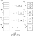
- FIG. 1 shows conventional designs of computer chassis, according to the prior art.
- FIG. 1 shows chassis in a first design 102 (unloaded 102a and loaded 102b), a second design 104 (unloaded 104a and loaded 104b), a third design 106 (unloaded 106a and loaded 106b), and a fourth design 108 (unloaded 108a and loaded 108b).
- FIG. 1 also shows a first size sled 110, a second size sled 112, and a third size sled 114.
- the first design 102 provides a three-partition chassis configured to receive three sleds of a first size 110.
- the second design 104 provides a two-partition chassis configured to receive a second size sled 112 above a first size sled 110.
- the third design 106 provides a two-partition chassis configured to receive a second size sled 112 below a first size sled 110.
- the fourth design 108 provides a single-partition chassis configured to receive a third size sled 114.
- the computer chassis 102, 104, 106, and 108 can only receive sleds 110, 112, and 114 according to their predetermined sizes.
- second size sled 112 and third size sled 114 cannot fit into chassis 102 because they are too large for the three partitions.
- chassis 108 can only receive one sled 110, 112, or 114, regardless of the sled size, because there is no other support in the chassis 108 to receive another sled 110, 112, or 114.
- chassis designs do not allow flexible sled management because of the rigidity of their predetermined designs. If a user has a chassis 102 and wishes to replace two of the three first size sleds 110 with a second size sled 112, the user must remove all first size sleds 110, replace the chassis 102 with a chassis 104, and replace the chosen sleds.
- FIG. 2 shows an exemplary chassis 202 which can support a variety of loaded configurations (202c, 202d, 202e, and 202f) for sleds 110, 112, and 114.
- Chassis 202 includes pairs of rail brackets 204. Although each chassis 202 is shown to have two pairs of rail brackets 204, the present disclosure contemplates that any number of pairs can be provided for in an exemplary chassis 202, so long as there is at least one pair 204. Each pair 204 can be at an equal height 206 from the bottom of the chassis. In some examples where there are more than one pair of rail brackets 204 in a computer chassis, each pair 204 can be at a set height 206 (as seen in FIG. 2 ). In other examples (not shown), the height 206 can be variable for each pair 204. For example, the set height 206 can be a height of the first size sled 110. Each rail bracket 204 can extend along a width of the chassis 202 (as pictured in FIG. 3 ). Therefore, the pairs of rail brackets 204 can allow chassis 202 to receive any sled 110, 112, or 114.
- chassis 202 can hold three first size sleds 110, where two first size sleds 110 rests on top of rail brackets pairs 204a and 204b and a third first size sled 110 rests on top of a bottom surface 206 of chassis 202.
- chassis 202 can hold a second size sled 112 on top of a second pair of rail brackets 204b which a first size sled 110 rests on bottom surface 206.
- chassis 202 can hold a second size sled 112 resting on bottom surface 206 and a first size sled 110 resting on a first pair of rail brackets 204a.
- chassis 202 can hold a third size sled 114 resting on bottom surface 206.
- Chassis 202 can provide for a variety of loaded configurations 202c, 202d, 202e, and 202f, according to the needs of a system. Chassis 202 allows individual sleds 110, 112, and 114 to be replaced without having to replace the chassis 202. For example, chassis 202 can easily transition between configuration 202c to configuration 202d by removing first size sleds 110 resting on rail brackets 204a and 204b and installing second size sled 112 on rail brackets 204b. This chassis 202 provides substantial benefits over conventional designs that otherwise do not allow for easy replacement of sleds.
- first size sleds 110 can be 1U sleds
- second size sleds 112 can be 2U sleds
- third size sleds 114 can be 3U sleds.
- 1U sleds, 2U sleds, and 3U sleds are specifically identified, the present disclosure contemplates that any sleds can be used.
- FIG. 3 shows an exemplary system 300, according to an embodiment of the present disclosure.
- System 300 can include many components and similar labels to FIGs. 1 and 2 .
- system 300 can include chassis 302, tray bases 306, a first rear bracket 308, a second rear bracket 310, and main boards 312.
- System 300 can include a chassis 302 with two partitions 302a and 302b, where each partition 302a and 302b can receive a sled 110 or 112.
- Each partition 302a and 302b can have a single pair of rail brackets 204 extending along a length of the partition 302a and 302b.
- a single rail bracket 204 of each pair is shown (e.g., on sides 302d and 302e)
- each rail bracket can have a corresponding member on an opposing side (e.g., sides 302f and 302g, respectively) of partitions 302a and 302b.
- partitions 302a and 302b can have any number of pairs of rail brackets 204 (e.g., as discussed above with respect to FIG. 2 ).
- system 300 only shows two partitions 302a and 302b, chassis 302 can have any number of partitions.
- System 300 can additionally provide for sleds 110 and 112, where each sled has a tray base 306 and a main board 312.
- Tray base 306 provides structural support to the main boards 312 and any computer components hosted on the main boards 312.
- the main boards 312 can mount any computer components that are greater than a 1U sled size.
- System 300 can further include a first rear bracket 308 for first size sled 110 and a second rear bracket 310 for second size sled 112.
- Rear brackets 308 and 310 can support additional plugged in components, provide electro-magnetic interference shielding, and prevent a user from directly contacting a printed circuit board.
- the rear brackets 308 and 310 are directly attached to the tray base 306, and, in other instances, the rear brackets 308 and 310 can be attached to computer components hosted on the main board 312.
- chassis 302 can receive a second size sled 112 into first partition 302a and a first size sled 110 into second partition 302b.
- the first size sled 110 can rest on bottom surface 302c of chassis 302 or along a pair of rails 204.
- the second size sled 112 can have a similar height 314 to a height 316 of chassis 302.
- FIG. 3 demonstrates that either sled 110 and 112 can fit into either partition 302a and 302b because the partitions have the same design and can receive a sled of either size. Therefore, system 300 presents advantages over conventional chassis designs which do not allow for flexible management of which sleds go into which parts of the chassis.
- FIG. 4A shows a front perspective view of an exemplary system 400A, according to an embodiment of the present disclosure.
- System 400A can include many components and similar labels to components in FIGs. 1-3 .
- system 400A shows end portions 402 and a middle portion 404 of rear bracket 310.
- End portions 402 can have a lower height than a set height 406 of rail brackets 204, while middle portion 404 can have a height larger than set height 406. This lower height of the end portions 402 can allow rear bracket 310 to slide into chassis 302, while the rear bracket 310 still protects the sled and any computer components on the sled (not shown).
- chassis 302 can receive sleds of a first size 110 and a second size 112.
- the present disclosure contemplates that chassis 302 can receive sleds of any size, so long as a height of the sled is not larger than a height of the chassis 302.
- FIG. 4B shows a side perspective view of an exemplary 2U sled and rear bracket 400B
- FIG. 4C shows a side perspective view of an exemplary 1U sled and rear bracket 400C, according to embodiments of the present disclosure.
- FIGs. 4B and 4C can include many components and similar labels to components in FIGs. 1-3 . Additionally, FIGs. 4B and 4C show front perspectives 308a and 310a of rear brackets 308 and 310. FIGs. 4B-4C demonstrate that the same tray base 306 and main board 312 can be used for each sled 110 and 112.
- FIG. 5A shows an exemplary partitioned chassis in a loaded configuration 500A
- FIG. 5B shows an exemplary chassis in a partially loaded configuration 500B, according embodiments of the present disclosure.
- FIGs. 5A-5B can include many components and similar labels to components in FIGs. 1-4C .
- FIGs. 5A-5B show how chassis 302 can hold a second size sled 112 in partition 302a and two first size sleds 110 in partition 302b.
- FIG. 5B shows how each sled 110a, 110b, and 112 can be pulled into and out of the chassis independently of each other. For example, sled 112 is pulled half way out of chassis 302; bottom sled 110 is pulled a small amount out of chassis 302; and top sled 110 remains in a loaded configuration.
- FIGs. 5A-5B show how a second size sled 112 can be replaced with two first size sleds 110 without having to replace the entire chassis 302 and remove any other existing sleds (e.g., the two sleds 110 in partition 302b) from the chassis 302.
Landscapes
- Engineering & Computer Science (AREA)
- Theoretical Computer Science (AREA)
- General Engineering & Computer Science (AREA)
- Computer Hardware Design (AREA)
- Power Engineering (AREA)
- Human Computer Interaction (AREA)
- Physics & Mathematics (AREA)
- General Physics & Mathematics (AREA)
- Microelectronics & Electronic Packaging (AREA)
- Drawers Of Furniture (AREA)
- Casings For Electric Apparatus (AREA)
- Mounting Components In General For Electric Apparatus (AREA)
Abstract

Description
- The present disclosure relates to a computer chassis configured to hold sleds of different sizes.
- Computer chassis can be used in rack systems to hold a variety of computer components and of many different sizes. For example, a single computer chassis can hold multiple sleds, where each sled is sized to hold specific computer components. Conventional computer chassis can hold, for example, a 1U sled, a 2U sled, and/or a 3U sled.
- In order to hold sleds of different sizes within one computer chassis, conventional chassis need to be permanently configured with partitions according to the sled size. Partitions provide the structural support for a computer chassis to hold more than one sled. For example, one computer chassis can be configured with three separate, permanent partitions to support three 1U sleds. In another example, one computer chassis can be configured with two separate, permanent partitions to support one 1U sled and one 2U sled. In a third example, one computer chassis can be configured without any partitions to support one 3U sled. The configuration of permanent partitions in a computer chassis prevent the same computer chassis from holding sleds of a first size and then sleds of a second size.
- For example, a 2U sled is about twice as large as a 1U sled, and a 3U sled is about three times as large as a 1U sled. Therefore, a computer chassis which is configured to hold three 1U sleds can never receive either a 2U sled or a 3U sled. In a similar problem, a computer chassis which is configured to hold a single 3U sled can never hold three 1U sleds, because such a computer chassis does not have partitions to support the separation for each of the three 1U sleds.
- These chassis designs force users to maintain a large variety of chassis bodies, configured to support every combination of sled sizes. If a single sled needs to be switched out with another sled of a different size, the entire computer chassis needs to be replaced. This results in high costs because all possible chassis sizes must be supported. This also results in additional burdens because any size change in the installed equipment necessitates replacing the entire computer chassis.
- Therefore, what is needed is a computer chassis design that does not require switching out the entire chassis when replacing a first sled with a second sled of a different size.
- The various examples of the present disclosure are directed towards a computer chassis. In a first embodiment of the present disclosure, the computer chassis can be a chassis body with at least one pair of rail brackets. A first rail bracket in a pair can be located on a first side of the chassis body, and a second rail bracket can be located on a second side of the chassis body, where the second side and the first side are opposing sides of the chassis body. The first and second rail brackets can be at a set height from a bottom surface of the chassis body.
- In some examples, the chassis body can include at least two partitions. The pairs of rail brackets can be positioned along the sides of each partition.
- In some examples, the computer chassis can also include at least one sled. The sled can hold at least one computer component. A size of the sled can correspond to the size of the at least one computer component.
- In some examples, each sled can also include at least one rear bracket. An exemplary rear bracket can couple with a sled. End portions of the rear bracket can have a lower height than the distance between a chassis base and the at least one pair of rail brackets ("rail bracket set height"). A middle portion of the rear bracket can have a height larger than the rail bracket set height.
- In some examples, a first sled of the at least one sled can have a different size than a second sled of the at least one sled. In some examples, the at least one sled can be a 1U sled, a 2U sled, or a 3U sled. In some examples, each of the sleds can move into and out of the chassis body independent of any remaining sleds in the chassis body.
- A second embodiment of the present disclosure can provide for a chassis assembly. The chassis assembly can include a chassis body, at least one sled, and at least one rear bracket. The chassis body can include at least one pair of rail brackets. A first rail bracket in a pair can be on a first side of the chassis body, and a second bracket in the pair can be on a second side of the chassis body. The first side and the second side can be opposing sides of the chassis body. The at least one sled can hold at least one computer component. The sled can have a size corresponding to the at least one computer component in the sled. Additional examples of the second embodiment can be as described above with respect to the first embodiment.
- A third embodiment of the present disclosure can provide for a rack system housing a plurality of computer chassis. The rack system can include a plurality of chassis bodies, a plurality of sleds, and a plurality of rear brackets. Each chassis body can include at least one pair of rail brackets. A first bracket in the at least one pair can be on a first side of each chassis body, and a second bracket in the pair can be on a second side of the chassis body. The first side and the second side can be opposing sides of the chassis body. Each chassis body can be configured to receive at least one sled. Each of the plurality of sleds can hold at least one computer component. Each sled can be sized according to the size of the at least one computer component held by the sled. Each of the plurality of rear brackets can be configured to couple with one of the plurality of sleds. Additional examples of the third embodiment can be as described above with respect to the first embodiment.
- The above summary is not intended to represent each embodiment or every aspect of the present disclosure. Rather, the foregoing summary merely provides an example of some of the novel aspects and features set forth herein. The above features and advantages, and other features and advantages of the present disclosure, will be readily apparent from the following detailed description of representative embodiments and modes for carrying out the present invention, when taken in connection with the accompanying drawings and the appended claims.
- The accompanying drawings exemplify the embodiments of the present invention and, together with the description, serve to explain and illustrate principles of the invention. The drawings are intended to illustrate major features of the exemplary embodiments in a diagrammatic manner. The drawings are not intended to depict every feature of actual embodiments nor relative dimensions of the depicted elements, and are not drawn to scale.
-
FIG. 1 shows conventional designs of computer chassis, according to the prior art. -
FIG. 2 shows an exemplary design of a computer chassis with various sled configurations, according to an embodiment of the present disclosure. -
FIG. 3 shows an exemplary set of sleds loading into a chassis, according to an embodiment of the present disclosure. -
FIG. 4A shows a front side perspective view of an exemplary partitioned computer chassis, according to an embodiment of the present disclosure. -
FIG. 4B shows a side perspective view of an exemplary 2U sled and rear bracket, andFIG. 4C shows a side perspective view of an exemplary 1U sled and rear bracket, according to embodiments of the present disclosure. -
FIG. 5A shows an exemplary partitioned chassis in a loaded configuration, andFIG. 5B shows an exemplary chassis in a partially loaded configuration, according to embodiments of the present disclosure. - The present invention is described with reference to the attached figures, where like reference numerals are used throughout the figures to designate similar or equivalent elements. The figures are not drawn to scale, and are provided merely to illustrate the instant invention. Several aspects of the invention are described below with reference to example applications for illustration. It should be understood that numerous specific details, relationships, and methods are set forth to provide a full understanding of the invention. One having ordinary skill in the relevant art, however, will readily recognize that the invention can be practiced without one or more of the specific details, or with other methods. In other instances, well-known structures or operations are not shown in detail to avoid obscuring the invention. The present invention is not limited by the illustrated ordering of acts or events, as some acts may occur in different orders and/or concurrently with other acts or events. Furthermore, not all illustrated acts or events are required to implement a methodology in accordance with the present invention.
- The present disclosure is directed to a computer chassis with rail brackets along the side that allow sleds to slide into and out of the computer chassis. The design additionally allows sleds of any size to be used in the exemplary chassis. This feature is provided for because the chassis does not have permanent partitions that allow for only heights of certain sleds. Therefore, an exemplary chassis, according to an embodiment of the present disclosure, can provide for a variety of sled configurations, where the sleds can have different sizes.
-
FIG. 1 shows conventional designs of computer chassis, according to the prior art.FIG. 1 shows chassis in a first design 102 (unloaded 102a and loaded 102b), a second design 104 (unloaded 104a and loaded 104b), a third design 106 (unloaded 106a and loaded 106b), and a fourth design 108 (unloaded 108a and loaded 108b).FIG. 1 also shows afirst size sled 110, asecond size sled 112, and athird size sled 114. - The first design 102 provides a three-partition chassis configured to receive three sleds of a
first size 110. The second design 104 provides a two-partition chassis configured to receive asecond size sled 112 above afirst size sled 110. The third design 106 provides a two-partition chassis configured to receive asecond size sled 112 below afirst size sled 110. The fourth design 108 provides a single-partition chassis configured to receive athird size sled 114. - As shown by both the loaded
positions positions sleds second size sled 112 andthird size sled 114 cannot fit into chassis 102 because they are too large for the three partitions. In another example, chassis 108 can only receive onesled sled - Therefore, conventional chassis designs do not allow flexible sled management because of the rigidity of their predetermined designs. If a user has a chassis 102 and wishes to replace two of the three first size sleds 110 with a
second size sled 112, the user must remove all first size sleds 110, replace the chassis 102 with a chassis 104, and replace the chosen sleds. - In response to the limitations of conventional chassis designs, the present disclosure provides a chassis design with rail brackets which provide for a single chassis design that can receive a variety of sled configurations.
FIG. 2 shows anexemplary chassis 202 which can support a variety of loaded configurations (202c, 202d, 202e, and 202f) forsleds -
Chassis 202 includes pairs ofrail brackets 204. Although eachchassis 202 is shown to have two pairs ofrail brackets 204, the present disclosure contemplates that any number of pairs can be provided for in anexemplary chassis 202, so long as there is at least onepair 204. Eachpair 204 can be at anequal height 206 from the bottom of the chassis. In some examples where there are more than one pair ofrail brackets 204 in a computer chassis, eachpair 204 can be at a set height 206 (as seen inFIG. 2 ). In other examples (not shown), theheight 206 can be variable for eachpair 204. For example, theset height 206 can be a height of thefirst size sled 110. Eachrail bracket 204 can extend along a width of the chassis 202 (as pictured inFIG. 3 ). Therefore, the pairs ofrail brackets 204 can allowchassis 202 to receive anysled - In a first loaded
configuration 202c,chassis 202 can hold three first size sleds 110, where two first size sleds 110 rests on top of rail brackets pairs 204a and 204b and a thirdfirst size sled 110 rests on top of abottom surface 206 ofchassis 202. In a second loadedconfiguration 202d,chassis 202 can hold asecond size sled 112 on top of a second pair ofrail brackets 204b which afirst size sled 110 rests onbottom surface 206. In a thirdloaded configuration 202e,chassis 202 can hold asecond size sled 112 resting onbottom surface 206 and afirst size sled 110 resting on a first pair ofrail brackets 204a. In a fourth loadedconfiguration 202f,chassis 202 can hold athird size sled 114 resting onbottom surface 206. -
Chassis 202 can provide for a variety of loadedconfigurations Chassis 202 allowsindividual sleds chassis 202. For example,chassis 202 can easily transition betweenconfiguration 202c toconfiguration 202d by removing first size sleds 110 resting onrail brackets second size sled 112 onrail brackets 204b. Thischassis 202 provides substantial benefits over conventional designs that otherwise do not allow for easy replacement of sleds. - In some examples of the present disclosure, first size sleds 110 can be 1U sleds, second size sleds 112 can be 2U sleds, and third size sleds 114 can be 3U sleds. Although 1U sleds, 2U sleds, and 3U sleds are specifically identified, the present disclosure contemplates that any sleds can be used.
-
FIG. 3 shows anexemplary system 300, according to an embodiment of the present disclosure.System 300 can include many components and similar labels toFIGs. 1 and2 . In addition,system 300 can includechassis 302,tray bases 306, a firstrear bracket 308, a secondrear bracket 310, andmain boards 312. -
System 300 can include achassis 302 with twopartitions partition sled partition rail brackets 204 extending along a length of thepartition single rail bracket 204 of each pair is shown (e.g., onsides partitions system 300 only shows a single pair ofrail brackets 204 for eachpartition partitions FIG. 2 ). Althoughsystem 300 only shows twopartitions chassis 302 can have any number of partitions. -
System 300 can additionally provide forsleds tray base 306 and amain board 312.Tray base 306 provides structural support to themain boards 312 and any computer components hosted on themain boards 312. Themain boards 312 can mount any computer components that are greater than a 1U sled size.System 300 can further include a firstrear bracket 308 forfirst size sled 110 and a secondrear bracket 310 forsecond size sled 112.Rear brackets rear brackets tray base 306, and, in other instances, therear brackets main board 312. - For example,
chassis 302 can receive asecond size sled 112 intofirst partition 302a and afirst size sled 110 intosecond partition 302b. Thefirst size sled 110 can rest onbottom surface 302c ofchassis 302 or along a pair ofrails 204. Thesecond size sled 112 can have asimilar height 314 to aheight 316 ofchassis 302.FIG. 3 demonstrates that eithersled partition system 300 presents advantages over conventional chassis designs which do not allow for flexible management of which sleds go into which parts of the chassis. -
FIG. 4A shows a front perspective view of anexemplary system 400A, according to an embodiment of the present disclosure.System 400A can include many components and similar labels to components inFIGs. 1-3 . Additionally,system 400A showsend portions 402 and amiddle portion 404 ofrear bracket 310.End portions 402 can have a lower height than aset height 406 ofrail brackets 204, whilemiddle portion 404 can have a height larger than setheight 406. This lower height of theend portions 402 can allowrear bracket 310 to slide intochassis 302, while therear bracket 310 still protects the sled and any computer components on the sled (not shown). - Therefore,
chassis 302 can receive sleds of afirst size 110 and asecond size 112. The present disclosure contemplates thatchassis 302 can receive sleds of any size, so long as a height of the sled is not larger than a height of thechassis 302. -
FIG. 4B shows a side perspective view of an exemplary 2U sled andrear bracket 400B, andFIG. 4C shows a side perspective view of an exemplary 1U sled andrear bracket 400C, according to embodiments of the present disclosure.FIGs. 4B and 4C can include many components and similar labels to components inFIGs. 1-3 . Additionally,FIGs. 4B and 4C showfront perspectives rear brackets FIGs. 4B-4C demonstrate that thesame tray base 306 andmain board 312 can be used for eachsled -
FIG. 5A shows an exemplary partitioned chassis in a loadedconfiguration 500A, andFIG. 5B shows an exemplary chassis in a partially loadedconfiguration 500B, according embodiments of the present disclosure.FIGs. 5A-5B can include many components and similar labels to components inFIGs. 1-4C .FIGs. 5A-5B show howchassis 302 can hold asecond size sled 112 inpartition 302a and two first size sleds 110 inpartition 302b.FIG. 5B shows how eachsled sled 112 is pulled half way out ofchassis 302;bottom sled 110 is pulled a small amount out ofchassis 302; andtop sled 110 remains in a loaded configuration. - Therefore,
FIGs. 5A-5B show how asecond size sled 112 can be replaced with two first size sleds 110 without having to replace theentire chassis 302 and remove any other existing sleds (e.g., the twosleds 110 inpartition 302b) from thechassis 302. - While various examples of the present invention have been described above, it should be understood that they have been presented by way of example only, and not limitation. Numerous changes to the disclosed examples can be made in accordance with the disclosure herein without departing from the spirit or scope of the invention. Thus, the breadth and scope of the present invention should not be limited by any of the above described examples. Rather, the scope of the invention should be defined in accordance with the following claims and their equivalents.
- Although the invention has been illustrated and described with respect to one or more implementations, equivalent alterations and modifications will occur to others skilled in the art upon the reading and understanding of this specification and the annexed drawings. In addition, while a particular feature of the invention may have been disclosed with respect to only one of several implementations, such feature may be combined with one or more other features of the other implementations as may be desired and advantageous for any given or particular application.
- The terminology used herein is for the purpose of describing particular examples only and is not intended to be limiting of the invention. As used herein, the singular forms "a," "an," and "the" are intended to include the plural forms as well, unless the context clearly indicates otherwise. Furthermore, to the extent that the terms "including," "includes," "having," "has," "with," or variants thereof, are used in either the detailed description and/or the claims, such terms are intended to be inclusive in a manner similar to the term "comprising."
- Unless otherwise defined, all terms (including technical and scientific terms) used herein have the same meaning as commonly understood by one of ordinary skill in the art to which this invention belongs. Furthermore, terms, such as those defined in commonly used dictionaries, should be interpreted as having a meaning that is consistent with their meaning in the context of the relevant art, and will not be interpreted in an idealized or overly formal sense unless expressly so defined herein.
Claims (15)
- A computer chassis, comprising:a chassis body comprising at least one pair of rail brackets,wherein a first rail bracket in a pair of the at least one pair of rail brackets is on a first side of the chassis body, and a second rail bracket in the pair of the at least one pair of rail brackets is on a second side of the chassis body, the second side and the first side being on opposite sides of the chassis body,wherein the first rail bracket and the second rail bracket are at a set height from a bottom surface of the chassis body.
- The computer chassis of claim 1, wherein the chassis body comprises at least two partitions, wherein the at least one pair of rail brackets is configured along sides of each partition.
- The computer chassis of claim 1, wherein the computer chassis further comprises at least one sled, wherein each of the at least one sled holds at least one computer component, and wherein each of the at least one sled has a size corresponding to the at least one computer component.
- The computer chassis of claim 3, wherein the at least one sled further comprises at least one rear bracket, and/or wherein a first of the at least one sled has a different size than a second of the at least one sled, and/or wherein the at least one sled comprises at least one of: a 1U sled, a 2U sled, and a 3U sled, and/or wherein each of the at least one sled is configured to move into and out of the chassis body independently.
- The computer chassis of any of claims 1 to 4, wherein end portions of the at least one rear bracket has a lower height than a distance between a chassis base and the at least one pair of rail brackets.
- The computer chassis of claim, 5 wherein a middle portion of the at least one rear bracket has a height larger than the set height.
- A chassis assembly, comprising:a chassis body comprising at least one pair of rail brackets, wherein a first bracket in a pair of the at least one pair of rail brackets is on a first side of the chassis body, and a second bracket in the pair of the at least one pair of rail brackets is on a second side of the chassis body, the second side and the first side being on opposite sides of the chassis body; andat least one sled, wherein each of the at least one sled holds at least one computer component, and wherein each of the at least one sled has a size corresponding to the at least one computer component.
- The chassis assembly of claim 7, wherein the chassis body comprises more than one partition, wherein the at least one pair of rail brackets is configured along sides of each partition.
- The chassis assembly of claim 7, wherein end portions of the at least one rear bracket have a lower height than a distance between a chassis base and the at least one pair of rail brackets.
- The chassis assembly of claim 9, wherein a middle portion of the at least one rear bracket has a height larger than a distance between a chassis base and the at least one pair of rail brackets, and/or wherein a first of the at least one sled has a different size than a second of the at least one sled and/or the chassis assembly further comprises at least one rear bracket, wherein each of the at least one rear bracket is configured to couple with one of the at least one sled.
- A rack system for housing a plurality of computer chassis, comprising:a plurality of chassis bodies, wherein each chassis body in the plurality of chassis bodies comprises at least one pair of rail brackets, wherein a first bracket in a pair of the at least one pair of rail brackets is on a first side of each chassis body, and a second bracket in the pair of the at least one pair of rail brackets is on a second side of each chassis body, wherein the first side and the second side are on opposing sides of each chassis body, and wherein each chassis body is configured to receive at least one sled; anda plurality of sleds, wherein each of the at least one sled holds at least one computer component, and wherein each of the plurality of sleds has a size corresponding to the at least one computer component.
- The rack system of claim 11, wherein at least one of the plurality of chassis bodies comprises more than one partition, wherein the at least one pair of rail brackets is configured along sides of each partition.
- The rack system of claim 11, wherein end portions of the plurality of rear brackets have a lower height than a distance between a chassis base and one pair of the at least one pair of rail brackets.
- The rack system of claim 13, wherein a middle portion of the plurality of rear brackets has a height larger than a distance between a chassis base and the at least one pair of rail brackets.
- The rack system of any of claims 11 to 14, further comprising a plurality of rear brackets, wherein each of the plurality of rear brackets is configured to couple with one of the plurality of sleds.
Applications Claiming Priority (1)
| Application Number | Priority Date | Filing Date | Title |
|---|---|---|---|
| US16/291,913 US10624227B1 (en) | 2019-03-04 | 2019-03-04 | Computer chassis with rail brackets |
Publications (1)
| Publication Number | Publication Date |
|---|---|
| EP3705977A1 true EP3705977A1 (en) | 2020-09-09 |
Family
ID=67262098
Family Applications (1)
| Application Number | Title | Priority Date | Filing Date |
|---|---|---|---|
| EP19185892.7A Withdrawn EP3705977A1 (en) | 2019-03-04 | 2019-07-11 | Computer chassis with rail brackets |
Country Status (5)
| Country | Link |
|---|---|
| US (1) | US10624227B1 (en) |
| EP (1) | EP3705977A1 (en) |
| JP (1) | JP7017550B2 (en) |
| CN (1) | CN111651006B (en) |
| TW (1) | TWI720476B (en) |
Families Citing this family (2)
| Publication number | Priority date | Publication date | Assignee | Title |
|---|---|---|---|---|
| US10579110B1 (en) * | 2019-03-18 | 2020-03-03 | Quanta Computer Inc. | Computer chassis with sliding bracket |
| US12458740B2 (en) * | 2022-03-10 | 2025-11-04 | Terumo Bct, Inc. | Modular serviceability sleds and interconnections |
Citations (4)
| Publication number | Priority date | Publication date | Assignee | Title |
|---|---|---|---|---|
| US20080043451A1 (en) * | 2006-08-17 | 2008-02-21 | Fujitsu Limited | Plug-in unit-mounting structure and electronic apparatus |
| US20130141887A1 (en) * | 2011-12-02 | 2013-06-06 | Hon Hai Precision Industry Co., Ltd. | Chassis for electronic device |
| US20180007808A1 (en) * | 2016-06-30 | 2018-01-04 | Fujitsu Limited | Information processing apparatus, method for managing, non-transitory computer-readable recording medium having stored therein management program, and method for specifying installing position of electronic device |
| US20190059172A1 (en) * | 2017-08-17 | 2019-02-21 | Cisco Technology, Inc. | Configurable module guides for modular electronic system |
Family Cites Families (10)
| Publication number | Priority date | Publication date | Assignee | Title |
|---|---|---|---|---|
| JP2000307275A (en) * | 1999-04-16 | 2000-11-02 | Pfu Ltd | Mounting structure of rack mount device |
| US7639492B2 (en) * | 2007-04-27 | 2009-12-29 | Hewlett-Packard Development Company, L.P. | Drive carrier for computer systems |
| CN201622509U (en) * | 2010-03-02 | 2010-11-03 | 环达电脑(上海)有限公司 | Assembling structure of multiple servers and machine boxes |
| US9095070B2 (en) * | 2011-12-05 | 2015-07-28 | Amazon Technologies, Inc. | Partial-width rack-mounted computing devices |
| WO2013090862A1 (en) * | 2011-12-15 | 2013-06-20 | Amazon Technologies, Inc. | Reconfigurable shelf for computing modules |
| US9713279B2 (en) * | 2014-12-30 | 2017-07-18 | Quanta Computer Inc. | Front access server |
| US9958911B2 (en) * | 2015-03-31 | 2018-05-01 | Dell Products, L.P. | 1U to NxU expandable server chassis using interchangeable flexible covers of varying size |
| US10042396B1 (en) * | 2017-08-17 | 2018-08-07 | Cisco Technology, Inc. | Configurable module guides for modular electronic system |
| CN207589364U (en) * | 2017-12-06 | 2018-07-06 | 新汉股份有限公司 | The positioning structure of the support slide rail of the server cabinet |
| CN108932038B (en) * | 2018-09-26 | 2023-06-16 | 郑州云海信息技术有限公司 | Multi-adaptability bracket capable of inhibiting electromagnetic radiation of hard disk |
-
2019
- 2019-03-04 US US16/291,913 patent/US10624227B1/en active Active
- 2019-05-08 TW TW108115803A patent/TWI720476B/en active
- 2019-05-22 CN CN201910428028.8A patent/CN111651006B/en active Active
- 2019-07-11 EP EP19185892.7A patent/EP3705977A1/en not_active Withdrawn
- 2019-11-05 JP JP2019200925A patent/JP7017550B2/en active Active
Patent Citations (4)
| Publication number | Priority date | Publication date | Assignee | Title |
|---|---|---|---|---|
| US20080043451A1 (en) * | 2006-08-17 | 2008-02-21 | Fujitsu Limited | Plug-in unit-mounting structure and electronic apparatus |
| US20130141887A1 (en) * | 2011-12-02 | 2013-06-06 | Hon Hai Precision Industry Co., Ltd. | Chassis for electronic device |
| US20180007808A1 (en) * | 2016-06-30 | 2018-01-04 | Fujitsu Limited | Information processing apparatus, method for managing, non-transitory computer-readable recording medium having stored therein management program, and method for specifying installing position of electronic device |
| US20190059172A1 (en) * | 2017-08-17 | 2019-02-21 | Cisco Technology, Inc. | Configurable module guides for modular electronic system |
Also Published As
| Publication number | Publication date |
|---|---|
| TW202034757A (en) | 2020-09-16 |
| CN111651006A (en) | 2020-09-11 |
| TWI720476B (en) | 2021-03-01 |
| JP2020144836A (en) | 2020-09-10 |
| US10624227B1 (en) | 2020-04-14 |
| CN111651006B (en) | 2022-05-27 |
| JP7017550B2 (en) | 2022-02-08 |
Similar Documents
| Publication | Publication Date | Title |
|---|---|---|
| US8047383B2 (en) | Rackmount system including conversion rail | |
| US5708563A (en) | Computer with modular removable card cage | |
| US9462725B2 (en) | Server rack and its server device | |
| US7042717B2 (en) | Data storage system with a removable backplane having a array of disk drives | |
| US6018456A (en) | Enclosure for removable computer peripheral equipment | |
| KR930001355B1 (en) | Exterior for small packaging of electronic parts | |
| US6320760B1 (en) | Multiple PCI card support | |
| US9417664B1 (en) | Rack power and data bus | |
| US20080298014A1 (en) | Modular electronic enclosure | |
| US8054645B2 (en) | Plug-in unit-mounting structure and electronic apparatus | |
| US10383247B2 (en) | High density chassis for a server rack | |
| EP0173056A2 (en) | A data processing terminal support system operable to convert the terminal from an integrated to a distributed configuration and vice versa | |
| US6646890B1 (en) | Mounting of mezzanine circuit boards to a base board | |
| US4779744A (en) | Guide rail for supporting boards | |
| US5224020A (en) | Electronic apparatus having modular front and back functional units and electrical distribution unit including a fan therebetween | |
| US10624227B1 (en) | Computer chassis with rail brackets | |
| US6853548B2 (en) | 1U rack mount equipment enclosure with increased structural support | |
| KR20150031297A (en) | Electronic interconnect method and apparatus | |
| US20130284682A1 (en) | Chassis card cage | |
| US4896248A (en) | Module frame for receiving insertable electrical printed circuit boards | |
| US20070158280A1 (en) | Computer server rack system | |
| US6356457B1 (en) | Circuit card support mechanism and method | |
| US4821149A (en) | Substrate mounting device | |
| US20050078437A1 (en) | Variable chassis for interface card modules | |
| US9313557B1 (en) | Rack with mounting column |
Legal Events
| Date | Code | Title | Description |
|---|---|---|---|
| PUAI | Public reference made under article 153(3) epc to a published international application that has entered the european phase |
Free format text: ORIGINAL CODE: 0009012 |
|
| STAA | Information on the status of an ep patent application or granted ep patent |
Free format text: STATUS: THE APPLICATION HAS BEEN PUBLISHED |
|
| AK | Designated contracting states |
Kind code of ref document: A1 Designated state(s): AL AT BE BG CH CY CZ DE DK EE ES FI FR GB GR HR HU IE IS IT LI LT LU LV MC MK MT NL NO PL PT RO RS SE SI SK SM TR |
|
| AX | Request for extension of the european patent |
Extension state: BA ME |
|
| STAA | Information on the status of an ep patent application or granted ep patent |
Free format text: STATUS: REQUEST FOR EXAMINATION WAS MADE |
|
| 17P | Request for examination filed |
Effective date: 20201103 |
|
| RBV | Designated contracting states (corrected) |
Designated state(s): AL AT BE BG CH CY CZ DE DK EE ES FI FR GB GR HR HU IE IS IT LI LT LU LV MC MK MT NL NO PL PT RO RS SE SI SK SM TR |
|
| STAA | Information on the status of an ep patent application or granted ep patent |
Free format text: STATUS: EXAMINATION IS IN PROGRESS |
|
| 17Q | First examination report despatched |
Effective date: 20211027 |
|
| STAA | Information on the status of an ep patent application or granted ep patent |
Free format text: STATUS: THE APPLICATION IS DEEMED TO BE WITHDRAWN |
|
| 18D | Application deemed to be withdrawn |
Effective date: 20230822 |