EP3705912A1 - Terrain prediction method, device and system, and drone - Google Patents
Terrain prediction method, device and system, and drone Download PDFInfo
- Publication number
- EP3705912A1 EP3705912A1 EP17935388.3A EP17935388A EP3705912A1 EP 3705912 A1 EP3705912 A1 EP 3705912A1 EP 17935388 A EP17935388 A EP 17935388A EP 3705912 A1 EP3705912 A1 EP 3705912A1
- Authority
- EP
- European Patent Office
- Prior art keywords
- ranging data
- pieces
- ranging
- radar
- determining
- Prior art date
- Legal status (The legal status is an assumption and is not a legal conclusion. Google has not performed a legal analysis and makes no representation as to the accuracy of the status listed.)
- Withdrawn
Links
- 238000000034 method Methods 0.000 title claims abstract description 68
- 238000012886 linear function Methods 0.000 claims description 66
- 230000006870 function Effects 0.000 claims description 15
- 238000004590 computer program Methods 0.000 claims description 10
- 238000009499 grossing Methods 0.000 claims description 7
- 230000008859 change Effects 0.000 abstract description 6
- 238000010586 diagram Methods 0.000 description 9
- 230000008569 process Effects 0.000 description 9
- 238000005516 engineering process Methods 0.000 description 5
- 230000001133 acceleration Effects 0.000 description 4
- 239000007788 liquid Substances 0.000 description 4
- 239000007921 spray Substances 0.000 description 4
- RZVHIXYEVGDQDX-UHFFFAOYSA-N 9,10-anthraquinone Chemical compound C1=CC=C2C(=O)C3=CC=CC=C3C(=O)C2=C1 RZVHIXYEVGDQDX-UHFFFAOYSA-N 0.000 description 3
- 230000000694 effects Effects 0.000 description 3
- 238000005259 measurement Methods 0.000 description 3
- 230000008901 benefit Effects 0.000 description 2
- 230000009194 climbing Effects 0.000 description 2
- 210000002304 esc Anatomy 0.000 description 1
- 238000001914 filtration Methods 0.000 description 1
- 238000003306 harvesting Methods 0.000 description 1
- 230000003287 optical effect Effects 0.000 description 1
- 239000000575 pesticide Substances 0.000 description 1
- 230000008054 signal transmission Effects 0.000 description 1
- 239000000126 substance Substances 0.000 description 1
- 230000001960 triggered effect Effects 0.000 description 1
- XLYOFNOQVPJJNP-UHFFFAOYSA-N water Substances O XLYOFNOQVPJJNP-UHFFFAOYSA-N 0.000 description 1
Images


Classifications
-
- G—PHYSICS
- G01—MEASURING; TESTING
- G01S—RADIO DIRECTION-FINDING; RADIO NAVIGATION; DETERMINING DISTANCE OR VELOCITY BY USE OF RADIO WAVES; LOCATING OR PRESENCE-DETECTING BY USE OF THE REFLECTION OR RERADIATION OF RADIO WAVES; ANALOGOUS ARRANGEMENTS USING OTHER WAVES
- G01S13/00—Systems using the reflection or reradiation of radio waves, e.g. radar systems; Analogous systems using reflection or reradiation of waves whose nature or wavelength is irrelevant or unspecified
- G01S13/02—Systems using reflection of radio waves, e.g. primary radar systems; Analogous systems
- G01S13/06—Systems determining position data of a target
- G01S13/08—Systems for measuring distance only
-
- B—PERFORMING OPERATIONS; TRANSPORTING
- B64—AIRCRAFT; AVIATION; COSMONAUTICS
- B64D—EQUIPMENT FOR FITTING IN OR TO AIRCRAFT; FLIGHT SUITS; PARACHUTES; ARRANGEMENT OR MOUNTING OF POWER PLANTS OR PROPULSION TRANSMISSIONS IN AIRCRAFT
- B64D47/00—Equipment not otherwise provided for
-
- B—PERFORMING OPERATIONS; TRANSPORTING
- B64—AIRCRAFT; AVIATION; COSMONAUTICS
- B64U—UNMANNED AERIAL VEHICLES [UAV]; EQUIPMENT THEREFOR
- B64U10/00—Type of UAV
- B64U10/10—Rotorcrafts
- B64U10/13—Flying platforms
- B64U10/16—Flying platforms with five or more distinct rotor axes, e.g. octocopters
-
- B—PERFORMING OPERATIONS; TRANSPORTING
- B64—AIRCRAFT; AVIATION; COSMONAUTICS
- B64U—UNMANNED AERIAL VEHICLES [UAV]; EQUIPMENT THEREFOR
- B64U20/00—Constructional aspects of UAVs
- B64U20/80—Arrangement of on-board electronics, e.g. avionics systems or wiring
- B64U20/83—Electronic components structurally integrated with aircraft elements, e.g. circuit boards carrying loads
-
- B—PERFORMING OPERATIONS; TRANSPORTING
- B64—AIRCRAFT; AVIATION; COSMONAUTICS
- B64U—UNMANNED AERIAL VEHICLES [UAV]; EQUIPMENT THEREFOR
- B64U30/00—Means for producing lift; Empennages; Arrangements thereof
- B64U30/20—Rotors; Rotor supports
- B64U30/21—Rotary wings
-
- B—PERFORMING OPERATIONS; TRANSPORTING
- B64—AIRCRAFT; AVIATION; COSMONAUTICS
- B64U—UNMANNED AERIAL VEHICLES [UAV]; EQUIPMENT THEREFOR
- B64U60/00—Undercarriages
- B64U60/20—Undercarriages specially adapted for uneven terrain
-
- G—PHYSICS
- G01—MEASURING; TESTING
- G01S—RADIO DIRECTION-FINDING; RADIO NAVIGATION; DETERMINING DISTANCE OR VELOCITY BY USE OF RADIO WAVES; LOCATING OR PRESENCE-DETECTING BY USE OF THE REFLECTION OR RERADIATION OF RADIO WAVES; ANALOGOUS ARRANGEMENTS USING OTHER WAVES
- G01S13/00—Systems using the reflection or reradiation of radio waves, e.g. radar systems; Analogous systems using reflection or reradiation of waves whose nature or wavelength is irrelevant or unspecified
- G01S13/02—Systems using reflection of radio waves, e.g. primary radar systems; Analogous systems
- G01S13/06—Systems determining position data of a target
- G01S13/42—Simultaneous measurement of distance and other co-ordinates
- G01S13/426—Scanning radar, e.g. 3D radar
-
- G—PHYSICS
- G01—MEASURING; TESTING
- G01S—RADIO DIRECTION-FINDING; RADIO NAVIGATION; DETERMINING DISTANCE OR VELOCITY BY USE OF RADIO WAVES; LOCATING OR PRESENCE-DETECTING BY USE OF THE REFLECTION OR RERADIATION OF RADIO WAVES; ANALOGOUS ARRANGEMENTS USING OTHER WAVES
- G01S13/00—Systems using the reflection or reradiation of radio waves, e.g. radar systems; Analogous systems using reflection or reradiation of waves whose nature or wavelength is irrelevant or unspecified
- G01S13/88—Radar or analogous systems specially adapted for specific applications
- G01S13/885—Radar or analogous systems specially adapted for specific applications for ground probing
-
- G—PHYSICS
- G01—MEASURING; TESTING
- G01S—RADIO DIRECTION-FINDING; RADIO NAVIGATION; DETERMINING DISTANCE OR VELOCITY BY USE OF RADIO WAVES; LOCATING OR PRESENCE-DETECTING BY USE OF THE REFLECTION OR RERADIATION OF RADIO WAVES; ANALOGOUS ARRANGEMENTS USING OTHER WAVES
- G01S13/00—Systems using the reflection or reradiation of radio waves, e.g. radar systems; Analogous systems using reflection or reradiation of waves whose nature or wavelength is irrelevant or unspecified
- G01S13/88—Radar or analogous systems specially adapted for specific applications
- G01S13/93—Radar or analogous systems specially adapted for specific applications for anti-collision purposes
- G01S13/933—Radar or analogous systems specially adapted for specific applications for anti-collision purposes of aircraft or spacecraft
- G01S13/935—Radar or analogous systems specially adapted for specific applications for anti-collision purposes of aircraft or spacecraft for terrain-avoidance
-
- G—PHYSICS
- G01—MEASURING; TESTING
- G01S—RADIO DIRECTION-FINDING; RADIO NAVIGATION; DETERMINING DISTANCE OR VELOCITY BY USE OF RADIO WAVES; LOCATING OR PRESENCE-DETECTING BY USE OF THE REFLECTION OR RERADIATION OF RADIO WAVES; ANALOGOUS ARRANGEMENTS USING OTHER WAVES
- G01S17/00—Systems using the reflection or reradiation of electromagnetic waves other than radio waves, e.g. lidar systems
- G01S17/02—Systems using the reflection of electromagnetic waves other than radio waves
- G01S17/06—Systems determining position data of a target
- G01S17/42—Simultaneous measurement of distance and other co-ordinates
-
- G—PHYSICS
- G01—MEASURING; TESTING
- G01S—RADIO DIRECTION-FINDING; RADIO NAVIGATION; DETERMINING DISTANCE OR VELOCITY BY USE OF RADIO WAVES; LOCATING OR PRESENCE-DETECTING BY USE OF THE REFLECTION OR RERADIATION OF RADIO WAVES; ANALOGOUS ARRANGEMENTS USING OTHER WAVES
- G01S17/00—Systems using the reflection or reradiation of electromagnetic waves other than radio waves, e.g. lidar systems
- G01S17/88—Lidar systems specially adapted for specific applications
- G01S17/93—Lidar systems specially adapted for specific applications for anti-collision purposes
- G01S17/933—Lidar systems specially adapted for specific applications for anti-collision purposes of aircraft or spacecraft
-
- G—PHYSICS
- G08—SIGNALLING
- G08G—TRAFFIC CONTROL SYSTEMS
- G08G5/00—Traffic control systems for aircraft
- G08G5/50—Navigation or guidance aids
- G08G5/51—Navigation or guidance aids for control when on the ground, e.g. taxiing or rolling
-
- G—PHYSICS
- G08—SIGNALLING
- G08G—TRAFFIC CONTROL SYSTEMS
- G08G5/00—Traffic control systems for aircraft
- G08G5/50—Navigation or guidance aids
- G08G5/55—Navigation or guidance aids for a single aircraft
-
- G—PHYSICS
- G08—SIGNALLING
- G08G—TRAFFIC CONTROL SYSTEMS
- G08G5/00—Traffic control systems for aircraft
- G08G5/50—Navigation or guidance aids
- G08G5/57—Navigation or guidance aids for unmanned aircraft
-
- G—PHYSICS
- G08—SIGNALLING
- G08G—TRAFFIC CONTROL SYSTEMS
- G08G5/00—Traffic control systems for aircraft
- G08G5/70—Arrangements for monitoring traffic-related situations or conditions
- G08G5/74—Arrangements for monitoring traffic-related situations or conditions for monitoring terrain
-
- B—PERFORMING OPERATIONS; TRANSPORTING
- B64—AIRCRAFT; AVIATION; COSMONAUTICS
- B64U—UNMANNED AERIAL VEHICLES [UAV]; EQUIPMENT THEREFOR
- B64U2101/00—UAVs specially adapted for particular uses or applications
- B64U2101/30—UAVs specially adapted for particular uses or applications for imaging, photography or videography
- B64U2101/32—UAVs specially adapted for particular uses or applications for imaging, photography or videography for cartography or topography
-
- B—PERFORMING OPERATIONS; TRANSPORTING
- B64—AIRCRAFT; AVIATION; COSMONAUTICS
- B64U—UNMANNED AERIAL VEHICLES [UAV]; EQUIPMENT THEREFOR
- B64U2101/00—UAVs specially adapted for particular uses or applications
- B64U2101/40—UAVs specially adapted for particular uses or applications for agriculture or forestry operations
-
- B—PERFORMING OPERATIONS; TRANSPORTING
- B64—AIRCRAFT; AVIATION; COSMONAUTICS
- B64U—UNMANNED AERIAL VEHICLES [UAV]; EQUIPMENT THEREFOR
- B64U2201/00—UAVs characterised by their flight controls
- B64U2201/20—Remote controls
Definitions
- the present disclosure relates to the unmanned aerial vehicle technology field, and more particularly, to a terrain prediction method, device, and system, and an unmanned aerial vehicle.
- unmanned aerial vehicles can be used in a variety of scenarios. Taking the agricultural industry as an example, unmanned aerial vehicles can cultivate land, sow, spray pesticides, and harvest crops, which brings great benefits to the agricultural sector. In these operating scenarios, most unmanned aerial vehicles need to fly near the ground, and avoid accidentally hitting the ground when climbing uphill. On a relatively flat ground, based on Global Positioning System (GPS) and Inertial Measurement Unit (IMU) data, unmanned aerial vehicles can successfully complete the above tasks. In rough terrain, unmanned aerial vehicles need to adjust their actions in advance, such as climbing, downhill, deceleration, braking, etc., to achieve near-ground flight or even contour flight, making the unmanned aerial vehicle to complete the above operations better.
- GPS Global Positioning System
- IMU Inertial Measurement Unit
- unmanned aerial vehicles need to predict the terrain conditions of the ground on which they operate.
- a car is driven through the ground, during the passing process, the relative change of acceleration is generated by the contact between the car and the ground, and then the terrain of the ground is estimated based on the change in acceleration.
- the contact between the car and the ground generates high frequency noise, which affects the amount of change in acceleration, and hence affects the accuracy of terrain prediction.
- a terrain prediction method, device, and system which are used to improve the accuracy of terrain prediction.
- an embodiment of the present disclosure provides a terrain prediction method including acquiring N pieces of first ranging data obtained by a radar performing ranging on a ground during a rotation process, where the N pieces of first ranging data are obtained when a rotation angle of the radar is within a preset angle interval and N is an integer greater than 1, and determining a terrain parameter of the ground according to the N pieces of first ranging data, where the terrain parameter includes at least one of the following: gradient and flatness.
- an embodiment of the present disclosure provides a terrain prediction device including a memory storing a computer program and a processor configured to call and execute the computer program to perform the following operations: acquiring N pieces of first ranging data obtained by a radar performing ranging on a ground during a rotation process, where the N pieces of first ranging data are obtained when a rotation angle of the radar is within a preset angle interval and N is an integer greater than 1, and determining a terrain parameter of the ground according to the N pieces of first ranging data, where the terrain parameter includes at least one of the following: gradient and flatness.
- an embodiment of the present disclosure provides an unmanned aerial vehicle including a radar and a terrain prediction device, where the terrain prediction device is communicatively connected to the radar.
- the terrain prediction device is the terrain prediction device according to the embodiment of the present disclosure in the second aspect.
- an embodiment of the present disclosure provides a terrain prediction system including an unmanned aerial vehicle and a control terminal, where the unmanned aerial vehicle is communicatively connected to the control terminal.
- the control terminal is configured to control the unmanned aerial vehicle.
- the unmanned aerial vehicle is equipped with a radar.
- the control terminal includes the terrain prediction device according to the embodiment of the present disclosure in the second aspect.
- an embodiment of the present disclosure provides a chip including a memory storing a computer program and a processor configured to call and execute the computer program to perform the following operations: acquiring N pieces of first ranging data obtained by a radar performing ranging on a ground during a rotation process, where the N pieces of first ranging data are obtained when a rotation angle of the radar is within a preset angle interval and N is an integer greater than 1, and determining a terrain parameter of the ground according to the N pieces of first ranging data, where the terrain parameter includes at least one of the following: gradient and flatness.
- an embodiment of the present disclosure provides a readable storage medium storing a computer program.
- the computer program When the computer program is executed, the terrain prediction method according to the embodiment of the present disclosure is implemented.
- the terrain prediction method, device and system, and unmanned aerial vehicle determine a terrain parameter of the ground such as gradient and integrity, etc., according to multiple pieces of first ranging data obtained by measuring the ground in a range of rotation to a preset angle interval during rotation. Since each piece of first ranging data reflects the distance between the radar and the ground ranging point when the radar is rotated to the corresponding rotation angle, the multiple pieces of first ranging data can reflect the terrain change of the ground, and hence the gradient and integrity, etc. can be predicted accordingly.
- the ranging data is obtained by the radar, and does not require the radar to directly contact the ground, thereby avoiding the noise interference caused by the direct contact and achieving higher accuracy of the ground terrain prediction.
- Embodiments of the present disclosure provide a terrain prediction method, device, and system, and an unmanned aerial vehicle.
- the unmanned aerial vehicle can be an agricultural unmanned aerial vehicle, such as a rotorcraft, e.g., a multi-rotor aircraft propelled by a plurality of propulsion devices through air, and embodiments of the present disclosure are not limited to these terms.
- FIG. 1 is a schematic structural diagram of an agricultural unmanned aerial vehicle 100 according to one embodiment of the present disclosure. This embodiment is described by taking a rotary wing unmanned aerial vehicle (UAV) as an example.
- UAV unmanned aerial vehicle
- An agricultural unmanned aerial vehicle 100 may include a power system, a flight control system, and a rack.
- the agricultural unmanned aerial vehicle 100 can wirelessly communicate with a control terminal that can display flight information of the agricultural unmanned aerial vehicle, etc.
- the control terminal may communicate with the agricultural unmanned aerial vehicle 100 in a wireless manner for remotely controlling the agricultural unmanned aerial vehicle 100.
- a rack may include a vehicle body 110 and a stand 120 (also referred to as a landing gear).
- the vehicle body 110 may include a center frame 111 and one or more arms 112 connected to the center frame 111.
- the one or more arms 112 extend radially from the center frame.
- the stand 120 is connected to the vehicle body 110, and is used for supporting the agricultural unmanned aerial vehicle 100 during landing.
- a liquid storage tank 130 used to store chemical liquid or water is mounted between the stands 120.
- a spray head 140 is mounted at the end of the arm 112, and the liquid in the liquid storage tank 130 is pumped into the spray head 140 through a pump, and is sprayed out by the spray head 140.
- the power system may include one or more electronic speed controllers (simply referred to as ESCs), one or more propellers 150, and one or more motors 160 corresponding to the one or more propellers 150.
- the motor 160 is connected between the electronic speed controller and the propeller 150.
- the motor 160 and the propeller 150 are configured on the arm 112 of the agricultural unmanned aerial vehicle 100.
- the electronic speed controller is used to receive the driving signal generated by the flight control system and provide a driving current to the motor according to the driving signal to control the rotation speed of the motor 160.
- the motor 160 is used to drive the propeller 150 to rotate, thereby providing power for the flight of the agricultural unmanned aerial vehicle 100, and the power enables the agricultural unmanned aerial vehicle 100 to perform movements with one or more degrees of freedom.
- the agricultural unmanned aerial vehicle 100 may rotate around one or more rotation axis.
- the rotation axis may include a roll axis, a yaw axis, and a pitch axis.
- the motor 160 can be a DC motor or an AC motor, a brushless motor or a brushed motor.
- the flight control system can include a flight controller and a sensing system.
- the sensing system is used to measure the attitude information of the unmanned aerial vehicle, that is, the position information and status information of the agricultural unmanned aerial vehicle 100 in space, such as three-dimensional position, three-dimensional angle, three-dimensional velocity, three-dimensional acceleration, and three-dimensional angular velocity, etc.
- the sensing system may include, for example, at least one of a gyroscope, an ultrasonic sensor, an electronic compass, an inertial measurement unit (IMU), a vision sensor, a global navigation satellite system, and a barometer, etc.
- a global navigation satellite system may be a Global Positioning System (GPS).
- GPS Global Positioning System
- the flight controller is used to control the flight of the agricultural unmanned aerial vehicle 100.
- the flight controller can control the flight of the agricultural unmanned aerial vehicle 100 according to the attitude information measured by the sensing system. It should be understood that the flight controller may control the agricultural unmanned aerial vehicle 100 according to a pre-programmed program instruction, and may also control the agricultural unmanned aerial vehicle 100 by responding to one or more control instructions from the control terminal.
- a stand 120 of an agricultural unmanned aerial vehicle can also be equipped with a radar 170 that is a rotary radar.
- the radar 170 can be used for but not limited to ranging.
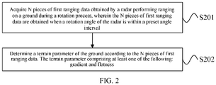
- FIG. 2 is a flowchart of a terrain prediction method according to one embodiment of the present disclosure. As shown in FIG. 2 , the method in this embodiment may include the following.
- N pieces of first ranging data obtained by a radar performing ranging on a ground during a rotation process are acquired, where the N pieces of first ranging data are obtained when a rotation angle of the radar is within a preset angle interval.
- a terrain parameter of the ground is determined according to the N pieces of first ranging data, where the terrain parameter includes at least one of the following: gradient and flatness.
- the ground can be measured by a radar to obtain the distance between the radar and the ground.
- the radar can rotate.
- the ranging point of the radar to measure the ground is also different, and hence the distance to the ground detected by the radar may also be different, as shown in FIG. 3 .
- This embodiment acquires the multiple pieces of first ranging data obtained by the radar when measuring the ground while rotating with a rotation angle being within a preset angle interval.
- the number of pieces of first ranging data is counted as N that is an integer greater than or equal to 2.
- Each piece of first ranging data reflects the distance of the radar from the ground when it is rotated to the corresponding rotation angle.
- the ground where the ranging point is at is high, the distance between the radar and the ground is small, and if the ground where the ranging point is at is low, the distance between the radar and the ground is large. Specifically, if a ground is high in one area and low in another area, a low flatness of the ground is indicated. For the same plurality of ranging points, if the distances between the radar and the ground are all small, it is indicated that the gradient of the ground where the plurality of ranging points are located is high. On the other hand, if the distances between the radar and the ground are large, the gradient of the ground where the plurality of ranging points are located is low. Since the ground is a surface and a plurality of points can determine a surface, this embodiment can determine the terrain parameters of a ground according to the multiple pieces of first ranging data obtained from the plurality of ranging points. The terrain parameters include gradient, flatness of the ground.
- the preset angle interval is 60 degrees to 120 degrees
- the corresponding terrain parameters of the ground directly below the radar can be determined.
- the preset angle interval is -30 degrees to 30 degrees
- the corresponding terrain parameters of the ground in front of the radar can be determined.
- the preset angle range is 150 degrees to 210 degrees
- the corresponding terrain parameters of the ground behind the radar can be determined.
- the preset angel interval can be set according to actual needs. If the preset angle interval of this embodiment is 60 degrees to 120 degrees, the first ranging data can be obtained by the radar ranging from the ground at a rotation angle of 60 degrees, 60.6 degrees, 61.2 degrees, 61.8 degrees, and so on, which will not be repeated here.
- a terrain parameter of the ground such as gradient and integrity, etc. is determined according to the multiple pieces of first ranging data obtained by ranging the ground when within a preset angle interval while rotating. Since each piece of first ranging data reflects the distance between the radar and the ground ranging point when the radar is rotated to the corresponding rotation angle, the multiple pieces of first ranging data can reflect the terrain change of the ground, and hence the gradient and integrity, etc. can be predicted accordingly.
- the ranging data is obtained by the radar, and the radar is not required to directly contact the ground, thereby avoiding the noise interference caused by the direct contact and achieving higher accuracy of the ground terrain prediction.
- Each piece of first ranging data includes the horizontal distance of the radar from the ground ranging point, and the vertical distance of the radar from the ground ranging point. Since the rotation angle of the radar is different, the signal transmission direction of the radar is different, resulting in different ground ranging points, and hence the ground ranging point varies with the rotation angle of the radar. In this embodiment, in order to avoid the situation that the distance between the radar and the ground ranging point is same while the terrain of the ground is different, which causes subsequent inaccurate terrain predictions, the first ranging data includes the above-mentioned horizontal distance and vertical distance that can be obtained according to the distance between the radar and the ground ranging point and the rotation angle of the radar corresponding to the ground ranging point.
- the radar has a larger horizontal distance from the ground ranging point and a small vertical distance, it can be considered that the gradient of the ground is higher.
- the radar has a smaller horizontal distance from the ground ranging point and a large vertical distance, it can be considered that the gradient of the ground is lower.
- a possible implementation method of above described S201 may include the following steps A and B:
- M pieces of second ranging data obtained by a radar performing ranging on a ground during a rotation process are acquired, where the M pieces of second ranging data are all the ranging data obtained when the radar is performing ranging on the ground with a rotation angle in a preset angle interval, and M is an integer greater than or equal to N.
- ranging data obtained by the radar when the rotation angle of the radar is within a preset angle interval during rotation are acquired. These ranging data are referred to as M pieces of second ranging data and M is an integer greater than or equal to N.
- a possible implementation method of step A may include steps A1 and A2.
- step A1 all the second ranging data of the ground ranging for one revolution of the radar and the rotation angle of the radar corresponding to each piece of second ranging data are obtained.
- the second ranging data corresponding to the rotation angles of the radar located in the preset angle interval according to the preset angle interval are obtained and determined as the M pieces of second ranging data.
- one revolution of the radar corresponds to a rotation of the radar by a total of 360 degrees. For example, if one revolution of the radar corresponds to 600 light grids, every time the radar rotates for 0.6 degree indicates that the radar rotates to a corresponding light grid, and then a range measurement is triggered, and hence 600 pieces of ranging data can be obtained.
- this embodiment also records the rotation angle of the radar corresponding to each piece of ranging data. The ranging principle of a radar can be obtained by referring to the related description in the existing technologies, which will not be repeated here. Then the second ranging data corresponding to the rotation angle of the radar located in the preset angle interval according to the preset angle interval are obtained.
- the second ranging data corresponding to 60, 60.6, 61.2, ..., 118.8, 119.4, and 120 degrees can be filtered out and hence a total of 100 pieces of second ranging data can be obtained, that is, M is equal to 100.
- N pieces of first ranging data are acquired according to the M pieces of second ranging data.
- the second ranging data is data obtained by actual ranging of the radar.
- the N pieces of first ranging data used for performing terrain prediction can be obtained according to the M pieces of second ranging data, where N is an integer smaller than or equal to M.
- a possible implementation method of above described step B may include step B1.
- the N pieces of first ranging data are determined according to the M pieces of second ranging data and a valid ranging condition including, smaller than or equal to a preset maximum distance and larger than or equal to a preset minimum distance.
- a valid ranging condition can be set and expressed as [ d min , d max ], that is, a valid second ranging data should be larger than or equal to d min , and smaller than or equal to d max .
- the N pieces of first ranging data determined according to the M pieces of second ranging data and the valid ranging condition are used to predict the terrain of the ground and errors of the ranging data are avoided to improve the accuracy of the terrain prediction.
- a possible implementation method of above described step B1 may include steps B11 and B12.
- the second ranging data satisfying the described valid ranging condition are determined as N pieces of second ranging data from the described M pieces of second ranging data.
- all the second ranging data smaller than or equal to a preset maximum distance and smaller than or equal to a preset minimum distance are determined from the M pieces of second ranging data as the N pieces of second ranging data.
- the N pieces of first ranging data are determined according to the N pieces of second ranging data.
- the N pieces of first ranging data are determined according to the N pieces of second ranging data that meet the valid ranging condition determined above.
- the N pieces of second ranging data may be determined as the N pieces of first ranging data, that is, the first ranging data is equal to the second ranging data.
- the N pieces of first ranging data are obtained by smoothing the N pieces of second ranging data.
- the N pieces of second ranging data are sorted according to an order of the rotation angles of the radar corresponding to the second ranging data.
- the first piece of second ranging data is the second ranging data d 1 corresponding to 60 degrees
- the second piece of second ranging data is the second ranging data d 2 corresponding to 60.6 degrees
- the first piece of second ranging data is the first piece of first ranging data, that is, D 1 is equal to d 1
- the Nth piece of second ranging data is the Nth piece of second ranging data, that is, D N is equal to d N .
- D j is not limited to the average value of the three of d j and its adjacent left one and right one, and may also be the average value of d j and its adjacent left two and right two.
- the first and second piece of first ranging data are respectively equal to the first and second piece of second ranging data
- the (N-1)th and Nth piece of first ranging data are respectively equal to the (N-1)th and Nth piece of second ranging data.
- adjacent three, four, and so on can also be used for smoothing with similar method, and will not be repeated here.
- the above d j can be one value, that is, the distance between the radar and the ground ranging point.
- the horizontal distance x j and the vertical distance y j in the corresponding first ranging data are obtained according to the corresponding rotation angle of the radar.
- the above d j can include two values, that is, the horizontal distance and the vertical distance between the radar and the ground ranging point.
- the horizontal distance can be smoothed to obtain the horizontal distance in the first ranging data
- the vertical distance can be smoothed to obtain the vertical distance in the first ranging data.
- a possible implementation method of above described S202 may include the following steps C and D:
- a linear fitting is performed on the N pieces of first ranging data by a least square method to obtain a linear function.
- the slope and intercept in the linear function are determined according to the N pieces of first ranging data, the linear function, and a least square method.
- the N pieces of first ranging data are known, and each piece of first ranging data includes the horizontal distance and the vertical distance between the radar and the corresponding ground ranging point.
- the slope (e.g., a) and the intercept (e.g., b) of the linear function are determined by substituting the known values of the N groups of x and y into the above Equation 1, and then using the least square method.
- this embodiment is not limited to the above described least square method, and a filtering method can also be adopted.
- step D terrain parameters of the ground are determined according to the linear function.
- the gradient of the ground can be determined according to the slope of the linear function.
- the larger the slope of the linear function, the larger the gradient of the ground, and the smaller the slope of the linear function, the smaller the gradient of the ground; and/or, the flatness of the ground can be determined according to the slope and the intercept of the linear function.
- the following describes how to determine the slope and the intercept in a linear function according to the N pieces of first ranging data, the linear function, and the least square method.
- the value of the slope and the value of the intercept of the linear function are determined according to the weighted sum of squared residuals. Specifically, the value of the slope and the value of the intercept of the linear function are determined based on that the first derivative of the weighted sum of squared residuals to the slope is equal to a first preset value and the first derivative of the weighted sum of squared residuals to the intercept is equal to a second preset value.
- the first preset value and the second preset value can be set to 0 in order to minimize the value of Q and optimize the values of a and b. Accordingly, the first derivative of the weighted sum of squared residuals (Q) to the slope (a) is equal to 0, and the first derivative of the weighted sum of squared residuals (Q) to the intercept (b) is equal to 0.
- â can be used as the value of the slope a
- b ⁇ can be used as the value of the intercept b.
- a possible implementation method for determining the flatness of the ground is, determining the value of the weighted sum of squared residuals based on the value of the determined slope and the value of the determined intercept.
- the value of Q is obtained by substituting the value of a (above â ) and the value of b (above b ⁇ ) into the above Equation 2.
- the flatness of the ground can be determined according to the value of the weighted sum of squared residuals. For example, the larger the value of Q, the more uneven the ground, and the smaller the value of Q, the more flat the ground.
- Equations 4 and 2 as described above can be stored in advance.
- â and b ⁇ can be obtained by substituting the obtained N pieces of first ranging data into the pre-stored Equation 4.
- the gradient of the ground can be determined according to â.
- Q can be obtained by substituting the obtained â and b ⁇ into the pre-stored Equation 2.
- the flatness of the ground can be determined according to the value of Q.
- the weighting coefficients of the residuals corresponding to all of the first ranging data are equal, in which case even if the values of i are different, w i is the same. For example, all w i are equal to 1, or all w i are equal to 1/N, which indicates the sum of the weighting coefficients of the residuals corresponding to the N pieces of first ranging data is equal to 1.
- the ranging data obtained through radar ranging since the ranging data obtained through radar ranging has an error that increases as distance increases, it is needed to assign a weight to the corresponding first ranging data according to the radar rotation angle.
- the shape of the above function can be adjusted according to the value of the variance.
- the smaller the variance the larger the weight of the median of the preset angle interval.
- the larger the variance the smaller the weight of the median of the preset angle interval.
- the value of the variance can be set in advance according to the actual needs. If the preset angle interval is 60-120 degrees, ⁇ is 90 degrees.
- the flatness can be used in the height determination and obstacle avoidance scheme of an unmanned aerial vehicle.
- the slope can be used to guide the subsequent actions of an unmanned aerial vehicle.
- the radar in the above embodiments may be an electromagnetic wave radar, or may be a lidar.
- An embodiment of the present disclosure also provides a computer storage medium storing program instructions, and the execution of the program may implement a part or all of the steps of the terrain prediction method shown in FIG. 2 and its corresponding embodiments.
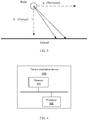
- FIG. 4 is a schematic structural diagram of a terrain prediction device according to one embodiment of the present disclosure.
- the terrain prediction device 400 in this embodiment may include a memory 401 and processor 402 that are connected to each other through a bus.
- the memory 401 may include a read-only memory and a random access memory, and provide instructions and data to the processor 402.
- a part of the memory 401 may further include a non-volatile random access memory.
- the memory 401 is used to store a computer program.
- the processor 402 is used to call and execute the computer program to perform the following operations: acquiring N pieces of first ranging data obtained by a radar performing ranging on a ground during a rotation process, where the N pieces of first ranging data are obtained when a rotation angle of the radar is within a preset angle interval and N is an integer greater than 1, and determining a terrain parameter of the ground according to the N pieces of first ranging data, where the terrain parameter includes at least one of the following: gradient and flatness.
- the first ranging data includes the horizontal distance and the vertical distance of the radar from the ground ranging point, where the ground ranging point varies with the rotation angle of the radar.
- the processor 402 is specifically used for performing a linear fitting on the N pieces of first ranging data by a least square method to obtain a linear function; and determining terrain parameters of the ground according to the linear function.
- the processor 402 is specifically used for constructing a linear function of the vertical distance between the radar and the ground ranging point and the horizontal distance between the radar and the ground ranging point; determining the slope and intercept in the linear function according to the N pieces of first ranging data, the linear function, and a least square method; and determining the gradient of the ground according to the slope of the linear function, and/or, determining the flatness of the ground according to the slope and the intercept of the linear function.
- the processor 402 when the slope and the intercept in a linear function are determined according to the N pieces of first ranging data, the linear function, and the least square method, the processor 402 is specifically used for determining a residual in the linear function corresponding to each piece of first ranging data according to the N pieces of first ranging data and the linear function, where the residual corresponding to each piece of first ranging data is a function of the slope and the intercept of the linear function; determining a weighted sum of squared residuals corresponding to the N pieces of ranging data according to the residuals corresponding to various pieces of first ranging data and the weighting coefficients of the residuals; and determining the value of the slope and the value of the intercept of the linear function according to the weighted sum of squared residuals.
- the processor 402 is specifically used for determining the value of the weighted sum of squared residuals based on the value of the determined slope and the value of the determined intercept; and determining the flatness of the ground according to the value of the weighted sum of squared residuals.
- the processor 402 is specifically used for determining the value of the slope and the value of the intercept of the linear function based on that the first derivative of the weighted sum of squared residuals to the slope is equal to a first preset value and the first derivative of the weighted sum of squared residuals to the intercept is equal to a second preset value.
- the first preset value and the second preset value are 0.
- the weighting coefficients of the residuals corresponding to all of the first ranging data are equal, or, the weighting coefficient of the residual corresponding to each piece of first ranging data is a trigonometric function or a Gaussian function of the rotation angle of the radar corresponding to the first ranging data.
- the sum of the weighting coefficients of the residuals corresponding to the N pieces of first ranging data is equal to 1.
- the processor 402 is specifically used for acquiring M pieces of second ranging data obtained by a radar performing ranging on a ground during a rotation process, where the M pieces of second ranging data are all the ranging data obtained when the radar is performing ranging on the ground with a rotation angle in a preset angle interval, and M is an integer greater than or equal to N; and acquiring N pieces of first ranging data according to the M pieces of second ranging data.
- the processor 402 is specifically used for determining the N pieces of first ranging data according to the M pieces of second ranging data and a valid ranging condition including, smaller than or equal to a preset maximum distance and larger than or equal to a preset minimum distance.
- the processor 402 is specifically used for determining the second ranging data satisfying the described valid ranging condition as N pieces of second ranging data from the described M pieces of second ranging data; and determining N pieces of first ranging data according to the N pieces of second ranging data.
- the processor 402 is specifically used for determining the N pieces of second ranging data as the N pieces of first ranging data; or, obtaining the N pieces of first ranging data by smoothing the N pieces of second ranging data.
- the processor 402 is specifically used for sorting the N pieces of second ranging data according to an order of the rotation angles of the radar corresponding to the second ranging data; determining that the first piece of second ranging data is the first piece of first ranging data, and the Nth piece of second ranging data is the Nth piece of first ranging data; and determining the average value of the (j-1)th piece of second ranging data, the jth piece of second ranging data, and the (j+1)th piece of second ranging data as the jth piece of first ranging data, where j is an integer larger than or equal to 2 and smaller than or equal to N-1.
- the processor 402 is specifically used for obtaining all the second ranging data of the ground ranging for one revolution of the radar and the rotation angle of the radar corresponding to each piece of second ranging data; and obtaining and determining the second ranging data corresponding to the rotation angle of the radar located in the preset angle interval according to the preset angle interval as the M pieces of second ranging data.
- the above described terrain prediction device 400 can be a radar, or can be an unmanned aerial vehicle, or can be a control terminal of the unmanned aerial vehicle.
- the unmanned aerial vehicle can be an agricultural unmanned aerial vehicle.
- the device in this embodiment can be used to implement the technical solutions of the above described method in the embodiments of the present disclosure.
- the implementation principles and technical effects are similar, and are not repeated here.
- FIG. 5 is a schematic structural diagram of an unmanned aerial vehicle according to one embodiment of the present disclosure.
- the unmanned aerial vehicle 500 in this embodiment includes a radar 501 and a terrain prediction device 502, which are communicatively connected to each other.
- the terrain prediction device 502 may adopt the structure of the embodiment shown in FIG. 4 .
- the terrain prediction device 502 may implement the technical solution shown in FIG. 2 and its corresponding embodiments. The implementation principles and technical effects are similar and will not be repeated here.
- the unmanned aerial vehicle 500 also includes other components that are not shown here.
- FIG. 6 is a schematic structural diagram of a terrain prediction system according to one embodiment of the present disclosure.
- the terrain prediction system 600 in this embodiment includes an unmanned aerial vehicle 601 and a control terminal 602, which are communicatively connected with each other.
- the control terminal 602 is used to control the unmanned aerial vehicle 601.
- the unmanned aerial vehicle 601 is equipped with a radar 601a and the control terminal 602 includes a terrain prediction device 602a.
- the terrain prediction device 602a may adopt the structure of the embodiment shown in FIG. 4 .
- the terrain prediction device 602a may implement the technical solution shown in FIG. 2 and its corresponding embodiments. The implementation principles and technical effects are similar and will not be repeated here.
- the unmanned aerial vehicle 601 and the control terminal 602 also include other components that are not shown here.
- the program can be stored in a computer-readable storage medium.
- the storage medium can be any medium that can store program codes, for example, a read-only memory (ROM), a random access memory (RAM), a magnetic disk, or an optical disk.
Landscapes
- Engineering & Computer Science (AREA)
- Remote Sensing (AREA)
- Radar, Positioning & Navigation (AREA)
- Physics & Mathematics (AREA)
- Aviation & Aerospace Engineering (AREA)
- General Physics & Mathematics (AREA)
- Computer Networks & Wireless Communication (AREA)
- Electromagnetism (AREA)
- Mechanical Engineering (AREA)
- Microelectronics & Electronic Packaging (AREA)
- Radar Systems Or Details Thereof (AREA)
- Image Analysis (AREA)
Abstract
Description
- The present disclosure relates to the unmanned aerial vehicle technology field, and more particularly, to a terrain prediction method, device, and system, and an unmanned aerial vehicle.
- Currently unmanned aerial vehicles can be used in a variety of scenarios. Taking the agricultural industry as an example, unmanned aerial vehicles can cultivate land, sow, spray pesticides, and harvest crops, which brings great benefits to the agricultural sector. In these operating scenarios, most unmanned aerial vehicles need to fly near the ground, and avoid accidentally hitting the ground when climbing uphill. On a relatively flat ground, based on Global Positioning System (GPS) and Inertial Measurement Unit (IMU) data, unmanned aerial vehicles can successfully complete the above tasks. In rough terrain, unmanned aerial vehicles need to adjust their actions in advance, such as climbing, downhill, deceleration, braking, etc., to achieve near-ground flight or even contour flight, making the unmanned aerial vehicle to complete the above operations better. Therefore, unmanned aerial vehicles need to predict the terrain conditions of the ground on which they operate. In the existing technologies, a car is driven through the ground, during the passing process, the relative change of acceleration is generated by the contact between the car and the ground, and then the terrain of the ground is estimated based on the change in acceleration. However, the contact between the car and the ground generates high frequency noise, which affects the amount of change in acceleration, and hence affects the accuracy of terrain prediction.
- In accordance with the present disclosure, there is provided a terrain prediction method, device, and system, and an unmanned aerial vehicle, which are used to improve the accuracy of terrain prediction.
- In a first aspect, an embodiment of the present disclosure provides a terrain prediction method including acquiring N pieces of first ranging data obtained by a radar performing ranging on a ground during a rotation process, where the N pieces of first ranging data are obtained when a rotation angle of the radar is within a preset angle interval and N is an integer greater than 1, and determining a terrain parameter of the ground according to the N pieces of first ranging data, where the terrain parameter includes at least one of the following: gradient and flatness.
- In a second aspect, an embodiment of the present disclosure provides a terrain prediction device including a memory storing a computer program and a processor configured to call and execute the computer program to perform the following operations: acquiring N pieces of first ranging data obtained by a radar performing ranging on a ground during a rotation process, where the N pieces of first ranging data are obtained when a rotation angle of the radar is within a preset angle interval and N is an integer greater than 1, and determining a terrain parameter of the ground according to the N pieces of first ranging data, where the terrain parameter includes at least one of the following: gradient and flatness.
- In a third aspect, an embodiment of the present disclosure provides an unmanned aerial vehicle including a radar and a terrain prediction device, where the terrain prediction device is communicatively connected to the radar. The terrain prediction device is the terrain prediction device according to the embodiment of the present disclosure in the second aspect.
- In a fourth aspect, an embodiment of the present disclosure provides a terrain prediction system including an unmanned aerial vehicle and a control terminal, where the unmanned aerial vehicle is communicatively connected to the control terminal. The control terminal is configured to control the unmanned aerial vehicle. The unmanned aerial vehicle is equipped with a radar. The control terminal includes the terrain prediction device according to the embodiment of the present disclosure in the second aspect.
- In a fifth aspect, an embodiment of the present disclosure provides a chip including a memory storing a computer program and a processor configured to call and execute the computer program to perform the following operations: acquiring N pieces of first ranging data obtained by a radar performing ranging on a ground during a rotation process, where the N pieces of first ranging data are obtained when a rotation angle of the radar is within a preset angle interval and N is an integer greater than 1, and determining a terrain parameter of the ground according to the N pieces of first ranging data, where the terrain parameter includes at least one of the following: gradient and flatness.
- In a sixth aspect, an embodiment of the present disclosure provides a readable storage medium storing a computer program. When the computer program is executed, the terrain prediction method according to the embodiment of the present disclosure is implemented.
- The terrain prediction method, device and system, and unmanned aerial vehicle provided by the embodiments of the present disclosure determine a terrain parameter of the ground such as gradient and integrity, etc., according to multiple pieces of first ranging data obtained by measuring the ground in a range of rotation to a preset angle interval during rotation. Since each piece of first ranging data reflects the distance between the radar and the ground ranging point when the radar is rotated to the corresponding rotation angle, the multiple pieces of first ranging data can reflect the terrain change of the ground, and hence the gradient and integrity, etc. can be predicted accordingly. In this embodiment, the ranging data is obtained by the radar, and does not require the radar to directly contact the ground, thereby avoiding the noise interference caused by the direct contact and achieving higher accuracy of the ground terrain prediction.
- In order to more clearly explain the embodiments of the present disclosure or the technical solutions in the existing technologies, the drawings used in the description of the embodiments or the existing technologies will be briefly introduced below. Obviously, the drawings in the following description are some embodiments of the present disclosure. For those of ordinary skill in the art, other drawings can be obtained based on these drawings without creative efforts.
-
FIG. 1 is a schematic structural diagram of an agricultural unmannedaerial vehicle 100 according to one embodiment of the present disclosure. -
FIG. 2 is a flowchart of a terrain prediction method according to one embodiment of the present disclosure. -
FIG. 3 is a schematic diagram of radar ranging according to one embodiment of the present disclosure. -
FIG. 4 is a schematic structural diagram of a terrain prediction device according to one embodiment of the present disclosure. -
FIG. 5 is a schematic structural diagram of an unmanned aerial vehicle according to one embodiment of the present disclosure. -
FIG. 6 is a schematic structural diagram of a terrain prediction system according to one embodiment of the present disclosure. - To better illustrate the objectives, technical solutions, and advantages of embodiments of the present disclosure, technical solutions of the present disclosure will be described with reference to the drawings. It will be appreciated that the described embodiments are some rather than all of the embodiments of the present disclosure. Other embodiments conceived by those having ordinary skills in the art on the basis of the described embodiments without inventive efforts should fall within the scope of the present disclosure.
- Embodiments of the present disclosure provide a terrain prediction method, device, and system, and an unmanned aerial vehicle. The unmanned aerial vehicle can be an agricultural unmanned aerial vehicle, such as a rotorcraft, e.g., a multi-rotor aircraft propelled by a plurality of propulsion devices through air, and embodiments of the present disclosure are not limited to these terms.
-
FIG. 1 is a schematic structural diagram of an agricultural unmannedaerial vehicle 100 according to one embodiment of the present disclosure. This embodiment is described by taking a rotary wing unmanned aerial vehicle (UAV) as an example. - An agricultural unmanned
aerial vehicle 100 may include a power system, a flight control system, and a rack. The agricultural unmannedaerial vehicle 100 can wirelessly communicate with a control terminal that can display flight information of the agricultural unmanned aerial vehicle, etc. The control terminal may communicate with the agricultural unmannedaerial vehicle 100 in a wireless manner for remotely controlling the agricultural unmannedaerial vehicle 100. - A rack may include a
vehicle body 110 and a stand 120 (also referred to as a landing gear). Thevehicle body 110 may include acenter frame 111 and one ormore arms 112 connected to thecenter frame 111. The one ormore arms 112 extend radially from the center frame. Thestand 120 is connected to thevehicle body 110, and is used for supporting the agricultural unmannedaerial vehicle 100 during landing. Aliquid storage tank 130 used to store chemical liquid or water is mounted between thestands 120. Aspray head 140 is mounted at the end of thearm 112, and the liquid in theliquid storage tank 130 is pumped into thespray head 140 through a pump, and is sprayed out by thespray head 140. - The power system may include one or more electronic speed controllers (simply referred to as ESCs), one or
more propellers 150, and one ormore motors 160 corresponding to the one ormore propellers 150. Themotor 160 is connected between the electronic speed controller and thepropeller 150. Themotor 160 and thepropeller 150 are configured on thearm 112 of the agricultural unmannedaerial vehicle 100. The electronic speed controller is used to receive the driving signal generated by the flight control system and provide a driving current to the motor according to the driving signal to control the rotation speed of themotor 160. Themotor 160 is used to drive thepropeller 150 to rotate, thereby providing power for the flight of the agricultural unmannedaerial vehicle 100, and the power enables the agricultural unmannedaerial vehicle 100 to perform movements with one or more degrees of freedom. In some embodiments, the agricultural unmannedaerial vehicle 100 may rotate around one or more rotation axis. For example, the rotation axis may include a roll axis, a yaw axis, and a pitch axis. It should be understood that themotor 160 can be a DC motor or an AC motor, a brushless motor or a brushed motor. - The flight control system can include a flight controller and a sensing system. The sensing system is used to measure the attitude information of the unmanned aerial vehicle, that is, the position information and status information of the agricultural unmanned
aerial vehicle 100 in space, such as three-dimensional position, three-dimensional angle, three-dimensional velocity, three-dimensional acceleration, and three-dimensional angular velocity, etc. The sensing system may include, for example, at least one of a gyroscope, an ultrasonic sensor, an electronic compass, an inertial measurement unit (IMU), a vision sensor, a global navigation satellite system, and a barometer, etc. For example, a global navigation satellite system may be a Global Positioning System (GPS). The flight controller is used to control the flight of the agricultural unmannedaerial vehicle 100. For example, the flight controller can control the flight of the agricultural unmannedaerial vehicle 100 according to the attitude information measured by the sensing system. It should be understood that the flight controller may control the agricultural unmannedaerial vehicle 100 according to a pre-programmed program instruction, and may also control the agricultural unmannedaerial vehicle 100 by responding to one or more control instructions from the control terminal. - As shown in
FIG. 1 , astand 120 of an agricultural unmanned aerial vehicle can also be equipped with aradar 170 that is a rotary radar. Theradar 170 can be used for but not limited to ranging. - It should be understood that the above described naming of various components of the agricultural unmanned aerial vehicle is for identification purposes only, and should not be construed as limiting the embodiments of the present disclosure.
-
FIG. 2 is a flowchart of a terrain prediction method according to one embodiment of the present disclosure. As shown inFIG. 2 , the method in this embodiment may include the following. - At S201, N pieces of first ranging data obtained by a radar performing ranging on a ground during a rotation process are acquired, where the N pieces of first ranging data are obtained when a rotation angle of the radar is within a preset angle interval.
- At S202, a terrain parameter of the ground is determined according to the N pieces of first ranging data, where the terrain parameter includes at least one of the following: gradient and flatness.
- In this embodiment, the ground can be measured by a radar to obtain the distance between the radar and the ground. The radar can rotate. When the radar rotates at different angles, the ranging point of the radar to measure the ground is also different, and hence the distance to the ground detected by the radar may also be different, as shown in
FIG. 3 . This embodiment acquires the multiple pieces of first ranging data obtained by the radar when measuring the ground while rotating with a rotation angle being within a preset angle interval. The number of pieces of first ranging data is counted as N that is an integer greater than or equal to 2. Each piece of first ranging data reflects the distance of the radar from the ground when it is rotated to the corresponding rotation angle. For a same ranging point, if the ground where the ranging point is at is high, the distance between the radar and the ground is small, and if the ground where the ranging point is at is low, the distance between the radar and the ground is large. Specifically, if a ground is high in one area and low in another area, a low flatness of the ground is indicated. For the same plurality of ranging points, if the distances between the radar and the ground are all small, it is indicated that the gradient of the ground where the plurality of ranging points are located is high. On the other hand, if the distances between the radar and the ground are large, the gradient of the ground where the plurality of ranging points are located is low. Since the ground is a surface and a plurality of points can determine a surface, this embodiment can determine the terrain parameters of a ground according to the multiple pieces of first ranging data obtained from the plurality of ranging points. The terrain parameters include gradient, flatness of the ground. - For example, when the preset angle interval is 60 degrees to 120 degrees, the corresponding terrain parameters of the ground directly below the radar can be determined. When the preset angle interval is -30 degrees to 30 degrees, the corresponding terrain parameters of the ground in front of the radar can be determined. When the preset angle range is 150 degrees to 210 degrees, the corresponding terrain parameters of the ground behind the radar can be determined. It should be noted that the above described examples are for the purpose of illustration and are not limiting. The preset angel interval can be set according to actual needs. If the preset angle interval of this embodiment is 60 degrees to 120 degrees, the first ranging data can be obtained by the radar ranging from the ground at a rotation angle of 60 degrees, 60.6 degrees, 61.2 degrees, 61.8 degrees, and so on, which will not be repeated here.
- In this embodiment, a terrain parameter of the ground, such as gradient and integrity, etc. is determined according to the multiple pieces of first ranging data obtained by ranging the ground when within a preset angle interval while rotating. Since each piece of first ranging data reflects the distance between the radar and the ground ranging point when the radar is rotated to the corresponding rotation angle, the multiple pieces of first ranging data can reflect the terrain change of the ground, and hence the gradient and integrity, etc. can be predicted accordingly. In this embodiment, the ranging data is obtained by the radar, and the radar is not required to directly contact the ground, thereby avoiding the noise interference caused by the direct contact and achieving higher accuracy of the ground terrain prediction.
- Each piece of first ranging data includes the horizontal distance of the radar from the ground ranging point, and the vertical distance of the radar from the ground ranging point. Since the rotation angle of the radar is different, the signal transmission direction of the radar is different, resulting in different ground ranging points, and hence the ground ranging point varies with the rotation angle of the radar. In this embodiment, in order to avoid the situation that the distance between the radar and the ground ranging point is same while the terrain of the ground is different, which causes subsequent inaccurate terrain predictions, the first ranging data includes the above-mentioned horizontal distance and vertical distance that can be obtained according to the distance between the radar and the ground ranging point and the rotation angle of the radar corresponding to the ground ranging point. Specifically, for the same distance between the radar and the ground ranging point, if the radar has a larger horizontal distance from the ground ranging point and a small vertical distance, it can be considered that the gradient of the ground is higher. On the other hand, if the radar has a smaller horizontal distance from the ground ranging point and a large vertical distance, it can be considered that the gradient of the ground is lower.
- In some embodiments, a possible implementation method of above described S201 may include the following steps A and B:
- At step A, M pieces of second ranging data obtained by a radar performing ranging on a ground during a rotation process are acquired, where the M pieces of second ranging data are all the ranging data obtained when the radar is performing ranging on the ground with a rotation angle in a preset angle interval, and M is an integer greater than or equal to N.
- In this embodiment, all the ranging data obtained by the radar when the rotation angle of the radar is within a preset angle interval during rotation are acquired. These ranging data are referred to as M pieces of second ranging data and M is an integer greater than or equal to N.
- In some embodiments, a possible implementation method of step A may include steps A1 and A2.
- At step A1, all the second ranging data of the ground ranging for one revolution of the radar and the rotation angle of the radar corresponding to each piece of second ranging data are obtained.
- At step A2, the second ranging data corresponding to the rotation angles of the radar located in the preset angle interval according to the preset angle interval are obtained and determined as the M pieces of second ranging data.
- In this embodiment, one revolution of the radar corresponds to a rotation of the radar by a total of 360 degrees. For example, if one revolution of the radar corresponds to 600 light grids, every time the radar rotates for 0.6 degree indicates that the radar rotates to a corresponding light grid, and then a range measurement is triggered, and hence 600 pieces of ranging data can be obtained. In addition, this embodiment also records the rotation angle of the radar corresponding to each piece of ranging data. The ranging principle of a radar can be obtained by referring to the related description in the existing technologies, which will not be repeated here. Then the second ranging data corresponding to the rotation angle of the radar located in the preset angle interval according to the preset angle interval are obtained. For example, if the preset angle interval is 60-120 degrees, the second ranging data corresponding to 60, 60.6, 61.2, ..., 118.8, 119.4, and 120 degrees can be filtered out and hence a total of 100 pieces of second ranging data can be obtained, that is, M is equal to 100.
- At step B, N pieces of first ranging data are acquired according to the M pieces of second ranging data.
- In this embodiment, the second ranging data is data obtained by actual ranging of the radar. After the above described M pieces of second ranging data are obtained, the N pieces of first ranging data used for performing terrain prediction can be obtained according to the M pieces of second ranging data, where N is an integer smaller than or equal to M.
- In some embodiments, a possible implementation method of above described step B may include step B1.
- At step B1, the N pieces of first ranging data are determined according to the M pieces of second ranging data and a valid ranging condition including, smaller than or equal to a preset maximum distance and larger than or equal to a preset minimum distance.
- In this embodiment, the validity of each piece of ranging data is judged. A radar has a dead zone in a short range and a longest ranging distance. Therefore, a valid ranging condition can be set and expressed as [dmin, dmax ], that is, a valid second ranging data should be larger than or equal to dmin, and smaller than or equal to dmax. In this embodiment, the N pieces of first ranging data determined according to the M pieces of second ranging data and the valid ranging condition are used to predict the terrain of the ground and errors of the ranging data are avoided to improve the accuracy of the terrain prediction.
- In some embodiments, a possible implementation method of above described step B1 may include steps B11 and B12.
- At step B11, the second ranging data satisfying the described valid ranging condition are determined as N pieces of second ranging data from the described M pieces of second ranging data.
- In this embodiment, all the second ranging data smaller than or equal to a preset maximum distance and smaller than or equal to a preset minimum distance are determined from the M pieces of second ranging data as the N pieces of second ranging data.
- At step B11, the N pieces of first ranging data are determined according to the N pieces of second ranging data.
- In this embodiment, the N pieces of first ranging data are determined according to the N pieces of second ranging data that meet the valid ranging condition determined above.
- In a possible implementation method, the N pieces of second ranging data may be determined as the N pieces of first ranging data, that is, the first ranging data is equal to the second ranging data.
- In another possible implementation method, the N pieces of first ranging data are obtained by smoothing the N pieces of second ranging data. For example, the N pieces of second ranging data are sorted according to an order of the rotation angles of the radar corresponding to the second ranging data. For example, the first piece of second ranging data is the second ranging data d1 corresponding to 60 degrees, the second piece of second ranging data is the second ranging data d2 corresponding to 60.6 degrees, and so on. Then it is determined that the first piece of second ranging data is the first piece of first ranging data, that is, D1 is equal to d1, and the Nth piece of second ranging data is the Nth piece of second ranging data, that is, DN is equal to dN. The average value of the (j-1)th piece of second ranging data (i.e., dj-1), the jth piece of second ranging data (i.e., dj), and the (j+1)th piece of second ranging data (i.e., dj+1) is then determined as the jth piece of first ranging data, that is, Dj=[dj-1+dj+dj+1]/3, where j is an integer larger than or equal to 2 and smaller than or equal to N-1.
- It should be noted that Dj is not limited to the average value of the three of dj and its adjacent left one and right one, and may also be the average value of dj and its adjacent left two and right two. Correspondingly, the first and second piece of first ranging data are respectively equal to the first and second piece of second ranging data, and the (N-1)th and Nth piece of first ranging data are respectively equal to the (N-1)th and Nth piece of second ranging data. In this embodiment, adjacent three, four, and so on can also be used for smoothing with similar method, and will not be repeated here.
- Further, the above dj can be one value, that is, the distance between the radar and the ground ranging point. In this embodiment, after the smoothing process is performed, the horizontal distance xj and the vertical distance yj in the corresponding first ranging data are obtained according to the corresponding rotation angle of the radar.
- Further, the above dj can include two values, that is, the horizontal distance and the vertical distance between the radar and the ground ranging point. In this embodiment, the horizontal distance can be smoothed to obtain the horizontal distance in the first ranging data, or the vertical distance can be smoothed to obtain the vertical distance in the first ranging data.
- In some embodiments, a possible implementation method of above described S202 may include the following steps C and D:
- At step C, a linear fitting is performed on the N pieces of first ranging data by a least square method to obtain a linear function.
- Specifically, a linear function of the vertical distance between the radar and the ground ranging point and the horizontal distance between the radar and the ground ranging point is constructed, and can be expressed as shown in Equation 1 for example: y=ax+b+e, where y is the vertical distance between the radar and the ground ranging point, x is the horizontal distance between the radar and the ground ranging point, and a, b, and c are unknown at this time. Then the slope and intercept in the linear function are determined according to the N pieces of first ranging data, the linear function, and a least square method. The N pieces of first ranging data are known, and each piece of first ranging data includes the horizontal distance and the vertical distance between the radar and the corresponding ground ranging point. The slope (e.g., a) and the intercept (e.g., b) of the linear function are determined by substituting the known values of the N groups of x and y into the above Equation 1, and then using the least square method.
- It should be noted that this embodiment is not limited to the above described least square method, and a filtering method can also be adopted.
- At step D, terrain parameters of the ground are determined according to the linear function.
- In this embodiment, the gradient of the ground can be determined according to the slope of the linear function. For example, the larger the slope of the linear function, the larger the gradient of the ground, and the smaller the slope of the linear function, the smaller the gradient of the ground; and/or, the flatness of the ground can be determined according to the slope and the intercept of the linear function.
- The following describes how to determine the slope and the intercept in a linear function according to the N pieces of first ranging data, the linear function, and the least square method.
- In a possible implementation method, a residual in the linear function corresponding to each piece of first ranging data is determined according to the N pieces of first ranging data and the linear function, where the residual corresponding to each piece of first ranging data is a function of the slope and the intercept of the linear function. For example, e=yi-axi-b, where yi is the vertical distance in the ith first ranging data, and xi is the horizontal distance in the ith first ranging data. Then a weighted sum of squared residuals corresponding to the N pieces of ranging data is determined according to the residuals corresponding to various pieces of first ranging data and the weighting coefficients of the residuals. The weighted sum of squared residuals is, for example, expressed as shown in Equation 2:

- In this embodiment, the value of the slope and the value of the intercept of the linear function are determined according to the weighted sum of squared residuals. Specifically, the value of the slope and the value of the intercept of the linear function are determined based on that the first derivative of the weighted sum of squared residuals to the slope is equal to a first preset value and the first derivative of the weighted sum of squared residuals to the intercept is equal to a second preset value.
- The first preset value and the second preset value can be set to 0 in order to minimize the value of Q and optimize the values of a and b. Accordingly, the first derivative of the weighted sum of squared residuals (Q) to the slope (a) is equal to 0, and the first derivative of the weighted sum of squared residuals (Q) to the intercept (b) is equal to 0. This can be shown, for example, in Equation 3:


- According to the above Equation 3, the estimated value â of a and the estimated value b̂ of b can be obtained as shown in Equation 4 below:


- In this embodiment, â can be used as the value of the slope a, and b̂ can be used as the value of the intercept b.
- Correspondingly, according to the slope and intercept of the linear function, a possible implementation method for determining the flatness of the ground is, determining the value of the weighted sum of squared residuals based on the value of the determined slope and the value of the determined intercept. For example, the value of Q is obtained by substituting the value of a (above â) and the value of b (above b̂) into the above Equation 2. Then the flatness of the ground can be determined according to the value of the weighted sum of squared residuals. For example, the larger the value of Q, the more uneven the ground, and the smaller the value of Q, the more flat the ground.
- In an alternative solution, in this embodiment, Equations 4 and 2 as described above can be stored in advance. â and b̂ can be obtained by substituting the obtained N pieces of first ranging data into the pre-stored Equation 4. The gradient of the ground can be determined according to â. Then Q can be obtained by substituting the obtained â and b̂ into the pre-stored Equation 2. The flatness of the ground can be determined according to the value of Q.
- In some embodiments, the weighting coefficients of the residuals corresponding to all of the first ranging data are equal, in which case even if the values of i are different, wi is the same. For example, all wi are equal to 1, or all wi are equal to 1/N, which indicates the sum of the weighting coefficients of the residuals corresponding to the N pieces of first ranging data is equal to 1.
- In some embodiments, since the ranging data obtained through radar ranging has an error that increases as distance increases, it is needed to assign a weight to the corresponding first ranging data according to the radar rotation angle.
- In a possible implementation method, the weighting coefficient of the residual corresponding to each piece of first ranging data is a trigonometric function of the rotation angle of the radar corresponding to the first ranging data, for example, as shown in Equation 5:

- Optionally, if the sum of the weighting coefficients of the residuals corresponding to the N pieces of first ranging data is equal to 1, the above described trigonometric function needs to be normalized. The weighting coefficient of the residual is, for example, as shown in Equation 6:

- In another possible implementation method, the weighting coefficient of the residual corresponding to each piece of first ranging data is a Gaussian function of the rotation angle of the radar corresponding to the first ranging data, for example, as shown in Equation 7:

- The shape of the above function can be adjusted according to the value of the variance. The smaller the variance, the larger the weight of the median of the preset angle interval. The larger the variance, the smaller the weight of the median of the preset angle interval. The value of the variance can be set in advance according to the actual needs. If the preset angle interval is 60-120 degrees, µ is 90 degrees.
- Optionally, if the sum of the weighting coefficients of the residuals corresponding to the N pieces of first ranging data is equal to 1, the above described Gaussian function needs to be normalized. The weighting coefficient of the residual is, for example, as shown in Equation 8:

- In this embodiment, after a flatness of the ground is determined, the flatness can be used in the height determination and obstacle avoidance scheme of an unmanned aerial vehicle. After a gradient of the ground is determined, the slope can be used to guide the subsequent actions of an unmanned aerial vehicle.
- Optionally, the radar in the above embodiments may be an electromagnetic wave radar, or may be a lidar.
- An embodiment of the present disclosure also provides a computer storage medium storing program instructions, and the execution of the program may implement a part or all of the steps of the terrain prediction method shown in
FIG. 2 and its corresponding embodiments. -
FIG. 4 is a schematic structural diagram of a terrain prediction device according to one embodiment of the present disclosure. As shown inFIG. 4 , theterrain prediction device 400 in this embodiment may include amemory 401 andprocessor 402 that are connected to each other through a bus. Thememory 401 may include a read-only memory and a random access memory, and provide instructions and data to theprocessor 402. A part of thememory 401 may further include a non-volatile random access memory. - The
memory 401 is used to store a computer program. - The
processor 402 is used to call and execute the computer program to perform the following operations: acquiring N pieces of first ranging data obtained by a radar performing ranging on a ground during a rotation process, where the N pieces of first ranging data are obtained when a rotation angle of the radar is within a preset angle interval and N is an integer greater than 1, and determining a terrain parameter of the ground according to the N pieces of first ranging data, where the terrain parameter includes at least one of the following: gradient and flatness. - In some embodiments, the first ranging data includes the horizontal distance and the vertical distance of the radar from the ground ranging point, where the ground ranging point varies with the rotation angle of the radar.
- In some embodiments, the
processor 402 is specifically used for performing a linear fitting on the N pieces of first ranging data by a least square method to obtain a linear function; and determining terrain parameters of the ground according to the linear function. - In some embodiments, the
processor 402 is specifically used for constructing a linear function of the vertical distance between the radar and the ground ranging point and the horizontal distance between the radar and the ground ranging point; determining the slope and intercept in the linear function according to the N pieces of first ranging data, the linear function, and a least square method; and determining the gradient of the ground according to the slope of the linear function, and/or, determining the flatness of the ground according to the slope and the intercept of the linear function. - In some embodiments, when the slope and the intercept in a linear function are determined according to the N pieces of first ranging data, the linear function, and the least square method, the
processor 402 is specifically used for determining a residual in the linear function corresponding to each piece of first ranging data according to the N pieces of first ranging data and the linear function, where the residual corresponding to each piece of first ranging data is a function of the slope and the intercept of the linear function; determining a weighted sum of squared residuals corresponding to the N pieces of ranging data according to the residuals corresponding to various pieces of first ranging data and the weighting coefficients of the residuals; and determining the value of the slope and the value of the intercept of the linear function according to the weighted sum of squared residuals. - When the flatness of the ground is determined according to the slope and intercept of the linear function, the
processor 402 is specifically used for determining the value of the weighted sum of squared residuals based on the value of the determined slope and the value of the determined intercept; and determining the flatness of the ground according to the value of the weighted sum of squared residuals. - In some embodiments, the
processor 402 is specifically used for determining the value of the slope and the value of the intercept of the linear function based on that the first derivative of the weighted sum of squared residuals to the slope is equal to a first preset value and the first derivative of the weighted sum of squared residuals to the intercept is equal to a second preset value. - In some embodiments, the first preset value and the second preset value are 0.
- In some embodiments, the weighting coefficients of the residuals corresponding to all of the first ranging data are equal, or, the weighting coefficient of the residual corresponding to each piece of first ranging data is a trigonometric function or a Gaussian function of the rotation angle of the radar corresponding to the first ranging data.
- In some embodiments, the sum of the weighting coefficients of the residuals corresponding to the N pieces of first ranging data is equal to 1.
- In some embodiments, the
processor 402 is specifically used for acquiring M pieces of second ranging data obtained by a radar performing ranging on a ground during a rotation process, where the M pieces of second ranging data are all the ranging data obtained when the radar is performing ranging on the ground with a rotation angle in a preset angle interval, and M is an integer greater than or equal to N; and acquiring N pieces of first ranging data according to the M pieces of second ranging data. - In some embodiments, the
processor 402 is specifically used for determining the N pieces of first ranging data according to the M pieces of second ranging data and a valid ranging condition including, smaller than or equal to a preset maximum distance and larger than or equal to a preset minimum distance. - In some embodiments, the
processor 402 is specifically used for determining the second ranging data satisfying the described valid ranging condition as N pieces of second ranging data from the described M pieces of second ranging data; and determining N pieces of first ranging data according to the N pieces of second ranging data. - In some embodiments, the
processor 402 is specifically used for determining the N pieces of second ranging data as the N pieces of first ranging data; or, obtaining the N pieces of first ranging data by smoothing the N pieces of second ranging data. - In some embodiments, the
processor 402 is specifically used for sorting the N pieces of second ranging data according to an order of the rotation angles of the radar corresponding to the second ranging data; determining that the first piece of second ranging data is the first piece of first ranging data, and the Nth piece of second ranging data is the Nth piece of first ranging data; and determining the average value of the (j-1)th piece of second ranging data, the jth piece of second ranging data, and the (j+1)th piece of second ranging data as the jth piece of first ranging data, where j is an integer larger than or equal to 2 and smaller than or equal to N-1. - In some embodiments, the
processor 402 is specifically used for obtaining all the second ranging data of the ground ranging for one revolution of the radar and the rotation angle of the radar corresponding to each piece of second ranging data; and obtaining and determining the second ranging data corresponding to the rotation angle of the radar located in the preset angle interval according to the preset angle interval as the M pieces of second ranging data. - Optionally, the above described
terrain prediction device 400 can be a radar, or can be an unmanned aerial vehicle, or can be a control terminal of the unmanned aerial vehicle. Optionally, the unmanned aerial vehicle can be an agricultural unmanned aerial vehicle. - The device in this embodiment can be used to implement the technical solutions of the above described method in the embodiments of the present disclosure. The implementation principles and technical effects are similar, and are not repeated here.
-
FIG. 5 is a schematic structural diagram of an unmanned aerial vehicle according to one embodiment of the present disclosure. As shown inFIG. 5 , the unmannedaerial vehicle 500 in this embodiment includes a radar 501 and aterrain prediction device 502, which are communicatively connected to each other. Theterrain prediction device 502 may adopt the structure of the embodiment shown inFIG. 4 . Correspondingly, theterrain prediction device 502 may implement the technical solution shown inFIG. 2 and its corresponding embodiments. The implementation principles and technical effects are similar and will not be repeated here. It should be noted that the unmannedaerial vehicle 500 also includes other components that are not shown here. -
FIG. 6 is a schematic structural diagram of a terrain prediction system according to one embodiment of the present disclosure. As shown inFIG. 6 , theterrain prediction system 600 in this embodiment includes an unmannedaerial vehicle 601 and acontrol terminal 602, which are communicatively connected with each other. Thecontrol terminal 602 is used to control the unmannedaerial vehicle 601. - The unmanned
aerial vehicle 601 is equipped with aradar 601a and thecontrol terminal 602 includes a terrain prediction device 602a. The terrain prediction device 602a may adopt the structure of the embodiment shown inFIG. 4 . Correspondingly, the terrain prediction device 602a may implement the technical solution shown inFIG. 2 and its corresponding embodiments. The implementation principles and technical effects are similar and will not be repeated here. It should be noted that the unmannedaerial vehicle 601 and thecontrol terminal 602 also include other components that are not shown here. - Those having ordinary skills in the art should understand that all or part of the steps of the above described method embodiments can be implemented by a program instruction related hardware. The program can be stored in a computer-readable storage medium. When the program is executed, the program includes steps of the above described method embodiments. The storage medium can be any medium that can store program codes, for example, a read-only memory (ROM), a random access memory (RAM), a magnetic disk, or an optical disk.
- The present disclosure has been described with the above embodiments, but the technical scope of the present disclosure is not limited to the scope described in the above embodiments. Other embodiments of the disclosure will be apparent to those skilled in the art from consideration of the specification and practice of the embodiments disclosed herein. It is intended that the specification and examples be considered as example only and not to limit the scope of the disclosure, with a true scope and spirit of the invention being indicated by the claims.
Claims (33)
- A terrain prediction method, comprising:acquiring N pieces of first ranging data obtained by a radar performing ranging on a ground during rotation, wherein the N pieces of first ranging data are obtained when a rotation angle of the radar is within a preset angle interval and N is an integer greater than 1;determining a terrain parameter of the ground according to the N pieces of first ranging data, wherein the terrain parameter includes at least one of the following: gradient and flatness.
- The method of claim 1, wherein the first ranging data includes a horizontal distance and a vertical distance of the radar from a ground ranging point, wherein the ground ranging point varies with the rotation angle of the radar.
- The method of claim 1 or 2, wherein determining the terrain parameter of the ground according to the N pieces of first ranging data includes:performing a linear fitting on the N pieces of first ranging data by a least square method to obtain a linear function;determining terrain parameters of the ground according to the linear function.
- The method of claim 3, wherein:
performing the linear fitting on the N pieces of first ranging data by the least square method to obtain the linear function includes:constructing the linear function of the vertical distance between the radar and the ground ranging point and the horizontal distance between the radar and the ground ranging point; anddetermining a slope and an intercept in the linear function according to the N pieces of first ranging data, the linear function, and the least square method;determining the terrain parameters of the ground according to the linear function includes:determining the gradient of the ground according to the slope of the linear function; and/ordetermining the flatness of the ground according to the slope and the intercept of the linear function. - The method of claim 4, wherein:determining the slope and the intercept in the linear function according to the N pieces of first ranging data, the linear function, and the least square method includes:determining a residual in the linear function corresponding to each piece of first ranging data according to the N pieces of first ranging data and the linear function, wherein the residual corresponding to each piece of first ranging data is a function of the slope and the intercept of the linear function;determining a weighted sum of squared residuals corresponding to the N pieces of first ranging data according to the residuals corresponding to various pieces of first ranging data and the weighting coefficients of the residuals; anddetermining a value of the slope and a value of the intercept of the linear function according to the weighted sum of squared residuals;determining the flatness of the ground according to the slope and the intercept of the linear function includes:determining a value of the weighted sum of squared residuals based on the value of the slope and the value of the intercept; anddetermining the flatness of the ground according to the value of the weighted sum of squared residuals.
- The method of claim 5, wherein determining the value of the slope and the value of the intercept of the linear function according to the weighted sum of squared residuals includes:
determining the value of the slope and the value of the intercept of the linear function based on that the first derivative of the weighted sum of squared residuals to the slope is equal to a first preset value and the first derivative of the weighted sum of squared residuals to the intercept is equal to a second preset value. - The method of claim 6, wherein the first preset value and the second preset value are 0.
- The method of any of claims 5-7, wherein:weighting coefficients of the residuals corresponding to all of the first ranging data are equal; orthe weighting coefficient of the residual corresponding to each piece of first ranging data is a trigonometric function or a Gaussian function of the rotation angle of the radar corresponding to the first ranging data.
- The method of claim 8, wherein a sum of the weighting coefficients of the residuals corresponding to the N pieces of first ranging data is equal to 1.
- The method of any of claims 1-9, wherein acquiring the N pieces of first ranging data obtained by the radar performing ranging on the ground during rotation includes:acquiring M pieces of second ranging data obtained by the radar performing ranging on the ground during rotation, wherein the M pieces of second ranging data are all the ranging data obtained when the radar is performing ranging on the ground with the rotation angle in the preset angle interval, and M is an integer greater than or equal to N; andacquiring the N pieces of first ranging data according to the M pieces of second ranging data.
- The method of claim 10, wherein acquiring the N pieces of first ranging data according to the M pieces of second ranging data includes:determining the N pieces of first ranging data according to the M pieces of second ranging data and a valid ranging condition;wherein the valid ranging condition includes smaller than or equal to a preset maximum distance and larger than or equal to a preset minimum distance.
- The method of claim 11, wherein determining the N pieces of first ranging data according to the M pieces of second ranging data and the valid ranging condition includes:determining the second ranging data satisfying the valid ranging condition as N pieces of second ranging data from the M pieces of second ranging data; anddetermining the N pieces of first ranging data according to the N pieces of second ranging data.
- The method of claim 12, wherein determining the N pieces of first ranging data according to the N pieces of second ranging data includes:determining the N pieces of second ranging data as the N pieces of first ranging data; orobtaining the N pieces of first ranging data by smoothing the N pieces of second ranging data.
- The method of claim 13, wherein obtaining the N pieces of first ranging data by smoothing the N pieces of second ranging data includes:sorting the N pieces of second ranging data according to an order of the rotation angles of the radar corresponding to the second ranging data;determining that the first piece of second ranging data is the first piece of first ranging data, and the Nth piece of second ranging data is the Nth piece of first ranging data; anddetermining an average value of the (j-1)th piece of second ranging data, the jth piece of second ranging data, and the (j+1)th piece of second ranging data as the jth piece of first ranging data, wherein j is an integer larger than or equal to 2 and smaller than or equal to N-1.
- The method of any of claims 10-14, wherein acquiring M pieces of second ranging data obtained by the radar performing ranging on a ground during rotation includes:obtaining all the second ranging data of the ground ranging for one revolution of the radar and the rotation angle of the radar corresponding to each piece of second ranging data; andobtaining and determining the second ranging data corresponding to the rotation angle of the radar located in the preset angle interval according to the preset angle interval as the M pieces of second ranging data.
- A terrain prediction device, comprising a memory and a processor:the memory is configured to store a computer program;the processor is configured to call and execute the computer program to perform operations including:acquiring N pieces of first ranging data obtained by a radar performing ranging on a ground during rotation, wherein the N pieces of first ranging data are obtained when a rotation angle of the radar is within a preset angle interval and N is an integer greater than 1;determining a terrain parameter of the ground according to the N pieces of first ranging data, wherein the terrain parameter includes at least one of the following: gradient and flatness.
- The device of claim 16, wherein the first ranging data includes a horizontal distance and a vertical distance of the radar from a ground ranging point, wherein the ground ranging point varies with the rotation angle of the radar.
- The device of claim 16 or 17, wherein the processor is specifically used for:performing a linear fitting on the N pieces of first ranging data by a least square method to obtain a linear function;determining terrain parameters of the ground according to the linear function.
- The device of claim 18, wherein the processor is specifically used for:constructing the linear function of the vertical distance between the radar and the ground ranging point and the horizontal distance between the radar and the ground ranging point;determining a slope and an intercept in the linear function according to the N pieces of first ranging data, the linear function, and the least square method;determining the gradient of the ground according to the slope of the linear function, and/or, determining the flatness of the ground according to the slope and the intercept of the linear function.
- The device of claim 19, wherein:when the slope and the intercept in the linear function are determined according to the N pieces of first ranging data, the linear function, and the least square method, the processor is specifically used for:determining a residual in the linear function corresponding to each piece of first ranging data according to the N pieces of first ranging data and the linear function, wherein the residual corresponding to each piece of first ranging data is a function of the slope and the intercept of the linear function;determining a weighted sum of squared residuals corresponding to the N pieces of ranging data according to the residuals corresponding to various pieces of first ranging data and the weighting coefficients of the residuals; anddetermining a value of the slope and the value of the intercept of the linear function according to the weighted sum of squared residuals;when the flatness of the ground is determined according to the slope and intercept of the linear function, the processor is specifically used for:determining a value of the weighted sum of squared residuals based on the value of the slope and the value of the intercept; anddetermining the flatness of the ground according to the value of the weighted sum of squared residuals.
- The device of claim 20, wherein the processor is specifically used for:
determining the value of the slope and the value of the intercept of the linear function based on that the first derivative of the weighted sum of squared residuals to the slope is equal to a first preset value and the first derivative of the weighted sum of squared residuals to the intercept is equal to a second preset value. - The device of claim 21, wherein the first preset value and the second preset value are 0.
- The device of any of claims 20-22, wherein:weighting coefficients of the residuals corresponding to all of the first ranging data are equal; orthe weighting coefficient of the residual corresponding to each piece of first ranging data is a trigonometric function or a Gaussian function of the rotation angle of the radar corresponding to the first ranging data.
- The device of claim 23, wherein a sum of the weighting coefficients of the residuals corresponding to the N pieces of first ranging data is equal to 1.
- The device of any of claims 16-24, wherein the processor is specifically used for:acquiring M pieces of second ranging data obtained by the radar performing ranging on a ground during rotation, wherein the M pieces of second ranging data are all the ranging data obtained when the radar is performing ranging on the ground with the rotation angle in the preset angle interval, and M is an integer greater than or equal to N; andacquiring the N pieces of first ranging data according to the M pieces of second ranging data.
- The device of claim 25, wherein the processor is specifically used for:determining the N pieces of first ranging data according to the M pieces of second ranging data and a valid ranging condition;wherein the valid ranging condition includes smaller than or equal to a preset maximum distance and larger than or equal to a preset minimum distance.
- The device of claim 26, wherein the processor is specifically used for:determining the second ranging data satisfying the valid ranging condition as N pieces of second ranging data from the M pieces of second ranging data; anddetermining the N pieces of first ranging data according to the N pieces of second ranging data.
- The device of claim 27, wherein the processor is specifically used for:determining the N pieces of second ranging data as the N pieces of first ranging data; orobtaining the N pieces of first ranging data by smoothing the N pieces of second ranging data.
- The device of claim 28, wherein the processor is specifically used for:sorting the N pieces of second ranging data according to an order of the rotation angles of the radar corresponding to the second ranging data;determining that the first piece of second ranging data is the first piece of first ranging data, and the Nth piece of second ranging data is the Nth piece of first ranging data; anddetermining an average value of the (j-1)th piece of second ranging data, the jth piece of second ranging data, and the (j+1)th piece of second ranging data as the jth piece of first ranging data, wherein j is an integer larger than or equal to 2 and smaller than or equal to N-1.
- The device of any of claims 25-29, wherein the processor is specifically used for:obtaining all the second ranging data of the ground ranging for one revolution of the radar and the rotation angle of the radar corresponding to each piece of second ranging data; andobtaining and determining the second ranging data corresponding to the rotation angle of the radar located in the preset angle interval according to the preset angle interval as the M pieces of second ranging data.
- The device of any of claims 16-30, wherein:
the device is a radar, or an unmanned aerial vehicle, or a control terminal of the unmanned aerial vehicle. - An unmanned aerial vehicle, comprising:a radar and a terrain prediction device, which are communicatively connected to each other; andthe terrain prediction device is the terrain prediction device according to any of claims 16-30.
- A terrain prediction system, comprising:an unmanned aerial vehicle and a control terminal, which are communicatively connected with each other;the control terminal is used to control the unmanned aerial vehicle;the unmanned aerial vehicle is equipped with a radar; andthe control terminal includes a terrain prediction device is the terrain prediction device according to any of claims 16-30.
Applications Claiming Priority (1)
| Application Number | Priority Date | Filing Date | Title |
|---|---|---|---|
| PCT/CN2017/116862 WO2019119184A1 (en) | 2017-12-18 | 2017-12-18 | Terrain prediction method, device and system, and drone |
Publications (2)
| Publication Number | Publication Date |
|---|---|
| EP3705912A1 true EP3705912A1 (en) | 2020-09-09 |
| EP3705912A4 EP3705912A4 (en) | 2020-11-18 |
Family
ID=64831307
Family Applications (1)
| Application Number | Title | Priority Date | Filing Date |
|---|---|---|---|
| EP17935388.3A Withdrawn EP3705912A4 (en) | 2017-12-18 | 2017-12-18 | TERRAIN FORECASTING METHOD, DEVICE AND SYSTEM AND DRONE |
Country Status (6)
| Country | Link |
|---|---|
| US (1) | US20200265730A1 (en) |
| EP (1) | EP3705912A4 (en) |
| JP (1) | JP2021509710A (en) |
| KR (1) | KR20200003897A (en) |
| CN (1) | CN109073744A (en) |
| WO (1) | WO2019119184A1 (en) |
Cited By (1)
| Publication number | Priority date | Publication date | Assignee | Title |
|---|---|---|---|---|
| CN112346471A (en) * | 2020-11-18 | 2021-02-09 | 苏州臻迪智能科技有限公司 | Unmanned aerial vehicle height fixing method and device, unmanned aerial vehicle and storage medium |
Families Citing this family (14)
| Publication number | Priority date | Publication date | Assignee | Title |
|---|---|---|---|---|
| WO2020041959A1 (en) * | 2018-08-28 | 2020-03-05 | 深圳市大疆创新科技有限公司 | Continuous-wave radar terrain-prediction method, device, system, and unmanned aerial vehicle |
| CN109795705A (en) * | 2019-01-18 | 2019-05-24 | 深圳市鼎峰无限电子有限公司 | A kind of unmanned plane landing detection device of dynamic monitoring ground obstacle |
| CN110456378A (en) * | 2019-07-04 | 2019-11-15 | 重庆交通大学 | Underwater all terrain measurement system and test method based on intelligent planning of UAV route |
| CN112105951B (en) * | 2019-11-04 | 2024-09-13 | 深圳市大疆创新科技有限公司 | Radar system, movable platform and control method of radar system |
| WO2021087643A1 (en) * | 2019-11-04 | 2021-05-14 | 深圳市大疆创新科技有限公司 | Ground clutter suppression and terrain estimation method, unmanned aerial vehicle, rotating radar, and storage medium |
| CN112368663A (en) * | 2019-11-04 | 2021-02-12 | 深圳市大疆创新科技有限公司 | Terrain prediction method and device for sloping field, radar, unmanned aerial vehicle and operation control method |
| WO2021087701A1 (en) * | 2019-11-04 | 2021-05-14 | 深圳市大疆创新科技有限公司 | Terrain prediction method and apparatus for undulating ground, and radar, unmanned aerial vehicle and operating control method |
| WO2021087785A1 (en) * | 2019-11-05 | 2021-05-14 | 深圳市大疆创新科技有限公司 | Terrain detection method, movable platform, control device and system, and storage medium |
| CN112334788A (en) * | 2019-11-11 | 2021-02-05 | 深圳市大疆创新科技有限公司 | Radar component, unmanned aerial vehicle, obstacle detection method, equipment and storage medium |
| CN112947497B (en) * | 2019-12-11 | 2023-02-28 | 中国科学院沈阳自动化研究所 | Underwater robot bottom-standing position selection optimization method |
| US20230234730A1 (en) * | 2020-06-29 | 2023-07-27 | Sony Group Corporation | Unmanned aircraft |
| KR102624504B1 (en) | 2021-10-12 | 2024-01-11 | 한국항공대학교산학협력단 | Geofencing system and method of ground obstacles for safe operations of unmanned aircraft |
| CN114442129A (en) * | 2021-12-27 | 2022-05-06 | 浙江公路水运工程咨询有限责任公司 | Dynamic adjustment method for improving unmanned aerial vehicle survey precision of complex slope rock mass |
| CN118397491B (en) * | 2024-06-25 | 2024-09-17 | 青岛蟒龙防务科技有限公司 | Distributed unmanned aerial vehicle obstacle intelligent recognition method based on artificial intelligence |
Family Cites Families (22)
| Publication number | Priority date | Publication date | Assignee | Title |
|---|---|---|---|---|
| JP2009008648A (en) * | 2007-02-14 | 2009-01-15 | Nsk Ltd | 3D distance measuring device and leg wheel type robot |
| JP5192868B2 (en) * | 2008-03-25 | 2013-05-08 | 株式会社Ihi | Traveling area discrimination device and traveling area discrimination method for mobile robot |
| US7982662B2 (en) * | 2008-12-08 | 2011-07-19 | Intellex, Llc | Scanning array for obstacle detection and collision avoidance |
| US20100235129A1 (en) * | 2009-03-10 | 2010-09-16 | Honeywell International Inc. | Calibration of multi-sensor system |
| JP5267592B2 (en) * | 2010-04-09 | 2013-08-21 | 株式会社デンソー | Object recognition device |
| US20130202197A1 (en) * | 2010-06-11 | 2013-08-08 | Edmund Cochrane Reeler | System and Method for Manipulating Data Having Spatial Co-ordinates |
| WO2012061896A1 (en) * | 2010-11-11 | 2012-05-18 | The University Of Sydney | Radar image processing |
| US8600589B2 (en) * | 2012-04-24 | 2013-12-03 | Exelis, Inc. | Point cloud visualization of acceptable helicopter landing zones based on 4D LIDAR |
| US8825260B1 (en) * | 2013-07-23 | 2014-09-02 | Google Inc. | Object and ground segmentation from a sparse one-dimensional range data |
| US9933521B2 (en) * | 2014-04-14 | 2018-04-03 | The Boeing Company | Aerial positioning systems and methods |
| CN103926589B (en) * | 2014-04-30 | 2017-03-29 | 山东科技大学 | Spaceborne laser altimeter system system solid earth's surface objective plane and height accuracy detection method |
| DE102014109755A1 (en) * | 2014-07-11 | 2016-01-14 | Sick Ag | METHOD FOR MEASURING AN OBJECT |
| CN104636763B (en) * | 2014-12-01 | 2018-10-09 | 北京工业大学 | A kind of road and obstacle detection method based on automatic driving car |
| US10012723B2 (en) * | 2015-03-31 | 2018-07-03 | Amazon Technologies, Inc. | Modular LIDAR system |
| CN104849723B (en) * | 2015-04-14 | 2017-12-26 | 同济大学 | A kind of recognition methods of the simulation menology landform based on polynary linear array laser radar |
| CN104950313B (en) * | 2015-06-11 | 2017-11-07 | 同济大学 | Extract and identification of road grade method on a kind of road surface |
| EP3163323B1 (en) * | 2015-10-27 | 2021-08-25 | Sikorsky Aircraft Corporation | Lidar-based vehicle distance measurement system |
| KR101822373B1 (en) * | 2016-05-10 | 2018-03-08 | 서울대학교산학협력단 | Apparatus and method for detecting object |
| CN106716285A (en) * | 2016-06-30 | 2017-05-24 | 深圳市大疆创新科技有限公司 | An agricultural unmanned aerial vehicle working method and system and an agricultural unmanned aerial vehicle |
| CN106199562B (en) * | 2016-07-06 | 2018-12-25 | 山东省科学院海洋仪器仪表研究所 | Sea error calibration method based on airborne laser radar measurement sea-floor relief |
| CN107092020B (en) * | 2017-04-19 | 2019-09-13 | 北京大学 | Road roughness monitoring method based on UAV LiDAR and high-resolution images |
| CN107329116B (en) * | 2017-05-18 | 2020-04-14 | 陕西长岭电子科技有限责任公司 | Airborne radar three-dimensional motion scene display method |
-
2017
- 2017-12-18 WO PCT/CN2017/116862 patent/WO2019119184A1/en not_active Ceased
- 2017-12-18 KR KR1020197035994A patent/KR20200003897A/en not_active Ceased
- 2017-12-18 CN CN201780025630.6A patent/CN109073744A/en active Pending
- 2017-12-18 EP EP17935388.3A patent/EP3705912A4/en not_active Withdrawn
- 2017-12-18 JP JP2020533200A patent/JP2021509710A/en active Pending
-
2020
- 2020-05-06 US US16/868,044 patent/US20200265730A1/en not_active Abandoned
Cited By (1)
| Publication number | Priority date | Publication date | Assignee | Title |
|---|---|---|---|---|
| CN112346471A (en) * | 2020-11-18 | 2021-02-09 | 苏州臻迪智能科技有限公司 | Unmanned aerial vehicle height fixing method and device, unmanned aerial vehicle and storage medium |
Also Published As
| Publication number | Publication date |
|---|---|
| US20200265730A1 (en) | 2020-08-20 |
| JP2021509710A (en) | 2021-04-01 |
| KR20200003897A (en) | 2020-01-10 |
| CN109073744A (en) | 2018-12-21 |
| WO2019119184A1 (en) | 2019-06-27 |
| EP3705912A4 (en) | 2020-11-18 |
Similar Documents
| Publication | Publication Date | Title |
|---|---|---|
| EP3705912A1 (en) | Terrain prediction method, device and system, and drone | |
| US12025996B2 (en) | Unmanned aerial vehicle path planning method and apparatus and unmanned aerial vehicle | |
| US11237572B2 (en) | Collision avoidance system, depth imaging system, vehicle, map generator and methods thereof | |
| US11922819B2 (en) | System and method for autonomously landing a vertical take-off and landing (VTOL) aircraft | |
| US20180350086A1 (en) | System And Method Of Dynamically Filtering Depth Estimates To Generate A Volumetric Map Of A Three-Dimensional Environment Having An Adjustable Maximum Depth | |
| US11015956B2 (en) | System and method for automatic sensor calibration | |
| KR20200031165A (en) | Navigation chart configuration method, obstacle avoidance method and device, terminal, drone | |
| CN111615677B (en) | Unmanned aerial vehicle safety landing method and device, unmanned aerial vehicle and medium | |
| CN110770597A (en) | Terrain prediction method, device, system and unmanned aerial vehicle of rotating microwave radar | |
| EP3855276A1 (en) | Multi-sensor environmental mapping | |
| EP3531223B1 (en) | Obstacle avoidance method and aircraft | |
| US10739792B2 (en) | Trajectory control of a vehicle | |
| CN107003679A (en) | The avoidance obstacle method and unmanned vehicle of unmanned vehicle | |
| US11345469B2 (en) | Aerial vehicle using motor pulse-induced cyclic control | |
| US20210199798A1 (en) | Continuous wave radar terrain prediction method, device, system, and unmanned aerial vehicle | |
| CN107074360A (en) | Control method, flight controller and the unmanned vehicle of unmanned vehicle | |
| WO2021087702A1 (en) | Sloped terrain prediction method and device, radar, unmanned aerial vehicle, and operation control method | |
| US11858625B1 (en) | Object detection using propeller noise | |
| EP4300136A1 (en) | Automatic obstacle avoidance method, electronic device, and unmanned aerial vehicle | |
| CN110892286A (en) | Terrain prediction method, device and system of continuous wave radar and unmanned aerial vehicle | |
| CN119440094A (en) | A motion control method for a cooperative system of unmanned aerial vehicles and unmanned vehicles |
Legal Events
| Date | Code | Title | Description |
|---|---|---|---|
| STAA | Information on the status of an ep patent application or granted ep patent |
Free format text: STATUS: THE INTERNATIONAL PUBLICATION HAS BEEN MADE |
|
| PUAI | Public reference made under article 153(3) epc to a published international application that has entered the european phase |
Free format text: ORIGINAL CODE: 0009012 |
|
| STAA | Information on the status of an ep patent application or granted ep patent |
Free format text: STATUS: REQUEST FOR EXAMINATION WAS MADE |
|
| 17P | Request for examination filed |
Effective date: 20200303 |
|
| AK | Designated contracting states |
Kind code of ref document: A1 Designated state(s): AL AT BE BG CH CY CZ DE DK EE ES FI FR GB GR HR HU IE IS IT LI LT LU LV MC MK MT NL NO PL PT RO RS SE SI SK SM TR |
|
| AX | Request for extension of the european patent |
Extension state: BA ME |
|
| A4 | Supplementary search report drawn up and despatched |
Effective date: 20201020 |
|
| RIC1 | Information provided on ipc code assigned before grant |
Ipc: G01S 13/42 20060101ALI20201014BHEP Ipc: G01S 17/42 20060101ALI20201014BHEP Ipc: G01S 13/93 20200101AFI20201014BHEP Ipc: G01S 13/935 20200101ALI20201014BHEP Ipc: G01S 17/933 20200101ALI20201014BHEP |
|
| DAV | Request for validation of the european patent (deleted) | ||
| DAX | Request for extension of the european patent (deleted) | ||
| STAA | Information on the status of an ep patent application or granted ep patent |
Free format text: STATUS: THE APPLICATION HAS BEEN WITHDRAWN |
|
| 18W | Application withdrawn |
Effective date: 20220601 |