EP3705895A1 - Urinal sensor system - Google Patents
Urinal sensor system Download PDFInfo
- Publication number
- EP3705895A1 EP3705895A1 EP20161429.4A EP20161429A EP3705895A1 EP 3705895 A1 EP3705895 A1 EP 3705895A1 EP 20161429 A EP20161429 A EP 20161429A EP 3705895 A1 EP3705895 A1 EP 3705895A1
- Authority
- EP
- European Patent Office
- Prior art keywords
- sensor
- outlet pipe
- signal
- information
- processor
- Prior art date
- Legal status (The legal status is an assumption and is not a legal conclusion. Google has not performed a legal analysis and makes no representation as to the accuracy of the status listed.)
- Granted
Links
Images



Classifications
-
- G—PHYSICS
- G01—MEASURING; TESTING
- G01P—MEASURING LINEAR OR ANGULAR SPEED, ACCELERATION, DECELERATION, OR SHOCK; INDICATING PRESENCE, ABSENCE, OR DIRECTION, OF MOVEMENT
- G01P13/00—Indicating or recording presence, absence, or direction, of movement
- G01P13/0006—Indicating or recording presence, absence, or direction, of movement of fluids or of granulous or powder-like substances
-
- A—HUMAN NECESSITIES
- A61—MEDICAL OR VETERINARY SCIENCE; HYGIENE
- A61B—DIAGNOSIS; SURGERY; IDENTIFICATION
- A61B5/00—Measuring for diagnostic purposes; Identification of persons
- A61B5/20—Measuring for diagnostic purposes; Identification of persons for measuring urological functions restricted to the evaluation of the urinary system
-
- E—FIXED CONSTRUCTIONS
- E03—WATER SUPPLY; SEWERAGE
- E03C—DOMESTIC PLUMBING INSTALLATIONS FOR FRESH WATER OR WASTE WATER; SINKS
- E03C1/00—Domestic plumbing installations for fresh water or waste water; Sinks
- E03C1/12—Plumbing installations for waste water; Basins or fountains connected thereto; Sinks
-
- E—FIXED CONSTRUCTIONS
- E03—WATER SUPPLY; SEWERAGE
- E03C—DOMESTIC PLUMBING INSTALLATIONS FOR FRESH WATER OR WASTE WATER; SINKS
- E03C1/00—Domestic plumbing installations for fresh water or waste water; Sinks
- E03C1/12—Plumbing installations for waste water; Basins or fountains connected thereto; Sinks
- E03C1/22—Outlet devices mounted in basins, baths, or sinks
-
- E—FIXED CONSTRUCTIONS
- E03—WATER SUPPLY; SEWERAGE
- E03D—WATER-CLOSETS OR URINALS WITH FLUSHING DEVICES; FLUSHING VALVES THEREFOR
- E03D11/00—Other component parts of water-closets, e.g. noise-reducing means in the flushing system, flushing pipes mounted in the bowl, seals for the bowl outlet, devices preventing overflow of the bowl contents; devices forming a water seal in the bowl after flushing, devices eliminating obstructions in the bowl outlet or preventing backflow of water and excrements from the waterpipe
-
- E—FIXED CONSTRUCTIONS
- E03—WATER SUPPLY; SEWERAGE
- E03D—WATER-CLOSETS OR URINALS WITH FLUSHING DEVICES; FLUSHING VALVES THEREFOR
- E03D13/00—Urinals ; Means for connecting the urinal to the flushing pipe and the wastepipe; Splashing shields for urinals
-
- E—FIXED CONSTRUCTIONS
- E03—WATER SUPPLY; SEWERAGE
- E03D—WATER-CLOSETS OR URINALS WITH FLUSHING DEVICES; FLUSHING VALVES THEREFOR
- E03D13/00—Urinals ; Means for connecting the urinal to the flushing pipe and the wastepipe; Splashing shields for urinals
- E03D13/005—Accessories specially adapted for urinals
-
- E—FIXED CONSTRUCTIONS
- E03—WATER SUPPLY; SEWERAGE
- E03D—WATER-CLOSETS OR URINALS WITH FLUSHING DEVICES; FLUSHING VALVES THEREFOR
- E03D5/00—Special constructions of flushing devices, e.g. closed flushing system
- E03D5/10—Special constructions of flushing devices, e.g. closed flushing system operated electrically, e.g. by a photo-cell; also combined with devices for opening or closing shutters in the bowl outlet and/or with devices for raising/or lowering seat and cover and/or for swiveling the bowl
-
- E—FIXED CONSTRUCTIONS
- E03—WATER SUPPLY; SEWERAGE
- E03D—WATER-CLOSETS OR URINALS WITH FLUSHING DEVICES; FLUSHING VALVES THEREFOR
- E03D5/00—Special constructions of flushing devices, e.g. closed flushing system
- E03D5/10—Special constructions of flushing devices, e.g. closed flushing system operated electrically, e.g. by a photo-cell; also combined with devices for opening or closing shutters in the bowl outlet and/or with devices for raising/or lowering seat and cover and/or for swiveling the bowl
- E03D5/105—Special constructions of flushing devices, e.g. closed flushing system operated electrically, e.g. by a photo-cell; also combined with devices for opening or closing shutters in the bowl outlet and/or with devices for raising/or lowering seat and cover and/or for swiveling the bowl touchless, e.g. using sensors
-
- G—PHYSICS
- G01—MEASURING; TESTING
- G01M—TESTING STATIC OR DYNAMIC BALANCE OF MACHINES OR STRUCTURES; TESTING OF STRUCTURES OR APPARATUS, NOT OTHERWISE PROVIDED FOR
- G01M3/00—Investigating fluid-tightness of structures
Definitions
- the present invention relates particularly, but not exclusively, to a sensor system for a urinal.
- the invention may be used to monitor blockages in the urinal and provide an indication of these blockages or reduced flow to a user or a party in charge of maintenance.
- the invention may also be used in situations where it is desirable to monitor usage of the urinal or where the urine itself is desired to be monitored. Such monitoring allows optimisation of the flushing frequency and the flush timings of the urinal.
- the invention further relates to a method of use of the information taken from the sensor system.
- the urinal sensor system is able to accurately determine when the urinal is used and when there is a blockage, or leakage, in the urinal.
- Urinal sensor systems exist in the art. Current urinal sensor systems involve locating a sensor on the back of the urinal bowl itself. Thus, in order for the sensor to detect that the urinal is in use, it is necessary that the urine contacts with the urinal bowl at the exact position in which the sensor is located. If the urine does contact the urinal at this position, the sensor system detects that the urinal is in use. If however the urine does not contact the urinal at this position, the sensor is not able to detect that the urinal is in use.
- the inventors have devised an alternative positioning for a sensor system for the urinal.
- the positioning of the sensor in the present invention enables accurate monitoring of urinal usage and enables a user to be notified when the urinal is blocked. If the urinal is detected as being blocked, further flushing of the urinal is prevented in order to prevent further problems.
- the inventors have developed a novel method of using the information from the sensor system.
- a system for use with an outlet pipe of a sanitary ware product comprising a processor, and a sensor operable to detect the presence of fluid in the outlet pipe; wherein the sensor is configured to output to the processor at least one first signal containing first information relating to the presence of fluid in the outlet pipe; wherein the processor is configured to process the first information from the at least one first signal to generate a second signal, and output this second signal to a device.
- An arrangement is thereby provided that allows fluid contained in the outlet pipe to be sensed by the sensor for detecting the presence of liquid in the outlet pipe. Based on the information from the sensor, the processor can use this information to generate an appropriate signal for outputting to a given device as required, such as a signal output to a flush valve to instruct a flushing operation of the sanitary ware product, or a signal to a device to indicate usage statistics relating to the sanitary ware product.
- the senor is operable to detect the presence of fluid in the outlet pipe based on fluid contacting a portion of the outlet pipe which the sensor is connected to.
- the senor may be a non-contact sensor, such as an inductive sensor, or a capacitive sensor, for detecting fluid through the outlet pipe.
- the sensor may be a pressure sensor.
- the at least one first signal may comprise a plurality of first signals, each first signal containing first information relating to the presence of fluid in the outlet pipe at a different point in time, wherein the processor is configured to process the first information from the plurality of first signals to generate the second signal.
- the processor may be configured to process the first information from the plurality of first signals to derive second information relating to a period of time in which fluid is present in the outlet pipe, wherein the second signal is generated based on the second information. There, the processor may be further configured to determine a blockage in the event the period of time exceeds a threshold amount of time.
- the second signal may comprise an instruction for controlling the operation of a light source from a sanitary ware product.
- the second signal may in some embodiments comprise an instruction for controlling the operation of a flush valve from a sanitary ware product.
- the system may further comprise a casing which is attachable to an outlet pipe of a sanitary ware product, wherein the sensor is located inside the casing.
- the system may further comprise a shroud which is configured to extend around a portion of an outlet pipe of a sanitary ware product, wherein the casing is configured to rest on a surface of the shroud for supporting the casing on the shroud.
- the device may be a remote location from the sensor for sending and receiving information from the sensor.
- the device may be operable to send information to the sensor for controlling the operation of the sensor.
- the device may be at least one of a computer or a handheld device.
- the device may be a flush valve, or a light source from a sanitary ware product.
- the system in some embodiments may further comprise an outlet pipe of a sanitary ware product, wherein the sensor is attached to the outlet pipe.
- the sensor may be in contact with an exterior surface of the outlet pipe.
- the outlet pipe may comprise an end located upstream of the sensor, wherein the end of the outlet pipe is connectable to an outlet of the sanitary ware product, and wherein the sensor is positioned directly underneath the end of the outlet pipe.
- the outlet pipe may comprise an upstream pipe section extending in a first direction and a downstream pipe section extending in a second direction different from the first direction, and an interface pipe section located at the interface of the upstream and downstream pipe sections, wherein the sensor is in contact with the interface pipe section.
- the senor may be in contact with a flat surface from the interface pipe section.
- the flat surface may be orientated at between twenty degrees and thirty degrees with respect to the horizontal. At such orientations, the flat surface is better orientated to prevent fluid pooling at the vicinity of the sensor.
- the senor may be positioned above the upstream pipe section to reduce the extent of fluid located in the downstream pipe section from pooling at the vicinity of the sensor.
- a length of a portion of the outlet pipe from the system may be adjustable.
- the portion of the outlet pipe may be a portion of the upstream pipe section.
- the length may be a vertical length.
- the senor may be positioned directly underneath an outlet of the sanitary ware product, wherein the outlet is connected to the outlet pipe.
- a method of retro-fitting a sanitary ware product comprising an outlet pipe using the system according to the first aspect.
- a sanitary ware product comprising an outlet pipe and a sensor attached to the outlet pipe; wherein the sensor is operable to detect the presence of fluid in the outlet pipe, and is configured to output at least one first signal containing first information relating to the presence of fluid in the outlet pipe.
- a method for monitoring the use of a sanitary ware product comprising an outlet pipe, using a system comprising a processor and a sensor operable to detect the presence of fluid in the outlet pipe; wherein the method comprises the steps of:
- the system may further comprise identification means for identifying the user of the sanitary ware product, wherein the method further comprises the steps of:
- the method may further comprise processing the second signal to indicate a status or condition of the user.
- the status or condition may comprise at least one of the level of hydration of the user; diabetes; and/or or a urinary tract infection.
- the present teaching relates generally to a sensor system for a sanitary ware product, such as a urinal.
- a system comprising a sanitary ware product in the form of a urinal 10.
- the urinal 10 defines an outlet 11 leading to a top end of an outlet pipe 12.
- the outlet pipe 12 is formed of three sections in the form of an upstream pipe section 14 extending from the outlet 12 in a first direction D1 and a downstream pipe section 16 extending in a second direction D2 different from the first direction D1, and an interface pipe section 18 located at the interface of the upstream and downstream pipe sections 14;16.
- the system comprises a sensor 20 which is operable to detect the presence of fluid in the outlet pipe 12.
- the sensor is in contact with the interface pipe section 18, and is attached to the outlet pipe 12.
- the sensor 20 is best shown with reference to Figure 2 which shows a casing 22 which is attachable to the outlet pipe 12, wherein the sensor 20 is located inside the casing 22, along with a battery (not shown in the Figures) for powering the sensor.
- the casing may be made of a plastic such as ABS.
- the sensor itself may take the form of a non-contact sensor, such as an inductive sensor, or a capacitive sensor, for detecting fluid through the outlet pipe..
- the senor 20 may take the form of a pressure sensor which is operable to detect the presence of fluid in the outlet pipe based on fluid contacting a portion of the outlet pipe which the sensor is connected to.
- that portion of the outlet pipe 12 is a flat surface 24 from the interface pipe section 18 which the sensor 20 is in contact with.
- the flat surface 24 may be located underneath the outlet 11 of the urinal 10 such that fluid (such as urine) passing out from the outlet 11 into the outlet pipe 12 falls onto the flat surface 24, and then runs off the flat surface 24 down towards the downstream pipe section 16 and then on into a drain (not shown in the Figures).
- the flat surface 24 may be orientated at between twenty degrees and thirty degrees with respect to the horizontal.
- the lower bound of this angular range may be five, ten, or fifteen degrees, as opposed to twenty degrees.
- the upper bound of this angular range may also be forty, forty five, fifty, sixty, seventy or eighty degrees, as opposed to thirty degrees.
- the flat surface 24 may be orientated at twenty five degrees with respect to the horizontal. At such orientations, the flat surface is better orientated to prevent fluid pooling at the vicinity of the sensor.
- the system may further comprise a shroud 26 which is configured to extend around a portion of the outlet pipe 12, and preferably such that the casing 22 is further configured to rest on a surface 28 of the shroud 26 for supporting the casing 22 on the shroud 26.
- a clip or any other attachment means may be used to attach the shroud to either the casing or the outlet pipe.
- the shroud may be made of a plastic such as polypropylene.
- the sensor may generate the first signal in a number of different ways.
- the sensor 20 may be configured to generate the first signal upon each detection of fluid on the flat surface; or generate a plurality of first signals at regular time intervals (e.g. a first signal generated every few seconds).
- the sensor 20 is configured to output the first signal to a processor.
- the location of the processor may be within the casing 22 or at a location remote from the sensor 20.
- the sensor 20 may be connected to a transmitter, or a transceiver, which may be located in the casing 22, for transmitting the first signal to the processor.
- the processor is configured to process the first information from the first signal (or plurality of first signals) to generate a second signal, and output this second signal to a device.
- the processor is configured to process the first information from the first signals to generate second information relating to the frequency in which the sanitary ware product is used in a period of time, wherein the second signal is generated based on the second information.
- the second information has several applications. For instance, in a broad sense, the second information is indicative of the general usage of the urinal 10. In a particular embodiment, the second information can be indicative of how often the urinal is being used, and can be used to then determine how often flushing/cleaning or the urinal 10 should be carried out.
- the processor may be configured to process the first information from the first signals to derive second information relating to a period of time in which fluid is present in the outlet pipe, wherein the second signal is generated based on the second information.
- the processor may determine a blockage in the outlet pipe 12 in the event a period of time in which fluid is present in the outlet pipe 12 exceeds a threshold amount of time, or in the event a predetermined number of consecutive first signals contain first information indicating the presence of fluid in the outlet pipe 12.
- the processor may determine a leakage from the urinal 10 or the outlet pipe 12 based on the first information from the sensor 20.
- the processor is configured to output the second signal to a device.
- the device could be one of a plurality of different objects/locations depending on the configuration of the processor and the system.
- the device may be a flush valve 50 from a urinal, such as the flush valve shown Figure 1
- the second signal may comprise an instruction for controlling the operation of the flush valve 50.
- the instruction for controlling the operation of the flush valve 50 may be an instruction to perform a flushing operation using the flush valve, or an instruction to control the frequency of the operation of the flush valve 50.
- the instruction for controlling the operation of the flush valve 50 may be an instruction to prohibit the operation of the flush valve (for instance, in the event the processor determines a blockage or leakage in the outlet pipe based on the first information from the sensor 20).
- the processor may be configured to prevent the operation of the flush valve 50 at a predetermined period of time, or may be configured to prohibit the operation of the flush valve when the first information indicates the presence of fluid in the outlet pipe.
- the processor may be configured to prevent the operation of the flush valve 50 at a predetermined period of time, or may be configured to prohibit the operation of the flush valve when the first information indicates the presence of fluid in the outlet pipe.
- the processor processes the first information from the sensor 20 to control the operation of the flush valve 50 depending on the usage/condition of the urinal.
- the device may be a light source 60 from a urinal, such as the light source shown in the urinal of Figure 3
- the second signal may comprise an instruction for controlling the operation of the light source 60.
- the light source 60 may be used to indicate a condition of the urinal and/or its outlet pipe.
- the light source may be configured to operate in a first condition during a normal, working, operation of the urinal 10.
- the first condition may be the light source turned off, or emitting a first coloured light (e.g. green light).
- the light source may be configured to also operate in a second condition during a malfunction or a blockage, or a leakage, in the urinal 10.
- the second condition may be the light source flashing, and/or emitting a second coloured light (e.g. red light) different from the first coloured light.
- the processor processes the first information from the sensor to control the operation of the light source for indicating to a user the working state of the urinal.
- the light source may comprise a first operation where the light source flashes with a first periodicity (e.g. one flash every second), and a second operation where the light source flashes with a second periodicity (e.g. one flash every five seconds) which is different from the first periodicity.
- the different set of flashes in the above embodiments, whilst at different periodicities, may be the same colour.
- the different operations for the light source may be indicative of a different working state of the urinal.
- the instruction for controlling the operation of the flush valve 50 may be an instruction to perform a flushing operation using the flush valve, or an instruction to control the frequency of the operation of the flush valve 50.
- the urinal 10 also comprises a fluid outlet in the form of a spreader 70 from which cleaning fluid is emitted into the urinal 10.
- the spreader 70 is operably connected to the flush valve 50 for emitting cleaning fluid (such as water) into the urinal 10 during a flushing operation.
- the spreader 70 comprises the light source 60, and light 75 from the light source 60 is configured to emanate from around the spreader 70 when the light source 60 is in use.
- this second signal may be output to a device which is remote from the sensor (a remote device) for sending and receiving information from the sensor, wherein the remote device is operable to send information to the sensor for controlling the operation of the sensor.
- a device may comprise at least one of a computer or a handheld device.
- the device may be configured to send and receive information from a plurality of different sensors 20, each sensor attributed to a separate sanitary ware product.
- a user interface may be provided on the device for controlling the operation of the or each sensor 20 which the device is in communication with.
- An exemplary embodiment of such a user interface 100 is shown in Figure 5 .
- the user interface may be configured to process the second information from each received second signal to output an operating condition or at least one usage statistic for the (each) urinal 10 to which the sensor 20 is attached.
- the usage statistic may be the period of time since the sensor 20 was last activated, or the period of time since the sensor 20 was installed on the urinal 10.
- the senor 20 may be configured to detect a property of the fluid in the outlet pipe, for instance the salt levels in the fluid, or configured to detect a predetermined substance, or an amount thereof.
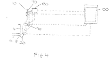
- the system comprises identification means 90 as shown in Figure 4 for identifying the user of the urinal (such as an RFID reader which is configured to read an RFID tag attached to the user of the urinal).
- the processor may be configured to receive a third signal containing third information from the identification means 90, and process the third information along with the first information to generate the second signal.
- the system effectively allows for the system to generate a second signal which can be used to indicate a status or condition of the user of the urinal based on the content of their urine (such as the concentration of the urine).
- the processor may be located anywhere in the system - for instance in the casing 22 next to the sensor 20, at the device, or some other remote location.
- signals passed between any of the processor, the sensor 20, the battery, the flush valve 50, the light source 60, and the spreader 70, and the device may be transmitted using any appropriate communication means, including Bluetooth or other wireless communication means.
- the above therefore describes various systems and methods which may be used to monitor blockages or leakages in the urinal and provide an indication of these malfunctions to a user or a party in charge of maintenance, and relates to method of using information taken from a sensor system associated with a urinal.
- the operation of a flush valve for the urinal may be prohibited to prevent flooding of the urinal.
- the outlet pipe provided in the system may comprise a length of a portion of the outlet pipe which is adjustable.
- the length of the upstream pipe section 14 is adjustable.
- the senor may be positioned directly underneath the outlet 11 of the urinal 10, as shown in Figure 1 , such to increase the effectiveness of the sensor at detecting small amounts of fluid passing out from the outlet 11 through the outlet pipe 12.
- an end of the outlet pipe 12 proximal the outlet 11 may be provided with a flow restricting means, such as a reduction cone, for controlling the maximum flow rate of fluid passing through the outlet pipe 12 at any given time.
- the senor may be powered by a mains electricity supply, with our without a corresponding battery.
- the senor 20 need not expressly be located at the interface pipe section 18 of the outlet pipe 12, but may instead be positioned anywhere on or around the outlet pipe 12 such that the sensor 20 is operable to perform its function of detecting the presence of fluid in the outlet pipe 12. To that effect, in one embodiment, the sensor 20 may be in contact with an exterior surface of the outlet pipe 12.
- Various embodiments of the invention may suitably comprise, consist of, or consist essentially of, appropriate combinations of the disclosed elements, components, features, parts, steps, means, etc., other than those specifically described herein.
- this disclosure may include other inventions not presently claimed, but which may be claimed in future.
Landscapes
- Engineering & Computer Science (AREA)
- Health & Medical Sciences (AREA)
- Life Sciences & Earth Sciences (AREA)
- Public Health (AREA)
- Hydrology & Water Resources (AREA)
- Water Supply & Treatment (AREA)
- Physics & Mathematics (AREA)
- General Physics & Mathematics (AREA)
- Aviation & Aerospace Engineering (AREA)
- Environmental & Geological Engineering (AREA)
- Physiology (AREA)
- Urology & Nephrology (AREA)
- Biophysics (AREA)
- Pathology (AREA)
- Biomedical Technology (AREA)
- Heart & Thoracic Surgery (AREA)
- Medical Informatics (AREA)
- Molecular Biology (AREA)
- Surgery (AREA)
- Animal Behavior & Ethology (AREA)
- General Health & Medical Sciences (AREA)
- Veterinary Medicine (AREA)
- Sanitary Device For Flush Toilet (AREA)
Abstract
Description
- The present invention relates particularly, but not exclusively, to a sensor system for a urinal. The invention may be used to monitor blockages in the urinal and provide an indication of these blockages or reduced flow to a user or a party in charge of maintenance. The invention may also be used in situations where it is desirable to monitor usage of the urinal or where the urine itself is desired to be monitored. Such monitoring allows optimisation of the flushing frequency and the flush timings of the urinal.
- The invention further relates to a method of use of the information taken from the sensor system.
- The urinal sensor system is able to accurately determine when the urinal is used and when there is a blockage, or leakage, in the urinal.
- Urinal sensor systems exist in the art. Current urinal sensor systems involve locating a sensor on the back of the urinal bowl itself. Thus, in order for the sensor to detect that the urinal is in use, it is necessary that the urine contacts with the urinal bowl at the exact position in which the sensor is located. If the urine does contact the urinal at this position, the sensor system detects that the urinal is in use. If however the urine does not contact the urinal at this position, the sensor is not able to detect that the urinal is in use.
- Furthermore, the urinal sensor systems designed in this way are not able to detect blockages in the outlet pipe of the urinal and are only able to detect blockages in the urinal bowl itself when the urine reaches the level of the sensor on the back of the bowl. Only at this point is the sensor able to determine that the urinal is blocked. Once this point has been reached, it is likely that the level is too high and leakage of the urine is occurred. This is unsanitary.
- Therefore, there is a need to provide a urinal sensor system which is able to more accurately determine when the urinal is in use.
- The inventors have devised an alternative positioning for a sensor system for the urinal. The positioning of the sensor in the present invention enables accurate monitoring of urinal usage and enables a user to be notified when the urinal is blocked. If the urinal is detected as being blocked, further flushing of the urinal is prevented in order to prevent further problems.
- Furthermore, the inventors have developed a novel method of using the information from the sensor system.
- Aspects of the invention are set out in the accompanying claims.
- Viewed from a first aspect there is provided a system for use with an outlet pipe of a sanitary ware product, wherein the system comprises a processor, and a sensor operable to detect the presence of fluid in the outlet pipe; wherein the sensor is configured to output to the processor at least one first signal containing first information relating to the presence of fluid in the outlet pipe; wherein the processor is configured to process the first information from the at least one first signal to generate a second signal, and output this second signal to a device.
- An arrangement is thereby provided that allows fluid contained in the outlet pipe to be sensed by the sensor for detecting the presence of liquid in the outlet pipe. Based on the information from the sensor, the processor can use this information to generate an appropriate signal for outputting to a given device as required, such as a signal output to a flush valve to instruct a flushing operation of the sanitary ware product, or a signal to a device to indicate usage statistics relating to the sanitary ware product.
- In some embodiments, the sensor is operable to detect the presence of fluid in the outlet pipe based on fluid contacting a portion of the outlet pipe which the sensor is connected to.
- In some embodiments, the sensor may be a non-contact sensor, such as an inductive sensor, or a capacitive sensor, for detecting fluid through the outlet pipe. In other embodiments, the sensor may be a pressure sensor.
- In some embodiments, the at least one first signal may comprise a plurality of first signals, each first signal containing first information relating to the presence of fluid in the outlet pipe at a different point in time, wherein the processor is configured to process the first information from the plurality of first signals to generate the second signal.
- In such cases, the processor may be configured to process the first information from the plurality of first signals to generate second information relating to the frequency in which the sanitary ware product is used in a period of time, wherein the second signal is generated based on the second information. Such second information can then be used to prepare usage statistics relating to the sanitary ware product.
- In some embodiments, the processor may be configured to process the first information from the plurality of first signals to derive second information relating to a period of time in which fluid is present in the outlet pipe, wherein the second signal is generated based on the second information. There, the processor may be further configured to determine a blockage in the event the period of time exceeds a threshold amount of time.
- In some embodiments, the second signal may comprise an instruction for controlling the operation of a light source from a sanitary ware product.
- The second signal may in some embodiments comprise an instruction for controlling the operation of a flush valve from a sanitary ware product.
- In some embodiments, the system may further comprise a casing which is attachable to an outlet pipe of a sanitary ware product, wherein the sensor is located inside the casing.
- The system may further comprise a shroud which is configured to extend around a portion of an outlet pipe of a sanitary ware product, wherein the casing is configured to rest on a surface of the shroud for supporting the casing on the shroud.
- In some embodiments, the device may be a remote location from the sensor for sending and receiving information from the sensor. The device may be operable to send information to the sensor for controlling the operation of the sensor.
- In some embodiments, the device may be at least one of a computer or a handheld device.
- In other embodiments, the device may be a flush valve, or a light source from a sanitary ware product.
- The system in some embodiments may further comprise an outlet pipe of a sanitary ware product, wherein the sensor is attached to the outlet pipe. In such cases, the sensor may be in contact with an exterior surface of the outlet pipe.
- In some embodiments, the outlet pipe may comprise an end located upstream of the sensor, wherein the end of the outlet pipe is connectable to an outlet of the sanitary ware product, and wherein the sensor is positioned directly underneath the end of the outlet pipe. By positioning the sensor directly underneath the end of the outlet pipe, and thus the outlet to which it is connected to, this increases the effectiveness of the sensor at detecting small amounts of fluid passing out from the outlet through the outlet pipe.
- The outlet pipe may comprise an upstream pipe section extending in a first direction and a downstream pipe section extending in a second direction different from the first direction, and an interface pipe section located at the interface of the upstream and downstream pipe sections, wherein the sensor is in contact with the interface pipe section.
- In some embodiments, the sensor may be in contact with a flat surface from the interface pipe section. In particular embodiments, the flat surface may be orientated at between twenty degrees and thirty degrees with respect to the horizontal. At such orientations, the flat surface is better orientated to prevent fluid pooling at the vicinity of the sensor.
- In some embodiments, the sensor may be positioned above the upstream pipe section to reduce the extent of fluid located in the downstream pipe section from pooling at the vicinity of the sensor.
- To allow the system to be more easily retrofitted on an existing sanitary ware product, a length of a portion of the outlet pipe from the system may be adjustable. In some embodiments, the portion of the outlet pipe may be a portion of the upstream pipe section. In other embodiments, the length may be a vertical length.
- In some embodiments, the sensor may be positioned directly underneath an outlet of the sanitary ware product, wherein the outlet is connected to the outlet pipe.
- In a particular embodiment, the system may be used with a sanitary ware product in the form of a urinal.
- According to a second aspect, there is provided a method of retro-fitting a sanitary ware product comprising an outlet pipe using the system according to the first aspect.
- According to a third aspect, there is provided a sanitary ware product comprising an outlet pipe and a sensor attached to the outlet pipe; wherein the sensor is operable to detect the presence of fluid in the outlet pipe, and is configured to output at least one first signal containing first information relating to the presence of fluid in the outlet pipe.
- In such embodiments, the sanitary ware product may comprise an outlet connected to the outlet pipe, wherein the sensor is positioned directly underneath the outlet. By positioning the sensor directly underneath the outlet of the sanitary ware product, this increases the effectiveness of the sensor at detecting small amounts of fluid passing out from the outlet through the outlet pipe.
- According to a fourth aspect, there is provided a method for monitoring the use of a sanitary ware product comprising an outlet pipe, using a system comprising a processor and a sensor operable to detect the presence of fluid in the outlet pipe; wherein the method comprises the steps of:
- using the sensor to output to the processor at least one first signal containing first information relating to the presence of fluid in the outlet pipe; and
- using the processor to process the first information from the at least one first signal to generate a second signal.
- In such a method, the system may further comprise identification means for identifying the user of the sanitary ware product, wherein the method further comprises the steps of:
- using the identification means to output to the processor a third signal containing third information indicative of the identify of the user of the urinal; and
- using the processor to process the third information along with the first information to generate the second signal.
- In some embodiments, the method may further comprise processing the second signal to indicate a status or condition of the user. The status or condition may comprise at least one of the level of hydration of the user; diabetes; and/or or a urinary tract infection.
- Aspects of the invention will now be described, by way of example only, with reference to the accompanying figures in which:
-
Figure 1 shows a cross section view of a sanitary ware product comprising an outlet pipe using a sensor operable to detect the presence of fluid in the outlet pipe; -
Figure 2 shows a perspective view of the outlet pipe and the sensor fromFigure 1 ; -
Figure 3 shows a photograph of the sanitary ware product fromFigure 1 , and also shows a spreader for cleaning fluid and light source for use with the sanitary ware product. -
Figure 4 shows a schematic of system showing the interaction of the sensor fromFigure 1 with other components from the system; and -
Figure 5 shows exemplary screenshots of a graphical user interface for use with the sensor shown inFigure 1 . - While the present teachings are susceptible to various modifications and alternative forms, specific embodiments are shown by way of example in the drawings and are herein described in detail. It should be understood, however, that drawings and detailed description thereto are not intended to limit the scope to the particular form disclosed, but on the contrary, the scope is to cover all modifications, equivalents and alternatives falling within the spirit and scope defined by the appended claims.
- As used in this specification, the words "comprises", "comprising", and similar words, are not to be interpreted in an exclusive or exhaustive sense. In other words, they are intended to mean "including, but not limited to".
- It will be recognised that the features of the aspects of the invention(s) described herein can conveniently and interchangeably be used in any suitable combination. It will also be recognised that the invention covers not only individual embodiments but also combinations of the embodiments that have been discussed herein.
- The present teaching relates generally to a sensor system for a sanitary ware product, such as a urinal.
- With reference to
Figure 1 , there is shown a system comprising a sanitary ware product in the form of aurinal 10. Theurinal 10 defines an outlet 11 leading to a top end of anoutlet pipe 12. Theoutlet pipe 12 is formed of three sections in the form of anupstream pipe section 14 extending from theoutlet 12 in a first direction D1 and adownstream pipe section 16 extending in a second direction D2 different from the first direction D1, and aninterface pipe section 18 located at the interface of the upstream anddownstream pipe sections 14;16. - The system comprises a
sensor 20 which is operable to detect the presence of fluid in theoutlet pipe 12. The sensor is in contact with theinterface pipe section 18, and is attached to theoutlet pipe 12. Thesensor 20 is best shown with reference toFigure 2 which shows acasing 22 which is attachable to theoutlet pipe 12, wherein thesensor 20 is located inside thecasing 22, along with a battery (not shown in the Figures) for powering the sensor. In one embodiment, the casing may be made of a plastic such as ABS. The sensor itself may take the form of a non-contact sensor, such as an inductive sensor, or a capacitive sensor, for detecting fluid through the outlet pipe.. In another embodiment, thesensor 20 may take the form of a pressure sensor which is operable to detect the presence of fluid in the outlet pipe based on fluid contacting a portion of the outlet pipe which the sensor is connected to. In the embodiment shown inFigure 1 , that portion of theoutlet pipe 12 is aflat surface 24 from theinterface pipe section 18 which thesensor 20 is in contact with. Theflat surface 24 may be located underneath the outlet 11 of theurinal 10 such that fluid (such as urine) passing out from the outlet 11 into theoutlet pipe 12 falls onto theflat surface 24, and then runs off theflat surface 24 down towards thedownstream pipe section 16 and then on into a drain (not shown in the Figures). In some embodiments, theflat surface 24 may be orientated at between twenty degrees and thirty degrees with respect to the horizontal. In other embodiments, the lower bound of this angular range may be five, ten, or fifteen degrees, as opposed to twenty degrees. The upper bound of this angular range may also be forty, forty five, fifty, sixty, seventy or eighty degrees, as opposed to thirty degrees. In one particular embodiment, theflat surface 24 may be orientated at twenty five degrees with respect to the horizontal. At such orientations, the flat surface is better orientated to prevent fluid pooling at the vicinity of the sensor. - To help secure the
casing 22 with respect to theoutlet pipe 12, the system may further comprise ashroud 26 which is configured to extend around a portion of theoutlet pipe 12, and preferably such that thecasing 22 is further configured to rest on asurface 28 of theshroud 26 for supporting thecasing 22 on theshroud 26. It will be appreciated that a clip or any other attachment means may be used to attach the shroud to either the casing or the outlet pipe. In one embodiment, the shroud may be made of a plastic such as polypropylene. - The operation of the
sensor 20 will now be described with reference to the Figures. In the embodiment shown inFigure 2 , the sensor is placed into contact with theflat surface 24 from theinterface pipe section 18 using thecasing 22. The sensor then operates to detect the presence of fluid in the outlet pipe by detecting fluid which impinges on theflat surface 24. Since thesensor 20 is in contact with theflat surface 24, thesensor 20 is configured to detect the presence of fluid in theoutlet pipe 12 passing through the outlet pipe. As previously discussed, thesensor 20 used to detect the fluid may be a non-contact sensor, or some other sensor such as a pressure sensor. Based on the detection of such fluid, thesensor 20 generates a first signal containing first information relating to the presence of fluid in the outlet pipe. Depending on the configuration of thesensor 20, the sensor may generate the first signal in a number of different ways. In exemplary embodiments, thesensor 20 may be configured to generate the first signal upon each detection of fluid on the flat surface; or generate a plurality of first signals at regular time intervals (e.g. a first signal generated every few seconds). - The
sensor 20 is configured to output the first signal to a processor. The location of the processor may be within thecasing 22 or at a location remote from thesensor 20. As required, thesensor 20 may be connected to a transmitter, or a transceiver, which may be located in thecasing 22, for transmitting the first signal to the processor. - The processor is configured to process the first information from the first signal (or plurality of first signals) to generate a second signal, and output this second signal to a device.
- In one particular embodiment, the processor is configured to process the first information from the first signals to generate second information relating to the frequency in which the sanitary ware product is used in a period of time, wherein the second signal is generated based on the second information. The second information has several applications. For instance, in a broad sense, the second information is indicative of the general usage of the
urinal 10. In a particular embodiment, the second information can be indicative of how often the urinal is being used, and can be used to then determine how often flushing/cleaning or theurinal 10 should be carried out. - In another embodiment, the processor may be configured to process the first information from the first signals to derive second information relating to a period of time in which fluid is present in the outlet pipe, wherein the second signal is generated based on the second information. In some embodiments, the processor may determine a blockage in the
outlet pipe 12 in the event a period of time in which fluid is present in theoutlet pipe 12 exceeds a threshold amount of time, or in the event a predetermined number of consecutive first signals contain first information indicating the presence of fluid in theoutlet pipe 12. In other embodiments, the processor may determine a leakage from theurinal 10 or theoutlet pipe 12 based on the first information from thesensor 20. - The processor is configured to output the second signal to a device. The device could be one of a plurality of different objects/locations depending on the configuration of the processor and the system.
- In some embodiments, the device may be a
flush valve 50 from a urinal, such as the flush valve shownFigure 1 , and the second signal may comprise an instruction for controlling the operation of theflush valve 50. In some embodiments, the instruction for controlling the operation of theflush valve 50 may be an instruction to perform a flushing operation using the flush valve, or an instruction to control the frequency of the operation of theflush valve 50. In some cases the instruction for controlling the operation of theflush valve 50 may be an instruction to prohibit the operation of the flush valve (for instance, in the event the processor determines a blockage or leakage in the outlet pipe based on the first information from the sensor 20). - In another embodiment, the processor may be configured to prevent the operation of the
flush valve 50 at a predetermined period of time, or may be configured to prohibit the operation of the flush valve when the first information indicates the presence of fluid in the outlet pipe. These embodiments would be particularly suited for urinals used in forums such as stadiums, theatres, and cinemas, where use of the urinal may peak at particular times (e.g. during an interval, or at the end, of a game/performance). During such peak times, the configuration of the processor may prevent the operation of the flush valve during such times, and allow operation of the flush valve after the peak time has passed. - In the above embodiments therefore, the processor processes the first information from the
sensor 20 to control the operation of theflush valve 50 depending on the usage/condition of the urinal. - In further embodiments, the device may be a
light source 60 from a urinal, such as the light source shown in the urinal ofFigure 3 , and the second signal may comprise an instruction for controlling the operation of thelight source 60. It is envisaged in such embodiments that thelight source 60 may be used to indicate a condition of the urinal and/or its outlet pipe. For instance, the light source may be configured to operate in a first condition during a normal, working, operation of theurinal 10. In some embodiments, the first condition may be the light source turned off, or emitting a first coloured light (e.g. green light). The light source may be configured to also operate in a second condition during a malfunction or a blockage, or a leakage, in theurinal 10. In some embodiments, the second condition may be the light source flashing, and/or emitting a second coloured light (e.g. red light) different from the first coloured light. In these embodiments, the processor processes the first information from the sensor to control the operation of the light source for indicating to a user the working state of the urinal. In the embodiments where the light source is configured to flash, the light source may comprise a first operation where the light source flashes with a first periodicity (e.g. one flash every second), and a second operation where the light source flashes with a second periodicity (e.g. one flash every five seconds) which is different from the first periodicity. The different set of flashes in the above embodiments, whilst at different periodicities, may be the same colour. In some embodiments, the different operations for the light source may be indicative of a different working state of the urinal. - In some embodiments, the instruction for controlling the operation of the
flush valve 50 may be an instruction to perform a flushing operation using the flush valve, or an instruction to control the frequency of the operation of theflush valve 50. - With reference to the urinal shown in
Figure 3 , theurinal 10 also comprises a fluid outlet in the form of aspreader 70 from which cleaning fluid is emitted into theurinal 10. Thespreader 70 is operably connected to theflush valve 50 for emitting cleaning fluid (such as water) into theurinal 10 during a flushing operation. In the particular embodiment ofFigure 3 , thespreader 70 comprises thelight source 60, and light 75 from thelight source 60 is configured to emanate from around thespreader 70 when thelight source 60 is in use. - In terms of the second signal generated by the processor, in some embodiments this second signal may be output to a device which is remote from the sensor (a remote device) for sending and receiving information from the sensor, wherein the remote device is operable to send information to the sensor for controlling the operation of the sensor. Such a device may comprise at least one of a computer or a handheld device. In some embodiments, the device may be configured to send and receive information from a plurality of
different sensors 20, each sensor attributed to a separate sanitary ware product. - A user interface may be provided on the device for controlling the operation of the or each
sensor 20 which the device is in communication with. An exemplary embodiment of such auser interface 100 is shown inFigure 5 . The user interface may be configured to process the second information from each received second signal to output an operating condition or at least one usage statistic for the (each)urinal 10 to which thesensor 20 is attached. In some embodiments, the usage statistic may be the period of time since thesensor 20 was last activated, or the period of time since thesensor 20 was installed on theurinal 10. - The device is some embodiments may be configured to allow a user to control an operating parameter of the
sensor 20 and/or an operating parameter of aflush valve 50 associated with thesensor 20. In some embodiments, the operating parameter may be the flow rate of cleaning fluid during a flushing operation, the duration of a flushing operation, a minimum period of time between flushing operations, and/or a sensitivity of thesensor 20. - In some embodiments, depending on the type of sensor used, it is envisaged that the
sensor 20 may be configured to detect a property of the fluid in the outlet pipe, for instance the salt levels in the fluid, or configured to detect a predetermined substance, or an amount thereof. This may be advantageous, particularly when the system comprises identification means 90 as shown inFigure 4 for identifying the user of the urinal (such as an RFID reader which is configured to read an RFID tag attached to the user of the urinal). In such arrangements, which are particularly suited to hospitals where patient monitoring is desirable, the processor may be configured to receive a third signal containing third information from the identification means 90, and process the third information along with the first information to generate the second signal. With this arrangement, the system effectively allows for the system to generate a second signal which can be used to indicate a status or condition of the user of the urinal based on the content of their urine (such as the concentration of the urine). - In terms of the location of the processor, with reference to
Figure 4 , it will be appreciated that it may be located anywhere in the system - for instance in thecasing 22 next to thesensor 20, at the device, or some other remote location. As required, signals passed between any of the processor, thesensor 20, the battery, theflush valve 50, thelight source 60, and thespreader 70, and the device may be transmitted using any appropriate communication means, including Bluetooth or other wireless communication means. - The above therefore describes various systems and methods which may be used to monitor blockages or leakages in the urinal and provide an indication of these malfunctions to a user or a party in charge of maintenance, and relates to method of using information taken from a sensor system associated with a urinal. In the event that a blockage is detected based on the information from the sensor system, the operation of a flush valve for the urinal may be prohibited to prevent flooding of the urinal.
- It will be appreciated that various other modifications can be made to the systems and method described herein.
- For instance, in one embodiment, to help assist the system being retrofitted to urinals of differing sizes having different length outlet pipes, the outlet pipe provided in the system may comprise a length of a portion of the outlet pipe which is adjustable. In the embodiment shown in
Figure 2 , the length of theupstream pipe section 14 is adjustable. For the sake of completeness, an intention of some embodiments of the system described herein is for the system to be retrofitting a sanitary ware product comprising an outlet pipe using the system. - In relation to the position of the
sensor 20, in some embodiments the sensor may be positioned directly underneath the outlet 11 of theurinal 10, as shown inFigure 1 , such to increase the effectiveness of the sensor at detecting small amounts of fluid passing out from the outlet 11 through theoutlet pipe 12. To assist with the detection of fluid by thesensor 20, in some embodiments an end of theoutlet pipe 12 proximal the outlet 11 may be provided with a flow restricting means, such as a reduction cone, for controlling the maximum flow rate of fluid passing through theoutlet pipe 12 at any given time. - In some embodiments, the sensor may be powered by a mains electricity supply, with our without a corresponding battery.
- Also in relation to the position of the sensor of the
sensor 20, it will be appreciated that thesensor 20 need not expressly be located at theinterface pipe section 18 of theoutlet pipe 12, but may instead be positioned anywhere on or around theoutlet pipe 12 such that thesensor 20 is operable to perform its function of detecting the presence of fluid in theoutlet pipe 12. To that effect, in one embodiment, thesensor 20 may be in contact with an exterior surface of theoutlet pipe 12. - It will also be appreciated the systems described herein, which have been described in some embodiments with reference to a urinal, may be used on any sanitary ware product comprising an outlet pipe, such as a bath, a shower, or a sink.
- The various embodiments described herein are presented only to assist in understanding and teaching the claimed features. These embodiments are provided as a representative sample of embodiments only, and are not exhaustive and/or exclusive. It is to be understood that advantages, embodiments, examples, functions, features, structures, and/or other aspects described herein are not to be considered limitations on the scope of the invention as defined by the claims or limitations on equivalents to the claims, and that other embodiments may be utilised and modifications may be made without departing from the spirit and scope of the claimed invention.
- Various embodiments of the invention may suitably comprise, consist of, or consist essentially of, appropriate combinations of the disclosed elements, components, features, parts, steps, means, etc., other than those specifically described herein. In addition, this disclosure may include other inventions not presently claimed, but which may be claimed in future.
-
- 1. A system for use with an outlet pipe of a sanitary ware product, wherein the system comprises a processor, and a sensor operable to detect the presence of fluid in the outlet pipe; wherein the sensor is configured to output to the processor at least one first signal containing first information relating to the presence of fluid in the outlet pipe; wherein the processor is configured to process the first information from the at least one first signal to generate a second signal, and output this second signal to a device.
- 2. A system according to clause 1, wherein the sensor is operable to detect the presence of fluid in the outlet pipe based on fluid contacting a portion of the outlet pipe which the sensor is connected to.
- 3. A system according to
clause 1 or 2, wherein the sensor is a non-contact sensor. - 4. A system according to any preceding clause, wherein the at least one first signal comprises a plurality of first signals, each first signal containing first information relating to the presence of fluid in the outlet pipe at a different point in time, wherein the processor is configured to process the first information from the plurality of first signals to generate the second signal.
- 5. A system according to clause 4, wherein the processor is configured to process the first information from the plurality of first signals to generate second information relating to the frequency in which the sanitary ware product is used in a period of time, wherein the second signal is generated based on the second information.
- 6. A system according to clause 4 or 5, wherein the processor is configured to process the first information from the plurality of first signals to derive second information relating to a period of time in which fluid is present in the outlet pipe, wherein the second signal is generated based on the second information.
- 7. A system according to clause 6, wherein the processor is configured to determine a blockage in the event the period of time exceeds a threshold amount of time.
- 8. A system according to any preceding clause, wherein the second signal comprises an instruction for controlling the operation of a light source from a sanitary ware product.
- 9. A system according to any preceding clause, wherein the second signal comprises an instruction for controlling the operation of a flush valve from a sanitary ware product.
- 10. A system according to any preceding clause, further comprising a casing which is attachable to an outlet pipe of a sanitary ware product, wherein the sensor is located inside the casing.
- 11. A system according to
clause 10, further comprising a shroud which is configured to extend around a portion of an outlet pipe of a sanitary ware product, wherein the casing is configured to rest on a surface of the shroud for supporting the casing on the shroud. - 12. A system according to any preceding clause, wherein the device is a remote location from the sensor for sending and receiving information from the sensor, wherein the remote location is further operable to send information to the sensor for controlling the operation of the sensor.
- 13. A system according to any preceding clause, wherein the device is at least one of a computer or a handheld device.
- 14. A system according to any preceding clause, wherein the device is a flush valve.
- 15. A system according to any preceding clause, wherein the device is a light source from a sanitary ware product.
- 16. A system according to any preceding clause, wherein the system further comprises an outlet pipe of a sanitary ware product, wherein the sensor is attached to the outlet pipe.
- 17. A system according to
clause 16, wherein the sensor is in contact with an exterior surface of the outlet pipe. - 18. A system according to
clause 16 or 17, wherein the outlet pipe comprises an end located upstream of the sensor, wherein the end of the outlet pipe is connectable to an outlet of the sanitary ware product, and wherein the sensor is positioned directly underneath the end of the outlet pipe. - 19. A system according to
clause - 20. A system according to clause 19, wherein the sensor is in contact with a flat surface from the interface pipe section.
- 21. A system according to
clause 20, wherein the flat surface is orientated at between twenty degrees and thirty degrees with respect to the horizontal. - 22. A system according to any of
clause 16 to 21, wherein a length of a portion of the outlet pipe is adjustable. - 23. A system according to any preceding clause, further comprising identification means for identifying the user of the sanitary ware product, wherein the identification means is configured to output to the processor a third signal containing third information indicative of the identify of the user of the urinal, wherein the processor is configured to process the third information along with the first information to generate the second signal.
- 24. A system according to any preceding clause, wherein the sensor is further operable to detect at least one property of fluid in the outlet pipe.
- 25. A system according to any preceding clause wherein the sanitary ware product is a urinal.
- 26. A method of retro-fitting a sanitary ware product comprising an outlet pipe using the system of any preceding clause.
- 27. A sanitary ware product comprising an outlet pipe and a sensor attached to the outlet pipe; wherein the sensor is operable to detect the presence of fluid in the outlet pipe, and is configured to output at least one first signal containing first information relating to the presence of fluid in the outlet pipe.
- 28. A sanitary ware product according to clause 27, wherein the sanitary ware product comprises an outlet connected to the outlet pipe, wherein the sensor is positioned directly underneath the outlet.
- 29. A method for monitoring the use of a sanitary ware product comprising an outlet pipe, using a system comprising a processor and a sensor operable to detect the presence of fluid in the outlet pipe; wherein the method comprises the steps of:
- using the sensor to output to the processor at least one first signal containing first information relating to the presence of fluid in the outlet pipe; and
- using the processor to process the first information from the at least one first signal to generate a second signal.
- 30. A method according to clause 29, wherein the system further comprises identification means for identifying the user of the sanitary ware product, wherein the method further comprises the steps of:
- using the identification means to output to the processor a third signal containing third information indicative of the identify of the user of the urinal; and
- using the processor to process the third information along with the first information to generate the second signal.
- 31. A method according to clause 30, wherein the method further comprises processing the second signal to indicate a status or condition of the user.
- 32. A method according to clause 31, wherein the status or condition comprises the level of hydration of the user.
Claims (18)
- A system for use with an outlet pipe of a sanitary ware product, wherein the system comprises a processor, and a sensor operable to detect the presence of fluid in the outlet pipe; wherein the sensor is configured to output to the processor at least one first signal containing first information relating to the presence of fluid in the outlet pipe; wherein the processor is configured to process the first information from the at least one first signal to generate a second signal, and output this second signal to a device;
wherein the system further comprises an outlet pipe of a sanitary ware product, wherein the sensor is attached to the outlet pipe; and
wherein the outlet pipe comprises an end located upstream of the sensor, wherein the end of the outlet pipe is connectable to an outlet of the sanitary ware product, and wherein the sensor is positioned, in use of the system, directly underneath the end of the outlet pipe. - A system according to claim 1, wherein the sensor is operable to detect the presence of fluid in the outlet pipe based on fluid contacting a portion of the outlet pipe which the sensor is connected to.
- A system according to claim 1 or 2, wherein the sensor is a non-contact sensor.
- A system according to any preceding claim, wherein the at least one first signal comprises a plurality of first signals, each first signal containing first information relating to the presence of fluid in the outlet pipe at a different point in time, wherein the processor is configured to process the first information from the plurality of first signals to generate the second signal.
- A system according to claim 4, wherein the processor is configured to process the first information from the plurality of first signals to generate second information relating to the frequency in which the sanitary ware product is used in a period of time, wherein the second signal is generated based on the second information.
- A system according to claim 4, wherein the processor is configured to process the first information from the plurality of first signals to derive second information relating to a period of time in which fluid is present in the outlet pipe, wherein the second signal is generated based on the second information, wherein the processor is configured to determine a blockage in the event the period of time exceeds a threshold amount of time.
- A system according to any preceding claim, wherein the second signal comprises an instruction for controlling the operation of either a light source or a flush valve from a sanitary ware product.
- A system according to any preceding claim, further comprising a casing which is attachable to the outlet pipe of a sanitary ware product, wherein the sensor is located inside the casing.
- A system according to claim 8, further comprising a shroud which is configured to extend around a portion of the outlet pipe of a sanitary ware product, wherein the casing is configured to rest on a surface of the shroud for supporting the casing on the shroud.
- A system according to any preceding claim, wherein the device is located at a remote location from the sensor for sending and receiving information from the sensor, wherein the remote location is further operable to send information to the sensor for controlling the operation of the sensor.
- A system according to any preceding claim, wherein the device is at least one of:i) a computer or a handheld device;ii) a flush valve; oriii) a light source from a sanitary ware product.
- A system according to any preceding claim, wherein the sensor is in contact with an exterior surface of the outlet pipe.
- A system according to any preceding claim, wherein the outlet pipe comprises an upstream pipe section extending in a first direction and a downstream pipe section extending in a second direction different from the first direction, and an interface pipe section located at the interface of the upstream and downstream pipe sections, wherein the sensor is in contact with the interface pipe section.
- A system according to claim 13, wherein the sensor is in contact with a flat surface from the interface pipe section.
- A system according to claim 14, wherein the flat surface, in use of the system, is orientated at between twenty degrees and thirty degrees with respect to the horizontal.
- A system according to any preceding claim, wherein a length of a portion of the outlet pipe is adjustable.
- A system according to any preceding claim wherein the sanitary ware product is a urinal.
- A method for monitoring the use of a sanitary ware product comprising an outlet pipe, using a system comprising a processor and a sensor operable to detect the presence of fluid in the outlet pipe; wherein the method comprises the steps of:using the sensor to output to the processor at least one first signal containing first information relating to the presence of fluid in the outlet pipe; andusing the processor to process the first information from the at least one first signal to generate a second signal;wherein the sensor is attached to the outlet pipe; andwherein the outlet pipe comprises an end located upstream of the sensor, wherein the end of the outlet pipe is connectable to an outlet of the sanitary ware product, and wherein the sensor is positioned, in use, directly underneath the end of the outlet pipe.
Applications Claiming Priority (1)
| Application Number | Priority Date | Filing Date | Title |
|---|---|---|---|
| GB1903162.4A GB2582020A (en) | 2019-03-08 | 2019-03-08 | Urinal sensor system |
Publications (2)
| Publication Number | Publication Date |
|---|---|
| EP3705895A1 true EP3705895A1 (en) | 2020-09-09 |
| EP3705895B1 EP3705895B1 (en) | 2023-05-03 |
Family
ID=66380508
Family Applications (1)
| Application Number | Title | Priority Date | Filing Date |
|---|---|---|---|
| EP20161429.4A Active EP3705895B1 (en) | 2019-03-08 | 2020-03-06 | Urinal sensor system |
Country Status (2)
| Country | Link |
|---|---|
| EP (1) | EP3705895B1 (en) |
| GB (1) | GB2582020A (en) |
Cited By (1)
| Publication number | Priority date | Publication date | Assignee | Title |
|---|---|---|---|---|
| WO2021156398A1 (en) * | 2020-02-07 | 2021-08-12 | Grohe Ag | Method for identifying an impending outlet blockage |
Citations (6)
| Publication number | Priority date | Publication date | Assignee | Title |
|---|---|---|---|---|
| GB189603014A (en) * | 1896-02-10 | 1896-12-19 | William Shoosmith | Improvements in Joints or Unions for Pipes and the like. |
| GB2201699A (en) * | 1987-02-23 | 1988-09-07 | John Lloyd Parry Jones | Automatically flushing urinal |
| GB2263711A (en) * | 1992-01-28 | 1993-08-04 | Armitage Shanks Ltd | Flushing control means for a urinal |
| GB2279086A (en) * | 1993-06-17 | 1994-12-21 | Michael Campbell Hastie | Flushing water control apparatus for a urinal |
| US20100146691A1 (en) * | 2008-10-31 | 2010-06-17 | Mark Kit Jiun Chan | Intelligent flushing system |
| CN207988068U (en) * | 2017-10-27 | 2018-10-19 | 佛山市恒洁卫浴有限公司 | A kind of non-contact inductive urinating bucket and its induction flushing control system |
Family Cites Families (6)
| Publication number | Priority date | Publication date | Assignee | Title |
|---|---|---|---|---|
| FR2712404B1 (en) * | 1993-11-09 | 1996-02-09 | Sagelec Sarl | Method and device for controlling an apparatus. |
| JPH07189314A (en) * | 1993-12-27 | 1995-07-28 | Matsushita Electric Works Ltd | Automatic cleaning device for urinal |
| JPH08120744A (en) * | 1994-10-21 | 1996-05-14 | Mitsubishi Denki Bill Techno Service Kk | Urinal |
| FR2769094B1 (en) * | 1997-09-26 | 1999-11-05 | Presto Robinets Sa | DEVICE FOR DETECTING THE FLOW OF A LIQUID |
| AT9068U1 (en) * | 2006-03-06 | 2007-04-15 | Herbert Wimberger | FLOW WITH A SENSOR DEVICE AND METHOD FOR PURIFYING WASTE WATER |
| CN204898810U (en) * | 2015-08-03 | 2015-12-23 | 上海应用技术学院 | Intelligence water conservation urinal washing unit |
-
2019
- 2019-03-08 GB GB1903162.4A patent/GB2582020A/en not_active Withdrawn
-
2020
- 2020-03-06 EP EP20161429.4A patent/EP3705895B1/en active Active
Patent Citations (6)
| Publication number | Priority date | Publication date | Assignee | Title |
|---|---|---|---|---|
| GB189603014A (en) * | 1896-02-10 | 1896-12-19 | William Shoosmith | Improvements in Joints or Unions for Pipes and the like. |
| GB2201699A (en) * | 1987-02-23 | 1988-09-07 | John Lloyd Parry Jones | Automatically flushing urinal |
| GB2263711A (en) * | 1992-01-28 | 1993-08-04 | Armitage Shanks Ltd | Flushing control means for a urinal |
| GB2279086A (en) * | 1993-06-17 | 1994-12-21 | Michael Campbell Hastie | Flushing water control apparatus for a urinal |
| US20100146691A1 (en) * | 2008-10-31 | 2010-06-17 | Mark Kit Jiun Chan | Intelligent flushing system |
| CN207988068U (en) * | 2017-10-27 | 2018-10-19 | 佛山市恒洁卫浴有限公司 | A kind of non-contact inductive urinating bucket and its induction flushing control system |
Cited By (1)
| Publication number | Priority date | Publication date | Assignee | Title |
|---|---|---|---|---|
| WO2021156398A1 (en) * | 2020-02-07 | 2021-08-12 | Grohe Ag | Method for identifying an impending outlet blockage |
Also Published As
| Publication number | Publication date |
|---|---|
| GB2582020A (en) | 2020-09-09 |
| GB201903162D0 (en) | 2019-04-24 |
| EP3705895B1 (en) | 2023-05-03 |
Similar Documents
| Publication | Publication Date | Title |
|---|---|---|
| US10107665B2 (en) | Toilet with flush jet fill tube flow meter | |
| US9725894B2 (en) | Fluid backflow management system and method of use thereof | |
| US7121292B2 (en) | Gray water reclamation system and method for providing and operating same | |
| US10590640B2 (en) | Automated plumbing system sensor warning system and method | |
| US8434172B2 (en) | Dual flush electronic flush valve | |
| DE502004002955D1 (en) | Device for automatically monitoring the flow of a fluid, in particular urine | |
| TW200728693A (en) | Flow measurement and control with bubble detection | |
| US5898375A (en) | Siphon alarm and restarting mechanism | |
| EP3705895B1 (en) | Urinal sensor system | |
| CA2665791A1 (en) | Dual flush electronic flush valve | |
| GB2590016A (en) | Water Flow Management System | |
| EP3204562B1 (en) | Assembly of a sewer and a sewer blockage detection system | |
| CN103234600A (en) | Residential quarter water pipeline monitoring system based on sensor | |
| WO2014163930A1 (en) | Apparatus and method for reducing cross-talk between capacitive sensors | |
| EP4186793A2 (en) | Systems and methods for detecting water leaks and/or preventing waste water overflow | |
| WO2018126172A1 (en) | Sensor system for toilet flush control | |
| CN117693672A (en) | Leak detection equipment | |
| CN204898810U (en) | Intelligence water conservation urinal washing unit | |
| JP2006183400A (en) | Automatic flushing device | |
| TW201305411A (en) | Early warning system and procedure of sewage water blocking | |
| JP2002285600A (en) | Drain pipe system | |
| CN203163829U (en) | Sensor-based water pipe monitoring system in residential area | |
| US20170067232A1 (en) | Water flow control and supply system | |
| CA2664248C (en) | Dual flush electronic flush valve | |
| JP2001084472A (en) | System for monitoring resident |
Legal Events
| Date | Code | Title | Description |
|---|---|---|---|
| PUAI | Public reference made under article 153(3) epc to a published international application that has entered the european phase |
Free format text: ORIGINAL CODE: 0009012 |
|
| STAA | Information on the status of an ep patent application or granted ep patent |
Free format text: STATUS: THE APPLICATION HAS BEEN PUBLISHED |
|
| AK | Designated contracting states |
Kind code of ref document: A1 Designated state(s): AL AT BE BG CH CY CZ DE DK EE ES FI FR GB GR HR HU IE IS IT LI LT LU LV MC MK MT NL NO PL PT RO RS SE SI SK SM TR |
|
| AX | Request for extension of the european patent |
Extension state: BA ME |
|
| STAA | Information on the status of an ep patent application or granted ep patent |
Free format text: STATUS: REQUEST FOR EXAMINATION WAS MADE |
|
| 17P | Request for examination filed |
Effective date: 20210208 |
|
| RBV | Designated contracting states (corrected) |
Designated state(s): AL AT BE BG CH CY CZ DE DK EE ES FI FR GB GR HR HU IE IS IT LI LT LU LV MC MK MT NL NO PL PT RO RS SE SI SK SM TR |
|
| STAA | Information on the status of an ep patent application or granted ep patent |
Free format text: STATUS: EXAMINATION IS IN PROGRESS |
|
| 17Q | First examination report despatched |
Effective date: 20211005 |
|
| REG | Reference to a national code |
Ref country code: DE Ref legal event code: R079 Ref document number: 602020010241 Country of ref document: DE Free format text: PREVIOUS MAIN CLASS: G01P0013000000 Ipc: E03D0013000000 |
|
| GRAP | Despatch of communication of intention to grant a patent |
Free format text: ORIGINAL CODE: EPIDOSNIGR1 |
|
| STAA | Information on the status of an ep patent application or granted ep patent |
Free format text: STATUS: GRANT OF PATENT IS INTENDED |
|
| RIC1 | Information provided on ipc code assigned before grant |
Ipc: E03D 5/10 20060101ALI20221024BHEP Ipc: E03D 13/00 20060101AFI20221024BHEP |
|
| INTG | Intention to grant announced |
Effective date: 20221122 |
|
| GRAS | Grant fee paid |
Free format text: ORIGINAL CODE: EPIDOSNIGR3 |
|
| GRAA | (expected) grant |
Free format text: ORIGINAL CODE: 0009210 |
|
| STAA | Information on the status of an ep patent application or granted ep patent |
Free format text: STATUS: THE PATENT HAS BEEN GRANTED |
|
| AK | Designated contracting states |
Kind code of ref document: B1 Designated state(s): AL AT BE BG CH CY CZ DE DK EE ES FI FR GB GR HR HU IE IS IT LI LT LU LV MC MK MT NL NO PL PT RO RS SE SI SK SM TR |
|
| REG | Reference to a national code |
Ref country code: GB Ref legal event code: FG4D |
|
| REG | Reference to a national code |
Ref country code: AT Ref legal event code: REF Ref document number: 1564709 Country of ref document: AT Kind code of ref document: T Effective date: 20230515 Ref country code: CH Ref legal event code: EP |
|
| REG | Reference to a national code |
Ref country code: DE Ref legal event code: R096 Ref document number: 602020010241 Country of ref document: DE |
|
| REG | Reference to a national code |
Ref country code: IE Ref legal event code: FG4D |
|
| REG | Reference to a national code |
Ref country code: LT Ref legal event code: MG9D |
|
| REG | Reference to a national code |
Ref country code: NL Ref legal event code: MP Effective date: 20230503 |
|
| REG | Reference to a national code |
Ref country code: AT Ref legal event code: MK05 Ref document number: 1564709 Country of ref document: AT Kind code of ref document: T Effective date: 20230503 |
|
| PG25 | Lapsed in a contracting state [announced via postgrant information from national office to epo] |
Ref country code: SE Free format text: LAPSE BECAUSE OF FAILURE TO SUBMIT A TRANSLATION OF THE DESCRIPTION OR TO PAY THE FEE WITHIN THE PRESCRIBED TIME-LIMIT Effective date: 20230503 Ref country code: PT Free format text: LAPSE BECAUSE OF FAILURE TO SUBMIT A TRANSLATION OF THE DESCRIPTION OR TO PAY THE FEE WITHIN THE PRESCRIBED TIME-LIMIT Effective date: 20230904 Ref country code: NO Free format text: LAPSE BECAUSE OF FAILURE TO SUBMIT A TRANSLATION OF THE DESCRIPTION OR TO PAY THE FEE WITHIN THE PRESCRIBED TIME-LIMIT Effective date: 20230803 Ref country code: NL Free format text: LAPSE BECAUSE OF FAILURE TO SUBMIT A TRANSLATION OF THE DESCRIPTION OR TO PAY THE FEE WITHIN THE PRESCRIBED TIME-LIMIT Effective date: 20230503 Ref country code: ES Free format text: LAPSE BECAUSE OF FAILURE TO SUBMIT A TRANSLATION OF THE DESCRIPTION OR TO PAY THE FEE WITHIN THE PRESCRIBED TIME-LIMIT Effective date: 20230503 Ref country code: AT Free format text: LAPSE BECAUSE OF FAILURE TO SUBMIT A TRANSLATION OF THE DESCRIPTION OR TO PAY THE FEE WITHIN THE PRESCRIBED TIME-LIMIT Effective date: 20230503 |
|
| PG25 | Lapsed in a contracting state [announced via postgrant information from national office to epo] |
Ref country code: RS Free format text: LAPSE BECAUSE OF FAILURE TO SUBMIT A TRANSLATION OF THE DESCRIPTION OR TO PAY THE FEE WITHIN THE PRESCRIBED TIME-LIMIT Effective date: 20230503 Ref country code: PL Free format text: LAPSE BECAUSE OF FAILURE TO SUBMIT A TRANSLATION OF THE DESCRIPTION OR TO PAY THE FEE WITHIN THE PRESCRIBED TIME-LIMIT Effective date: 20230503 Ref country code: LV Free format text: LAPSE BECAUSE OF FAILURE TO SUBMIT A TRANSLATION OF THE DESCRIPTION OR TO PAY THE FEE WITHIN THE PRESCRIBED TIME-LIMIT Effective date: 20230503 Ref country code: LT Free format text: LAPSE BECAUSE OF FAILURE TO SUBMIT A TRANSLATION OF THE DESCRIPTION OR TO PAY THE FEE WITHIN THE PRESCRIBED TIME-LIMIT Effective date: 20230503 Ref country code: IS Free format text: LAPSE BECAUSE OF FAILURE TO SUBMIT A TRANSLATION OF THE DESCRIPTION OR TO PAY THE FEE WITHIN THE PRESCRIBED TIME-LIMIT Effective date: 20230903 Ref country code: HR Free format text: LAPSE BECAUSE OF FAILURE TO SUBMIT A TRANSLATION OF THE DESCRIPTION OR TO PAY THE FEE WITHIN THE PRESCRIBED TIME-LIMIT Effective date: 20230503 Ref country code: GR Free format text: LAPSE BECAUSE OF FAILURE TO SUBMIT A TRANSLATION OF THE DESCRIPTION OR TO PAY THE FEE WITHIN THE PRESCRIBED TIME-LIMIT Effective date: 20230804 |
|
| PG25 | Lapsed in a contracting state [announced via postgrant information from national office to epo] |
Ref country code: FI Free format text: LAPSE BECAUSE OF FAILURE TO SUBMIT A TRANSLATION OF THE DESCRIPTION OR TO PAY THE FEE WITHIN THE PRESCRIBED TIME-LIMIT Effective date: 20230503 |
|
| PG25 | Lapsed in a contracting state [announced via postgrant information from national office to epo] |
Ref country code: SK Free format text: LAPSE BECAUSE OF FAILURE TO SUBMIT A TRANSLATION OF THE DESCRIPTION OR TO PAY THE FEE WITHIN THE PRESCRIBED TIME-LIMIT Effective date: 20230503 |
|
| PG25 | Lapsed in a contracting state [announced via postgrant information from national office to epo] |
Ref country code: SM Free format text: LAPSE BECAUSE OF FAILURE TO SUBMIT A TRANSLATION OF THE DESCRIPTION OR TO PAY THE FEE WITHIN THE PRESCRIBED TIME-LIMIT Effective date: 20230503 Ref country code: SK Free format text: LAPSE BECAUSE OF FAILURE TO SUBMIT A TRANSLATION OF THE DESCRIPTION OR TO PAY THE FEE WITHIN THE PRESCRIBED TIME-LIMIT Effective date: 20230503 Ref country code: RO Free format text: LAPSE BECAUSE OF FAILURE TO SUBMIT A TRANSLATION OF THE DESCRIPTION OR TO PAY THE FEE WITHIN THE PRESCRIBED TIME-LIMIT Effective date: 20230503 Ref country code: EE Free format text: LAPSE BECAUSE OF FAILURE TO SUBMIT A TRANSLATION OF THE DESCRIPTION OR TO PAY THE FEE WITHIN THE PRESCRIBED TIME-LIMIT Effective date: 20230503 Ref country code: DK Free format text: LAPSE BECAUSE OF FAILURE TO SUBMIT A TRANSLATION OF THE DESCRIPTION OR TO PAY THE FEE WITHIN THE PRESCRIBED TIME-LIMIT Effective date: 20230503 Ref country code: CZ Free format text: LAPSE BECAUSE OF FAILURE TO SUBMIT A TRANSLATION OF THE DESCRIPTION OR TO PAY THE FEE WITHIN THE PRESCRIBED TIME-LIMIT Effective date: 20230503 |
|
| REG | Reference to a national code |
Ref country code: DE Ref legal event code: R097 Ref document number: 602020010241 Country of ref document: DE |
|
| PLBE | No opposition filed within time limit |
Free format text: ORIGINAL CODE: 0009261 |
|
| STAA | Information on the status of an ep patent application or granted ep patent |
Free format text: STATUS: NO OPPOSITION FILED WITHIN TIME LIMIT |
|
| 26N | No opposition filed |
Effective date: 20240206 |
|
| PG25 | Lapsed in a contracting state [announced via postgrant information from national office to epo] |
Ref country code: SI Free format text: LAPSE BECAUSE OF FAILURE TO SUBMIT A TRANSLATION OF THE DESCRIPTION OR TO PAY THE FEE WITHIN THE PRESCRIBED TIME-LIMIT Effective date: 20230503 |
|
| PG25 | Lapsed in a contracting state [announced via postgrant information from national office to epo] |
Ref country code: SI Free format text: LAPSE BECAUSE OF FAILURE TO SUBMIT A TRANSLATION OF THE DESCRIPTION OR TO PAY THE FEE WITHIN THE PRESCRIBED TIME-LIMIT Effective date: 20230503 |
|
| REG | Reference to a national code |
Ref country code: CH Ref legal event code: PL |
|
| PG25 | Lapsed in a contracting state [announced via postgrant information from national office to epo] |
Ref country code: BG Free format text: LAPSE BECAUSE OF FAILURE TO SUBMIT A TRANSLATION OF THE DESCRIPTION OR TO PAY THE FEE WITHIN THE PRESCRIBED TIME-LIMIT Effective date: 20230503 |
|
| PG25 | Lapsed in a contracting state [announced via postgrant information from national office to epo] |
Ref country code: LU Free format text: LAPSE BECAUSE OF NON-PAYMENT OF DUE FEES Effective date: 20240306 |
|
| PG25 | Lapsed in a contracting state [announced via postgrant information from national office to epo] |
Ref country code: MC Free format text: LAPSE BECAUSE OF FAILURE TO SUBMIT A TRANSLATION OF THE DESCRIPTION OR TO PAY THE FEE WITHIN THE PRESCRIBED TIME-LIMIT Effective date: 20230503 |
|
| PG25 | Lapsed in a contracting state [announced via postgrant information from national office to epo] |
Ref country code: MC Free format text: LAPSE BECAUSE OF FAILURE TO SUBMIT A TRANSLATION OF THE DESCRIPTION OR TO PAY THE FEE WITHIN THE PRESCRIBED TIME-LIMIT Effective date: 20230503 Ref country code: LU Free format text: LAPSE BECAUSE OF NON-PAYMENT OF DUE FEES Effective date: 20240306 Ref country code: BG Free format text: LAPSE BECAUSE OF FAILURE TO SUBMIT A TRANSLATION OF THE DESCRIPTION OR TO PAY THE FEE WITHIN THE PRESCRIBED TIME-LIMIT Effective date: 20230503 |
|
| REG | Reference to a national code |
Ref country code: BE Ref legal event code: MM Effective date: 20240331 |
|
| PG25 | Lapsed in a contracting state [announced via postgrant information from national office to epo] |
Ref country code: BE Free format text: LAPSE BECAUSE OF NON-PAYMENT OF DUE FEES Effective date: 20240331 |
|
| PG25 | Lapsed in a contracting state [announced via postgrant information from national office to epo] |
Ref country code: IE Free format text: LAPSE BECAUSE OF NON-PAYMENT OF DUE FEES Effective date: 20240306 |
|
| PG25 | Lapsed in a contracting state [announced via postgrant information from national office to epo] |
Ref country code: IE Free format text: LAPSE BECAUSE OF NON-PAYMENT OF DUE FEES Effective date: 20240306 Ref country code: BE Free format text: LAPSE BECAUSE OF NON-PAYMENT OF DUE FEES Effective date: 20240331 Ref country code: CH Free format text: LAPSE BECAUSE OF NON-PAYMENT OF DUE FEES Effective date: 20240331 |
|
| PGFP | Annual fee paid to national office [announced via postgrant information from national office to epo] |
Ref country code: DE Payment date: 20250327 Year of fee payment: 6 |
|
| PGFP | Annual fee paid to national office [announced via postgrant information from national office to epo] |
Ref country code: FR Payment date: 20250325 Year of fee payment: 6 |
|
| PGFP | Annual fee paid to national office [announced via postgrant information from national office to epo] |
Ref country code: GB Payment date: 20250327 Year of fee payment: 6 Ref country code: IT Payment date: 20250319 Year of fee payment: 6 |
|
| PG25 | Lapsed in a contracting state [announced via postgrant information from national office to epo] |
Ref country code: CY Free format text: LAPSE BECAUSE OF FAILURE TO SUBMIT A TRANSLATION OF THE DESCRIPTION OR TO PAY THE FEE WITHIN THE PRESCRIBED TIME-LIMIT; INVALID AB INITIO Effective date: 20200306 |
|
| PG25 | Lapsed in a contracting state [announced via postgrant information from national office to epo] |
Ref country code: HU Free format text: LAPSE BECAUSE OF FAILURE TO SUBMIT A TRANSLATION OF THE DESCRIPTION OR TO PAY THE FEE WITHIN THE PRESCRIBED TIME-LIMIT; INVALID AB INITIO Effective date: 20200306 |
|
| PG25 | Lapsed in a contracting state [announced via postgrant information from national office to epo] |
Ref country code: TR Free format text: LAPSE BECAUSE OF FAILURE TO SUBMIT A TRANSLATION OF THE DESCRIPTION OR TO PAY THE FEE WITHIN THE PRESCRIBED TIME-LIMIT Effective date: 20230503 |