EP3705886A1 - Argon gas level controller - Google Patents
Argon gas level controller Download PDFInfo
- Publication number
- EP3705886A1 EP3705886A1 EP20167236.7A EP20167236A EP3705886A1 EP 3705886 A1 EP3705886 A1 EP 3705886A1 EP 20167236 A EP20167236 A EP 20167236A EP 3705886 A1 EP3705886 A1 EP 3705886A1
- Authority
- EP
- European Patent Office
- Prior art keywords
- fluid
- tank
- enclosure
- filling
- coating
- Prior art date
- Legal status (The legal status is an assumption and is not a legal conclusion. Google has not performed a legal analysis and makes no representation as to the accuracy of the status listed.)
- Granted
Links
Images



Classifications
-
- G—PHYSICS
- G01—MEASURING; TESTING
- G01N—INVESTIGATING OR ANALYSING MATERIALS BY DETERMINING THEIR CHEMICAL OR PHYSICAL PROPERTIES
- G01N33/00—Investigating or analysing materials by specific methods not covered by groups G01N1/00 - G01N31/00
- G01N33/0004—Gaseous mixtures, e.g. polluted air
- G01N33/0009—General constructional details of gas analysers, e.g. portable test equipment
- G01N33/0062—General constructional details of gas analysers, e.g. portable test equipment concerning the measuring method or the display, e.g. intermittent measurement or digital display
-
- F—MECHANICAL ENGINEERING; LIGHTING; HEATING; WEAPONS; BLASTING
- F01—MACHINES OR ENGINES IN GENERAL; ENGINE PLANTS IN GENERAL; STEAM ENGINES
- F01D—NON-POSITIVE DISPLACEMENT MACHINES OR ENGINES, e.g. STEAM TURBINES
- F01D5/00—Blades; Blade-carrying members; Heating, heat-insulating, cooling or antivibration means on the blades or the members
- F01D5/12—Blades
- F01D5/28—Selecting particular materials; Particular measures relating thereto; Measures against erosion or corrosion
- F01D5/288—Protective coatings for blades
-
- F—MECHANICAL ENGINEERING; LIGHTING; HEATING; WEAPONS; BLASTING
- F05—INDEXING SCHEMES RELATING TO ENGINES OR PUMPS IN VARIOUS SUBCLASSES OF CLASSES F01-F04
- F05D—INDEXING SCHEME FOR ASPECTS RELATING TO NON-POSITIVE-DISPLACEMENT MACHINES OR ENGINES, GAS-TURBINES OR JET-PROPULSION PLANTS
- F05D2230/00—Manufacture
- F05D2230/90—Coating; Surface treatment
Definitions
- a coating to withstand the harsh environment in which the components operate.
- turbine blades and vanes often contain a thermal barrier coating.
- the coating is applied in a multistage process. First, the raw metal part is cleaned. Second, a bond coating is administered to the components to bind the outer coating to the base metal alloy. Next, a plasma coat of an outer ceramic coating is applied to the bond coating.
- the process and facilities do not necessarily allow for the immediate succession of steps in the coating process. Often, there are hours or days between the cleaning of the part, the application of the bond coating, and the application of the final outer coating. During this time, the parts must be kept clean, and must not be allowed to oxidize.
- the existing process in applying coatings to turbine components is to prevent oxidation on unfinished coated parts by submerging the parts in an unsealed purge tank, and continually flowing argon gas into the tank.
- the tank design with a continuous flow of argon is costly due to the continuous loss of argon gas because the tank is not sealed.
- a controlled environment enclosure has a tank with accessible containment, and wherein the tank is capable of creating a sealed enclosure.
- the enclosure also has a fluid filling inlet in the tank, a fluid sensor for sensing presence of an unwanted fluid in the sealed enclosure, and a controller operatively connected to the fluid sensor for selectively allowing the filling of the enclosure through the fluid filling inlet in response to the fluid sensor sensing presence of the unwanted fluid.
- a method of coating a part can be accomplished with the disclosed purge tank system that has the controlled environment enclosure.
- the part is stored in a controlled environment enclosure, wherein the enclosure controls a first parameter of the environment in the enclosure to prevent contamination of the cleaned part by sensing a second parameter in the tank and adjusting the environment within the tank.
- the environment in the enclosure is maintained by a control system.
- the part is removed from the enclosure, and a coating is applied to the part.
- This coating may be either a bond coating or a plasma coating that acts as a thermal barrier coating.
- a controlled environment system that has a fluid filling source is disclosed.
- the system also has a tank for accessible containment of components therein, and a sensor mounted to the tank.
- the system has a controller that causes filling fluid to be supplied from the fluid filling source to the tank in response to the sensor sensing presence of a fluid other than the filling fluid within a controlled environment region of the tank.
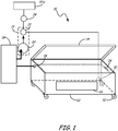
- FIG. 1 is a perspective view of a purge tank system 10.
- the purge tank system provides a controlled environment enclosure for components, such as turbine blades and vanes that are awaiting a coating process.
- the purge tank system prevents oxidation of the components.
- the purge tank system contains tank 12 with lid 14, sensor 16, controller 18, solenoid valve 21 having solenoid 20 and valve 22, and regulator 24.
- Tank 12 is constructed from aluminum or a similarly rigid material. Although illustrated as a rectangular prism, tank 12 may be of any geometry that allows for the placement and storage of the intended contents.
- tank 12 contains window 26 that is a transparent area constructed from glass or polymer. Window 12 allows for visual monitoring of the components or part (not illustrated) contained within tank 12. Window 12 may be tinted to prevent light from contacting components or parts contained within tank 12.
- Lid 14 is connected to tank 12 in a removeable or semi-removable arrangement, such as by hinges. Lid 14 is larger than the cross-sectional geometric area of the opening of tank 12 to form an enclosed area between lid 14 and tank 12. Lid 14 contains a rubber gasket that allows for creating a sealed structure with tank 12 when in the closed position. Lid 14 is constructed from the same or similar materials as tank 12, and in one embodiment, may contain a transparent area to allow for visual inspection of the contents of tank 12.
- Tank 12 may also contain an indicator level 28, such as a painted mark, protrusion, or change in geometric cross-section, that indicates the desired full capacity for the fluid level within tank 12.
- a fluid inlet 30 is contained on the lower part of tank 12 that allows for the introduction of a filling fluid into tank 12.
- the filling fluid is a typically a noble gas that is heavier than air and oxygen, such as argon, and is supplied from fluid filling source FFS through regulator 24, valve 22, solenoid 20 and fluid inlet 30 to the interior of tank 12.
- the inlet may also be on the floor of tank 12. It is preferable that fluid inlet 30 is below indicator level 28.
- Tank 12 also may contain castors 32 to allow for mobility of tank 12. This allows for the transport of components or parts within tank 12, which will keep the components within the fluid of tank 12 until just prior to removal for the coating process.
- Sensor 16 is a gas sensor.
- sensor 16 is an oxygen sensor, having an adjustable alarm range of 0-25%.
- Sensor 16 is located at the upper end of tank 12, and is meant to obtain readings from a fluid that is less dense that the filling fluid of tank, such as ambient air or oxygen.
- a fluid that is less dense that the filling fluid of tank such as ambient air or oxygen.
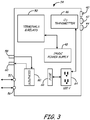
- FIG. 2 is an electrical schematic of a fluid level controller 18, and FIG. 3 is a schematic of the fluid level controller hardware.
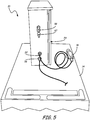
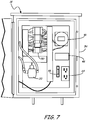
- FIGS 4-7 are various perspective views the fluid level controller 18 for purge tank system 10.
- Fluid level controller 18 has switch 40, fluid level indicator 42, fluid filling indicator 44, sensor transmitter 46, power supply 48, terminals and relays 50, and solenoid 20.
- FIG. 2 illustrates one embodiment for the electrical connections between controller 18 components, while FIGS 3-7 illustrated the hardware components associated with controller 18.
- the components are contained within panel box 54, which may be a NEMA class 1 enclosure. Box 54 contains power inlet 56 for allowing connection to a 120 VAC standard wall socket. An inlet 52 for running the electrical wiring to the sensor 16 is adjacent power inlet 56. Box 54 also contains filling fluid inlet 58 and fluid inlet 60.
- fluid level indicator 42 When the tank 12 is at a desired fill level, solenoid 20 is closed, and fluid level indicator 42 is activated. When the level of the filling fluid drops below the desired level, i.e., when sensor 16 enters the alarm state, solenoid 20 will be opened and fluid filling indicator 44 will be activated.
- fluid level indicator 42 and fluid filling indicator 44 are lights of differing colors, such as green and red respectively, that illuminate when activated. In other embodiments, fluid level indicator 42 and fluid filling indicator 44 may be different audible noises, gauges, or spring-loaded buttons.
- Power supply 48 is a 120VAC to 24DC, or similar reducer known to those of skill in the art.
- the output of power supply 48 matches that of the other components, including the terminals and relays 50, which are also known in the art.
- Box 54 also contains a 120 VAC link or outlet socket 64, and fuse 66 to protect the components from electrical fluctuations.
- Solenoid valve 21 is contained within box 54, and contains valve 22 and solenoid 20.
- Filling inlet 60 is in communication with valve 22, which is controlled by solenoid 20.
- Valve 22 is a ball valve or similar valve known to those of skill in the art.
- a second end of valve 22 is connected to a filling tank or supply of fluid such as fluid filling source via filling fluid inlet 58.
- the filling tank may contain regulator 24 to control the flow of the filling fluid from fluid filling source FFS to tank 12.
- Purge tank systems 10 monitors the level of a fluid in tank 12 at a certain level (full) and energizes and de-energizes solenoid 20, which activates valve 22, to maintain that level of fluid.
- the fluid is typically a heavy noble gas, such as argon.
- the tanks were not sealed, and the filling fluid (argon) was continuously flowed into the tank. The continuous flow was necessary to assure no ambient air was in the tank, which would allow for the oxidation of the components or parts contained therein.
- sensor 16 is a normally closed contact (see FIG. 2 ).
- coil CR1 is energized, thus closing the normally open contact for solenoid 20, which will close valve 22.
- CR1 is not energized, and the solenoid is open, and thus valve 22 is open.
- a charging of coil CR2 will close the contacts for fluid level indicator 42 and open the contact for fluid filling indicator 44, and thus switching which indicator is powered.
- Tank 12 with a sealed lid 14 prevents ambient air flow and currents from "pushing" out the argon gas. Only when an operator opens the cover to place or remove parts from the tank will some argon in the tank gets replaced by ambient air. As argon is heavier then air, it behaves like water in a bathtub.
- the sensor detects the level is below full, the sensor triggers the controller to turn on a relay to "denergize” the solenoid and allow filling gas to fill the tank.
- Sensor 16 is set to 5% alarm trip but is adjustable down to 1%.
- the system uses a normally open solenoid that is held closed when energized so that in the event of loss of power, the "purge tank” reverts back to the operation of the prior art system with constant flow to maintain the level in the tank and protect the parts with a constant flow of argon.
- the indicators, such as lights, on the unit let operators know when the system is filling and when the desired level has been reached and maintained. After the desired level has been reached, the lid may be closed. Alternately, the seal in lid 14 may allow for the expulsion of the lighter gases during the filling of tank 12, but keep out ambient air from the enclosure created by tank 12 and lid 14. In another embodiment, an outlet is provided either adjacent to or in the lid. The outlet is controlled to selectively open when tank 12 if being filled, and to close once the desired level has been reached. In one embodiment, purge tank system 10 also has a non-resetable hour meter or similar device that can accurately track usage of the filling fluid.
- the system flows argon to maintain the tank level between 54 and 60 minutes daily, down from the continuous flow of the prior art system. This time may increase or decrease depending upon the time the tank is open for the placement and retrieval of components ands parts stored therein.
- annual savings of over thirty-six thousand dollars are attributable to the purge tank system 10 from the prior art systems described.
- a method of coating a part can be accomplished with the disclosed purge tank system.
- a part is cleaned.
- the part is stored in a controlled environment enclosure, wherein the enclosure controls a fluid level of a filling fluid in the enclosure with a control system to prevent contamination of the cleaned part by sensing the level of a second fluid and adjusting the amount of filling fluid within the tank.
- the level of the filling fluid is maintained in the enclosure by the control system.
- the part is removed from the enclosure, and a coating is applied to the part.
- This coating may be either a bond coating or a plasma coating that acts as a thermal barrier coating.
- the part in the controlled environment enclosure may be stored a second time after application of a first stage of the coating process.
- the component from the controlled environment enclosure a second stage coating is applied to the component.
- the part may be moved in the controlled environment enclosure between coating stages, or from the cleaning area to the first stage coating application area.
Landscapes
- Chemical & Material Sciences (AREA)
- Life Sciences & Earth Sciences (AREA)
- Engineering & Computer Science (AREA)
- Health & Medical Sciences (AREA)
- Analytical Chemistry (AREA)
- Food Science & Technology (AREA)
- Medicinal Chemistry (AREA)
- Physics & Mathematics (AREA)
- Combustion & Propulsion (AREA)
- Biochemistry (AREA)
- General Health & Medical Sciences (AREA)
- General Physics & Mathematics (AREA)
- Immunology (AREA)
- Pathology (AREA)
- Filling Or Discharging Of Gas Storage Vessels (AREA)
- Control Of Non-Electrical Variables (AREA)
Abstract
Description
- Many components for gas turbine engines require a coating to withstand the harsh environment in which the components operate. For example, turbine blades and vanes often contain a thermal barrier coating. The coating is applied in a multistage process. First, the raw metal part is cleaned. Second, a bond coating is administered to the components to bind the outer coating to the base metal alloy. Next, a plasma coat of an outer ceramic coating is applied to the bond coating. However, the process and facilities do not necessarily allow for the immediate succession of steps in the coating process. Often, there are hours or days between the cleaning of the part, the application of the bond coating, and the application of the final outer coating. During this time, the parts must be kept clean, and must not be allowed to oxidize.
- The existing process in applying coatings to turbine components is to prevent oxidation on unfinished coated parts by submerging the parts in an unsealed purge tank, and continually flowing argon gas into the tank. However, the tank design with a continuous flow of argon is costly due to the continuous loss of argon gas because the tank is not sealed. Thus, there is a need to reduce the argon gas consumption regarding the use of the purge tank.
- A controlled environment enclosure is disclosed. The enclosure has a tank with accessible containment, and wherein the tank is capable of creating a sealed enclosure. The enclosure also has a fluid filling inlet in the tank, a fluid sensor for sensing presence of an unwanted fluid in the sealed enclosure, and a controller operatively connected to the fluid sensor for selectively allowing the filling of the enclosure through the fluid filling inlet in response to the fluid sensor sensing presence of the unwanted fluid.
- Additionally, a method of coating a part can be accomplished with the disclosed purge tank system that has the controlled environment enclosure. First, a part is cleaned. The part is stored in a controlled environment enclosure, wherein the enclosure controls a first parameter of the environment in the enclosure to prevent contamination of the cleaned part by sensing a second parameter in the tank and adjusting the environment within the tank. The environment in the enclosure is maintained by a control system. The part is removed from the enclosure, and a coating is applied to the part. This coating may be either a bond coating or a plasma coating that acts as a thermal barrier coating.
- In another embodiment, a controlled environment system that has a fluid filling source is disclosed. The system also has a tank for accessible containment of components therein, and a sensor mounted to the tank. Finally, the system has a controller that causes filling fluid to be supplied from the fluid filling source to the tank in response to the sensor sensing presence of a fluid other than the filling fluid within a controlled environment region of the tank.
- These and other features, aspects, and advantages of the present invention will become apparent from the following description, appended claims, and the accompanying exemplary embodiments shown in the drawings, which are hereafter briefly described.
- FIG. 1
- is a schematic of a purge tank system with an argon gas level controller.
- FIG. 2
- is an electrical schematic of the argon gas level controller.
- FIG. 3
- is a schematic of the argon gas level controller hardware.
- FIG. 4
- is a perspective view one embodiment of the argon gas level controller.
- FIG. 5
- is another perspective view of the argon gas level controller.
- FIG. 6
- is a front perspective of the argon gas level controller.
- FIG. 7
- is a front view of the argon gas level controller with the front cover removed.
- Efforts have been made throughout the drawings to use the same or similar reference numerals for the same or like components.
-
FIG. 1 is a perspective view of apurge tank system 10. The purge tank system provides a controlled environment enclosure for components, such as turbine blades and vanes that are awaiting a coating process. In one embodiment, the purge tank system prevents oxidation of the components. The purge tank system containstank 12 withlid 14,sensor 16,controller 18,solenoid valve 21 havingsolenoid 20 andvalve 22, andregulator 24.Tank 12 is constructed from aluminum or a similarly rigid material. Although illustrated as a rectangular prism,tank 12 may be of any geometry that allows for the placement and storage of the intended contents. In one embodiment,tank 12 containswindow 26 that is a transparent area constructed from glass or polymer. Window 12 allows for visual monitoring of the components or part (not illustrated) contained withintank 12.Window 12 may be tinted to prevent light from contacting components or parts contained withintank 12. -
Lid 14 is connected totank 12 in a removeable or semi-removable arrangement, such as by hinges.Lid 14 is larger than the cross-sectional geometric area of the opening oftank 12 to form an enclosed area betweenlid 14 andtank 12.Lid 14 contains a rubber gasket that allows for creating a sealed structure withtank 12 when in the closed position.Lid 14 is constructed from the same or similar materials astank 12, and in one embodiment, may contain a transparent area to allow for visual inspection of the contents oftank 12. -
Tank 12 may also contain anindicator level 28, such as a painted mark, protrusion, or change in geometric cross-section, that indicates the desired full capacity for the fluid level withintank 12. Afluid inlet 30 is contained on the lower part oftank 12 that allows for the introduction of a filling fluid intotank 12. The filling fluid is a typically a noble gas that is heavier than air and oxygen, such as argon, and is supplied from fluid filling source FFS throughregulator 24,valve 22,solenoid 20 andfluid inlet 30 to the interior oftank 12. Although illustrated as being on a wall, the inlet may also be on the floor oftank 12. It is preferable thatfluid inlet 30 is belowindicator level 28.Tank 12 also may containcastors 32 to allow for mobility oftank 12. This allows for the transport of components or parts withintank 12, which will keep the components within the fluid oftank 12 until just prior to removal for the coating process. -
Sensor 16 is a gas sensor. In one embodiment,sensor 16 is an oxygen sensor, having an adjustable alarm range of 0-25%.Sensor 16 is located at the upper end oftank 12, and is meant to obtain readings from a fluid that is less dense that the filling fluid of tank, such as ambient air or oxygen. Thus, when the filling fluid drops to a level below the sensor, such as when ambient air is allowed to enter the tank upon opening the lid, the sensor will enter the alarm state and trigger action of thesolenoid valve 21. -
FIG. 2 is an electrical schematic of afluid level controller 18, andFIG. 3 is a schematic of the fluid level controller hardware.FIGS 4-7 are various perspective views thefluid level controller 18 forpurge tank system 10.Fluid level controller 18 hasswitch 40,fluid level indicator 42,fluid filling indicator 44,sensor transmitter 46,power supply 48, terminals and relays 50, andsolenoid 20.FIG. 2 illustrates one embodiment for the electrical connections betweencontroller 18 components, whileFIGS 3-7 illustrated the hardware components associated withcontroller 18. The components are contained withinpanel box 54, which may be aNEMA class 1 enclosure.Box 54 containspower inlet 56 for allowing connection to a 120 VAC standard wall socket. Aninlet 52 for running the electrical wiring to thesensor 16 isadjacent power inlet 56.Box 54 also contains fillingfluid inlet 58 andfluid inlet 60. - When the
tank 12 is at a desired fill level,solenoid 20 is closed, andfluid level indicator 42 is activated. When the level of the filling fluid drops below the desired level, i.e., whensensor 16 enters the alarm state,solenoid 20 will be opened andfluid filling indicator 44 will be activated. In one embodiment,fluid level indicator 42 andfluid filling indicator 44 are lights of differing colors, such as green and red respectively, that illuminate when activated. In other embodiments,fluid level indicator 42 andfluid filling indicator 44 may be different audible noises, gauges, or spring-loaded buttons. -
Power supply 48 is a 120VAC to 24DC, or similar reducer known to those of skill in the art. The output ofpower supply 48 matches that of the other components, including the terminals and relays 50, which are also known in the art.Box 54 also contains a 120 VAC link oroutlet socket 64, and fuse 66 to protect the components from electrical fluctuations. -
Solenoid valve 21 is contained withinbox 54, and containsvalve 22 andsolenoid 20. Fillinginlet 60 is in communication withvalve 22, which is controlled bysolenoid 20.Valve 22 is a ball valve or similar valve known to those of skill in the art. A second end ofvalve 22 is connected to a filling tank or supply of fluid such as fluid filling source via fillingfluid inlet 58. The filling tank may containregulator 24 to control the flow of the filling fluid from fluid filling source FFS totank 12. -
Purge tank systems 10 monitors the level of a fluid intank 12 at a certain level (full) and energizes andde-energizes solenoid 20, which activatesvalve 22, to maintain that level of fluid. The fluid is typically a heavy noble gas, such as argon. In previous systems, the tanks were not sealed, and the filling fluid (argon) was continuously flowed into the tank. The continuous flow was necessary to assure no ambient air was in the tank, which would allow for the oxidation of the components or parts contained therein. - In operation,
sensor 16 is a normally closed contact (seeFIG. 2 ). Upon opening the contact, coil CR1 is energized, thus closing the normally open contact forsolenoid 20, which will closevalve 22. In the normally closed state ofsensor 16, CR1 is not energized, and the solenoid is open, and thusvalve 22 is open. Similarly, a charging of coil CR2 will close the contacts forfluid level indicator 42 and open the contact forfluid filling indicator 44, and thus switching which indicator is powered. -
Tank 12 with a sealedlid 14 prevents ambient air flow and currents from "pushing" out the argon gas. Only when an operator opens the cover to place or remove parts from the tank will some argon in the tank gets replaced by ambient air. As argon is heavier then air, it behaves like water in a bathtub. When the sensor detects the level is below full, the sensor triggers the controller to turn on a relay to "denergize" the solenoid and allow filling gas to fill the tank.Sensor 16 is set to 5% alarm trip but is adjustable down to 1%. The system uses a normally open solenoid that is held closed when energized so that in the event of loss of power, the "purge tank" reverts back to the operation of the prior art system with constant flow to maintain the level in the tank and protect the parts with a constant flow of argon. - The indicators, such as lights, on the unit let operators know when the system is filling and when the desired level has been reached and maintained. After the desired level has been reached, the lid may be closed. Alternately, the seal in
lid 14 may allow for the expulsion of the lighter gases during the filling oftank 12, but keep out ambient air from the enclosure created bytank 12 andlid 14. In another embodiment, an outlet is provided either adjacent to or in the lid. The outlet is controlled to selectively open whentank 12 if being filled, and to close once the desired level has been reached. In one embodiment,purge tank system 10 also has a non-resetable hour meter or similar device that can accurately track usage of the filling fluid. The system flows argon to maintain the tank level between 54 and 60 minutes daily, down from the continuous flow of the prior art system. This time may increase or decrease depending upon the time the tank is open for the placement and retrieval of components ands parts stored therein. When calculating the amount of argon gas saved by the use of the disclosed system, annual savings of over thirty-six thousand dollars are attributable to thepurge tank system 10 from the prior art systems described. - A method of coating a part can be accomplished with the disclosed purge tank system. First, a part is cleaned. The part is stored in a controlled environment enclosure, wherein the enclosure controls a fluid level of a filling fluid in the enclosure with a control system to prevent contamination of the cleaned part by sensing the level of a second fluid and adjusting the amount of filling fluid within the tank. The level of the filling fluid is maintained in the enclosure by the control system. The part is removed from the enclosure, and a coating is applied to the part. This coating may be either a bond coating or a plasma coating that acts as a thermal barrier coating.
- Additionally, the part in the controlled environment enclosure may be stored a second time after application of a first stage of the coating process. The component from the controlled environment enclosure, a second stage coating is applied to the component. The part may be moved in the controlled environment enclosure between coating stages, or from the cleaning area to the first stage coating application area.
- While the invention has been described with reference to an exemplary embodiment(s), it will be understood by those skilled in the art that various changes may be made and equivalents may be substituted for elements thereof without departing from the scope of the invention. In addition, many modifications may be made to adapt a particular situation or material to the teachings of the invention without departing from the essential scope thereof. Therefore, it is intended that the invention not be limited to the particular embodiment(s) disclosed, but that the invention will include all embodiments falling within the scope of the appended claims.
- The following clauses set out features of the invention which may not presently be claimed in this application, but which may form the basis for future amendment or a divisional application.
- 1. A controlled environment enclosure (10) comprising:
- a tank (12) with accessible containment, wherein the tank is capable of creating a sealed enclosure;
- a fluid filling inlet (30) in the tank;
- a fluid sensor (16) for sensing presence of an unwanted fluid in the sealed enclosure; and
- a controller (18) operatively connected to the fluid sensor for selectively allowing the filling of the enclosure through the fluid filling inlet in response to the fluid sensor sensing presence of the unwanted fluid.
- 2. The enclosure of
clause 1 further wherein the fluid sensor (16) is an oxygen sensor. - 3. The enclosure of
clause 1 or 2 wherein a filling fluid is introduced into the sealed enclosure, and the filling fluid is argon. - 4. The enclosure of clause 2 or clause 3 when dependent on clause 2, wherein the controller (18) allows filling of the enclosure (10) when the fluid sensor detects greater than 2% oxygen in the enclosure.
- 5. The enclosure of
clause 1, 2, 3 or 4 wherein the controller (18) further comprises a fluid level indicator (42) and a fluid filling indicator (44); and/or wherein the controller (18) further comprises a solenoid valve (21). - 6. The enclosure of any preceding clause wherein the tank (12) further comprises a lid (14) connected a main portion of the tank, and a gasket between the lid and main portion of the tank; and/or wherein the tank (12) further comprises a transparent area (26).
Claims (11)
- A method of coating a part, the method comprising:cleaning the part;storing the part in a controlled environment enclosure (10), wherein the enclosure controls a first parameter of the environment in the enclosure to prevent contamination of the cleaned part by sensing a second parameter in the tank and adjusting the environment within the tank;maintaining the environment in the enclosure;removing the part from the enclosure; andapplying a coating to the part.
- The method of claim 1, wherein applying a coating to the part comprises applying a bond coat to the part.
- The method of claim 2, further comprising:storing the part in the controlled environment enclosure (10) a second time;removing the component from the controlled environment enclosure; andapplying a plasma coating to the component.
- The method of claim 1, 2 or 3 further comprising:moving the part in the controlled environment enclosure (10) to an application area.
- The method of any preceding claim, wherein the controlled environment enclosure comprises:a fluid filling inlet (30) for introduction of a filling fluid into a tank (12), the tank comprising a hollow portion and a lid (14);a fluid sensor (16) for detecting presence of a fluid other than the filling fluid in the tank (12); anda controller (18) connected to the fluid sensor (16) and the fluid filling inlet (30) for selectively allowing the filling of the enclosure by the filling fluid through the fluid filling inlet.
- The method of claim 5, wherein the fluid sensor (16) is an oxygen sensor.
- The method of claim 5 or 6, wherein the filling fluid is argon.
- The method of any preceding claim, wherein the part is a gas turbine engine component.
- The method of claim 8, wherein the gas turbine engine component is a blade or a vane.
- The method of any preceding claim, wherein the first parameter is the amount of argon in the controlled environment enclosure (10).
- The method of any preceding claim, wherein the second parameter is the amount of oxygen in the controlled environment enclosure (10).
Applications Claiming Priority (3)
| Application Number | Priority Date | Filing Date | Title |
|---|---|---|---|
| US201161481802P | 2011-05-03 | 2011-05-03 | |
| US13/171,591 US9027609B2 (en) | 2011-05-03 | 2011-06-29 | Argon gas level controller |
| EP12166236.5A EP2520931B1 (en) | 2011-05-03 | 2012-04-30 | Argon gas level controller |
Related Parent Applications (2)
| Application Number | Title | Priority Date | Filing Date |
|---|---|---|---|
| EP12166236.5A Division EP2520931B1 (en) | 2011-05-03 | 2012-04-30 | Argon gas level controller |
| EP12166236.5A Division-Into EP2520931B1 (en) | 2011-05-03 | 2012-04-30 | Argon gas level controller |
Publications (2)
| Publication Number | Publication Date |
|---|---|
| EP3705886A1 true EP3705886A1 (en) | 2020-09-09 |
| EP3705886B1 EP3705886B1 (en) | 2023-11-22 |
Family
ID=46084841
Family Applications (2)
| Application Number | Title | Priority Date | Filing Date |
|---|---|---|---|
| EP12166236.5A Not-in-force EP2520931B1 (en) | 2011-05-03 | 2012-04-30 | Argon gas level controller |
| EP20167236.7A Active EP3705886B1 (en) | 2011-05-03 | 2012-04-30 | Method of coating a part |
Family Applications Before (1)
| Application Number | Title | Priority Date | Filing Date |
|---|---|---|---|
| EP12166236.5A Not-in-force EP2520931B1 (en) | 2011-05-03 | 2012-04-30 | Argon gas level controller |
Country Status (2)
| Country | Link |
|---|---|
| US (1) | US9027609B2 (en) |
| EP (2) | EP2520931B1 (en) |
Families Citing this family (1)
| Publication number | Priority date | Publication date | Assignee | Title |
|---|---|---|---|---|
| US20150307217A1 (en) * | 2014-04-23 | 2015-10-29 | Fresh Box LLC | Food preservation system |
Citations (2)
| Publication number | Priority date | Publication date | Assignee | Title |
|---|---|---|---|---|
| US20010042439A1 (en) * | 1996-09-13 | 2001-11-22 | Roberson Glenn A. | Molecular contamination control system |
| US20080099348A1 (en) * | 2005-01-31 | 2008-05-01 | Stuart Naylor | Apparatus and Methods for Storing Sensitive Materials |
Family Cites Families (11)
| Publication number | Priority date | Publication date | Assignee | Title |
|---|---|---|---|---|
| US4344467A (en) * | 1980-10-01 | 1982-08-17 | Lahde Frank U | Device for charging containers with an inert gas |
| DK0467668T3 (en) | 1990-07-19 | 1996-01-29 | Boc Group Plc | Storage and transport of goods under controlled atmospheres |
| AT395951B (en) | 1991-02-19 | 1993-04-26 | Union Ind Compr Gase Gmbh | CLEANING OF WORKPIECES WITH ORGANIC RESIDUES |
| US5623105A (en) * | 1992-10-21 | 1997-04-22 | Prolong Systems, Inc. | Oxygen/carbon dioxide sensor and controller for a refrigerated controlled atmosphere shipping container |
| US5799495A (en) * | 1996-10-30 | 1998-09-01 | Nitec, Inc. | Container oxygen control system for transporting and ripening perishable goods |
| EP1182272A1 (en) | 2000-08-23 | 2002-02-27 | Cold Plasma Applications C.P.A. | Process and apparatus for continuous cold plasma deposition of metallic layers |
| US6488986B2 (en) | 2001-01-29 | 2002-12-03 | General Electric Company | Combined coat, heat treat, quench method for gas turbine engine components |
| US7352464B2 (en) | 2004-01-05 | 2008-04-01 | Southwest Sciences Incorporated | Oxygen sensor for aircraft fuel inerting systems |
| US8235076B2 (en) * | 2009-02-02 | 2012-08-07 | American Air Liquide, Inc. | Method and system for optimized filling of an enclosure |
| WO2011146547A1 (en) * | 2010-05-17 | 2011-11-24 | Aeromet Technologies, Inc. | Chemical vapor deposition of metal layers for improved brazing |
| US8667977B1 (en) * | 2012-03-05 | 2014-03-11 | Oxigraf, Inc. | Oxygen sensor for tank safety |
-
2011
- 2011-06-29 US US13/171,591 patent/US9027609B2/en active Active
-
2012
- 2012-04-30 EP EP12166236.5A patent/EP2520931B1/en not_active Not-in-force
- 2012-04-30 EP EP20167236.7A patent/EP3705886B1/en active Active
Patent Citations (2)
| Publication number | Priority date | Publication date | Assignee | Title |
|---|---|---|---|---|
| US20010042439A1 (en) * | 1996-09-13 | 2001-11-22 | Roberson Glenn A. | Molecular contamination control system |
| US20080099348A1 (en) * | 2005-01-31 | 2008-05-01 | Stuart Naylor | Apparatus and Methods for Storing Sensitive Materials |
Non-Patent Citations (1)
| Title |
|---|
| TAYLOR S R ET AL: "Ion Beam Assisted Deposition of Thin Carbonaceous Films II. Adhesion Characteristics in Aqueous and Cathodically Delaminating Conditions", JOURNAL OF THE ELECTROCHEMICAL SOCIETY, vol. 135, no. 12, 1 December 1988 (1988-12-01), US, pages 2943 - 2952, XP000134305, ISSN: 0013-4651 * |
Also Published As
| Publication number | Publication date |
|---|---|
| EP2520931A2 (en) | 2012-11-07 |
| US9027609B2 (en) | 2015-05-12 |
| EP2520931B1 (en) | 2020-05-27 |
| EP2520931A3 (en) | 2014-12-10 |
| EP3705886B1 (en) | 2023-11-22 |
| US20120282416A1 (en) | 2012-11-08 |
Similar Documents
| Publication | Publication Date | Title |
|---|---|---|
| US6453759B1 (en) | Apparatus for and method of taking a predeterminable volume of a sample of medium | |
| US20180312391A1 (en) | Pneumatic operated tank filling system and related method of use | |
| US10161836B2 (en) | Pipeline sampling system and method | |
| JP2003535397A (en) | Apparatus and method for controlling liquid level | |
| CN113391037B (en) | Sample reserving device and sample reserving method for detecting chemical waste gas components | |
| EP3705886A1 (en) | Argon gas level controller | |
| CN110226091A (en) | Automatic analysis device | |
| CA3076146A1 (en) | Diesel fuel filtration and feed system for generator | |
| CN109110721A (en) | A kind of vacuum-pumping oil injection system and method for hydraulic pressure spring operating mechanism | |
| CN208329058U (en) | A kind of fire cistern with automatic checkout system | |
| RU2009119457A (en) | AUTOMATIC SYSTEM OF ANALYTICAL CONTROL OF LIQUID SAMPLES AND METHOD OF SYSTEM MANAGEMENT | |
| RU172465U1 (en) | Explosion proof type chemical dosing unit | |
| CN103407799A (en) | Material vacuum conveying system and usage method thereof | |
| CN109775170B (en) | Oil discharge port device of filling station of integrated clean system | |
| CN2509089Y (en) | Dry Powder filling machine | |
| CN113945420B (en) | Sampling mechanism and self-circulation on-line sampling device | |
| CN222700013U (en) | Quantitative loading system | |
| RU2495709C1 (en) | Automatic gas odoriser system | |
| CN114470275A (en) | a sterilizer | |
| CN121469946A (en) | A refrigeration oil dispensing device and method | |
| CN223640157U (en) | Liquid supply device and liquid supply system | |
| CN208043753U (en) | Integrated VOC Analyzer | |
| CN108502401A (en) | A kind of oil storage tank with liquid level prompting function and its liquid level based reminding method | |
| CN222559812U (en) | Truck unloading sledge type device based on crude oil medium | |
| Nguyen et al. | The Control of the Metering Valve for the Petroleum Depot Based on the Trapezoidal Flow Rate Algorithm |
Legal Events
| Date | Code | Title | Description |
|---|---|---|---|
| PUAI | Public reference made under article 153(3) epc to a published international application that has entered the european phase |
Free format text: ORIGINAL CODE: 0009012 |
|
| STAA | Information on the status of an ep patent application or granted ep patent |
Free format text: STATUS: THE APPLICATION HAS BEEN PUBLISHED |
|
| AC | Divisional application: reference to earlier application |
Ref document number: 2520931 Country of ref document: EP Kind code of ref document: P |
|
| AK | Designated contracting states |
Kind code of ref document: A1 Designated state(s): AL AT BE BG CH CY CZ DE DK EE ES FI FR GB GR HR HU IE IS IT LI LT LU LV MC MK MT NL NO PL PT RO RS SE SI SK SM TR |
|
| STAA | Information on the status of an ep patent application or granted ep patent |
Free format text: STATUS: REQUEST FOR EXAMINATION WAS MADE |
|
| RAP1 | Party data changed (applicant data changed or rights of an application transferred) |
Owner name: RAYTHEON TECHNOLOGIES CORPORATION |
|
| 17P | Request for examination filed |
Effective date: 20210309 |
|
| RBV | Designated contracting states (corrected) |
Designated state(s): AL AT BE BG CH CY CZ DE DK EE ES FI FR GB GR HR HU IE IS IT LI LT LU LV MC MK MT NL NO PL PT RO RS SE SI SK SM TR |
|
| GRAP | Despatch of communication of intention to grant a patent |
Free format text: ORIGINAL CODE: EPIDOSNIGR1 |
|
| STAA | Information on the status of an ep patent application or granted ep patent |
Free format text: STATUS: GRANT OF PATENT IS INTENDED |
|
| INTG | Intention to grant announced |
Effective date: 20221220 |
|
| GRAJ | Information related to disapproval of communication of intention to grant by the applicant or resumption of examination proceedings by the epo deleted |
Free format text: ORIGINAL CODE: EPIDOSDIGR1 |
|
| STAA | Information on the status of an ep patent application or granted ep patent |
Free format text: STATUS: REQUEST FOR EXAMINATION WAS MADE |
|
| INTC | Intention to grant announced (deleted) | ||
| GRAP | Despatch of communication of intention to grant a patent |
Free format text: ORIGINAL CODE: EPIDOSNIGR1 |
|
| STAA | Information on the status of an ep patent application or granted ep patent |
Free format text: STATUS: GRANT OF PATENT IS INTENDED |
|
| INTG | Intention to grant announced |
Effective date: 20230612 |
|
| GRAS | Grant fee paid |
Free format text: ORIGINAL CODE: EPIDOSNIGR3 |
|
| GRAA | (expected) grant |
Free format text: ORIGINAL CODE: 0009210 |
|
| STAA | Information on the status of an ep patent application or granted ep patent |
Free format text: STATUS: THE PATENT HAS BEEN GRANTED |
|
| RAP3 | Party data changed (applicant data changed or rights of an application transferred) |
Owner name: RTX CORPORATION |
|
| AC | Divisional application: reference to earlier application |
Ref document number: 2520931 Country of ref document: EP Kind code of ref document: P |
|
| AK | Designated contracting states |
Kind code of ref document: B1 Designated state(s): AL AT BE BG CH CY CZ DE DK EE ES FI FR GB GR HR HU IE IS IT LI LT LU LV MC MK MT NL NO PL PT RO RS SE SI SK SM TR |
|
| REG | Reference to a national code |
Ref country code: GB Ref legal event code: FG4D |
|
| REG | Reference to a national code |
Ref country code: CH Ref legal event code: EP |
|
| REG | Reference to a national code |
Ref country code: DE Ref legal event code: R096 Ref document number: 602012080331 Country of ref document: DE |
|
| REG | Reference to a national code |
Ref country code: IE Ref legal event code: FG4D |
|
| REG | Reference to a national code |
Ref country code: LT Ref legal event code: MG9D |
|
| REG | Reference to a national code |
Ref country code: NL Ref legal event code: MP Effective date: 20231122 |
|
| PG25 | Lapsed in a contracting state [announced via postgrant information from national office to epo] |
Ref country code: GR Free format text: LAPSE BECAUSE OF FAILURE TO SUBMIT A TRANSLATION OF THE DESCRIPTION OR TO PAY THE FEE WITHIN THE PRESCRIBED TIME-LIMIT Effective date: 20240223 |
|
| PG25 | Lapsed in a contracting state [announced via postgrant information from national office to epo] |
Ref country code: IS Free format text: LAPSE BECAUSE OF FAILURE TO SUBMIT A TRANSLATION OF THE DESCRIPTION OR TO PAY THE FEE WITHIN THE PRESCRIBED TIME-LIMIT Effective date: 20240322 |
|
| PG25 | Lapsed in a contracting state [announced via postgrant information from national office to epo] |
Ref country code: LT Free format text: LAPSE BECAUSE OF FAILURE TO SUBMIT A TRANSLATION OF THE DESCRIPTION OR TO PAY THE FEE WITHIN THE PRESCRIBED TIME-LIMIT Effective date: 20231122 |
|
| REG | Reference to a national code |
Ref country code: AT Ref legal event code: MK05 Ref document number: 1634279 Country of ref document: AT Kind code of ref document: T Effective date: 20231122 |
|
| PG25 | Lapsed in a contracting state [announced via postgrant information from national office to epo] |
Ref country code: NL Free format text: LAPSE BECAUSE OF FAILURE TO SUBMIT A TRANSLATION OF THE DESCRIPTION OR TO PAY THE FEE WITHIN THE PRESCRIBED TIME-LIMIT Effective date: 20231122 |
|
| PG25 | Lapsed in a contracting state [announced via postgrant information from national office to epo] |
Ref country code: AT Free format text: LAPSE BECAUSE OF FAILURE TO SUBMIT A TRANSLATION OF THE DESCRIPTION OR TO PAY THE FEE WITHIN THE PRESCRIBED TIME-LIMIT Effective date: 20231122 |
|
| PG25 | Lapsed in a contracting state [announced via postgrant information from national office to epo] |
Ref country code: ES Free format text: LAPSE BECAUSE OF FAILURE TO SUBMIT A TRANSLATION OF THE DESCRIPTION OR TO PAY THE FEE WITHIN THE PRESCRIBED TIME-LIMIT Effective date: 20231122 |
|
| PG25 | Lapsed in a contracting state [announced via postgrant information from national office to epo] |
Ref country code: NL Free format text: LAPSE BECAUSE OF FAILURE TO SUBMIT A TRANSLATION OF THE DESCRIPTION OR TO PAY THE FEE WITHIN THE PRESCRIBED TIME-LIMIT Effective date: 20231122 Ref country code: LT Free format text: LAPSE BECAUSE OF FAILURE TO SUBMIT A TRANSLATION OF THE DESCRIPTION OR TO PAY THE FEE WITHIN THE PRESCRIBED TIME-LIMIT Effective date: 20231122 Ref country code: IS Free format text: LAPSE BECAUSE OF FAILURE TO SUBMIT A TRANSLATION OF THE DESCRIPTION OR TO PAY THE FEE WITHIN THE PRESCRIBED TIME-LIMIT Effective date: 20240322 Ref country code: GR Free format text: LAPSE BECAUSE OF FAILURE TO SUBMIT A TRANSLATION OF THE DESCRIPTION OR TO PAY THE FEE WITHIN THE PRESCRIBED TIME-LIMIT Effective date: 20240223 Ref country code: ES Free format text: LAPSE BECAUSE OF FAILURE TO SUBMIT A TRANSLATION OF THE DESCRIPTION OR TO PAY THE FEE WITHIN THE PRESCRIBED TIME-LIMIT Effective date: 20231122 Ref country code: BG Free format text: LAPSE BECAUSE OF FAILURE TO SUBMIT A TRANSLATION OF THE DESCRIPTION OR TO PAY THE FEE WITHIN THE PRESCRIBED TIME-LIMIT Effective date: 20240222 Ref country code: AT Free format text: LAPSE BECAUSE OF FAILURE TO SUBMIT A TRANSLATION OF THE DESCRIPTION OR TO PAY THE FEE WITHIN THE PRESCRIBED TIME-LIMIT Effective date: 20231122 Ref country code: PT Free format text: LAPSE BECAUSE OF FAILURE TO SUBMIT A TRANSLATION OF THE DESCRIPTION OR TO PAY THE FEE WITHIN THE PRESCRIBED TIME-LIMIT Effective date: 20240322 |
|
| PGFP | Annual fee paid to national office [announced via postgrant information from national office to epo] |
Ref country code: GB Payment date: 20240320 Year of fee payment: 13 |
|
| PG25 | Lapsed in a contracting state [announced via postgrant information from national office to epo] |
Ref country code: SE Free format text: LAPSE BECAUSE OF FAILURE TO SUBMIT A TRANSLATION OF THE DESCRIPTION OR TO PAY THE FEE WITHIN THE PRESCRIBED TIME-LIMIT Effective date: 20231122 Ref country code: RS Free format text: LAPSE BECAUSE OF FAILURE TO SUBMIT A TRANSLATION OF THE DESCRIPTION OR TO PAY THE FEE WITHIN THE PRESCRIBED TIME-LIMIT Effective date: 20231122 Ref country code: PL Free format text: LAPSE BECAUSE OF FAILURE TO SUBMIT A TRANSLATION OF THE DESCRIPTION OR TO PAY THE FEE WITHIN THE PRESCRIBED TIME-LIMIT Effective date: 20231122 Ref country code: NO Free format text: LAPSE BECAUSE OF FAILURE TO SUBMIT A TRANSLATION OF THE DESCRIPTION OR TO PAY THE FEE WITHIN THE PRESCRIBED TIME-LIMIT Effective date: 20240222 Ref country code: LV Free format text: LAPSE BECAUSE OF FAILURE TO SUBMIT A TRANSLATION OF THE DESCRIPTION OR TO PAY THE FEE WITHIN THE PRESCRIBED TIME-LIMIT Effective date: 20231122 Ref country code: HR Free format text: LAPSE BECAUSE OF FAILURE TO SUBMIT A TRANSLATION OF THE DESCRIPTION OR TO PAY THE FEE WITHIN THE PRESCRIBED TIME-LIMIT Effective date: 20231122 |
|
| PGFP | Annual fee paid to national office [announced via postgrant information from national office to epo] |
Ref country code: FR Payment date: 20240320 Year of fee payment: 13 |
|
| PGFP | Annual fee paid to national office [announced via postgrant information from national office to epo] |
Ref country code: DE Payment date: 20240320 Year of fee payment: 13 |
|
| PG25 | Lapsed in a contracting state [announced via postgrant information from national office to epo] |
Ref country code: DK Free format text: LAPSE BECAUSE OF FAILURE TO SUBMIT A TRANSLATION OF THE DESCRIPTION OR TO PAY THE FEE WITHIN THE PRESCRIBED TIME-LIMIT Effective date: 20231122 |
|
| PG25 | Lapsed in a contracting state [announced via postgrant information from national office to epo] |
Ref country code: CZ Free format text: LAPSE BECAUSE OF FAILURE TO SUBMIT A TRANSLATION OF THE DESCRIPTION OR TO PAY THE FEE WITHIN THE PRESCRIBED TIME-LIMIT Effective date: 20231122 |
|
| PG25 | Lapsed in a contracting state [announced via postgrant information from national office to epo] |
Ref country code: SK Free format text: LAPSE BECAUSE OF FAILURE TO SUBMIT A TRANSLATION OF THE DESCRIPTION OR TO PAY THE FEE WITHIN THE PRESCRIBED TIME-LIMIT Effective date: 20231122 |
|
| PG25 | Lapsed in a contracting state [announced via postgrant information from national office to epo] |
Ref country code: SM Free format text: LAPSE BECAUSE OF FAILURE TO SUBMIT A TRANSLATION OF THE DESCRIPTION OR TO PAY THE FEE WITHIN THE PRESCRIBED TIME-LIMIT Effective date: 20231122 Ref country code: SK Free format text: LAPSE BECAUSE OF FAILURE TO SUBMIT A TRANSLATION OF THE DESCRIPTION OR TO PAY THE FEE WITHIN THE PRESCRIBED TIME-LIMIT Effective date: 20231122 Ref country code: RO Free format text: LAPSE BECAUSE OF FAILURE TO SUBMIT A TRANSLATION OF THE DESCRIPTION OR TO PAY THE FEE WITHIN THE PRESCRIBED TIME-LIMIT Effective date: 20231122 Ref country code: IT Free format text: LAPSE BECAUSE OF FAILURE TO SUBMIT A TRANSLATION OF THE DESCRIPTION OR TO PAY THE FEE WITHIN THE PRESCRIBED TIME-LIMIT Effective date: 20231122 Ref country code: EE Free format text: LAPSE BECAUSE OF FAILURE TO SUBMIT A TRANSLATION OF THE DESCRIPTION OR TO PAY THE FEE WITHIN THE PRESCRIBED TIME-LIMIT Effective date: 20231122 Ref country code: DK Free format text: LAPSE BECAUSE OF FAILURE TO SUBMIT A TRANSLATION OF THE DESCRIPTION OR TO PAY THE FEE WITHIN THE PRESCRIBED TIME-LIMIT Effective date: 20231122 Ref country code: CZ Free format text: LAPSE BECAUSE OF FAILURE TO SUBMIT A TRANSLATION OF THE DESCRIPTION OR TO PAY THE FEE WITHIN THE PRESCRIBED TIME-LIMIT Effective date: 20231122 |
|
| REG | Reference to a national code |
Ref country code: DE Ref legal event code: R097 Ref document number: 602012080331 Country of ref document: DE |
|
| PLBE | No opposition filed within time limit |
Free format text: ORIGINAL CODE: 0009261 |
|
| STAA | Information on the status of an ep patent application or granted ep patent |
Free format text: STATUS: NO OPPOSITION FILED WITHIN TIME LIMIT |
|
| PG25 | Lapsed in a contracting state [announced via postgrant information from national office to epo] |
Ref country code: SI Free format text: LAPSE BECAUSE OF FAILURE TO SUBMIT A TRANSLATION OF THE DESCRIPTION OR TO PAY THE FEE WITHIN THE PRESCRIBED TIME-LIMIT Effective date: 20231122 |
|
| 26N | No opposition filed |
Effective date: 20240823 |
|
| PG25 | Lapsed in a contracting state [announced via postgrant information from national office to epo] |
Ref country code: SI Free format text: LAPSE BECAUSE OF FAILURE TO SUBMIT A TRANSLATION OF THE DESCRIPTION OR TO PAY THE FEE WITHIN THE PRESCRIBED TIME-LIMIT Effective date: 20231122 |
|
| PG25 | Lapsed in a contracting state [announced via postgrant information from national office to epo] |
Ref country code: MC Free format text: LAPSE BECAUSE OF FAILURE TO SUBMIT A TRANSLATION OF THE DESCRIPTION OR TO PAY THE FEE WITHIN THE PRESCRIBED TIME-LIMIT Effective date: 20231122 |
|
| PG25 | Lapsed in a contracting state [announced via postgrant information from national office to epo] |
Ref country code: MC Free format text: LAPSE BECAUSE OF FAILURE TO SUBMIT A TRANSLATION OF THE DESCRIPTION OR TO PAY THE FEE WITHIN THE PRESCRIBED TIME-LIMIT Effective date: 20231122 |
|
| REG | Reference to a national code |
Ref country code: CH Ref legal event code: PL |
|
| PG25 | Lapsed in a contracting state [announced via postgrant information from national office to epo] |
Ref country code: LU Free format text: LAPSE BECAUSE OF NON-PAYMENT OF DUE FEES Effective date: 20240430 |
|
| REG | Reference to a national code |
Ref country code: BE Ref legal event code: MM Effective date: 20240430 |
|
| PG25 | Lapsed in a contracting state [announced via postgrant information from national office to epo] |
Ref country code: LU Free format text: LAPSE BECAUSE OF NON-PAYMENT OF DUE FEES Effective date: 20240430 |
|
| PG25 | Lapsed in a contracting state [announced via postgrant information from national office to epo] |
Ref country code: BE Free format text: LAPSE BECAUSE OF NON-PAYMENT OF DUE FEES Effective date: 20240430 |
|
| PG25 | Lapsed in a contracting state [announced via postgrant information from national office to epo] |
Ref country code: BE Free format text: LAPSE BECAUSE OF NON-PAYMENT OF DUE FEES Effective date: 20240430 Ref country code: CH Free format text: LAPSE BECAUSE OF NON-PAYMENT OF DUE FEES Effective date: 20240430 |
|
| PG25 | Lapsed in a contracting state [announced via postgrant information from national office to epo] |
Ref country code: IE Free format text: LAPSE BECAUSE OF NON-PAYMENT OF DUE FEES Effective date: 20240430 |
|
| PG25 | Lapsed in a contracting state [announced via postgrant information from national office to epo] |
Ref country code: CY Free format text: LAPSE BECAUSE OF FAILURE TO SUBMIT A TRANSLATION OF THE DESCRIPTION OR TO PAY THE FEE WITHIN THE PRESCRIBED TIME-LIMIT; INVALID AB INITIO Effective date: 20120430 |
|
| PG25 | Lapsed in a contracting state [announced via postgrant information from national office to epo] |
Ref country code: HU Free format text: LAPSE BECAUSE OF FAILURE TO SUBMIT A TRANSLATION OF THE DESCRIPTION OR TO PAY THE FEE WITHIN THE PRESCRIBED TIME-LIMIT; INVALID AB INITIO Effective date: 20120430 |
|
| PG25 | Lapsed in a contracting state [announced via postgrant information from national office to epo] |
Ref country code: FI Free format text: LAPSE BECAUSE OF FAILURE TO SUBMIT A TRANSLATION OF THE DESCRIPTION OR TO PAY THE FEE WITHIN THE PRESCRIBED TIME-LIMIT Effective date: 20231122 |
|
| REG | Reference to a national code |
Ref country code: DE Ref legal event code: R119 Ref document number: 602012080331 Country of ref document: DE |
|
| GBPC | Gb: european patent ceased through non-payment of renewal fee |
Effective date: 20250430 |
|
| PG25 | Lapsed in a contracting state [announced via postgrant information from national office to epo] |
Ref country code: DE Free format text: LAPSE BECAUSE OF NON-PAYMENT OF DUE FEES Effective date: 20251104 |
|
| PG25 | Lapsed in a contracting state [announced via postgrant information from national office to epo] |
Ref country code: GB Free format text: LAPSE BECAUSE OF NON-PAYMENT OF DUE FEES Effective date: 20250430 |
|
| PG25 | Lapsed in a contracting state [announced via postgrant information from national office to epo] |
Ref country code: FR Free format text: LAPSE BECAUSE OF NON-PAYMENT OF DUE FEES Effective date: 20250430 |