EP3705828B1 - Heat exchanger comprising headers with fractal geometry - Google Patents
Heat exchanger comprising headers with fractal geometry Download PDFInfo
- Publication number
- EP3705828B1 EP3705828B1 EP19216221.2A EP19216221A EP3705828B1 EP 3705828 B1 EP3705828 B1 EP 3705828B1 EP 19216221 A EP19216221 A EP 19216221A EP 3705828 B1 EP3705828 B1 EP 3705828B1
- Authority
- EP
- European Patent Office
- Prior art keywords
- header
- fluid channels
- heat exchanger
- fluid
- cross
- Prior art date
- Legal status (The legal status is an assumption and is not a legal conclusion. Google has not performed a legal analysis and makes no representation as to the accuracy of the status listed.)
- Active
Links
Images

Classifications
-
- F—MECHANICAL ENGINEERING; LIGHTING; HEATING; WEAPONS; BLASTING
- F28—HEAT EXCHANGE IN GENERAL
- F28F—DETAILS OF HEAT-EXCHANGE AND HEAT-TRANSFER APPARATUS, OF GENERAL APPLICATION
- F28F9/00—Casings; Header boxes; Auxiliary supports for elements; Auxiliary members within casings
- F28F9/02—Header boxes; End plates
- F28F9/026—Header boxes; End plates with static flow control means, e.g. with means for uniformly distributing heat exchange media into conduits
- F28F9/027—Header boxes; End plates with static flow control means, e.g. with means for uniformly distributing heat exchange media into conduits in the form of distribution pipes
- F28F9/0275—Header boxes; End plates with static flow control means, e.g. with means for uniformly distributing heat exchange media into conduits in the form of distribution pipes with multiple branch pipes
-
- F—MECHANICAL ENGINEERING; LIGHTING; HEATING; WEAPONS; BLASTING
- F28—HEAT EXCHANGE IN GENERAL
- F28D—HEAT-EXCHANGE APPARATUS, NOT PROVIDED FOR IN ANOTHER SUBCLASS, IN WHICH THE HEAT-EXCHANGE MEDIA DO NOT COME INTO DIRECT CONTACT
- F28D7/00—Heat-exchange apparatus having stationary tubular conduit assemblies for both heat-exchange media, the media being in contact with different sides of a conduit wall
- F28D7/02—Heat-exchange apparatus having stationary tubular conduit assemblies for both heat-exchange media, the media being in contact with different sides of a conduit wall the conduits being helically coiled
- F28D7/024—Heat-exchange apparatus having stationary tubular conduit assemblies for both heat-exchange media, the media being in contact with different sides of a conduit wall the conduits being helically coiled the conduits of only one medium being helically coiled tubes, the coils having a cylindrical configuration
-
- F—MECHANICAL ENGINEERING; LIGHTING; HEATING; WEAPONS; BLASTING
- F02—COMBUSTION ENGINES; HOT-GAS OR COMBUSTION-PRODUCT ENGINE PLANTS
- F02C—GAS-TURBINE PLANTS; AIR INTAKES FOR JET-PROPULSION PLANTS; CONTROLLING FUEL SUPPLY IN AIR-BREATHING JET-PROPULSION PLANTS
- F02C7/00—Features, components parts, details or accessories, not provided for in, or of interest apart form groups F02C1/00 - F02C6/00; Air intakes for jet-propulsion plants
- F02C7/12—Cooling of plants
- F02C7/14—Cooling of plants of fluids in the plant, e.g. lubricant or fuel
-
- F—MECHANICAL ENGINEERING; LIGHTING; HEATING; WEAPONS; BLASTING
- F28—HEAT EXCHANGE IN GENERAL
- F28D—HEAT-EXCHANGE APPARATUS, NOT PROVIDED FOR IN ANOTHER SUBCLASS, IN WHICH THE HEAT-EXCHANGE MEDIA DO NOT COME INTO DIRECT CONTACT
- F28D1/00—Heat-exchange apparatus having stationary conduit assemblies for one heat-exchange medium only, the media being in contact with different sides of the conduit wall, in which the other heat-exchange medium is a large body of fluid, e.g. domestic or motor car radiators
- F28D1/02—Heat-exchange apparatus having stationary conduit assemblies for one heat-exchange medium only, the media being in contact with different sides of the conduit wall, in which the other heat-exchange medium is a large body of fluid, e.g. domestic or motor car radiators with heat-exchange conduits immersed in the body of fluid
- F28D1/04—Heat-exchange apparatus having stationary conduit assemblies for one heat-exchange medium only, the media being in contact with different sides of the conduit wall, in which the other heat-exchange medium is a large body of fluid, e.g. domestic or motor car radiators with heat-exchange conduits immersed in the body of fluid with tubular conduits
- F28D1/047—Heat-exchange apparatus having stationary conduit assemblies for one heat-exchange medium only, the media being in contact with different sides of the conduit wall, in which the other heat-exchange medium is a large body of fluid, e.g. domestic or motor car radiators with heat-exchange conduits immersed in the body of fluid with tubular conduits the conduits being bent, e.g. in a serpentine or zig-zag
- F28D1/0472—Heat-exchange apparatus having stationary conduit assemblies for one heat-exchange medium only, the media being in contact with different sides of the conduit wall, in which the other heat-exchange medium is a large body of fluid, e.g. domestic or motor car radiators with heat-exchange conduits immersed in the body of fluid with tubular conduits the conduits being bent, e.g. in a serpentine or zig-zag the conduits being helically or spirally coiled
-
- F—MECHANICAL ENGINEERING; LIGHTING; HEATING; WEAPONS; BLASTING
- F05—INDEXING SCHEMES RELATING TO ENGINES OR PUMPS IN VARIOUS SUBCLASSES OF CLASSES F01-F04
- F05D—INDEXING SCHEME FOR ASPECTS RELATING TO NON-POSITIVE-DISPLACEMENT MACHINES OR ENGINES, GAS-TURBINES OR JET-PROPULSION PLANTS
- F05D2230/00—Manufacture
- F05D2230/30—Manufacture with deposition of material
- F05D2230/31—Layer deposition
-
- F—MECHANICAL ENGINEERING; LIGHTING; HEATING; WEAPONS; BLASTING
- F05—INDEXING SCHEMES RELATING TO ENGINES OR PUMPS IN VARIOUS SUBCLASSES OF CLASSES F01-F04
- F05D—INDEXING SCHEME FOR ASPECTS RELATING TO NON-POSITIVE-DISPLACEMENT MACHINES OR ENGINES, GAS-TURBINES OR JET-PROPULSION PLANTS
- F05D2260/00—Function
- F05D2260/20—Heat transfer, e.g. cooling
- F05D2260/213—Heat transfer, e.g. cooling by the provision of a heat exchanger within the cooling circuit
-
- F—MECHANICAL ENGINEERING; LIGHTING; HEATING; WEAPONS; BLASTING
- F28—HEAT EXCHANGE IN GENERAL
- F28D—HEAT-EXCHANGE APPARATUS, NOT PROVIDED FOR IN ANOTHER SUBCLASS, IN WHICH THE HEAT-EXCHANGE MEDIA DO NOT COME INTO DIRECT CONTACT
- F28D21/00—Heat-exchange apparatus not covered by any of the groups F28D1/00 - F28D20/00
- F28D2021/0019—Other heat exchangers for particular applications; Heat exchange systems not otherwise provided for
- F28D2021/0026—Other heat exchangers for particular applications; Heat exchange systems not otherwise provided for for combustion engines, e.g. for gas turbines or for Stirling engines
-
- F—MECHANICAL ENGINEERING; LIGHTING; HEATING; WEAPONS; BLASTING
- F28—HEAT EXCHANGE IN GENERAL
- F28F—DETAILS OF HEAT-EXCHANGE AND HEAT-TRANSFER APPARATUS, OF GENERAL APPLICATION
- F28F2210/00—Heat exchange conduits
- F28F2210/02—Heat exchange conduits with particular branching, e.g. fractal conduit arrangements
-
- Y—GENERAL TAGGING OF NEW TECHNOLOGICAL DEVELOPMENTS; GENERAL TAGGING OF CROSS-SECTIONAL TECHNOLOGIES SPANNING OVER SEVERAL SECTIONS OF THE IPC; TECHNICAL SUBJECTS COVERED BY FORMER USPC CROSS-REFERENCE ART COLLECTIONS [XRACs] AND DIGESTS
- Y02—TECHNOLOGIES OR APPLICATIONS FOR MITIGATION OR ADAPTATION AGAINST CLIMATE CHANGE
- Y02T—CLIMATE CHANGE MITIGATION TECHNOLOGIES RELATED TO TRANSPORTATION
- Y02T50/00—Aeronautics or air transport
- Y02T50/60—Efficient propulsion technologies, e.g. for aircraft
Definitions
- the heat exchanger includes branched tubular inlet and outlet headers with a fractal branching pattern to give the heat exchanger improved thermal and mechanical properties.
- the individual tubular flow paths can be relatively straight, while in another embodiment according to the present claimed invention, the tubular flow paths can be helical.
- the headers can be additively manufactured to achieve varied tubular dimensions (e.g., cross-sectional area, wall thicknesses, curvature, etc.), and can be mated with traditional core sections (e.g., plate-fin) or with more complex, additively manufactured core sections.
- FIG. 1 is a partial schematic view of heat exchanger 10 having a branched header 12 fluidly connected to core 14.
- Header 12 is an inlet header such that it can receive a first fluid F 1 at fluid inlet 16.
- first fluid F 1 flows through inlet header 12 and core 14 along a first flow axis A 1 and exits through an outlet header (shown in FIG. 4 ) fluidly connected to core 14 on a side opposite inlet header 12.
- the direction of flow of first fluid F 1 can be reversed such that header 12 is an outlet header with a fluid outlet 16.
- heat exchanger 10 can be arranged to receive a second fluid F 2 (not labeled in the figures) at core 14 along an axis perpendicular to axis A 1 (i.e., a cross-flow arrangement), or to receive second fluid F 2 along an axis parallel to axis A 1 in an opposite flow direction (i.e., a counter-flow arrangement).
- First fluid F 1 can be a relatively hot fluid having a higher temperature than second fluid F 2 , which can be a relatively cool fluid.
- Header 12 includes primary fluid channel 18 downstream (based on the direction of flow of fluid F 1 shown in FIG. 1 ) of inlet 16.
- a first branched region 20 is disposed downstream of primary fluid channel 18 and allows a portion of first fluid F 1 to flow into secondary fluid channels 22.
- Each of the secondary fluid channels 22 fluidly connects to a downstream second branched region 24, and each of the second branched regions 24 connects to a plurality of tertiary fluid channels 26.
- Each tertiary fluid channel 26 connects to a downstream third branched region 28, and each third branched region 28 connects to a plurality of quaternary fluid channels 30.
- Header 12 includes three branching stages stemming from primary fluid channel 18, but it could include fewer branched regions, or additional branched regions, resulting in, respectively, a reduction or increase in serially-arranged fluid channels. Further, the branched regions, as shown, are bifurcations, such that each splits into a pair of child fluid channels. Alternative headers can, however, include branched regions that subdivide into greater than two child fluid channels, based upon such factors as spatial constraints and/or desired flow characteristics, to name a few non-limiting examples.
- FIG. 2 is an enlarged view of a section of header 12 proximate second branched region 24 showing a representative geometry of the branched region and associated fluid channels.
- secondary fluid channel 22 and each tertiary fluid channel 26 are tubular (i.e., hollow with at least some rounded portions) channels having a generally circular cross-section.
- An alternative can include tubular fluid channels with one or a combination of other cross-sectional shapes, such as elliptical, oval, or shapes having rounded and/or relatively straight edges.
- cross-sectional area of a particular fluid channel can be determined using the appropriate equation.
- branching of header 12 is based upon Murray's law, which predicts the diameter of each stage of a fluid transport network for minimization of the energy cost of transport and maintenance of the transport medium.
- x can, for example, be generally equal to 3.
- radius r 2 is greater than radius r 3
- the other parent-child fluid stages of header 12 can have a similar relationship.
- the degree of adherence to Murray's law can vary from embodiment to embodiment such that x can fall within a range of approximately 1 to 3.5 or more, depending on fluid velocity, temperature, density, and tube size to name a few, non-limiting examples.
- Other factors related to header geometry, heat transfer requirements, and/or those affecting the degree of mass-conservation of a particular embodiment are also contemplated herein. Accordingly, one or more other controlling equations/principles related to fluid systems can additionally or alternatively be applied to the design of header 12.
- Heat exchanger 110 includes a core 114 fluidly connected to header 112, which is shown as an inlet header based on the direction of flow of first fluid F 1 , but can be an outlet header in an alternative embodiment.
- Header 112 has relatively straight tubes collectively giving header 112 a rectangular shape and includes fluid inlet 116 to receive first fluid F 1 .
- Header 112 is substantially similar to header 12 of FIGS.
- Header 112 further includes fourth branched regions 132 and quinary fluid channels 134. In the embodiment shown, header 112 fluidly connects to core 114 downstream of quinary fluid channels 136. Core 114 is shown with a rectangular geometry, such as a plate-fin heat exchanger.
- Heat exchanger 210 is substantially similar to heat exchangers 10 and 110, and includes a core 214 disposed between and fluidly connected to inlet header 212 I and outlet header 212 O .
- Fluid inlet 216 I to receive first fluid F 1 and outlet header 212 O includes fluid outlet 216 O through which first fluid F 1 can exit the heat exchanger.
- In serial fluid communication with each of fluid inlet 216 I and fluid outlet 216 O (denoted in FIG.
- Quaternary fluid channels 230 fluidly connect to tubular core fluid channels 238, which, are arranged to form a helical core 214.
- the branched configuration of headers 12, 112, and 212 provides increased heat transfer at the headers over traditional boxy designs, which can allow for the use of a smaller core 114, thus saving both space and weight. Further, the graduation of tube radii of the fluid channels helps alleviate turbulent flow and fluid stagnation in the headers, thus reducing pressure drop across the heat exchanger.
- the branching and tubular structure of the various fluid channels provides increased compliance (i.e., reduced stiffness) in various directions, allowing for reduced thermal stresses of the header as a whole. More specifically, the tubular fluid channels of the straight header configuration ( FIG. 3 ) act as a slim beam with reduced stiffness, while the tubular fluid channels of the helical header configuration ( FIG.
- Requisite stiffness can, however, be achieved, for example, by tailoring wall thicknesses of the tubular fluid channels, or by selecting certain geometric shapes (e.g., curved) in a desired dimension. This can drive the natural vibrational modes of the core along this dimension out of (lower) frequency bands corresponding to engine operating frequencies.
- the straight tube configuration can favor a more laminar flow due to the relatively straight fluid channels, while the helical tube configuration can favor increased heat transfer due to the ability to generate some turbulent flow through the helical fluid channels, as well as greater heat transfer area created by the increased distance between two points along the helical fluid channel.
- the headers and/or cores of heat exchangers 10, 110, and 210 can be formed partially or entirely by additive manufacturing.
- exemplary additive manufacturing processes include powder bed fusion techniques such as direct metal laser sintering (DMLS), laser net shape manufacturing (LNSM), electron beam manufacturing (EBM), to name a few, non-limiting examples.
- DMLS direct metal laser sintering
- LNSM laser net shape manufacturing
- EBM electron beam manufacturing
- SLA stereolithography
- Additive manufacturing is particularly useful in obtaining unique geometries and for reducing the need for welds or other attachments (e.g., between a header and core).
- other suitable manufacturing process can be used.
- header and core elements can in some embodiments be fabricated separately and joined via later manufacturing steps.
- the disclosed heat exchanger headers offer improved thermal and mechanical properties.
- the branching configuration reduces pressure drop across the header and allows for increased thermal transfer.
- the straight and helical tubular fluid channels give the headers increased compliance for reduced thermal stresses and can be further tailored to introduce stiffness in certain dimensions for reduced mechanical stresses.
- the disclosed headers can be used generally in other transportation industries, as well as industrial applications.
Landscapes
- Engineering & Computer Science (AREA)
- Mechanical Engineering (AREA)
- General Engineering & Computer Science (AREA)
- Physics & Mathematics (AREA)
- Thermal Sciences (AREA)
- Chemical & Material Sciences (AREA)
- Combustion & Propulsion (AREA)
- Heat-Exchange Devices With Radiators And Conduit Assemblies (AREA)
Description
- Many aircraft heat exchangers operate at high temperatures and are subject to thermal stresses caused by thermal expansion, especially with thermal coefficient mismatch and uneven temperature distribution within the heat exchanger or with abutting components. These thermal stresses can lead to a reduction in the service life of the heat exchanger. In addition, deleterious mechanical stresses due to vibration can arise where components' natural frequencies coincide significantly with engine operating frequencies. Particularly high stress regions within aircraft heat exchangers include interfaces between fluid inlets and outlets with the core section.
GB 588520 A WO 2017/052798 discloses a heat exchanger header having additively manufactured fluid channels. - Document LUO ET AL: "Experimental study of constructal distributor for flow equidistribution in a mini crossflow heat exchanger (MCHE)",CHEMICAL ENGINEERING AND PROCESSING: PROCESS INTENSIFICATION, ELSEVIER SEQUOIA, LAUSANNE, CH, vol. 47, no. 2, 12 November 2007 (2007-11-12), pages 229-236, ,ISSN: 0255-2701, discloses a heat exchanger according to the preamble of claim 1.
- According to a first aspect, there is provided a heat exchanger according to claim 1.
- [deleted]
-
-
FIG. 1 is a partial schematic view of heat exchanger with a branched header. -
FIG. 2 is an enlarged view of a branched region of the header ofFIG. 1 . -
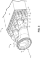
FIG. 3 is a perspective view of an embodiment not covered by the claims of the heat exchanger ofFIG. 1 having a straight tube header configuration. -
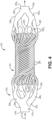
FIG. 4 is a perspective view of an alternative embodiment, according to the invention, of the heat exchanger ofFIG. 1 having a helical tube header configuration. - A heat exchanger with improved performance under thermal and vibrational stresses is disclosed herein. The heat exchanger includes branched tubular inlet and outlet headers with a fractal branching pattern to give the heat exchanger improved thermal and mechanical properties. In one embodiment not covered by the claims, the individual tubular flow paths can be relatively straight, while in another embodiment according to the present claimed invention, the tubular flow paths can be helical. The headers can be additively manufactured to achieve varied tubular dimensions (e.g., cross-sectional area, wall thicknesses, curvature, etc.), and can be mated with traditional core sections (e.g., plate-fin) or with more complex, additively manufactured core sections.
-
FIG. 1 is a partial schematic view ofheat exchanger 10 having abranched header 12 fluidly connected tocore 14.Header 12 is an inlet header such that it can receive a first fluid F1 atfluid inlet 16. In operation, first fluid F1 flows throughinlet header 12 andcore 14 along a first flow axis A1 and exits through an outlet header (shown inFIG. 4 ) fluidly connected tocore 14 on a side oppositeinlet header 12. The direction of flow of first fluid F1 can be reversed such thatheader 12 is an outlet header with afluid outlet 16. Further,heat exchanger 10 can be arranged to receive a second fluid F2 (not labeled in the figures) atcore 14 along an axis perpendicular to axis A1 (i.e., a cross-flow arrangement), or to receive second fluid F2 along an axis parallel to axis A1 in an opposite flow direction (i.e., a counter-flow arrangement). First fluid F1 can be a relatively hot fluid having a higher temperature than second fluid F2, which can be a relatively cool fluid. -
Header 12 includesprimary fluid channel 18 downstream (based on the direction of flow of fluid F1 shown inFIG. 1 ) ofinlet 16. A firstbranched region 20 is disposed downstream ofprimary fluid channel 18 and allows a portion of first fluid F1 to flow intosecondary fluid channels 22. Each of thesecondary fluid channels 22 fluidly connects to a downstream secondbranched region 24, and each of the secondbranched regions 24 connects to a plurality oftertiary fluid channels 26. Eachtertiary fluid channel 26 connects to a downstream thirdbranched region 28, and each thirdbranched region 28 connects to a plurality ofquaternary fluid channels 30.Header 12, as shown, includes three branching stages stemming fromprimary fluid channel 18, but it could include fewer branched regions, or additional branched regions, resulting in, respectively, a reduction or increase in serially-arranged fluid channels. Further, the branched regions, as shown, are bifurcations, such that each splits into a pair of child fluid channels. Alternative headers can, however, include branched regions that subdivide into greater than two child fluid channels, based upon such factors as spatial constraints and/or desired flow characteristics, to name a few non-limiting examples. -
FIG. 2 is an enlarged view of a section ofheader 12 proximate secondbranched region 24 showing a representative geometry of the branched region and associated fluid channels. InFIG. 2 ,secondary fluid channel 22 and eachtertiary fluid channel 26 are tubular (i.e., hollow with at least some rounded portions) channels having a generally circular cross-section. As shown,secondary fluid channel 22 has a radius r2 with a corresponding cross-sectional area defined by A = πr2 2. Similarly, each of thetertiary fluid channels 26 has a radius r3 and a corresponding area defined by A = πr3 2. An alternative can include tubular fluid channels with one or a combination of other cross-sectional shapes, such as elliptical, oval, or shapes having rounded and/or relatively straight edges. In such cases, cross-sectional area of a particular fluid channel can be determined using the appropriate equation. For example, the cross-sectional area of an elliptical fluid channel can be determined by A = πab, where a and b are the major and minor axes, respectively, of the ellipse. - With continued reference to
FIGS. 1 and 2 , branching ofheader 12 is based upon Murray's law, which predicts the diameter of each stage of a fluid transport network for minimization of the energy cost of transport and maintenance of the transport medium. According to Murray's law, the relationship between a parent branch and a child branch is such that rp > rd (where subscript p denotes the parent and d the child), and the relationship between a parent branch and all resulting child branches is
FIGS. 1 and 2 , radius r2 is greater than radius r3, and x can be equal to 3 (or approximately 3) such that the relationship betweensecondary fluid channel 22 andtertiary fluid channels 26 follows the equation r2 3 = Σ r3 3. The other parent-child fluid stages ofheader 12 can have a similar relationship. For example, although not depicted, primary fluid channel can have a radius r1 that is greater than radius r2, where r1 3 = Σ r2 3, and each of the quaternary fluid channels can have a radius r4 that is less than radius r3, where r33 = Σ r4 3. The degree of adherence to Murray's law can vary from embodiment to embodiment such that x can fall within a range of approximately 1 to 3.5 or more, depending on fluid velocity, temperature, density, and tube size to name a few, non-limiting examples. Other factors related to header geometry, heat transfer requirements, and/or those affecting the degree of mass-conservation of a particular embodiment are also contemplated herein. Accordingly, one or more other controlling equations/principles related to fluid systems can additionally or alternatively be applied to the design ofheader 12. - A
heat exchanger 110, not according to the invention, is shown inFIG. 3 .Heat exchanger 110 includes acore 114 fluidly connected toheader 112, which is shown as an inlet header based on the direction of flow of first fluid F1, but can be an outlet header in an alternative embodiment.Header 112 has relatively straight tubes collectively giving header 112 a rectangular shape and includesfluid inlet 116 to receive first fluid F1. Header 112 is substantially similar toheader 12 ofFIGS. 1 and 2 such that each of fluid inlet 116e is serially connected to aprimary fluid passage 118, a firstbranched region 120,secondary fluid passages 122, secondbranched regions 124,tertiary fluid channels 126, thirdbranched regions 128, andquaternary fluid channels 130.Header 112 further includes fourthbranched regions 132 andquinary fluid channels 134. In the embodiment shown,header 112 fluidly connects tocore 114 downstream of quinary fluid channels 136.Core 114 is shown with a rectangular geometry, such as a plate-fin heat exchanger. - An
alternative heat exchanger 10, according to the present invention, is shown inFIG. 4 .Heat exchanger 210, is substantially similar toheat exchangers core 214 disposed between and fluidly connected to inlet header 212I and outlet header 212O. Fluid inlet 216I to receive first fluid F1 and outlet header 212O includes fluid outlet 216O through which first fluid F1 can exit the heat exchanger. In serial fluid communication with each of fluid inlet 216I and fluid outlet 216O (denoted inFIG. 4 with the applicable "I" or "O" subscript, but generally referred to herein solely by reference number) are primary fluid passage 218, firstbranched region 220, secondary fluid passages 222, second branched regions 224,tertiary fluid channels 226, thirdbranched regions 228, and quaternary fluid channels 230. Quaternary fluid channels 230 fluidly connect to tubularcore fluid channels 238, which, are arranged to form ahelical core 214. - The branched configuration of
headers smaller core 114, thus saving both space and weight. Further, the graduation of tube radii of the fluid channels helps alleviate turbulent flow and fluid stagnation in the headers, thus reducing pressure drop across the heat exchanger. The branching and tubular structure of the various fluid channels provides increased compliance (i.e., reduced stiffness) in various directions, allowing for reduced thermal stresses of the header as a whole. More specifically, the tubular fluid channels of the straight header configuration (FIG. 3 ) act as a slim beam with reduced stiffness, while the tubular fluid channels of the helical header configuration (FIG. 4 ) act as a combination of a beam and a spring, with reduced radial and longitudinal stiffness. Requisite stiffness can, however, be achieved, for example, by tailoring wall thicknesses of the tubular fluid channels, or by selecting certain geometric shapes (e.g., curved) in a desired dimension. This can drive the natural vibrational modes of the core along this dimension out of (lower) frequency bands corresponding to engine operating frequencies. With respect to fluid flow, the straight tube configuration can favor a more laminar flow due to the relatively straight fluid channels, while the helical tube configuration can favor increased heat transfer due to the ability to generate some turbulent flow through the helical fluid channels, as well as greater heat transfer area created by the increased distance between two points along the helical fluid channel. - The headers and/or cores of
heat exchangers - The disclosed heat exchanger headers offer improved thermal and mechanical properties. The branching configuration reduces pressure drop across the header and allows for increased thermal transfer. The straight and helical tubular fluid channels give the headers increased compliance for reduced thermal stresses and can be further tailored to introduce stiffness in certain dimensions for reduced mechanical stresses. In addition to aerospace applications, the disclosed headers can be used generally in other transportation industries, as well as industrial applications.
- While the invention has been described with reference to an exemplary embodiment(s), it will be understood by those skilled in the art that various changes may be made without departing from the scope of the claims. In addition, many modifications may be made to adapt a particular situation or material to the teachings of the invention without departing from the scope of the claims. Therefore, it is intended that the invention not be limited to the particular embodiment(s) disclosed, but that the invention will include all embodiments falling within the scope of the appended claims.
Claims (7)
- A heat exchanger comprising:
a first header (212I) configured to receive a first fluid (F1) and a second header (212O) configured to output the first fluid (F1), each of the first header and second header comprising:a tubular primary fluid channel (218I,218O) oriented along a first axis and having a first cross-sectional area;a first branched region (220I,220O) adjacent to the primary fluid channel, the first branched region fluidly connected to a plurality of tubular secondary fluid channels (222I,222O), each having a second cross-sectional area; anda second branched region (224I,224O) adjacent to each of the secondary fluid channels, each of the second branched regions fluidly connected to a plurality of tubular tertiary fluid channels (226I,226O), each having a third cross-sectional area;wherein the second cross-sectional area is greater than the third cross-sectional area;wherein the first cross-sectional area is defined by a first radius, r1, the second cross-sectional area is defined by a second radius, r2, and the third cross-sectional area is defined by a third radius, r3; and characterized in that the relationship between the primary fluid channel and each of the secondary fluid channels follows the equation r1 x = Σ r2 x where x falls within the range of 1.5 to 3.5, and wherein the relationship between each of the secondary fluid channels and each of the tertiary fluid channels follows the equation r2 x = Σ r3 x where x falls within the range of 1.5 to 3.5; anda core section (214) disposed between and fluidly connecting the inlet header and the outlet header;wherein each of the secondary fluid channels (222I, 222O), the tertiary fluid channels (226I, 226O), and the core (214) have a helical geometry. - The heat exchanger of claim 1, wherein the first header (212I) and the second header (212O) have a fractal geometry.
- The heat exchanger of any preceding claim, wherein the first branched region (20) is a bifurcation, such that the plurality of secondary fluid channels comprises a pair, and wherein the second branched region (24) is a bifurcation, such that the plurality of tertiary fluid channels (26) comprises a pair.
- The heat exchanger of any preceding claim, wherein the first header and second header (212I,212O) are formed from a metallic or polymer material.
- The heat exchanger of any preceding claim, further comprising: a third branched region adj acent to each of the tertiary fluid channels (226I,226O), each of the third branched regions fluidly connected to a plurality of tubular quaternary fluid channels (230I,230O), each having a fourth cross-sectional area.
- The heat exchanger of claim 5, wherein the fourth cross-sectional area is defined by a fourth radius, r4, and wherein the relationship between each of the tertiary fluid channels and each of the quaternary fluid channels follows the equation r3 x = Σ r4 x where x falls within the range of 1.5 to 3.5.
- The heat exchanger of claim 1 or 6, wherein for each of the equations r1 x = Σ r2 x and r2 x = Σ r3 x, x = 3.
Applications Claiming Priority (1)
| Application Number | Priority Date | Filing Date | Title |
|---|---|---|---|
| US201962815831P | 2019-03-08 | 2019-03-08 |
Publications (2)
| Publication Number | Publication Date |
|---|---|
| EP3705828A1 EP3705828A1 (en) | 2020-09-09 |
| EP3705828B1 true EP3705828B1 (en) | 2023-09-13 |
Family
ID=68917389
Family Applications (1)
| Application Number | Title | Priority Date | Filing Date |
|---|---|---|---|
| EP19216221.2A Active EP3705828B1 (en) | 2019-03-08 | 2019-12-13 | Heat exchanger comprising headers with fractal geometry |
Country Status (2)
| Country | Link |
|---|---|
| US (1) | US11274886B2 (en) |
| EP (1) | EP3705828B1 (en) |
Families Citing this family (15)
| Publication number | Priority date | Publication date | Assignee | Title |
|---|---|---|---|---|
| US11660577B2 (en) * | 2017-04-21 | 2023-05-30 | Commonwealth Scientific And Industrial Research Organisation | Fractal flow distribution system |
| US11268770B2 (en) | 2019-09-06 | 2022-03-08 | Hamilton Sunstrand Corporation | Heat exchanger with radially converging manifold |
| EP3855107B1 (en) * | 2020-01-24 | 2025-07-30 | Hamilton Sundstrand Corporation | Fractal heat exchanger |
| GB2592221B (en) * | 2020-02-19 | 2022-08-24 | Reaction Engines Ltd | Heat exchanger |
| US11209222B1 (en) | 2020-08-20 | 2021-12-28 | Hamilton Sundstrand Corporation | Spiral heat exchanger header |
| WO2022197359A2 (en) * | 2021-01-21 | 2022-09-22 | Parker-Hannifin Corporation | Heat exchanger with progressive divided flow circuit, structural load bearing design |
| US11576280B2 (en) * | 2021-02-12 | 2023-02-07 | Raytheon Company | Cold plate branching flow pattern |
| US11493286B1 (en) | 2021-10-12 | 2022-11-08 | Hamilton Sundstrand Corporation | Header for high-pressure heat exchanger |
| US12209823B2 (en) * | 2022-01-21 | 2025-01-28 | Hamilton Sundstrand Corporation | Heat exchanger header structures |
| JP7738496B2 (en) * | 2022-02-04 | 2025-09-12 | 三菱重工業株式会社 | heat exchanger |
| JP7837215B2 (en) * | 2022-05-19 | 2026-03-30 | 三菱重工業株式会社 | Header member, heat exchanger unit, and method for manufacturing the header member |
| US12215938B2 (en) | 2022-12-23 | 2025-02-04 | Hamilton Sundstrand Corporation | Heat exchanger mount with internal flow passage |
| US12516893B2 (en) * | 2023-02-14 | 2026-01-06 | Hamilton Sundstrand Corporation | Heat exchangers with flow-modifying heat exchanger core tubes |
| GB202315005D0 (en) * | 2023-09-29 | 2023-11-15 | Reaction Engines Ltd | Fuel pre-heater |
| US20250146757A1 (en) * | 2023-11-03 | 2025-05-08 | Hamilton Sundstrand Corporation | Heat exchanger with stiffening tube connectors |
Family Cites Families (58)
| Publication number | Priority date | Publication date | Assignee | Title |
|---|---|---|---|---|
| US2734224A (en) * | 1956-02-14 | winstead | ||
| US485315A (en) * | 1892-11-01 | X vacuum evaporating apparatus | ||
| FR453494A (en) | 1913-01-23 | 1913-06-09 | Guglielmo Febbraro | Improvements to radiators used to cool internal combustion engines |
| BE356712A (en) | 1927-12-29 | |||
| GB588520A (en) | 1945-02-26 | 1947-05-27 | Ag Fuer Technische Studien | Improvements in tubular gas heaters |
| US3212570A (en) | 1963-08-28 | 1965-10-19 | Trane Co | Heat exchanger |
| FR2293684A2 (en) | 1974-12-05 | 1976-07-02 | Trepaud Georges | TUBULAR BEAM HEAT EXCHANGER |
| US4451960A (en) | 1979-03-15 | 1984-06-05 | Molitor Industries, Inc. | Method of producing multiple coil, multiple tube heat exchanger |
| DE3136589A1 (en) | 1981-09-15 | 1983-03-31 | Bayer Ag | TEMPERATURE STATIC MIXER AND REACTOR |
| US4570703A (en) | 1982-02-08 | 1986-02-18 | The United States Of America As Represented By The United States Department Of Energy | Tube support grid and spacer therefor |
| JPH07114250B2 (en) | 1990-04-27 | 1995-12-06 | インターナショナル・ビジネス・マシーンズ・コーポレイション | Heat transfer system |
| CA2347182C (en) | 1998-10-13 | 2004-06-15 | Biomicro Systems, Inc. | Fluid circuit components based upon passive fluid dynamics |
| DE19961257C2 (en) | 1999-12-18 | 2002-12-19 | Inst Mikrotechnik Mainz Gmbh | micromixer |
| WO2001095688A1 (en) * | 2000-06-05 | 2001-12-13 | The State Of Oregon Acting By And Through The State Board Of Higher Education On Behalf Of The University Of Oregon | Multiscale transport apparatus and methods |
| DE10141526A1 (en) | 2001-08-24 | 2003-04-17 | Zae Bayern Bayerisches Zentrum Fuer Angewandte Energieforschung Ev | Smallest amount of liquid distributor |
| US8828226B2 (en) | 2003-03-01 | 2014-09-09 | The Trustees Of Boston University | System for assessing the efficacy of stored red blood cells using microvascular networks |
| CA2443496C (en) | 2003-09-30 | 2011-10-11 | Dana Canada Corporation | Tube bundle heat exchanger comprising tubes with expanded sections |
| JP4736533B2 (en) | 2005-05-18 | 2011-07-27 | パナソニック株式会社 | Heat exchanger |
| GB0521826D0 (en) | 2005-10-26 | 2005-12-07 | Rolls Royce Plc | Wall cooling arrangement |
| KR101419682B1 (en) | 2006-08-24 | 2014-07-17 | 프레제니우스 메디칼 케어 홀딩스 인코퍼레이티드 | A device for removing fluid from a patient's blood |
| US8528628B2 (en) | 2007-02-08 | 2013-09-10 | Olantra Fund X L.L.C. | Carbon-based apparatus for cooling of electronic devices |
| US8188416B2 (en) | 2008-01-14 | 2012-05-29 | The Charles Stark Draper Laboratory, Inc. | Engineered phantoms for perfusion imaging applications |
| US20100297535A1 (en) | 2009-05-20 | 2010-11-25 | Das Susanta K | Novel design of fuel cell bipolar for optimal uniform delivery of reactant gases and efficient water removal |
| US11143636B2 (en) | 2009-05-29 | 2021-10-12 | Cytiva Sweden Ab | Fluid distributor unit |
| EP2454546B1 (en) * | 2009-07-16 | 2015-09-02 | Lockheed Martin Corporation | Helical tube bundle arrangements for heat exchangers |
| US9909783B2 (en) | 2010-02-23 | 2018-03-06 | Robert Jensen | Twisted conduit for geothermal heat exchange |
| US9134072B2 (en) | 2010-03-15 | 2015-09-15 | The Trustees Of Dartmouth College | Geometry of heat exchanger with high efficiency |
| CA2722517C (en) | 2010-11-24 | 2016-01-26 | David Wayne Mckeown | Multi-circuit manifold and method for a geothermal energy system |
| US9656212B2 (en) * | 2013-01-08 | 2017-05-23 | The Charles Stark Draper Laboratory, Inc. | Compact hydraulic manifold structure for shear sensitive fluids |
| US9964077B2 (en) | 2013-04-16 | 2018-05-08 | Kennieth Neal | Helical tube EGR cooler |
| EP3077754A1 (en) | 2013-11-19 | 2016-10-12 | Nestec S.A. | Concentric symmetrical branched heat exchanger system |
| US9976815B1 (en) | 2014-02-20 | 2018-05-22 | Hrl Laboratories, Llc | Heat exchangers made from additively manufactured sacrificial templates |
| US10995996B2 (en) | 2014-10-07 | 2021-05-04 | Unison Industries, Llc | Multi-branch furcating flow heat exchanger |
| US20160116218A1 (en) | 2014-10-27 | 2016-04-28 | Ebullient, Llc | Heat exchanger with helical passageways |
| JP5847913B1 (en) * | 2014-11-06 | 2016-01-27 | 住友精密工業株式会社 | Heat exchanger |
| US10048019B2 (en) | 2014-12-22 | 2018-08-14 | Hamilton Sundstrand Corporation | Pins for heat exchangers |
| US10495384B2 (en) | 2015-07-30 | 2019-12-03 | General Electric Company | Counter-flow heat exchanger with helical passages |
| US20170089643A1 (en) | 2015-09-25 | 2017-03-30 | Westinghouse Electric Company, Llc. | Heat Exchanger |
| US11041677B2 (en) | 2016-01-04 | 2021-06-22 | Raytheon Technologies Corporation | Heat exchanger for cooling medium temperature reduction |
| US10088250B2 (en) | 2016-01-12 | 2018-10-02 | Hamilton Sundstrand Corporation | Heat exchangers |
| US20170205149A1 (en) | 2016-01-15 | 2017-07-20 | Hamilton Sundstrand Corporation | Heat exchanger channels |
| US20180038654A1 (en) | 2016-08-08 | 2018-02-08 | General Electric Company | System for fault tolerant passage arrangements for heat exchanger applications |
| US11346611B2 (en) | 2016-08-16 | 2022-05-31 | Hamilton Sundstrand Corporation | Heat exchangers with multiple flow channels |
| EP3509842A4 (en) | 2016-09-08 | 2020-08-12 | Additive Rocket Corporation | Fractal fluid passages apparatus |
| EP3306255B1 (en) | 2016-10-07 | 2021-03-24 | Hamilton Sundstrand Corporation | Heat exchangers |
| US10655918B2 (en) | 2016-10-12 | 2020-05-19 | Baltimore Aircoil Company, Inc. | Indirect heat exchanger having circuit tubes with varying dimensions |
| DE102017203058A1 (en) | 2017-02-24 | 2018-08-30 | Fraunhofer-Gesellschaft zur Förderung der angewandten Forschung e.V. | Heat exchanger and reactor |
| US10393446B2 (en) | 2017-03-15 | 2019-08-27 | The United States Of America As Represented By The Secretary Of The Navy | Capillary heat exchanger |
| US20180283795A1 (en) | 2017-03-28 | 2018-10-04 | General Electric Company | Tubular Array Heat Exchanger |
| US10782071B2 (en) | 2017-03-28 | 2020-09-22 | General Electric Company | Tubular array heat exchanger |
| US11660577B2 (en) | 2017-04-21 | 2023-05-30 | Commonwealth Scientific And Industrial Research Organisation | Fractal flow distribution system |
| EP3410054B1 (en) | 2017-05-30 | 2022-10-26 | Ge Avio S.r.l. | Additively manufactured heat exchanger |
| US10670349B2 (en) | 2017-07-18 | 2020-06-02 | General Electric Company | Additively manufactured heat exchanger |
| US10684080B2 (en) | 2017-07-19 | 2020-06-16 | General Electric Company | Additively manufactured heat exchanger |
| WO2019060563A1 (en) | 2017-09-20 | 2019-03-28 | Additive Rocket Corporation | Additive manufacturing constructs and processes for their manufacture |
| US20200041212A1 (en) * | 2018-08-03 | 2020-02-06 | Hamilton Sundstrand Corporation | Counter flow heat exchanger |
| US11168942B2 (en) * | 2019-03-08 | 2021-11-09 | Hamilton Sundstrand Corporation | Circular core for heat exchangers |
| DE202019102083U1 (en) | 2019-04-11 | 2019-04-18 | Mahle International Gmbh | Coolant flow through corrugated fin assembly and motor vehicle component |
-
2019
- 2019-12-11 US US16/711,140 patent/US11274886B2/en active Active
- 2019-12-13 EP EP19216221.2A patent/EP3705828B1/en active Active
Non-Patent Citations (3)
| Title |
|---|
| FAN Z ET AL: "Numerical Investigation of Constructal Distributors with Different Configurations", CHINESE JOURNAL OF CHEMICAL ENGINEERING, CHEMICAL INDUSTRY PRESS, BEIJING, CN, vol. 17, no. 1, 1 February 2009 (2009-02-01), pages 175 - 178, XP026005280, ISSN: 1004-9541, [retrieved on 20090201], DOI: 10.1016/S1004-9541(09)60052-5 * |
| LUO ET AL: "Experimental study of constructal distributor for flow equidistribution in a mini crossflow heat exchanger (MCHE)", CHEMICAL ENGINEERING AND PROCESSING: PROCESS INTENSIFICATION, ELSEVIER SEQUOIA, LAUSANNE, CH, vol. 47, no. 2, 12 November 2007 (2007-11-12), pages 229 - 236, XP022339718, ISSN: 0255-2701, DOI: 10.1016/J.CEP.2007.02.028 * |
| LUO ET AL: "Integration of constructal distributors to a mini crossflow heat exchanger and their assembly configuration optimization", CHEMICAL ENGINEERING SCIENCE, OXFORD, GB, vol. 62, no. 13, 2 June 2007 (2007-06-02), pages 3605 - 3619, XP022104105, ISSN: 0009-2509 * |
Also Published As
| Publication number | Publication date |
|---|---|
| EP3705828A1 (en) | 2020-09-09 |
| US11274886B2 (en) | 2022-03-15 |
| US20200284532A1 (en) | 2020-09-10 |
Similar Documents
| Publication | Publication Date | Title |
|---|---|---|
| US11274886B2 (en) | Heat exchanger header with fractal geometry | |
| EP3705830B1 (en) | Circular core for heat exchangers | |
| EP3699537B1 (en) | Leaf-shaped geometry for heat exchanger core | |
| EP3705826B1 (en) | Radially layered helical core geometry for heat exchanger | |
| US10584922B2 (en) | Heat exchanges with installation flexibility | |
| EP3124906B1 (en) | Counter-flow heat exchanger with helical passages | |
| US12130090B2 (en) | Heat exchanger with radially converging manifold | |
| EP3705831B1 (en) | Rectangular helical core geometry for heat exchanger | |
| EP3957943B1 (en) | Spiral heat exchanger header | |
| EP3073217B1 (en) | Heat exchanger for a gas turbine engine | |
| EP3800417A1 (en) | Heat exchanger with interleaved manifolds and layered core | |
| EP3825638B1 (en) | Integrated horn structures for heat exchanger headers | |
| EP3604998A1 (en) | Counter flow heat exchanger | |
| EP3705829B1 (en) | Heat exchanger | |
| US12013190B2 (en) | Wavy adjacent passage heat exchanger core and manifold | |
| EP3892949A2 (en) | Aircraft heat exchangers and plates | |
| EP4166888B1 (en) | Header for high-pressure heat exchanger | |
| EP3705827A1 (en) | Cyllindrical helical core geometry for heat exchanger | |
| US11982499B2 (en) | Heat exchanger with heat transfer augmentation features | |
| US20220412658A1 (en) | Wavy adjacent passage heat exchanger core |
Legal Events
| Date | Code | Title | Description |
|---|---|---|---|
| PUAI | Public reference made under article 153(3) epc to a published international application that has entered the european phase |
Free format text: ORIGINAL CODE: 0009012 |
|
| STAA | Information on the status of an ep patent application or granted ep patent |
Free format text: STATUS: THE APPLICATION HAS BEEN PUBLISHED |
|
| AK | Designated contracting states |
Kind code of ref document: A1 Designated state(s): AL AT BE BG CH CY CZ DE DK EE ES FI FR GB GR HR HU IE IS IT LI LT LU LV MC MK MT NL NO PL PT RO RS SE SI SK SM TR |
|
| AX | Request for extension of the european patent |
Extension state: BA ME |
|
| STAA | Information on the status of an ep patent application or granted ep patent |
Free format text: STATUS: REQUEST FOR EXAMINATION WAS MADE |
|
| 17P | Request for examination filed |
Effective date: 20201021 |
|
| RBV | Designated contracting states (corrected) |
Designated state(s): AL AT BE BG CH CY CZ DE DK EE ES FI FR GB GR HR HU IE IS IT LI LT LU LV MC MK MT NL NO PL PT RO RS SE SI SK SM TR |
|
| STAA | Information on the status of an ep patent application or granted ep patent |
Free format text: STATUS: EXAMINATION IS IN PROGRESS |
|
| 17Q | First examination report despatched |
Effective date: 20211027 |
|
| GRAP | Despatch of communication of intention to grant a patent |
Free format text: ORIGINAL CODE: EPIDOSNIGR1 |
|
| STAA | Information on the status of an ep patent application or granted ep patent |
Free format text: STATUS: GRANT OF PATENT IS INTENDED |
|
| INTG | Intention to grant announced |
Effective date: 20230413 |
|
| RIN1 | Information on inventor provided before grant (corrected) |
Inventor name: JOSEPH, EPHRAIM Inventor name: HU, MICHELE Inventor name: DOE, MICHAEL Inventor name: MAYNARD, MICHAEL Inventor name: FENG, FENG Inventor name: RUIZ, GABRIEL Inventor name: BECENE, AHMET T. |
|
| GRAS | Grant fee paid |
Free format text: ORIGINAL CODE: EPIDOSNIGR3 |
|
| GRAA | (expected) grant |
Free format text: ORIGINAL CODE: 0009210 |
|
| STAA | Information on the status of an ep patent application or granted ep patent |
Free format text: STATUS: THE PATENT HAS BEEN GRANTED |
|
| AK | Designated contracting states |
Kind code of ref document: B1 Designated state(s): AL AT BE BG CH CY CZ DE DK EE ES FI FR GB GR HR HU IE IS IT LI LT LU LV MC MK MT NL NO PL PT RO RS SE SI SK SM TR |
|
| REG | Reference to a national code |
Ref country code: CH Ref legal event code: EP |
|
| REG | Reference to a national code |
Ref country code: DE Ref legal event code: R096 Ref document number: 602019037274 Country of ref document: DE |
|
| REG | Reference to a national code |
Ref country code: IE Ref legal event code: FG4D |
|
| REG | Reference to a national code |
Ref country code: LT Ref legal event code: MG9D |
|
| REG | Reference to a national code |
Ref country code: NL Ref legal event code: MP Effective date: 20230913 |
|
| PG25 | Lapsed in a contracting state [announced via postgrant information from national office to epo] |
Ref country code: GR Free format text: LAPSE BECAUSE OF FAILURE TO SUBMIT A TRANSLATION OF THE DESCRIPTION OR TO PAY THE FEE WITHIN THE PRESCRIBED TIME-LIMIT Effective date: 20231214 |
|
| PG25 | Lapsed in a contracting state [announced via postgrant information from national office to epo] |
Ref country code: SE Free format text: LAPSE BECAUSE OF FAILURE TO SUBMIT A TRANSLATION OF THE DESCRIPTION OR TO PAY THE FEE WITHIN THE PRESCRIBED TIME-LIMIT Effective date: 20230913 Ref country code: RS Free format text: LAPSE BECAUSE OF FAILURE TO SUBMIT A TRANSLATION OF THE DESCRIPTION OR TO PAY THE FEE WITHIN THE PRESCRIBED TIME-LIMIT Effective date: 20230913 Ref country code: NO Free format text: LAPSE BECAUSE OF FAILURE TO SUBMIT A TRANSLATION OF THE DESCRIPTION OR TO PAY THE FEE WITHIN THE PRESCRIBED TIME-LIMIT Effective date: 20231213 Ref country code: LV Free format text: LAPSE BECAUSE OF FAILURE TO SUBMIT A TRANSLATION OF THE DESCRIPTION OR TO PAY THE FEE WITHIN THE PRESCRIBED TIME-LIMIT Effective date: 20230913 Ref country code: LT Free format text: LAPSE BECAUSE OF FAILURE TO SUBMIT A TRANSLATION OF THE DESCRIPTION OR TO PAY THE FEE WITHIN THE PRESCRIBED TIME-LIMIT Effective date: 20230913 Ref country code: HR Free format text: LAPSE BECAUSE OF FAILURE TO SUBMIT A TRANSLATION OF THE DESCRIPTION OR TO PAY THE FEE WITHIN THE PRESCRIBED TIME-LIMIT Effective date: 20230913 Ref country code: GR Free format text: LAPSE BECAUSE OF FAILURE TO SUBMIT A TRANSLATION OF THE DESCRIPTION OR TO PAY THE FEE WITHIN THE PRESCRIBED TIME-LIMIT Effective date: 20231214 Ref country code: FI Free format text: LAPSE BECAUSE OF FAILURE TO SUBMIT A TRANSLATION OF THE DESCRIPTION OR TO PAY THE FEE WITHIN THE PRESCRIBED TIME-LIMIT Effective date: 20230913 |
|
| REG | Reference to a national code |
Ref country code: AT Ref legal event code: MK05 Ref document number: 1611677 Country of ref document: AT Kind code of ref document: T Effective date: 20230913 |
|
| PG25 | Lapsed in a contracting state [announced via postgrant information from national office to epo] |
Ref country code: NL Free format text: LAPSE BECAUSE OF FAILURE TO SUBMIT A TRANSLATION OF THE DESCRIPTION OR TO PAY THE FEE WITHIN THE PRESCRIBED TIME-LIMIT Effective date: 20230913 |
|
| PG25 | Lapsed in a contracting state [announced via postgrant information from national office to epo] |
Ref country code: IS Free format text: LAPSE BECAUSE OF FAILURE TO SUBMIT A TRANSLATION OF THE DESCRIPTION OR TO PAY THE FEE WITHIN THE PRESCRIBED TIME-LIMIT Effective date: 20240113 |
|
| PG25 | Lapsed in a contracting state [announced via postgrant information from national office to epo] |
Ref country code: AT Free format text: LAPSE BECAUSE OF FAILURE TO SUBMIT A TRANSLATION OF THE DESCRIPTION OR TO PAY THE FEE WITHIN THE PRESCRIBED TIME-LIMIT Effective date: 20230913 |
|
| PG25 | Lapsed in a contracting state [announced via postgrant information from national office to epo] |
Ref country code: ES Free format text: LAPSE BECAUSE OF FAILURE TO SUBMIT A TRANSLATION OF THE DESCRIPTION OR TO PAY THE FEE WITHIN THE PRESCRIBED TIME-LIMIT Effective date: 20230913 |
|
| PG25 | Lapsed in a contracting state [announced via postgrant information from national office to epo] |
Ref country code: SM Free format text: LAPSE BECAUSE OF FAILURE TO SUBMIT A TRANSLATION OF THE DESCRIPTION OR TO PAY THE FEE WITHIN THE PRESCRIBED TIME-LIMIT Effective date: 20230913 Ref country code: RO Free format text: LAPSE BECAUSE OF FAILURE TO SUBMIT A TRANSLATION OF THE DESCRIPTION OR TO PAY THE FEE WITHIN THE PRESCRIBED TIME-LIMIT Effective date: 20230913 Ref country code: IS Free format text: LAPSE BECAUSE OF FAILURE TO SUBMIT A TRANSLATION OF THE DESCRIPTION OR TO PAY THE FEE WITHIN THE PRESCRIBED TIME-LIMIT Effective date: 20240113 Ref country code: ES Free format text: LAPSE BECAUSE OF FAILURE TO SUBMIT A TRANSLATION OF THE DESCRIPTION OR TO PAY THE FEE WITHIN THE PRESCRIBED TIME-LIMIT Effective date: 20230913 Ref country code: EE Free format text: LAPSE BECAUSE OF FAILURE TO SUBMIT A TRANSLATION OF THE DESCRIPTION OR TO PAY THE FEE WITHIN THE PRESCRIBED TIME-LIMIT Effective date: 20230913 Ref country code: CZ Free format text: LAPSE BECAUSE OF FAILURE TO SUBMIT A TRANSLATION OF THE DESCRIPTION OR TO PAY THE FEE WITHIN THE PRESCRIBED TIME-LIMIT Effective date: 20230913 Ref country code: AT Free format text: LAPSE BECAUSE OF FAILURE TO SUBMIT A TRANSLATION OF THE DESCRIPTION OR TO PAY THE FEE WITHIN THE PRESCRIBED TIME-LIMIT Effective date: 20230913 Ref country code: PT Free format text: LAPSE BECAUSE OF FAILURE TO SUBMIT A TRANSLATION OF THE DESCRIPTION OR TO PAY THE FEE WITHIN THE PRESCRIBED TIME-LIMIT Effective date: 20240115 Ref country code: SK Free format text: LAPSE BECAUSE OF FAILURE TO SUBMIT A TRANSLATION OF THE DESCRIPTION OR TO PAY THE FEE WITHIN THE PRESCRIBED TIME-LIMIT Effective date: 20230913 |
|
| PG25 | Lapsed in a contracting state [announced via postgrant information from national office to epo] |
Ref country code: PL Free format text: LAPSE BECAUSE OF FAILURE TO SUBMIT A TRANSLATION OF THE DESCRIPTION OR TO PAY THE FEE WITHIN THE PRESCRIBED TIME-LIMIT Effective date: 20230913 Ref country code: IT Free format text: LAPSE BECAUSE OF FAILURE TO SUBMIT A TRANSLATION OF THE DESCRIPTION OR TO PAY THE FEE WITHIN THE PRESCRIBED TIME-LIMIT Effective date: 20230913 |
|
| REG | Reference to a national code |
Ref country code: DE Ref legal event code: R097 Ref document number: 602019037274 Country of ref document: DE |
|
| PG25 | Lapsed in a contracting state [announced via postgrant information from national office to epo] |
Ref country code: DK Free format text: LAPSE BECAUSE OF FAILURE TO SUBMIT A TRANSLATION OF THE DESCRIPTION OR TO PAY THE FEE WITHIN THE PRESCRIBED TIME-LIMIT Effective date: 20230913 |
|
| PLBE | No opposition filed within time limit |
Free format text: ORIGINAL CODE: 0009261 |
|
| STAA | Information on the status of an ep patent application or granted ep patent |
Free format text: STATUS: NO OPPOSITION FILED WITHIN TIME LIMIT |
|
| PG25 | Lapsed in a contracting state [announced via postgrant information from national office to epo] |
Ref country code: DK Free format text: LAPSE BECAUSE OF FAILURE TO SUBMIT A TRANSLATION OF THE DESCRIPTION OR TO PAY THE FEE WITHIN THE PRESCRIBED TIME-LIMIT Effective date: 20230913 |
|
| REG | Reference to a national code |
Ref country code: CH Ref legal event code: PL |
|
| 26N | No opposition filed |
Effective date: 20240614 |
|
| PG25 | Lapsed in a contracting state [announced via postgrant information from national office to epo] |
Ref country code: LU Free format text: LAPSE BECAUSE OF NON-PAYMENT OF DUE FEES Effective date: 20231213 |
|
| PG25 | Lapsed in a contracting state [announced via postgrant information from national office to epo] |
Ref country code: MC Free format text: LAPSE BECAUSE OF FAILURE TO SUBMIT A TRANSLATION OF THE DESCRIPTION OR TO PAY THE FEE WITHIN THE PRESCRIBED TIME-LIMIT Effective date: 20230913 |
|
| REG | Reference to a national code |
Ref country code: BE Ref legal event code: MM Effective date: 20231231 |
|
| PG25 | Lapsed in a contracting state [announced via postgrant information from national office to epo] |
Ref country code: MC Free format text: LAPSE BECAUSE OF FAILURE TO SUBMIT A TRANSLATION OF THE DESCRIPTION OR TO PAY THE FEE WITHIN THE PRESCRIBED TIME-LIMIT Effective date: 20230913 Ref country code: LU Free format text: LAPSE BECAUSE OF NON-PAYMENT OF DUE FEES Effective date: 20231213 |
|
| REG | Reference to a national code |
Ref country code: IE Ref legal event code: MM4A |
|
| PG25 | Lapsed in a contracting state [announced via postgrant information from national office to epo] |
Ref country code: IE Free format text: LAPSE BECAUSE OF NON-PAYMENT OF DUE FEES Effective date: 20231213 |
|
| PG25 | Lapsed in a contracting state [announced via postgrant information from national office to epo] |
Ref country code: BE Free format text: LAPSE BECAUSE OF NON-PAYMENT OF DUE FEES Effective date: 20231231 |
|
| PG25 | Lapsed in a contracting state [announced via postgrant information from national office to epo] |
Ref country code: CH Free format text: LAPSE BECAUSE OF NON-PAYMENT OF DUE FEES Effective date: 20231231 |
|
| PG25 | Lapsed in a contracting state [announced via postgrant information from national office to epo] |
Ref country code: SI Free format text: LAPSE BECAUSE OF FAILURE TO SUBMIT A TRANSLATION OF THE DESCRIPTION OR TO PAY THE FEE WITHIN THE PRESCRIBED TIME-LIMIT Effective date: 20230913 |
|
| PG25 | Lapsed in a contracting state [announced via postgrant information from national office to epo] |
Ref country code: SI Free format text: LAPSE BECAUSE OF FAILURE TO SUBMIT A TRANSLATION OF THE DESCRIPTION OR TO PAY THE FEE WITHIN THE PRESCRIBED TIME-LIMIT Effective date: 20230913 Ref country code: IE Free format text: LAPSE BECAUSE OF NON-PAYMENT OF DUE FEES Effective date: 20231213 Ref country code: CH Free format text: LAPSE BECAUSE OF NON-PAYMENT OF DUE FEES Effective date: 20231231 Ref country code: BE Free format text: LAPSE BECAUSE OF NON-PAYMENT OF DUE FEES Effective date: 20231231 |
|
| PG25 | Lapsed in a contracting state [announced via postgrant information from national office to epo] |
Ref country code: BG Free format text: LAPSE BECAUSE OF FAILURE TO SUBMIT A TRANSLATION OF THE DESCRIPTION OR TO PAY THE FEE WITHIN THE PRESCRIBED TIME-LIMIT Effective date: 20230913 |
|
| PG25 | Lapsed in a contracting state [announced via postgrant information from national office to epo] |
Ref country code: BG Free format text: LAPSE BECAUSE OF FAILURE TO SUBMIT A TRANSLATION OF THE DESCRIPTION OR TO PAY THE FEE WITHIN THE PRESCRIBED TIME-LIMIT Effective date: 20230913 |
|
| PG25 | Lapsed in a contracting state [announced via postgrant information from national office to epo] |
Ref country code: CY Free format text: LAPSE BECAUSE OF FAILURE TO SUBMIT A TRANSLATION OF THE DESCRIPTION OR TO PAY THE FEE WITHIN THE PRESCRIBED TIME-LIMIT; INVALID AB INITIO Effective date: 20191213 |
|
| PG25 | Lapsed in a contracting state [announced via postgrant information from national office to epo] |
Ref country code: HU Free format text: LAPSE BECAUSE OF FAILURE TO SUBMIT A TRANSLATION OF THE DESCRIPTION OR TO PAY THE FEE WITHIN THE PRESCRIBED TIME-LIMIT; INVALID AB INITIO Effective date: 20191213 |
|
| PG25 | Lapsed in a contracting state [announced via postgrant information from national office to epo] |
Ref country code: TR Free format text: LAPSE BECAUSE OF FAILURE TO SUBMIT A TRANSLATION OF THE DESCRIPTION OR TO PAY THE FEE WITHIN THE PRESCRIBED TIME-LIMIT Effective date: 20230913 |
|
| PGFP | Annual fee paid to national office [announced via postgrant information from national office to epo] |
Ref country code: DE Payment date: 20251126 Year of fee payment: 7 |
|
| PGFP | Annual fee paid to national office [announced via postgrant information from national office to epo] |
Ref country code: GB Payment date: 20251120 Year of fee payment: 7 |
|
| PGFP | Annual fee paid to national office [announced via postgrant information from national office to epo] |
Ref country code: FR Payment date: 20251120 Year of fee payment: 7 |
|
| P01 | Opt-out of the competence of the unified patent court (upc) registered |
Free format text: CASE NUMBER: UPC_APP_0018968_3705828/2025 Effective date: 20251222 |