EP3705759B1 - Actively controlled contacting seal - Google Patents
Actively controlled contacting seal Download PDFInfo
- Publication number
- EP3705759B1 EP3705759B1 EP19219626.9A EP19219626A EP3705759B1 EP 3705759 B1 EP3705759 B1 EP 3705759B1 EP 19219626 A EP19219626 A EP 19219626A EP 3705759 B1 EP3705759 B1 EP 3705759B1
- Authority
- EP
- European Patent Office
- Prior art keywords
- seal
- ramp
- follower
- seal element
- interface surface
- Prior art date
- Legal status (The legal status is an assumption and is not a legal conclusion. Google has not performed a legal analysis and makes no representation as to the accuracy of the status listed.)
- Active
Links
Images

Classifications
-
- F—MECHANICAL ENGINEERING; LIGHTING; HEATING; WEAPONS; BLASTING
- F16—ENGINEERING ELEMENTS AND UNITS; GENERAL MEASURES FOR PRODUCING AND MAINTAINING EFFECTIVE FUNCTIONING OF MACHINES OR INSTALLATIONS; THERMAL INSULATION IN GENERAL
- F16J—PISTONS; CYLINDERS; SEALINGS
- F16J15/00—Sealings
- F16J15/16—Sealings between relatively-moving surfaces
- F16J15/34—Sealings between relatively-moving surfaces with slip-ring pressed against a more or less radial face on one member
- F16J15/3436—Pressing means
- F16J15/346—Pressing means the pressing force varying during operation
-
- F—MECHANICAL ENGINEERING; LIGHTING; HEATING; WEAPONS; BLASTING
- F02—COMBUSTION ENGINES; HOT-GAS OR COMBUSTION-PRODUCT ENGINE PLANTS
- F02C—GAS-TURBINE PLANTS; AIR INTAKES FOR JET-PROPULSION PLANTS; CONTROLLING FUEL SUPPLY IN AIR-BREATHING JET-PROPULSION PLANTS
- F02C7/00—Features, components parts, details or accessories, not provided for in, or of interest apart form groups F02C1/00 - F02C6/00; Air intakes for jet-propulsion plants
- F02C7/06—Arrangements of bearings; Lubricating
-
- F—MECHANICAL ENGINEERING; LIGHTING; HEATING; WEAPONS; BLASTING
- F01—MACHINES OR ENGINES IN GENERAL; ENGINE PLANTS IN GENERAL; STEAM ENGINES
- F01D—NON-POSITIVE DISPLACEMENT MACHINES OR ENGINES, e.g. STEAM TURBINES
- F01D11/00—Preventing or minimising internal leakage of working-fluid, e.g. between stages
- F01D11/003—Preventing or minimising internal leakage of working-fluid, e.g. between stages by packing rings; Mechanical seals
-
- F—MECHANICAL ENGINEERING; LIGHTING; HEATING; WEAPONS; BLASTING
- F01—MACHINES OR ENGINES IN GENERAL; ENGINE PLANTS IN GENERAL; STEAM ENGINES
- F01D—NON-POSITIVE DISPLACEMENT MACHINES OR ENGINES, e.g. STEAM TURBINES
- F01D25/00—Component parts, details, or accessories, not provided for in, or of interest apart from, other groups
- F01D25/18—Lubricating arrangements
- F01D25/183—Sealing means
-
- F—MECHANICAL ENGINEERING; LIGHTING; HEATING; WEAPONS; BLASTING
- F16—ENGINEERING ELEMENTS AND UNITS; GENERAL MEASURES FOR PRODUCING AND MAINTAINING EFFECTIVE FUNCTIONING OF MACHINES OR INSTALLATIONS; THERMAL INSULATION IN GENERAL
- F16J—PISTONS; CYLINDERS; SEALINGS
- F16J15/00—Sealings
- F16J15/16—Sealings between relatively-moving surfaces
- F16J15/162—Special parts or details relating to lubrication or cooling of the sealing itself
-
- F—MECHANICAL ENGINEERING; LIGHTING; HEATING; WEAPONS; BLASTING
- F16—ENGINEERING ELEMENTS AND UNITS; GENERAL MEASURES FOR PRODUCING AND MAINTAINING EFFECTIVE FUNCTIONING OF MACHINES OR INSTALLATIONS; THERMAL INSULATION IN GENERAL
- F16J—PISTONS; CYLINDERS; SEALINGS
- F16J15/00—Sealings
- F16J15/16—Sealings between relatively-moving surfaces
- F16J15/164—Sealings between relatively-moving surfaces the sealing action depending on movements; pressure difference, temperature or presence of leaking fluid
-
- F—MECHANICAL ENGINEERING; LIGHTING; HEATING; WEAPONS; BLASTING
- F16—ENGINEERING ELEMENTS AND UNITS; GENERAL MEASURES FOR PRODUCING AND MAINTAINING EFFECTIVE FUNCTIONING OF MACHINES OR INSTALLATIONS; THERMAL INSULATION IN GENERAL
- F16J—PISTONS; CYLINDERS; SEALINGS
- F16J15/00—Sealings
- F16J15/16—Sealings between relatively-moving surfaces
- F16J15/34—Sealings between relatively-moving surfaces with slip-ring pressed against a more or less radial face on one member
- F16J15/3404—Sealings between relatively-moving surfaces with slip-ring pressed against a more or less radial face on one member and characterised by parts or details relating to lubrication, cooling or venting of the seal
- F16J15/3408—Sealings between relatively-moving surfaces with slip-ring pressed against a more or less radial face on one member and characterised by parts or details relating to lubrication, cooling or venting of the seal at least one ring having an uneven slipping surface
- F16J15/3412—Sealings between relatively-moving surfaces with slip-ring pressed against a more or less radial face on one member and characterised by parts or details relating to lubrication, cooling or venting of the seal at least one ring having an uneven slipping surface with cavities
- F16J15/342—Sealings between relatively-moving surfaces with slip-ring pressed against a more or less radial face on one member and characterised by parts or details relating to lubrication, cooling or venting of the seal at least one ring having an uneven slipping surface with cavities with means for feeding fluid directly to the face
-
- F—MECHANICAL ENGINEERING; LIGHTING; HEATING; WEAPONS; BLASTING
- F16—ENGINEERING ELEMENTS AND UNITS; GENERAL MEASURES FOR PRODUCING AND MAINTAINING EFFECTIVE FUNCTIONING OF MACHINES OR INSTALLATIONS; THERMAL INSULATION IN GENERAL
- F16J—PISTONS; CYLINDERS; SEALINGS
- F16J15/00—Sealings
- F16J15/16—Sealings between relatively-moving surfaces
- F16J15/34—Sealings between relatively-moving surfaces with slip-ring pressed against a more or less radial face on one member
- F16J15/3492—Sealings between relatively-moving surfaces with slip-ring pressed against a more or less radial face on one member with monitoring or measuring means associated with the seal
-
- F—MECHANICAL ENGINEERING; LIGHTING; HEATING; WEAPONS; BLASTING
- F05—INDEXING SCHEMES RELATING TO ENGINES OR PUMPS IN VARIOUS SUBCLASSES OF CLASSES F01-F04
- F05D—INDEXING SCHEME FOR ASPECTS RELATING TO NON-POSITIVE-DISPLACEMENT MACHINES OR ENGINES, GAS-TURBINES OR JET-PROPULSION PLANTS
- F05D2240/00—Components
- F05D2240/55—Seals
-
- F—MECHANICAL ENGINEERING; LIGHTING; HEATING; WEAPONS; BLASTING
- F05—INDEXING SCHEMES RELATING TO ENGINES OR PUMPS IN VARIOUS SUBCLASSES OF CLASSES F01-F04
- F05D—INDEXING SCHEME FOR ASPECTS RELATING TO NON-POSITIVE-DISPLACEMENT MACHINES OR ENGINES, GAS-TURBINES OR JET-PROPULSION PLANTS
- F05D2260/00—Function
- F05D2260/30—Retaining components in desired mutual position
- F05D2260/38—Retaining components in desired mutual position by a spring, i.e. spring loaded or biased towards a certain position
-
- F—MECHANICAL ENGINEERING; LIGHTING; HEATING; WEAPONS; BLASTING
- F05—INDEXING SCHEMES RELATING TO ENGINES OR PUMPS IN VARIOUS SUBCLASSES OF CLASSES F01-F04
- F05D—INDEXING SCHEME FOR ASPECTS RELATING TO NON-POSITIVE-DISPLACEMENT MACHINES OR ENGINES, GAS-TURBINES OR JET-PROPULSION PLANTS
- F05D2260/00—Function
- F05D2260/40—Transmission of power
- F05D2260/403—Transmission of power through the shape of the drive components
- F05D2260/4031—Transmission of power through the shape of the drive components as in toothed gearing
-
- F—MECHANICAL ENGINEERING; LIGHTING; HEATING; WEAPONS; BLASTING
- F05—INDEXING SCHEMES RELATING TO ENGINES OR PUMPS IN VARIOUS SUBCLASSES OF CLASSES F01-F04
- F05D—INDEXING SCHEME FOR ASPECTS RELATING TO NON-POSITIVE-DISPLACEMENT MACHINES OR ENGINES, GAS-TURBINES OR JET-PROPULSION PLANTS
- F05D2270/00—Control
- F05D2270/40—Type of control system
- F05D2270/44—Type of control system active, predictive, or anticipative
-
- F—MECHANICAL ENGINEERING; LIGHTING; HEATING; WEAPONS; BLASTING
- F05—INDEXING SCHEMES RELATING TO ENGINES OR PUMPS IN VARIOUS SUBCLASSES OF CLASSES F01-F04
- F05D—INDEXING SCHEME FOR ASPECTS RELATING TO NON-POSITIVE-DISPLACEMENT MACHINES OR ENGINES, GAS-TURBINES OR JET-PROPULSION PLANTS
- F05D2270/00—Control
- F05D2270/60—Control system actuates means
- F05D2270/64—Hydraulic actuators
Definitions
- Exemplary embodiments of the present disclosure pertain to the art of contacting rotating seals for, for example, bearing compartments of gas turbine engines.
- a typical seal arrangement utilizes a rotating seal seat and a rotationally stationary seal element urged into axial contact with the seal seat.
- the seal element is typically a carbon seal.
- Coil springs, wave springs, or bellows are typically utilized to urge the seal element into contact with the seal seat.
- a buffer air pressure acts as an air load on the seal element and increases a closing force of the seal element on the seal seat. Friction between the seal element and the seal seat is alleviated by a flow of oil between the seal element and seal seat that lubricates the interface, while still maintaining an effective seal, a so-called "wet-face seal".
- Other configurations are dry-face seals in which oil flows through passages in the seal seat but does not flow to the interface.
- US 2018/328494 A1 discloses a mechanical seal assembly with an electromagnetically controllable carrier load, and includes a magnetic ring, driven by an annular solenoid, arranged to modulate an axial force on the carrier.
- US 2015/123395 A1 discloses a coupling for conveying a fluid between a stationary part and a rotatable part having confronting ports, wherein a control element is provided which is axially slidable on a tube and a slide ring is connected to the control element and carries a seal ring.
- a contacting seal for a gas turbine engine includes a seal seat configured to rotate circumferentially about an axis of rotation and a seal element configured to contact the seal seat at an interface surface.
- the seal element is rotationally fixed relative to the axis of rotation.
- An actively-controlled actuation system is operably connected to the seal element to control a contact force between the seal element and the seal seat at the interface surface based on a level of lubricant flow to the interface surface.
- the actuation system includes a rotationally-stationary ramp including a plurality of ramp teeth, and a rotationally-movable ramp follower including a plurality of complimentary follower teeth meshed with the plurality of ramp teeth. Circumferential movement of the ramp follower in a first direction relative to the ramp urges the seal element toward the seal seat thereby increasing the contact force and circumferential movement of the ramp follower in a second direction opposite the first direction reduces the contact force.
- a wave spring may be positioned between the ramp follower and the seal element.
- An actuator may be operably connected to the ramp follower and configured to urge circumferential movement of the ramp follower relative to the ramp.
- the actuator may be a hydraulic actuator.
- One or more oil sensors may be operably connected to the actuation system.
- the contact force may be reduced when the level of lubricant flow is below a threshold.
- the seal element may be a carbon seal element.
- a gas turbine engine includes a rotating shaft, one or more bearing arrangements supportive of the rotating shaft, and any of the contacting seals described herein in reference to the first aspect of the invention configured to seal a bearing arrangement of the one or more bearing arrangements.
- a method of operating a contacting seal of a gas turbine engine includes positioning a rotationally fixed seal element in contact with a rotating seal seat at an interface surface between the seal seat and the seal element, and actively-controlling a contact pressure between the seal seat and the seal element at the interface surface utilizing an actuation system.
- the contact pressure is based on a level of lubricant flow to the interface surface.
- the method includes meshing a plurality of ramp teeth of a rotationally stationary ramp with a plurality of follower teeth of a rotationally movable ramp follower, and moving the ramp follower in a circumferential direction relative to the ramp to adjust the contact pressure at the interface surface. Circumferential movement of the ramp follower in a first direction relative to the ramp urges the seal element toward the seal seat thereby increasing the contact force, and circumferential movement of the ramp follower in a second direction opposite the first direction reduces the contact force.
- contact pressure is referred to above, this may be considered as corresponding to "contact force”.
- contact pressure above may be replaced with "contact force”.
- the seal element may be biased toward the seal seat via a wave spring disposed between the seal element and the ramp follower.
- the level of lubricant flow to the interface surface may be detected via one or more oil sensors.
- the contact force may be reduced when the detected level of lubricant flow is below a preselected threshold.
- the contact force may be increased when the detected level of lubricant flow is above the preselected threshold.
- FIG. 1 schematically illustrates a gas turbine engine 20.
- the gas turbine engine 20 is disclosed herein as a two-spool turbofan that generally incorporates a fan section 22, a compressor section 24, a combustor section 26 and a turbine section 28.
- Alternative engines might include other systems or features.
- the fan section 22 drives air along a bypass flow path B in a bypass duct, while the compressor section 24 drives air along a core flow path C for compression and communication into the combustor section 26 then expansion through the turbine section 28.
- FIG. 1 schematically illustrates a gas turbine engine 20.
- the gas turbine engine 20 is disclosed herein as a two-spool turbofan that generally incorporates a fan section 22, a compressor section 24, a combustor section 26 and a turbine section 28.
- Alternative engines might include other systems or features.
- the fan section 22 drives air along a bypass flow path B in a bypass duct
- the compressor section 24 drives air along a core flow path C for compression and communication into the combustor section 26
- the exemplary engine 20 generally includes a low speed spool 30 and a high speed spool 32 mounted for rotation about an engine central longitudinal axis A relative to an engine static structure 36 via several bearing systems 38. It should be understood that various bearing systems 38 at various locations may alternatively or additionally be provided, and the location of bearing systems 38 may be varied as appropriate to the application.
- the low speed spool 30 generally includes an inner shaft 40 that interconnects a fan 42, a low pressure compressor 44 and a low pressure turbine 46.
- the inner shaft 40 is connected to the fan 42 through a speed change mechanism, which in exemplary gas turbine engine 20 is illustrated as a geared architecture 48 to drive the fan 42 at a lower speed than the low speed spool 30.
- the high speed spool 32 includes an outer shaft 50 that interconnects a high pressure compressor 52 and high pressure turbine 54.
- a combustor 56 is arranged in exemplary gas turbine 20 between the high pressure compressor 52 and the high pressure turbine 54.
- An engine static structure 36 is arranged generally between the high pressure turbine 54 and the low pressure turbine 46.
- the engine static structure 36 further supports bearing systems 38 in the turbine section 28.
- the inner shaft 40 and the outer shaft 50 are concentric and rotate via bearing systems 38 about the engine central longitudinal axis A which is collinear with their longitudinal axes.
- each of the positions of the fan section 22, compressor section 24, combustor section 26, turbine section 28, and fan drive gear system 48 may be varied.
- gear system 48 may be located aft of combustor section 26 or even aft of turbine section 28, and fan section 22 may be positioned forward or aft of the location of gear system 48.
- the engine 20 in one example is a high-bypass geared aircraft engine.
- the engine 20 bypass ratio is greater than about six (6), with an example embodiment being greater than about ten (10)
- the geared architecture 48 is an epicyclic gear train, such as a planetary gear system or other gear system, with a gear reduction ratio of greater than about 2.3 and the low pressure turbine 46 has a pressure ratio that is greater than about five.
- the engine 20 bypass ratio is greater than about ten (10:1)
- the fan diameter is significantly larger than that of the low pressure compressor 44
- the low pressure turbine 46 has a pressure ratio that is greater than about five (5:1).
- Low pressure turbine 46 pressure ratio is pressure measured prior to inlet of low pressure turbine 46 as related to the pressure at the outlet of the low pressure turbine 46 prior to an exhaust nozzle.
- the geared architecture 48 may be an epicyclic gear train, such as a planetary gear system or other gear system, with a gear reduction ratio of greater than about 2.3:1. It should be understood, however, that the above parameters are only exemplary of one embodiment of a geared architecture engine and that the present disclosure is applicable to other gas turbine engines including direct drive turbofans.
- the fan section 22 of the engine 20 is designed for a particular flight condition--typically cruise at about 0.8 Mach and about 35,000 feet (10,668 meters).
- 'TSFC' Thrust Specific Fuel Consumption
- Low fan pressure ratio is the pressure ratio across the fan blade alone, without a Fan Exit Guide Vane (“FEGV”) system.
- the low fan pressure ratio as disclosed herein according to one non-limiting embodiment is less than about 1.45.
- Low corrected fan tip speed is the actual fan tip speed in ft/sec divided by an industry standard temperature correction of [(Tram °R)/(518.7 °R)] 0.5 .
- the "Low corrected fan tip speed” as disclosed herein according to one non-limiting embodiment is less than about 1150 ft/second (350.5 m/sec).
- the seal arrangement at the bearing system 38 includes a seal seat 60 and a seal element 62 in contact with the seal seat 60 at an interface surface 64.
- the seal seat 60 is operably connected to and rotates with a rotating component of the gas turbine engine 20, for example, the inner shaft 40 or the outer shaft 50.
- the seal element 62 is formed from, for example, carbon.
- the seal arrangement generates a high degree of friction, and to reduce friction and dissipate heat generated at the interface surface 64 a flow of lubricant, for example, oil, is directed through the seal seat 60 to the interface surface 64 via a plurality of oil flow channels (not shown).
- lubricant for example, oil
- the seal arrangement described herein is a wet-face seal, with lubricant provided to the interface surface 64.
- lubricant is provided through channels in the seal seat 60, but not directed to the interface surface 64.
- the seal element 62 is retained in a seal carrier 66, which is movable along an axial direction 68 parallel to the engine central longitudinal axis A.
- the seal carrier 66 is circumferentially retained by one or more anti-rotation guides 76 secured to the static structure 74.
- the anti-rotation guide 76 extends axially though an anti-rotation opening 78 in the seal carrier 66.
- the anti-rotation guide 76 may further include an anti-rotation stop 80 at an axial end of the anti-rotation guide 76.
- a secondary seal 70 extends between the static structure 74 and the seal element 62, with the seal element 62 translatable along the axial direction 68 relative to the secondary seal 70.
- the secondary seal 70 is retained in a seal groove 72 in the static structure 74.
- the position of the seal element 62 relative to the seal seat 60 is actively controlled such that a contact force between the seal element 62 and the seal seat 60 at the interface surface 64 may be selectably varied. For example, when there is sufficient lubricant flow to the interface surface 64 the seal element 62 may be moved so that the contact force is relatively high, but when the flow of lubricant to the interface surface 64 is below a threshold the seal element 62 is moved axially away from the seal seat 60 to reduce the contact force thus reducing damage to the seal element 62 until sufficient oil flow to the interface surface 64 is restored.
- the seal arrangement includes a wave spring 82, a ramp 84 and a ramp follower 88, as will be described in further detail below with reference to FIG. 3 .
- FIG. 3 illustrated is a schematic view of an actively-controlled actuation system for a seal element 62.
- the wave spring 82 abuts the seal carrier 66 and applies an axial force on the seal carrier 66 to urge the seal element 62 into contact with the seal seat 60.
- the axial force applied by the wave spring 82 varies through the use of a ramp 84 and ramp follower 88 arrangement located at the wave spring 82 opposite the seal carrier 66.
- the rotationally stationary ramp 84 includes a plurality of circumferentially-spaced ramp teeth 86.
- the ramp 84 is a full circumferential ring.
- the ramp may comprise a plurality of circumferential ramp segments.
- the ramp follower 88 is disposed axially between the ramp 84 and the wave spring 82.
- the ramp follower 88 includes a plurality of complimentary follower teeth 90. Each follower tooth 90 of the plurality of follower teeth 90 meshes with a ramp tooth 86 of the plurality of ramp teeth 86.
- the ramp follower 88 is movable in the circumferential direction 92.
- This movement urges the wave spring 82 to exert increased axial force on the seal carrier 66, thus increasing the contact force between the seal seat 60 and the seal element 62 at the interface surface 64.
- moving the ramp follower 88 in the second circumferential direction 92, upward on the page as shown in FIG. 3 causes the plurality of follower teeth 90 to ride down their respective ramp teeth 86, thereby resulting in axial movement of the ramp follower 88 away from the seal seat 60.
- This movement relaxes the wave spring 82, thus reducing the contact force between the seal seat 60 and the seal element 62 at the interface surface 64.
- the position of the ramp follower 88 is actively controlled via, for example, a hydraulic actuator 94.
- the hydraulic actuator 94 is operably connected to the ramp follower 88 to urge circumferential motion of the ramp follower 88.
- the hydraulic actuator 94 utilizes a flow of hydraulic fluid from, for example, an accumulator 96, urged to and/or from the hydraulic actuator 94 by the engine oil pump 104 as shown in FIG. 3 . While a hydraulic actuator 94 is described herein to drive motion of the ramp follower 88, it is to be appreciated that in other embodiments other types of actuators such as, for example, electromechanical actuators may be used.
- the hydraulic actuator 94 is operably connected to the ramp follower 88 to urge circumferential motion of the ramp follower 88.
- the hydraulic actuator 94 utilizes a flow of hydraulic fluid from, for example, an accumulator 96, urged to and/or from the hydraulic actuator 94 by a separate hydraulic pump 98.
- a flow of oil is urged through one or more oil flow channels 100 in the seal seat 60 to the interface surface 64.
- the oil flow channels 100 are supplied with the flow of oil through one or more oil lines 102 connected to an oil pump 104.
- one or more oil sensors 106 are disposed at the oil pump 104 or along the one or more oil lines 102 to detect the flow of oil therethrough.
- the oil sensors 106 may be, for example, oil pressure sensors.
- the oil sensors 106 and the hydraulic actuator 94 and/or the hydraulic pump 98 are connected to a system controller 108.
- the system controller 108 commands the hydraulic actuator 94 to move the ramp follower 88 in the second circumferential direction 92, upward on the page as shown in FIG. 3 , causing the plurality of follower teeth 90 to ride down their respective ramp teeth 86, thereby resulting in axial movement of the ramp follower 88 away from the seal seat 60.
- This movement relaxes the wave spring 82, thus reducing the contact force between the seal seat 60 and the seal element 62 at the interface surface 64. This reduces the potential for damage to the seal element 62 and/or the seal seat 60 due to high friction conditions due to the reduced oil flow.
- the system control 108 commands the hydraulic actuator 94 to move ramp follower 88 in the first circumferential direction 92, downward on the page as shown in FIG. 3 , causing the plurality of follower teeth 90 to ride up their respective ramp teeth 86, thereby resulting in axial movement of the ramp follower 88 toward the seal seat 60.
- This movement urges the wave spring 82 to exert increased axial force on the seal carrier 66, thus increasing the contact force between the seal seat 60 and the seal element 62 at the interface surface 64.
- the seal element 62 position control system and method disclosed herein reduces friction and heat generation at the interface surface 64 thereby reducing damage due to oil flow interruption. This reduces damage to the seals during such events and thereby extends the service life of the seal elements 62 and or the seal seats 60.
Landscapes
- Engineering & Computer Science (AREA)
- General Engineering & Computer Science (AREA)
- Mechanical Engineering (AREA)
- Chemical & Material Sciences (AREA)
- Combustion & Propulsion (AREA)
- Turbine Rotor Nozzle Sealing (AREA)
Description
- Exemplary embodiments of the present disclosure pertain to the art of contacting rotating seals for, for example, bearing compartments of gas turbine engines.
- Bearing compartments require seals to contain the oil within the bearing compartment, which serves to lubricate the bearings contained therein. A typical seal arrangement utilizes a rotating seal seat and a rotationally stationary seal element urged into axial contact with the seal seat. The seal element is typically a carbon seal. Coil springs, wave springs, or bellows are typically utilized to urge the seal element into contact with the seal seat. Additionally, a buffer air pressure acts as an air load on the seal element and increases a closing force of the seal element on the seal seat. Friction between the seal element and the seal seat is alleviated by a flow of oil between the seal element and seal seat that lubricates the interface, while still maintaining an effective seal, a so-called "wet-face seal". Other configurations are dry-face seals in which oil flows through passages in the seal seat but does not flow to the interface.
- As engines continue to push pressures higher, the bearing compartment seals become challenged. Further, when an aircraft in which the engine is installed performs maneuvers the supply of oil to the seals can be interrupted due to oil hiding and/or lack of scavenging. Oil flow interruption for more than a few seconds can result in damage to the seal element.
-
US 2018/328494 A1 discloses a mechanical seal assembly with an electromagnetically controllable carrier load, and includes a magnetic ring, driven by an annular solenoid, arranged to modulate an axial force on the carrier. -
US 2015/123395 A1 discloses a coupling for conveying a fluid between a stationary part and a rotatable part having confronting ports, wherein a control element is provided which is axially slidable on a tube and a slide ring is connected to the control element and carries a seal ring. - According to a first aspect of the invention, a contacting seal for a gas turbine engine includes a seal seat configured to rotate circumferentially about an axis of rotation and a seal element configured to contact the seal seat at an interface surface. The seal element is rotationally fixed relative to the axis of rotation. An actively-controlled actuation system is operably connected to the seal element to control a contact force between the seal element and the seal seat at the interface surface based on a level of lubricant flow to the interface surface. The actuation system includes a rotationally-stationary ramp including a plurality of ramp teeth, and a rotationally-movable ramp follower including a plurality of complimentary follower teeth meshed with the plurality of ramp teeth. Circumferential movement of the ramp follower in a first direction relative to the ramp urges the seal element toward the seal seat thereby increasing the contact force and circumferential movement of the ramp follower in a second direction opposite the first direction reduces the contact force.
- A wave spring may be positioned between the ramp follower and the seal element.
- An actuator may be operably connected to the ramp follower and configured to urge circumferential movement of the ramp follower relative to the ramp.
- The actuator may be a hydraulic actuator.
- One or more oil sensors may be operably connected to the actuation system. The contact force may be reduced when the level of lubricant flow is below a threshold.
- The seal element may be a carbon seal element.
- According to a second aspect of the invention, a gas turbine engine includes a rotating shaft, one or more bearing arrangements supportive of the rotating shaft, and any of the contacting seals described herein in reference to the first aspect of the invention configured to seal a bearing arrangement of the one or more bearing arrangements.
- According to a further aspect of the invention, a method of operating a contacting seal of a gas turbine engine includes positioning a rotationally fixed seal element in contact with a rotating seal seat at an interface surface between the seal seat and the seal element, and actively-controlling a contact pressure between the seal seat and the seal element at the interface surface utilizing an actuation system. The contact pressure is based on a level of lubricant flow to the interface surface. The method includes meshing a plurality of ramp teeth of a rotationally stationary ramp with a plurality of follower teeth of a rotationally movable ramp follower, and moving the ramp follower in a circumferential direction relative to the ramp to adjust the contact pressure at the interface surface. Circumferential movement of the ramp follower in a first direction relative to the ramp urges the seal element toward the seal seat thereby increasing the contact force, and circumferential movement of the ramp follower in a second direction opposite the first direction reduces the contact force.
- It will be readily appreciated that where "contact pressure" is referred to above, this may be considered as corresponding to "contact force". Thus, in embodiments, "contact pressure" above may be replaced with "contact force".
- The seal element may be biased toward the seal seat via a wave spring disposed between the seal element and the ramp follower.
- The level of lubricant flow to the interface surface may be detected via one or more oil sensors.
- The contact force may be reduced when the detected level of lubricant flow is below a preselected threshold.
- The contact force may be increased when the detected level of lubricant flow is above the preselected threshold.
- The following descriptions are provided by way of example only and should not be considered limiting in any way. With reference to the accompanying drawings, like elements are numbered alike:
-
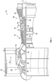
FIG. 1 is a partial cross-sectional view of a gas turbine engine; -
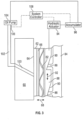
FIG. 2 is a cross-sectional view of an embodiment of a contacting seal for a gas turbine engine; and -
FIG. 3 is another cross-sectional view of an embodiment of a contacting seal for a gas turbine engine along section A-A ofFIG. 2 ; -
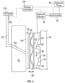
FIG. 4 is yet another cross-sectional view of an embodiment of a contacting seal for a gas turbine engine along section A-A ofFIG. 2 . - A detailed description of one or more embodiments of the disclosed apparatus and method are presented herein by way of exemplification and not limitation with reference to the Figures.
-
FIG. 1 schematically illustrates agas turbine engine 20. Thegas turbine engine 20 is disclosed herein as a two-spool turbofan that generally incorporates afan section 22, acompressor section 24, acombustor section 26 and aturbine section 28. Alternative engines might include other systems or features. Thefan section 22 drives air along a bypass flow path B in a bypass duct, while thecompressor section 24 drives air along a core flow path C for compression and communication into thecombustor section 26 then expansion through theturbine section 28. Although depicted as a two-spool turbofan gas turbine engine in the disclosed non-limiting embodiment, it should be understood that the concepts described herein are not limited to use with two-spool turbofans as the teachings may be applied to other types of turbine engines including three-spool architectures. - The
exemplary engine 20 generally includes alow speed spool 30 and ahigh speed spool 32 mounted for rotation about an engine central longitudinal axis A relative to an enginestatic structure 36 viaseveral bearing systems 38. It should be understood thatvarious bearing systems 38 at various locations may alternatively or additionally be provided, and the location ofbearing systems 38 may be varied as appropriate to the application. - The
low speed spool 30 generally includes aninner shaft 40 that interconnects afan 42, alow pressure compressor 44 and alow pressure turbine 46. Theinner shaft 40 is connected to thefan 42 through a speed change mechanism, which in exemplarygas turbine engine 20 is illustrated as a gearedarchitecture 48 to drive thefan 42 at a lower speed than thelow speed spool 30. Thehigh speed spool 32 includes anouter shaft 50 that interconnects ahigh pressure compressor 52 and high pressure turbine 54. Acombustor 56 is arranged inexemplary gas turbine 20 between thehigh pressure compressor 52 and the high pressure turbine 54. An enginestatic structure 36 is arranged generally between the high pressure turbine 54 and thelow pressure turbine 46. The enginestatic structure 36 further supports bearingsystems 38 in theturbine section 28. Theinner shaft 40 and theouter shaft 50 are concentric and rotate viabearing systems 38 about the engine central longitudinal axis A which is collinear with their longitudinal axes. - The core airflow is compressed by the
low pressure compressor 44 then thehigh pressure compressor 52, mixed and burned with fuel in thecombustor 56, then expanded over the high pressure turbine 54 andlow pressure turbine 46. Theturbines 46, 54 rotationally drive the respectivelow speed spool 30 andhigh speed spool 32 in response to the expansion. It will be appreciated that each of the positions of thefan section 22,compressor section 24,combustor section 26,turbine section 28, and fandrive gear system 48 may be varied. For example,gear system 48 may be located aft ofcombustor section 26 or even aft ofturbine section 28, andfan section 22 may be positioned forward or aft of the location ofgear system 48. - The
engine 20 in one example is a high-bypass geared aircraft engine. In a further example, theengine 20 bypass ratio is greater than about six (6), with an example embodiment being greater than about ten (10), the gearedarchitecture 48 is an epicyclic gear train, such as a planetary gear system or other gear system, with a gear reduction ratio of greater than about 2.3 and thelow pressure turbine 46 has a pressure ratio that is greater than about five. In one disclosed embodiment, theengine 20 bypass ratio is greater than about ten (10:1), the fan diameter is significantly larger than that of thelow pressure compressor 44, and thelow pressure turbine 46 has a pressure ratio that is greater than about five (5:1).Low pressure turbine 46 pressure ratio is pressure measured prior to inlet oflow pressure turbine 46 as related to the pressure at the outlet of thelow pressure turbine 46 prior to an exhaust nozzle. The gearedarchitecture 48 may be an epicyclic gear train, such as a planetary gear system or other gear system, with a gear reduction ratio of greater than about 2.3:1. It should be understood, however, that the above parameters are only exemplary of one embodiment of a geared architecture engine and that the present disclosure is applicable to other gas turbine engines including direct drive turbofans. - A significant amount of thrust is provided by the bypass flow B due to the high bypass ratio. The
fan section 22 of theengine 20 is designed for a particular flight condition--typically cruise at about 0.8 Mach and about 35,000 feet (10,668 meters). The flight condition of 0.8 Mach and 35,000 ft (10,668 meters), with the engine at its best fuel consumption--also known as "bucket cruise Thrust Specific Fuel Consumption ('TSFC')"--is the industry standard parameter of lbm of fuel being burned divided by lbf of thrust the engine produces at that minimum point. "Low fan pressure ratio" is the pressure ratio across the fan blade alone, without a Fan Exit Guide Vane ("FEGV") system. The low fan pressure ratio as disclosed herein according to one non-limiting embodiment is less than about 1.45. "Low corrected fan tip speed" is the actual fan tip speed in ft/sec divided by an industry standard temperature correction of [(Tram °R)/(518.7 °R)]0.5. The "Low corrected fan tip speed" as disclosed herein according to one non-limiting embodiment is less than about 1150 ft/second (350.5 m/sec). - Referring now to
FIG. 2 , the bearing systems 38 (shown inFIG. 1 ) are sealed to maintain a supply of lubrication and cooling oil within the bearingsystems 38, also referred to herein as a bearing compartment. The seal arrangement at thebearing system 38 includes aseal seat 60 and aseal element 62 in contact with theseal seat 60 at aninterface surface 64. Theseal seat 60 is operably connected to and rotates with a rotating component of thegas turbine engine 20, for example, theinner shaft 40 or theouter shaft 50. Theseal element 62 is formed from, for example, carbon. The seal arrangement generates a high degree of friction, and to reduce friction and dissipate heat generated at the interface surface 64 a flow of lubricant, for example, oil, is directed through theseal seat 60 to theinterface surface 64 via a plurality of oil flow channels (not shown). The seal arrangement described herein is a wet-face seal, with lubricant provided to theinterface surface 64. One skilled in the art will readily appreciate, however, that the present disclosure may be readily applied to dry-face seal arrangements in which lubricant is provided through channels in theseal seat 60, but not directed to theinterface surface 64. - The
seal element 62 is retained in aseal carrier 66, which is movable along anaxial direction 68 parallel to the engine central longitudinal axis A. Theseal carrier 66 is circumferentially retained by one or more anti-rotation guides 76 secured to thestatic structure 74. Theanti-rotation guide 76 extends axially though ananti-rotation opening 78 in theseal carrier 66. Theanti-rotation guide 76 may further include ananti-rotation stop 80 at an axial end of theanti-rotation guide 76. In some embodiments, asecondary seal 70 extends between thestatic structure 74 and theseal element 62, with theseal element 62 translatable along theaxial direction 68 relative to thesecondary seal 70. In some embodiments, thesecondary seal 70 is retained in aseal groove 72 in thestatic structure 74. - The position of the
seal element 62 relative to theseal seat 60 is actively controlled such that a contact force between theseal element 62 and theseal seat 60 at theinterface surface 64 may be selectably varied. For example, when there is sufficient lubricant flow to theinterface surface 64 theseal element 62 may be moved so that the contact force is relatively high, but when the flow of lubricant to theinterface surface 64 is below a threshold theseal element 62 is moved axially away from theseal seat 60 to reduce the contact force thus reducing damage to theseal element 62 until sufficient oil flow to theinterface surface 64 is restored. To actively control the position of theseal element 62 relative to theseal seat 60, the seal arrangement includes awave spring 82, aramp 84 and aramp follower 88, as will be described in further detail below with reference toFIG. 3 . - Referring now to
FIG. 3 , illustrated is a schematic view of an actively-controlled actuation system for aseal element 62. Thewave spring 82 abuts theseal carrier 66 and applies an axial force on theseal carrier 66 to urge theseal element 62 into contact with theseal seat 60. The axial force applied by thewave spring 82 varies through the use of aramp 84 andramp follower 88 arrangement located at thewave spring 82 opposite theseal carrier 66. The rotationallystationary ramp 84 includes a plurality of circumferentially-spacedramp teeth 86. In some embodiments, theramp 84 is a full circumferential ring. In other embodiments, the ramp may comprise a plurality of circumferential ramp segments. Theramp follower 88 is disposed axially between theramp 84 and thewave spring 82. Theramp follower 88 includes a plurality ofcomplimentary follower teeth 90. Eachfollower tooth 90 of the plurality offollower teeth 90 meshes with aramp tooth 86 of the plurality oframp teeth 86. Theramp follower 88 is movable in thecircumferential direction 92. - Moving the
ramp follower 88 in the firstcircumferential direction 92, downward on the page as shown inFIG. 3 , causes the plurality offollower teeth 90 to ride up theirrespective ramp teeth 86, thereby resulting in axial movement of theramp follower 88 toward theseal seat 60. This movement urges thewave spring 82 to exert increased axial force on theseal carrier 66, thus increasing the contact force between theseal seat 60 and theseal element 62 at theinterface surface 64. Conversely, moving theramp follower 88 in the secondcircumferential direction 92, upward on the page as shown inFIG. 3 , causes the plurality offollower teeth 90 to ride down theirrespective ramp teeth 86, thereby resulting in axial movement of theramp follower 88 away from theseal seat 60. This movement relaxes thewave spring 82, thus reducing the contact force between theseal seat 60 and theseal element 62 at theinterface surface 64. - The position of the
ramp follower 88 is actively controlled via, for example, ahydraulic actuator 94. Thehydraulic actuator 94 is operably connected to theramp follower 88 to urge circumferential motion of theramp follower 88. Thehydraulic actuator 94 utilizes a flow of hydraulic fluid from, for example, anaccumulator 96, urged to and/or from thehydraulic actuator 94 by theengine oil pump 104 as shown inFIG. 3 . While ahydraulic actuator 94 is described herein to drive motion of theramp follower 88, it is to be appreciated that in other embodiments other types of actuators such as, for example, electromechanical actuators may be used. - In another embodiment, as illustrated in
FIG. 4 , thehydraulic actuator 94 is operably connected to theramp follower 88 to urge circumferential motion of theramp follower 88. Thehydraulic actuator 94 utilizes a flow of hydraulic fluid from, for example, anaccumulator 96, urged to and/or from thehydraulic actuator 94 by a separatehydraulic pump 98. - A flow of oil is urged through one or more
oil flow channels 100 in theseal seat 60 to theinterface surface 64. Theoil flow channels 100 are supplied with the flow of oil through one ormore oil lines 102 connected to anoil pump 104. In some embodiments one ormore oil sensors 106 are disposed at theoil pump 104 or along the one ormore oil lines 102 to detect the flow of oil therethrough. Theoil sensors 106 may be, for example, oil pressure sensors. Theoil sensors 106 and thehydraulic actuator 94 and/or thehydraulic pump 98 are connected to asystem controller 108. When theoil sensor 106 detects a flow of oil below a preselected threshold, for example, an oil pressure below a pressure threshold, thesystem controller 108 commands thehydraulic actuator 94 to move theramp follower 88 in the secondcircumferential direction 92, upward on the page as shown inFIG. 3 , causing the plurality offollower teeth 90 to ride down theirrespective ramp teeth 86, thereby resulting in axial movement of theramp follower 88 away from theseal seat 60. This movement relaxes thewave spring 82, thus reducing the contact force between theseal seat 60 and theseal element 62 at theinterface surface 64. This reduces the potential for damage to theseal element 62 and/or theseal seat 60 due to high friction conditions due to the reduced oil flow. - When the
oil sensor 106 detects that the oil pressure has returned to above the threshold thesystem control 108 commands thehydraulic actuator 94 to moveramp follower 88 in the firstcircumferential direction 92, downward on the page as shown inFIG. 3 , causing the plurality offollower teeth 90 to ride up theirrespective ramp teeth 86, thereby resulting in axial movement of theramp follower 88 toward theseal seat 60. This movement urges thewave spring 82 to exert increased axial force on theseal carrier 66, thus increasing the contact force between theseal seat 60 and theseal element 62 at theinterface surface 64. - The
seal element 62 position control system and method disclosed herein reduces friction and heat generation at theinterface surface 64 thereby reducing damage due to oil flow interruption. This reduces damage to the seals during such events and thereby extends the service life of theseal elements 62 and or the seal seats 60. - The term "about" is intended to include the degree of error associated with measurement of the particular quantity based upon the equipment available at the time of filing the application. For example, "about" can include a range of ± 8% or 5%, or 2% of a given value.
- The terminology used herein is for the purpose of describing particular embodiments only and is not intended to be limiting of the present disclosure. As used herein, the singular forms "a", "an" and "the" are intended to include the plural forms as well, unless the context clearly indicates otherwise. It will be further understood that the terms "comprises" and/or "comprising," when used in this specification, specify the presence of stated features, integers, steps, operations, elements, and/or components, but do not preclude the presence or addition of one or more other features, integers, steps, operations, element components, and/or groups thereof.
- While the present disclosure has been described with reference to an exemplary embodiment or embodiments, it will be understood by those skilled in the art that various changes may be made and equivalents may be substituted for elements thereof without departing from the scope of the present disclosure. In addition, many modifications may be made to adapt a particular situation or material to the teachings of the present disclosure without departing from the essential scope thereof. Therefore, it is intended that the present disclosure not be limited to the particular embodiment disclosed as the best mode contemplated for carrying out this present disclosure, but that the present disclosure will include all embodiments falling within the scope of the claims.
Claims (12)
- A contacting seal for a gas turbine engine (20), comprising:a seal seat (60) configured to rotate circumferentially about an axis of rotation (A);a seal element (62) configured to contact the seal seat at an interface surface (64), the seal element rotationally fixed relative to the axis of rotation; andan actively-controlled actuation system operably connected to the seal element to control a contact force between the seal element and the seal seat at the interface surface based on a level of lubricant flow to the interface surface,characterized in that the actuation system includes:(86); a rotationally-stationary ramp (84) including a plurality of ramp teetha rotationally-movable ramp follower (88) including a plurality of complimentary follower teeth (90) meshed with the plurality of ramp teeth;wherein circumferential movement of the ramp follower in a first direction relative to the ramp urges the seal element (62) toward the seal seat (60) thereby increasing the contact force; andwherein circumferential movement of the ramp follower in a second direction opposite the first direction reduces the contact force.
- The contacting seal of claim 1, further comprising a wave spring (82) disposed between the ramp follower (88) and the seal element (62).
- The contacting seal of claim 1 or 2, further comprising an actuator (94) operably connected to the ramp follower (88) and configured to urge circumferential movement of the ramp follower relative to the ramp (84).
- The contacting seal of claim 3, wherein the actuator (94) is a hydraulic actuator.
- The contacting seal of any preceding claim, further comprising one or more oil sensors (106) operably connected to the actuation system, wherein the contact force is reduced when the level of lubricant flow is below a threshold.
- The contacting seal of any preceding claim, wherein the seal element (62) is a carbon seal element.
- A gas turbine engine (20), comprising:a rotating shaft (40; 50);one or more bearing arrangements (38) supportive of the rotating shaft; anda contacting seal of any preceding claim configured to seal a bearing arrangement of the one or more bearing arrangements.
- A method of operating a contacting seal of a gas turbine engine (20), comprising:positioning a rotationally fixed seal element (62) in contact with a rotating seal seat (60) at an interface surface (64) between the seal seat and the seal element;actively-controlling a contact pressure between the seal seat and the seal element at the interface surface utilizing an actuation system, the contact pressure based on a level of lubricant flow to the interface surface;meshing a plurality of ramp teeth (86) of a rotationally stationary ramp (84) with a plurality of follower teeth (90) of a rotationally movable ramp follower (88); andmoving the ramp follower in a circumferential direction relative to the ramp to adjust the contact pressure at the interface surface;wherein circumferential movement of the ramp follower in a first direction relative to the ramp urges the seal element (62) toward the seal seat (60) thereby increasing the contact force; andwherein circumferential movement of the ramp follower in a second direction opposite the first direction reduces the contact force.
- The method of claim 8, further comprising biasing the seal element (62) toward the seal seat (60) via a wave spring (82) disposed between the seal element and the ramp follower (88).
- The method of claim 8 or 9, further comprising detecting the level of lubricant flow to the interface surface (64) via one or more oil sensors (106).
- The method of claim 10, further comprising reducing the contact force when the detected level of lubricant flow is below a preselected threshold.
- The method of claim 10 or 11, further comprising increasing the contact force when the detected level of lubricant flow is above the preselected threshold.
Applications Claiming Priority (1)
| Application Number | Priority Date | Filing Date | Title |
|---|---|---|---|
| US16/295,105 US10927760B2 (en) | 2019-03-07 | 2019-03-07 | Actively controlled contacting seal |
Publications (2)
| Publication Number | Publication Date |
|---|---|
| EP3705759A1 EP3705759A1 (en) | 2020-09-09 |
| EP3705759B1 true EP3705759B1 (en) | 2023-04-05 |
Family
ID=69024181
Family Applications (1)
| Application Number | Title | Priority Date | Filing Date |
|---|---|---|---|
| EP19219626.9A Active EP3705759B1 (en) | 2019-03-07 | 2019-12-24 | Actively controlled contacting seal |
Country Status (2)
| Country | Link |
|---|---|
| US (1) | US10927760B2 (en) |
| EP (1) | EP3705759B1 (en) |
Families Citing this family (3)
| Publication number | Priority date | Publication date | Assignee | Title |
|---|---|---|---|---|
| US11454324B2 (en) * | 2020-08-26 | 2022-09-27 | Raytheon Technologies Corporation | Face seal carrier arrester |
| CN112797078A (en) * | 2021-02-05 | 2021-05-14 | 中国航发沈阳发动机研究所 | Bearing seal supporting structure |
| US12392412B2 (en) | 2022-12-15 | 2025-08-19 | Rtx Corporation | Hydraulically supported face seal |
Family Cites Families (12)
| Publication number | Priority date | Publication date | Assignee | Title |
|---|---|---|---|---|
| DE1247096B (en) | 1962-03-23 | 1967-08-10 | Continental Jllinois Nat Bank | Mechanical seal |
| GB1170382A (en) | 1967-06-23 | 1969-11-12 | Rolls Royce | Bearing Assembly |
| SE392642B (en) | 1974-03-11 | 1977-04-04 | Reinhall Rolf Bertil | DEVIBRATOR OR RAFFINOR DEVICE |
| USRE30994E (en) | 1978-03-02 | 1982-07-13 | Dunham-Bush, Inc. | Vertical axis hermetic rotary helical screw compressor with improved rotary bearings and oil management |
| US4181474A (en) | 1978-03-02 | 1980-01-01 | Dunham-Bush, Inc. | Vertical axis hermetic rotary helical screw compressor with improved rotary bearings and oil management |
| FR2577000B1 (en) | 1985-02-01 | 1987-03-27 | Neyrpic | BALANCED ROTATING JOINT FOR SEALING A HYDRAULIC TURBINE SHAFT |
| US4928978A (en) * | 1988-04-07 | 1990-05-29 | United Technologies Corporation | Rotating shaft seal |
| KR100878460B1 (en) * | 2007-07-06 | 2009-01-13 | 한국과학기술연구원 | Labyrinth seal |
| DE102013009759A1 (en) | 2013-06-11 | 2014-12-11 | Christian Maier Gmbh & Co. Kg Maschinenfabrik | Device for transporting media |
| CN105987044A (en) | 2015-03-05 | 2016-10-05 | 无锡大金高精度冷拔钢管有限公司 | Oil-leakage-preventing oil cylinder with wave spring for marine equipment engineering |
| US10415707B2 (en) * | 2016-06-30 | 2019-09-17 | General Electric Company | Face seal assembly and an associated method thereof |
| WO2018213313A1 (en) | 2017-05-15 | 2018-11-22 | John Crane Uk Ltd. | Dry gas seal with electronically controlled carrier load |
-
2019
- 2019-03-07 US US16/295,105 patent/US10927760B2/en active Active
- 2019-12-24 EP EP19219626.9A patent/EP3705759B1/en active Active
Also Published As
| Publication number | Publication date |
|---|---|
| US20200284196A1 (en) | 2020-09-10 |
| US10927760B2 (en) | 2021-02-23 |
| EP3705759A1 (en) | 2020-09-09 |
Similar Documents
| Publication | Publication Date | Title |
|---|---|---|
| EP3677818B1 (en) | Cantilevered hydrostatic advanced low leakage seal | |
| EP4053383B1 (en) | Piston ring shuttle carrier | |
| EP3680520B1 (en) | Hydrostatic seal with enhanced maneuver response | |
| EP3039251A1 (en) | Gas turbine engine with fan clearance control | |
| EP3705759A1 (en) | Actively controlled contacting seal | |
| EP3789589B1 (en) | Hydrostatic seal | |
| EP3620608B1 (en) | Bearing assembly with a reduced axial space self-pressurizing damper and corresponding method for maintaining pressure in said damper | |
| EP3498984B1 (en) | Seal retention assembly for gas turbine engine and corresponding method of assembly | |
| EP3543566B1 (en) | Ramped spacer ring seal | |
| EP3789588B1 (en) | Hydrostatic seal aligned with rotor rotation | |
| EP3693555A1 (en) | Face seal with damper | |
| US20200025097A1 (en) | Hydrostatic seal with abradable teeth for gas turbine engine | |
| EP3102810A1 (en) | Circumferential axial segmented trough seal | |
| EP3960993B1 (en) | Face seal carrier arrester | |
| EP3960992A2 (en) | Seal runner flow damper | |
| US11549384B2 (en) | Face seal arrangement | |
| EP3052769B1 (en) | Translating compressor and turbine rotors for clearance control | |
| EP4386179A1 (en) | Gas turbine engine with split helical piston seal | |
| EP3650660B1 (en) | Gas turbine engine casing with embedded actuation features | |
| EP4455453A2 (en) | Failsafe blade outer airseal retention | |
| EP4375484A1 (en) | Gas turbine engine with carbon/carbon composite piston seal | |
| EP4455454A2 (en) | Shared load path blade outer air seal | |
| EP4461930A1 (en) | Radially retractable outer air seal | |
| EP3859125B1 (en) | Gas turbine engine having a sealing member |
Legal Events
| Date | Code | Title | Description |
|---|---|---|---|
| PUAI | Public reference made under article 153(3) epc to a published international application that has entered the european phase |
Free format text: ORIGINAL CODE: 0009012 |
|
| STAA | Information on the status of an ep patent application or granted ep patent |
Free format text: STATUS: THE APPLICATION HAS BEEN PUBLISHED |
|
| AK | Designated contracting states |
Kind code of ref document: A1 Designated state(s): AL AT BE BG CH CY CZ DE DK EE ES FI FR GB GR HR HU IE IS IT LI LT LU LV MC MK MT NL NO PL PT RO RS SE SI SK SM TR |
|
| AX | Request for extension of the european patent |
Extension state: BA ME |
|
| STAA | Information on the status of an ep patent application or granted ep patent |
Free format text: STATUS: REQUEST FOR EXAMINATION WAS MADE |
|
| RAP1 | Party data changed (applicant data changed or rights of an application transferred) |
Owner name: RAYTHEON TECHNOLOGIES CORPORATION |
|
| 17P | Request for examination filed |
Effective date: 20210309 |
|
| RBV | Designated contracting states (corrected) |
Designated state(s): AL AT BE BG CH CY CZ DE DK EE ES FI FR GB GR HR HU IE IS IT LI LT LU LV MC MK MT NL NO PL PT RO RS SE SI SK SM TR |
|
| GRAP | Despatch of communication of intention to grant a patent |
Free format text: ORIGINAL CODE: EPIDOSNIGR1 |
|
| STAA | Information on the status of an ep patent application or granted ep patent |
Free format text: STATUS: GRANT OF PATENT IS INTENDED |
|
| INTG | Intention to grant announced |
Effective date: 20221011 |
|
| GRAS | Grant fee paid |
Free format text: ORIGINAL CODE: EPIDOSNIGR3 |
|
| GRAA | (expected) grant |
Free format text: ORIGINAL CODE: 0009210 |
|
| STAA | Information on the status of an ep patent application or granted ep patent |
Free format text: STATUS: THE PATENT HAS BEEN GRANTED |
|
| AK | Designated contracting states |
Kind code of ref document: B1 Designated state(s): AL AT BE BG CH CY CZ DE DK EE ES FI FR GB GR HR HU IE IS IT LI LT LU LV MC MK MT NL NO PL PT RO RS SE SI SK SM TR |
|
| REG | Reference to a national code |
Ref country code: GB Ref legal event code: FG4D |
|
| REG | Reference to a national code |
Ref country code: DE Ref legal event code: R096 Ref document number: 602019027151 Country of ref document: DE |
|
| REG | Reference to a national code |
Ref country code: CH Ref legal event code: EP |
|
| REG | Reference to a national code |
Ref country code: AT Ref legal event code: REF Ref document number: 1558458 Country of ref document: AT Kind code of ref document: T Effective date: 20230415 |
|
| REG | Reference to a national code |
Ref country code: IE Ref legal event code: FG4D |
|
| P01 | Opt-out of the competence of the unified patent court (upc) registered |
Effective date: 20230521 |
|
| REG | Reference to a national code |
Ref country code: LT Ref legal event code: MG9D |
|
| REG | Reference to a national code |
Ref country code: NL Ref legal event code: MP Effective date: 20230405 |
|
| REG | Reference to a national code |
Ref country code: AT Ref legal event code: MK05 Ref document number: 1558458 Country of ref document: AT Kind code of ref document: T Effective date: 20230405 |
|
| PG25 | Lapsed in a contracting state [announced via postgrant information from national office to epo] |
Ref country code: NL Free format text: LAPSE BECAUSE OF FAILURE TO SUBMIT A TRANSLATION OF THE DESCRIPTION OR TO PAY THE FEE WITHIN THE PRESCRIBED TIME-LIMIT Effective date: 20230405 |
|
| PG25 | Lapsed in a contracting state [announced via postgrant information from national office to epo] |
Ref country code: SE Free format text: LAPSE BECAUSE OF FAILURE TO SUBMIT A TRANSLATION OF THE DESCRIPTION OR TO PAY THE FEE WITHIN THE PRESCRIBED TIME-LIMIT Effective date: 20230405 Ref country code: PT Free format text: LAPSE BECAUSE OF FAILURE TO SUBMIT A TRANSLATION OF THE DESCRIPTION OR TO PAY THE FEE WITHIN THE PRESCRIBED TIME-LIMIT Effective date: 20230807 Ref country code: NO Free format text: LAPSE BECAUSE OF FAILURE TO SUBMIT A TRANSLATION OF THE DESCRIPTION OR TO PAY THE FEE WITHIN THE PRESCRIBED TIME-LIMIT Effective date: 20230705 Ref country code: ES Free format text: LAPSE BECAUSE OF FAILURE TO SUBMIT A TRANSLATION OF THE DESCRIPTION OR TO PAY THE FEE WITHIN THE PRESCRIBED TIME-LIMIT Effective date: 20230405 Ref country code: AT Free format text: LAPSE BECAUSE OF FAILURE TO SUBMIT A TRANSLATION OF THE DESCRIPTION OR TO PAY THE FEE WITHIN THE PRESCRIBED TIME-LIMIT Effective date: 20230405 |
|
| RAP4 | Party data changed (patent owner data changed or rights of a patent transferred) |
Owner name: RTX CORPORATION |
|
| PG25 | Lapsed in a contracting state [announced via postgrant information from national office to epo] |
Ref country code: RS Free format text: LAPSE BECAUSE OF FAILURE TO SUBMIT A TRANSLATION OF THE DESCRIPTION OR TO PAY THE FEE WITHIN THE PRESCRIBED TIME-LIMIT Effective date: 20230405 Ref country code: PL Free format text: LAPSE BECAUSE OF FAILURE TO SUBMIT A TRANSLATION OF THE DESCRIPTION OR TO PAY THE FEE WITHIN THE PRESCRIBED TIME-LIMIT Effective date: 20230405 Ref country code: LV Free format text: LAPSE BECAUSE OF FAILURE TO SUBMIT A TRANSLATION OF THE DESCRIPTION OR TO PAY THE FEE WITHIN THE PRESCRIBED TIME-LIMIT Effective date: 20230405 Ref country code: LT Free format text: LAPSE BECAUSE OF FAILURE TO SUBMIT A TRANSLATION OF THE DESCRIPTION OR TO PAY THE FEE WITHIN THE PRESCRIBED TIME-LIMIT Effective date: 20230405 Ref country code: IS Free format text: LAPSE BECAUSE OF FAILURE TO SUBMIT A TRANSLATION OF THE DESCRIPTION OR TO PAY THE FEE WITHIN THE PRESCRIBED TIME-LIMIT Effective date: 20230805 Ref country code: HR Free format text: LAPSE BECAUSE OF FAILURE TO SUBMIT A TRANSLATION OF THE DESCRIPTION OR TO PAY THE FEE WITHIN THE PRESCRIBED TIME-LIMIT Effective date: 20230405 Ref country code: GR Free format text: LAPSE BECAUSE OF FAILURE TO SUBMIT A TRANSLATION OF THE DESCRIPTION OR TO PAY THE FEE WITHIN THE PRESCRIBED TIME-LIMIT Effective date: 20230706 Ref country code: AL Free format text: LAPSE BECAUSE OF FAILURE TO SUBMIT A TRANSLATION OF THE DESCRIPTION OR TO PAY THE FEE WITHIN THE PRESCRIBED TIME-LIMIT Effective date: 20230405 |
|
| PG25 | Lapsed in a contracting state [announced via postgrant information from national office to epo] |
Ref country code: FI Free format text: LAPSE BECAUSE OF FAILURE TO SUBMIT A TRANSLATION OF THE DESCRIPTION OR TO PAY THE FEE WITHIN THE PRESCRIBED TIME-LIMIT Effective date: 20230405 |
|
| REG | Reference to a national code |
Ref country code: DE Ref legal event code: R097 Ref document number: 602019027151 Country of ref document: DE |
|
| PG25 | Lapsed in a contracting state [announced via postgrant information from national office to epo] |
Ref country code: SK Free format text: LAPSE BECAUSE OF FAILURE TO SUBMIT A TRANSLATION OF THE DESCRIPTION OR TO PAY THE FEE WITHIN THE PRESCRIBED TIME-LIMIT Effective date: 20230405 |
|
| PG25 | Lapsed in a contracting state [announced via postgrant information from national office to epo] |
Ref country code: SM Free format text: LAPSE BECAUSE OF FAILURE TO SUBMIT A TRANSLATION OF THE DESCRIPTION OR TO PAY THE FEE WITHIN THE PRESCRIBED TIME-LIMIT Effective date: 20230405 Ref country code: SK Free format text: LAPSE BECAUSE OF FAILURE TO SUBMIT A TRANSLATION OF THE DESCRIPTION OR TO PAY THE FEE WITHIN THE PRESCRIBED TIME-LIMIT Effective date: 20230405 Ref country code: RO Free format text: LAPSE BECAUSE OF FAILURE TO SUBMIT A TRANSLATION OF THE DESCRIPTION OR TO PAY THE FEE WITHIN THE PRESCRIBED TIME-LIMIT Effective date: 20230405 Ref country code: EE Free format text: LAPSE BECAUSE OF FAILURE TO SUBMIT A TRANSLATION OF THE DESCRIPTION OR TO PAY THE FEE WITHIN THE PRESCRIBED TIME-LIMIT Effective date: 20230405 Ref country code: DK Free format text: LAPSE BECAUSE OF FAILURE TO SUBMIT A TRANSLATION OF THE DESCRIPTION OR TO PAY THE FEE WITHIN THE PRESCRIBED TIME-LIMIT Effective date: 20230405 Ref country code: CZ Free format text: LAPSE BECAUSE OF FAILURE TO SUBMIT A TRANSLATION OF THE DESCRIPTION OR TO PAY THE FEE WITHIN THE PRESCRIBED TIME-LIMIT Effective date: 20230405 |
|
| PLBE | No opposition filed within time limit |
Free format text: ORIGINAL CODE: 0009261 |
|
| STAA | Information on the status of an ep patent application or granted ep patent |
Free format text: STATUS: NO OPPOSITION FILED WITHIN TIME LIMIT |
|
| 26N | No opposition filed |
Effective date: 20240108 |
|
| PG25 | Lapsed in a contracting state [announced via postgrant information from national office to epo] |
Ref country code: SI Free format text: LAPSE BECAUSE OF FAILURE TO SUBMIT A TRANSLATION OF THE DESCRIPTION OR TO PAY THE FEE WITHIN THE PRESCRIBED TIME-LIMIT Effective date: 20230405 |
|
| PG25 | Lapsed in a contracting state [announced via postgrant information from national office to epo] |
Ref country code: SI Free format text: LAPSE BECAUSE OF FAILURE TO SUBMIT A TRANSLATION OF THE DESCRIPTION OR TO PAY THE FEE WITHIN THE PRESCRIBED TIME-LIMIT Effective date: 20230405 Ref country code: IT Free format text: LAPSE BECAUSE OF FAILURE TO SUBMIT A TRANSLATION OF THE DESCRIPTION OR TO PAY THE FEE WITHIN THE PRESCRIBED TIME-LIMIT Effective date: 20230405 |
|
| REG | Reference to a national code |
Ref country code: CH Ref legal event code: PL |
|
| PG25 | Lapsed in a contracting state [announced via postgrant information from national office to epo] |
Ref country code: LU Free format text: LAPSE BECAUSE OF NON-PAYMENT OF DUE FEES Effective date: 20231224 |
|
| PG25 | Lapsed in a contracting state [announced via postgrant information from national office to epo] |
Ref country code: MC Free format text: LAPSE BECAUSE OF FAILURE TO SUBMIT A TRANSLATION OF THE DESCRIPTION OR TO PAY THE FEE WITHIN THE PRESCRIBED TIME-LIMIT Effective date: 20230405 |
|
| REG | Reference to a national code |
Ref country code: BE Ref legal event code: MM Effective date: 20231231 |
|
| PG25 | Lapsed in a contracting state [announced via postgrant information from national office to epo] |
Ref country code: MC Free format text: LAPSE BECAUSE OF FAILURE TO SUBMIT A TRANSLATION OF THE DESCRIPTION OR TO PAY THE FEE WITHIN THE PRESCRIBED TIME-LIMIT Effective date: 20230405 Ref country code: LU Free format text: LAPSE BECAUSE OF NON-PAYMENT OF DUE FEES Effective date: 20231224 |
|
| REG | Reference to a national code |
Ref country code: IE Ref legal event code: MM4A |
|
| PG25 | Lapsed in a contracting state [announced via postgrant information from national office to epo] |
Ref country code: IE Free format text: LAPSE BECAUSE OF NON-PAYMENT OF DUE FEES Effective date: 20231224 |
|
| PG25 | Lapsed in a contracting state [announced via postgrant information from national office to epo] |
Ref country code: BE Free format text: LAPSE BECAUSE OF NON-PAYMENT OF DUE FEES Effective date: 20231231 |
|
| PG25 | Lapsed in a contracting state [announced via postgrant information from national office to epo] |
Ref country code: CH Free format text: LAPSE BECAUSE OF NON-PAYMENT OF DUE FEES Effective date: 20231231 |
|
| PG25 | Lapsed in a contracting state [announced via postgrant information from national office to epo] |
Ref country code: IE Free format text: LAPSE BECAUSE OF NON-PAYMENT OF DUE FEES Effective date: 20231224 Ref country code: CH Free format text: LAPSE BECAUSE OF NON-PAYMENT OF DUE FEES Effective date: 20231231 Ref country code: BE Free format text: LAPSE BECAUSE OF NON-PAYMENT OF DUE FEES Effective date: 20231231 |
|
| PG25 | Lapsed in a contracting state [announced via postgrant information from national office to epo] |
Ref country code: BG Free format text: LAPSE BECAUSE OF FAILURE TO SUBMIT A TRANSLATION OF THE DESCRIPTION OR TO PAY THE FEE WITHIN THE PRESCRIBED TIME-LIMIT Effective date: 20230405 |
|
| PG25 | Lapsed in a contracting state [announced via postgrant information from national office to epo] |
Ref country code: BG Free format text: LAPSE BECAUSE OF FAILURE TO SUBMIT A TRANSLATION OF THE DESCRIPTION OR TO PAY THE FEE WITHIN THE PRESCRIBED TIME-LIMIT Effective date: 20230405 |
|
| PG25 | Lapsed in a contracting state [announced via postgrant information from national office to epo] |
Ref country code: CY Free format text: LAPSE BECAUSE OF FAILURE TO SUBMIT A TRANSLATION OF THE DESCRIPTION OR TO PAY THE FEE WITHIN THE PRESCRIBED TIME-LIMIT; INVALID AB INITIO Effective date: 20191224 |
|
| PG25 | Lapsed in a contracting state [announced via postgrant information from national office to epo] |
Ref country code: HU Free format text: LAPSE BECAUSE OF FAILURE TO SUBMIT A TRANSLATION OF THE DESCRIPTION OR TO PAY THE FEE WITHIN THE PRESCRIBED TIME-LIMIT; INVALID AB INITIO Effective date: 20191224 |
|
| REG | Reference to a national code |
Ref country code: DE Ref legal event code: R081 Ref document number: 602019027151 Country of ref document: DE Owner name: RTX CORPORATION (N.D.GES.D. STAATES DELAWARE),, US Free format text: FORMER OWNER: RAYTHEON TECHNOLOGIES CORPORATION, FARMINGTON, CT, US |
|
| PG25 | Lapsed in a contracting state [announced via postgrant information from national office to epo] |
Ref country code: TR Free format text: LAPSE BECAUSE OF FAILURE TO SUBMIT A TRANSLATION OF THE DESCRIPTION OR TO PAY THE FEE WITHIN THE PRESCRIBED TIME-LIMIT Effective date: 20230405 |
|
| PGFP | Annual fee paid to national office [announced via postgrant information from national office to epo] |
Ref country code: DE Payment date: 20251126 Year of fee payment: 7 |
|
| PGFP | Annual fee paid to national office [announced via postgrant information from national office to epo] |
Ref country code: GB Payment date: 20251119 Year of fee payment: 7 |
|
| PGFP | Annual fee paid to national office [announced via postgrant information from national office to epo] |
Ref country code: FR Payment date: 20251120 Year of fee payment: 7 |