EP3705734A1 - Pneumatic actuator - Google Patents
Pneumatic actuator Download PDFInfo
- Publication number
- EP3705734A1 EP3705734A1 EP17930230.2A EP17930230A EP3705734A1 EP 3705734 A1 EP3705734 A1 EP 3705734A1 EP 17930230 A EP17930230 A EP 17930230A EP 3705734 A1 EP3705734 A1 EP 3705734A1
- Authority
- EP
- European Patent Office
- Prior art keywords
- cords
- sleeve
- constituting
- actuator
- pneumatic actuator
- Prior art date
- Legal status (The legal status is an assumption and is not a legal conclusion. Google has not performed a legal analysis and makes no representation as to the accuracy of the status listed.)
- Pending
Links
- 238000009941 weaving Methods 0.000 claims abstract description 14
- 239000000835 fiber Substances 0.000 claims description 22
- 230000008602 contraction Effects 0.000 claims description 20
- 230000002093 peripheral effect Effects 0.000 claims description 13
- 239000004952 Polyamide Substances 0.000 claims description 4
- 229920002647 polyamide Polymers 0.000 claims description 4
- 229920002972 Acrylic fiber Polymers 0.000 claims description 3
- 229920000297 Rayon Polymers 0.000 claims description 3
- 239000002657 fibrous material Substances 0.000 claims description 3
- 229920000728 polyester Polymers 0.000 claims description 3
- 229920000098 polyolefin Polymers 0.000 claims description 3
- 229920006306 polyurethane fiber Polymers 0.000 claims description 3
- 239000002964 rayon Substances 0.000 claims description 3
- 238000007789 sealing Methods 0.000 description 66
- 230000007246 mechanism Effects 0.000 description 38
- 229920001971 elastomer Polymers 0.000 description 34
- 239000005060 rubber Substances 0.000 description 34
- 239000012530 fluid Substances 0.000 description 16
- 229920006231 aramid fiber Polymers 0.000 description 9
- 239000000463 material Substances 0.000 description 9
- 229920000459 Nitrile rubber Polymers 0.000 description 8
- 239000010410 layer Substances 0.000 description 8
- 229910052751 metal Inorganic materials 0.000 description 8
- 239000002184 metal Substances 0.000 description 8
- 238000011156 evaluation Methods 0.000 description 6
- 229920000126 latex Polymers 0.000 description 6
- 239000004816 latex Substances 0.000 description 6
- XLOMVQKBTHCTTD-UHFFFAOYSA-N Zinc monoxide Chemical compound [Zn]=O XLOMVQKBTHCTTD-UHFFFAOYSA-N 0.000 description 5
- 238000000034 method Methods 0.000 description 5
- 229920005989 resin Polymers 0.000 description 5
- 239000011347 resin Substances 0.000 description 5
- 239000007789 gas Substances 0.000 description 4
- 239000000203 mixture Substances 0.000 description 4
- 239000000126 substance Substances 0.000 description 4
- 230000000052 comparative effect Effects 0.000 description 3
- 238000004519 manufacturing process Methods 0.000 description 3
- 229920001187 thermosetting polymer Polymers 0.000 description 3
- 235000014692 zinc oxide Nutrition 0.000 description 3
- 239000011787 zinc oxide Substances 0.000 description 3
- KGIGUEBEKRSTEW-UHFFFAOYSA-N 2-vinylpyridine Chemical compound C=CC1=CC=CC=N1 KGIGUEBEKRSTEW-UHFFFAOYSA-N 0.000 description 2
- IJGRMHOSHXDMSA-UHFFFAOYSA-N Atomic nitrogen Chemical compound N#N IJGRMHOSHXDMSA-UHFFFAOYSA-N 0.000 description 2
- XEEYBQQBJWHFJM-UHFFFAOYSA-N Iron Chemical compound [Fe] XEEYBQQBJWHFJM-UHFFFAOYSA-N 0.000 description 2
- 229920002292 Nylon 6 Polymers 0.000 description 2
- 229920002302 Nylon 6,6 Polymers 0.000 description 2
- 239000005062 Polybutadiene Substances 0.000 description 2
- 235000021355 Stearic acid Nutrition 0.000 description 2
- 239000004760 aramid Substances 0.000 description 2
- 210000003414 extremity Anatomy 0.000 description 2
- 210000003205 muscle Anatomy 0.000 description 2
- QIQXTHQIDYTFRH-UHFFFAOYSA-N octadecanoic acid Chemical compound CCCCCCCCCCCCCCCCCC(O)=O QIQXTHQIDYTFRH-UHFFFAOYSA-N 0.000 description 2
- OQCDKBAXFALNLD-UHFFFAOYSA-N octadecanoic acid Natural products CCCCCCCC(C)CCCCCCCCC(O)=O OQCDKBAXFALNLD-UHFFFAOYSA-N 0.000 description 2
- 239000004033 plastic Substances 0.000 description 2
- 229920003023 plastic Polymers 0.000 description 2
- 229920000139 polyethylene terephthalate Polymers 0.000 description 2
- 239000005020 polyethylene terephthalate Substances 0.000 description 2
- 239000008117 stearic acid Substances 0.000 description 2
- 238000004073 vulcanization Methods 0.000 description 2
- VNWOJVJCRAHBJJ-UHFFFAOYSA-N 2-pentylcyclopentan-1-one Chemical compound CCCCCC1CCCC1=O VNWOJVJCRAHBJJ-UHFFFAOYSA-N 0.000 description 1
- 229910000838 Al alloy Inorganic materials 0.000 description 1
- 229910001369 Brass Inorganic materials 0.000 description 1
- NINIDFKCEFEMDL-UHFFFAOYSA-N Sulfur Chemical compound [S] NINIDFKCEFEMDL-UHFFFAOYSA-N 0.000 description 1
- 230000001154 acute effect Effects 0.000 description 1
- 239000000853 adhesive Substances 0.000 description 1
- 230000001070 adhesive effect Effects 0.000 description 1
- 229920003235 aromatic polyamide Polymers 0.000 description 1
- SAOKZLXYCUGLFA-UHFFFAOYSA-N bis(2-ethylhexyl) adipate Chemical compound CCCCC(CC)COC(=O)CCCCC(=O)OCC(CC)CCCC SAOKZLXYCUGLFA-UHFFFAOYSA-N 0.000 description 1
- VTEKOFXDMRILGB-UHFFFAOYSA-N bis(2-ethylhexyl)carbamothioylsulfanyl n,n-bis(2-ethylhexyl)carbamodithioate Chemical compound CCCCC(CC)CN(CC(CC)CCCC)C(=S)SSC(=S)N(CC(CC)CCCC)CC(CC)CCCC VTEKOFXDMRILGB-UHFFFAOYSA-N 0.000 description 1
- 239000010951 brass Substances 0.000 description 1
- 229910052799 carbon Inorganic materials 0.000 description 1
- 239000006229 carbon black Substances 0.000 description 1
- 238000007872 degassing Methods 0.000 description 1
- 230000000694 effects Effects 0.000 description 1
- 239000013013 elastic material Substances 0.000 description 1
- 230000002708 enhancing effect Effects 0.000 description 1
- 238000001125 extrusion Methods 0.000 description 1
- 238000002347 injection Methods 0.000 description 1
- 239000007924 injection Substances 0.000 description 1
- 229910052742 iron Inorganic materials 0.000 description 1
- 238000004898 kneading Methods 0.000 description 1
- 210000003141 lower extremity Anatomy 0.000 description 1
- 238000005259 measurement Methods 0.000 description 1
- 229910052757 nitrogen Inorganic materials 0.000 description 1
- 230000000474 nursing effect Effects 0.000 description 1
- 239000005011 phenolic resin Substances 0.000 description 1
- 239000004014 plasticizer Substances 0.000 description 1
- 229920002857 polybutadiene Polymers 0.000 description 1
- 239000011112 polyethylene naphthalate Substances 0.000 description 1
- -1 polyethylene terephthalate Polymers 0.000 description 1
- 230000001105 regulatory effect Effects 0.000 description 1
- 230000003014 reinforcing effect Effects 0.000 description 1
- GHMLBKRAJCXXBS-UHFFFAOYSA-N resorcinol Chemical compound OC1=CC=CC(O)=C1 GHMLBKRAJCXXBS-UHFFFAOYSA-N 0.000 description 1
- 229960001755 resorcinol Drugs 0.000 description 1
- 238000007493 shaping process Methods 0.000 description 1
- 239000002356 single layer Substances 0.000 description 1
- 239000007787 solid Substances 0.000 description 1
- 239000000243 solution Substances 0.000 description 1
- 239000010935 stainless steel Substances 0.000 description 1
- 229910001220 stainless steel Inorganic materials 0.000 description 1
- 229920003048 styrene butadiene rubber Polymers 0.000 description 1
- 229910052717 sulfur Inorganic materials 0.000 description 1
- 239000011593 sulfur Substances 0.000 description 1
- 229920002803 thermoplastic polyurethane Polymers 0.000 description 1
- 210000001364 upper extremity Anatomy 0.000 description 1
Images







Classifications
-
- F—MECHANICAL ENGINEERING; LIGHTING; HEATING; WEAPONS; BLASTING
- F15—FLUID-PRESSURE ACTUATORS; HYDRAULICS OR PNEUMATICS IN GENERAL
- F15B—SYSTEMS ACTING BY MEANS OF FLUIDS IN GENERAL; FLUID-PRESSURE ACTUATORS, e.g. SERVOMOTORS; DETAILS OF FLUID-PRESSURE SYSTEMS, NOT OTHERWISE PROVIDED FOR
- F15B15/00—Fluid-actuated devices for displacing a member from one position to another; Gearing associated therewith
- F15B15/08—Characterised by the construction of the motor unit
- F15B15/10—Characterised by the construction of the motor unit the motor being of diaphragm type
- F15B15/103—Characterised by the construction of the motor unit the motor being of diaphragm type using inflatable bodies that contract when fluid pressure is applied, e.g. pneumatic artificial muscles or McKibben-type actuators
-
- F—MECHANICAL ENGINEERING; LIGHTING; HEATING; WEAPONS; BLASTING
- F15—FLUID-PRESSURE ACTUATORS; HYDRAULICS OR PNEUMATICS IN GENERAL
- F15B—SYSTEMS ACTING BY MEANS OF FLUIDS IN GENERAL; FLUID-PRESSURE ACTUATORS, e.g. SERVOMOTORS; DETAILS OF FLUID-PRESSURE SYSTEMS, NOT OTHERWISE PROVIDED FOR
- F15B15/00—Fluid-actuated devices for displacing a member from one position to another; Gearing associated therewith
- F15B15/08—Characterised by the construction of the motor unit
- F15B15/10—Characterised by the construction of the motor unit the motor being of diaphragm type
Definitions
- the present disclosure relates to a pneumatic actuator.
- a pneumatic actuator for expanding and contracting a tube
- McKibben type including: a rubber tube (tubular body) that expands and contracts using air as a working fluid; and a sleeve (braided reinforcing structure) that covers the outer peripheral surface of the tube is widely used (for example, see PTL 1).
- Both ends of an actuator body formed by the tube and the sleeve are caulked using sealing members made of metal.
- the sleeve is a cylindrical structure formed by weaving cords of high-tensile fiber such as polyamide fiber or metal, and regulates the expansion movement of the tube within a predetermined range.
- Such a pneumatic actuator is used in various fields.
- the pneumatic actuator is particularly suitable for use as an artificial muscle in nursing or healthcare equipment.
- the foregoing conventional actuator does not necessarily have high strength (withstanding pressure). Particularly in the case where the sleeve is not designed appropriately, the load on the tube increases. There is thus room for improvement in durability.
- a pneumatic actuator comprises an actuator body including: a cylindrical tube configured to expand and contract by air pressure; and a sleeve that is a cylindrical structure formed by weaving cords oriented in predetermined directions and covers an outer peripheral surface of the tube, wherein in a no-load and no-pressure state, an average angle of the cords constituting the sleeve with respect to an axial direction of the actuator is 20 degrees or more and less than 45 degrees, and in a state in which the average angle of the cords constituting the sleeve with respect to the axial direction of the actuator is 45 degrees with an air pressure of 5 MPa, a ratio S2/S1 of a total area S2 of gaps of the cords constituting the sleeve to an area S1 of an outer surface of the actuator body is 35% or less.
- the sleeve is designed appropriately. Hence, the load on the tube is reduced, and the durability is improved.
- the cords constituting the sleeve are made of at least one fiber material selected from polyamide fiber, polyester fiber, polyurethane fiber, rayon, acrylic fiber, and polyolefin fiber. In this case, the durability of the actuator is further improved.
- the sleeve is formed by alternately crossing respectively every one cord or every two cords of a cord group oriented in one direction and every one cord or every two cords of a cord group that crosses the cord group, with a position at which cords cross each other is shifted by one cord.
- the durability of the actuator is further improved.
- the sleeve is formed by twill weaving or plain weaving the cords. In this case, too, the durability of the actuator is further improved.
- a breaking strength of the cords constituting the sleeve is 200 N or more per cord. In this case, the durability of the actuator is further improved. In the present disclosure, the breaking strength of the cords is measured in accordance with JIS L1017.
- a breaking elongation of the cords constituting the sleeve is 2.0% or more. In this case, the durability of the actuator is further improved.
- the breaking elongation of the cords is measured in accordance with JIS L1017.
- a diameter of the cords constituting the sleeve is 0.3 mm to 1.5 mm. In this case, the durability of the actuator is further improved.
- a driving density of the cords constituting the sleeve is 6.8 cords/cm to 25.5 cords/cm. In this case, the durability of the actuator is further improved.
- a thickness t of the tube in mm, a diameter d of the cords constituting the sleeve in mm, an average angle ⁇ 1 of the cords constituting the sleeve with respect to the axial direction of the actuator in the no-load and no-pressure state, and an average angle ⁇ 2 of the cords constituting the sleeve with respect to the axial direction of the actuator during contraction of the actuator satisfy the following Formula (1): t > sin ⁇ 2 ⁇ sin 2 ⁇ 2 sin 2 ⁇ 1 ⁇ 1 sin 2 ⁇ 1 ⁇ 1 2 cos ⁇ 2 ⁇ d
- the average angle ⁇ 2 of the cords constituting the sleeve with respect to the axial direction of the actuator during contraction of the actuator is a value measured with a load of 2.5 kN and an air pressure of 5 MPa.
- the thickness t of the tube in mm, the diameter d of the cords constituting the sleeve in mm, the average angle ⁇ 1 of the cords constituting the sleeve with respect to the axial direction of the actuator in the no-load and no-pressure state, and the average angle ⁇ 2 of the cords constituting the sleeve with respect to the axial direction of the actuator during contraction of the actuator satisfy the following Formula (2): t > sin 2 ⁇ 2 sin ⁇ 2 sin 2 2 2 ⁇ 1 ⁇ d
- the sleeve is designed appropriately, so that the load on the tube is reduced, and the durability of the actuator is further improved.
- a ratio Ti/D between a first twist count T 1 in turns/10 cm and a fineness D of original yarns constituting the cords per yarn in dtex is 0.004 to 0.03.
- the durability of the actuator is further improved.
- a ratio T 1 /T 2 between a first twist count T 1 in turns/10 cm and a final twist count T 2 in turns/10 cm is 0.8 to 1.2.
- the durability of the actuator is further improved.
- a fineness D of original yarns constituting the cords per yarn is 800 dtex to 5000 dtex
- a first twist count T 1 is 3.2 turns/10 cm to 150 turns/10 cm
- a final twist count T 2 is 2.6 turns/10 cm to 180 turns/10 cm
- a number of original yarns twisted is 2 to 4.
- the durability of the actuator is further improved.
- a thickness of the tube is 1.0 mm to 6.0 mm in the no-load and no-pressure state. In this case, the durability of the actuator is further improved.
- a pneumatic actuator according to the present disclosure will be described in detail below based on embodiments, with reference to the drawings.
- the same functions or structures are given the same or similar reference signs, and their description is omitted as appropriate.
- FIG. 1 is a side view of a pneumatic actuator 10 according to this embodiment.
- the pneumatic actuator 10 includes an actuator body 100, a sealing mechanism 200, and a sealing mechanism 300. Connection portions 20 are provided at both ends of the pneumatic actuator 10.
- the actuator body 100 includes a tube 110 and a sleeve 120.
- a working fluid flows into the actuator body 100 via a fitting 400 and a passage hole 410.
- the actuator according to the present disclosure is a pneumatic actuator, and gas is used as the working fluid. Examples of the gas include air and nitrogen.
- the actuator body 100 contracts in the axial direction D AX of the actuator body 100 and expands in the radial direction D R of the actuator body 100.
- the actuator body 100 expands in the axial direction D AX of the actuator body 100 and contracts in the radial direction D R of the actuator body 100.
- the pneumatic actuator 10 functions as an actuator.
- the pneumatic actuator 10 is so-called McKibben type, and cannot only be used for an artificial muscle but also be suitable for use as a limb (upper limb, lower limb, etc.) of a robot required to have higher capability (contraction force).
- a member forming the limb or the like is connected to each connection portion 20.
- the sealing mechanisms 200 and 300 seal both ends of the actuator body 100 in the axial direction D AX .
- the sealing mechanism 200 includes a sealing member 210 and a caulking member 230.
- the sealing member 210 seals an end of the actuator body 100 in the axial direction D AX .
- the caulking member 230 caulks the actuator body 100, together with the sealing member 210.
- fittings 400 and 500 have different roles.
- the fitting 400 provided in the sealing mechanism 200 protrudes so that a driving pressure source of the pneumatic actuator 10, specifically, a hose (pipe line) connected to a compressor for the working fluid, can be attached to the fitting 400.
- the working fluid flowing in through the fitting 400 passes through the passage hole 410 and enters into the actuator body 100, specifically, into the tube 110.
- the fitting 500 provided in the sealing mechanism 300 protrudes so as to be used for degassing when the working fluid is injected into the actuator.
- gas existing inside the actuator is discharged from the fitting 500 through the passage hole 510.
- FIG. 2 is a partial exploded perspective view of the pneumatic actuator 10. As illustrated in FIG. 2 , the pneumatic actuator 10 includes the actuator body 100 and the sealing mechanism 200.
- the actuator body 100 includes the tube 110 and the sleeve 120, as mentioned above.
- the tube 110 is a cylindrical tubular body that expands and contracts by air pressure. Since the tube 110 repeats contraction and expansion by the working fluid, the tube 110 is made of an elastic material such as rubber.
- the thickness of the tube 110 is preferably in a range of 1.0 mm to 6.0 mm, and more preferably in a range of 1.4 mm to 5.0 mm. If the thickness of the tube 110 is 1.0 mm or more, the strength of the tube 110 increases, and the tube 110 is kept from sticking out of gaps of the cords constituting the sleeve 120. Hence, the durability of the actuator is further improved. If the thickness of the tube 110 is 6.0 mm or less, the contraction coefficient of the tube 110 increases, with it being possible to ensure sufficient operation length.
- the tube 110 illustrated in FIGS. 1 and 2 has a single-layer structure. In the present disclosure, however, the tube may have a structure of two or more layers.
- the diameter (outer diameter) of the tube 110 may be selected as appropriate depending on the intended use.
- the sleeve 120 is cylindrical, and covers the outer peripheral surface of the tube 110.
- the sleeve 120 is a structure formed by weaving cords oriented in predetermined directions. The oriented cords intersect each other to repeatedly form a rhombus shape. Such a shape allows the sleeve 120 to deform like a pantograph and follow the contraction and expansion of the tube 110 while regulating the contraction and expansion.
- FIGS. 3A and 3B are partial side views of two embodiments of the sleeve 120 in a no-load and no-pressure state.
- the average angle ⁇ 1 of the cords 121 constituting the sleeve 120 with respect to the axial direction D AX of the actuator is 20 degrees or more and less than 45 degrees, as illustrated in FIGS. 3A and 3B .
- the durability of the sleeve 120 is improved.
- the average angle ⁇ 1 is preferably 22 degrees or more, and more preferably 23 degrees or more.
- the load on the tube 110 is lighter, so that damage of the part of the tube 110 not in direct contact with the cords 121 is suppressed.
- the actuator function can be maintained for a long period of time.
- the average angle ⁇ 1 is preferably 37 degrees or less. If the average angle ⁇ 1 is 37 degrees or less, the contraction coefficient of the actuator increases, with it being possible to ensure sufficient operation length.
- the average angle ⁇ 1 of the cords 121 constituting the sleeve 120 with respect to the axial direction D AX of the actuator in the initial state can be adjusted, for example, by adjusting the directions of the cords 121 when weaving the sleeve 120 and further adjusting the directions of the cords 121 when shaping the sleeve 120 into a cylinder.
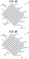
- FIGS. 4A and 4B are partial side views of two embodiments of the sleeve 120 in a state in which the average angle of the cords 121 constituting the sleeve 120 with respect to the axial direction D AX of the actuator is 45 degrees.
- an error range of ⁇ 1 degree is allowed when measuring the angle of the cords 121.
- the ratio (S2/S1) of the total area (S2) of the gaps 122 of the cords 121 constituting the sleeve 120 to the area (S1) of the outer surface of the actuator body 100 is 35% or less, preferably 32% or less, more preferably 30% or less, further preferably 25% or less, and particularly preferably 20% or less, as illustrated in FIGS. 4A and 4B .
- the ratio (S2/S1) of the total area (S2) of the gaps 122 of the cords 121 constituting the sleeve 120 to the area (S1) of the outer surface of the actuator body 100 being 35% or less in a state in which the average angle ⁇ 3 of the cords 121 constituting the sleeve 120 with respect to the axial direction D AX of the actuator is 45 degrees, i.e. in a state in which the average intersection angle of the cords 121 is 90 degrees, the load on the tube 110 is reduced, and the durability of the actuator is improved.
- No lower limit is placed on the ratio (S2/S1), but the ratio (S2/S1) is preferably 5% or more from the perspective of the operation length of the actuator.
- the total area (S2) of the gaps 122 of the cords 121 constituting the sleeve 120 can be adjusted by selecting the method of weaving the sleeve 120, the diameter, material, and driving density of the cords 121 used, etc.
- the total area (S2) of the gaps 122 of the cords 121 constituting the sleeve 120 is measured after adjusting the load on the actuator so that the average angle ⁇ 3 of the cords 121 constituting the sleeve 120 with respect to the axial direction D AX of the actuator is 45 degrees with an air pressure of 5 MPa.
- evaluation is performed in a region in which the diameter of the sleeve 120 is within a range of -5% with respect to the maximum diameter of the sleeve 120, and the ratio (S2/S1) is calculated where S2 is the total area of the gaps 122 in the region and S1 is the area of the outer surface of the actuator body 100 in the region.
- the area of each of the gaps 122 of the cords 121 constituting the sleeve 120 corresponds to the area in which there is no cord 121 and the tube 110 located inside is exposed when the sleeve is seen from outside.
- each of the average angles ⁇ 1 , ⁇ 2 , and ⁇ 3 with respect to the axial direction D AX of the actuator denotes the acute angle between the cords 121 and the axial direction D AX of the actuator.
- the cords 121 constituting the sleeve 120 are preferably fiber cords made of at least one fiber material selected from polyamide fiber such as aramid fiber (aromatic polyamide fiber), polyhexamethylene adipamide (nylon 6,6) fiber, and polycaprolactam (nylon 6) fiber, polyester fiber such as polyethylene terephthalate (PET) fiber and polyethylene naphthalate (PEN) fiber, polyurethane fiber, rayon, acrylic fiber, and polyolefin fiber.
- polyamide fiber such as aramid fiber (aromatic polyamide fiber), polyhexamethylene adipamide (nylon 6,6) fiber, and polycaprolactam (nylon 6) fiber
- polyester fiber such as polyethylene terephthalate (PET) fiber and polyethylene naphthalate (PEN) fiber
- PET polyethylene terephthalate
- PEN polyethylene naphthalate
- polyurethane fiber rayon, acrylic fiber, and polyolefin fiber.
- cords made of aramid fiber are particularly prefer
- the cords 121 are not limited to these types of fiber cords.
- cords made of high-strength fiber such as poly(paraphenylene benzobisoxazole) (PBO) fiber or metal cords formed by ultrafine filaments may be used.
- PBO poly(paraphenylene benzobisoxazole)
- the foregoing fiber cords or metal cords may have their surfaces coated with rubber, a mixture of thermosetting resin and latex, or the like.
- the coefficient of friction of the surfaces of the cords can be reduced moderately while enhancing the durability of the cords.
- the solid content in the mixture of thermosetting resin and latex is preferably 15 mass% or more and 50 mass% or less, and more preferably 20 mass% or more and 40 mass% or less.
- thermosetting resin include phenol resin, resorcin resin, and urethane resin.
- latex include vinylpyridine (VP) latex, styrene-butadiene rubber (SBR) latex, and acrylonitrile-butadiene rubber (NBR) latex.
- the sleeve 120 is preferably formed by alternately crossing every two cords 121 of a cord group 121A oriented in one direction and every two cords 121 of a cord group 121B that crosses the cord group 121A where the crossing position is shifted by one cord, i.e. the sleeve 120 is preferably formed by twill weave (twill), as illustrated in FIGS. 3A and 4A .
- the load on the tube 110 is further reduced, and the durability of the actuator is further improved.
- the sleeve 120 is also preferably formed by alternately crossing every one cord 121 of the cord group 121A oriented in one direction and every one cord 121 of the cord group 121B that crosses the cord group 121A, i.e. the sleeve 120 is preferably formed by plain weave, as illustrated in FIGS. 3B and 4B .
- the load on the tube 110 is further reduced, and the durability of the actuator is further improved.
- the sleeve 120 is also preferably formed by basket weaving the cords 121. In this case, too, the load on the tube 110 is further reduced, and the durability of the actuator is further improved. Although no limit is placed on the number of cords paralleled in basket weave, in the present disclosure it is preferable to parallel two cords and drive other two cords paralleled separately.
- the breaking strength of the cords 121 constituting the sleeve 120 is preferably 200 N or more per cord, more preferably in a range of 250 N per cord to 1000 N per cord, further preferably in a range of 300 N per cord to 1000 N per cord, still further preferably in a range of 500 N per cord to 1000 N per cord, and particularly preferably in a range of 600 N per cord to 1000 N per cord.
- the load on the tube 110 is further reduced, and the durability of the actuator is further improved.
- the breaking elongation of the cords 121 constituting the sleeve 120 is preferably 2.0% or more, and more preferably in a range of 3.0% to 6.0%. In this case, the load on the tube 110 is further reduced, and the durability of the actuator is further improved.
- the diameter of the cords 121 constituting the sleeve 120 is preferably 0.3 mm to 1.5 mm, more preferably 0.4 mm to 1.5 mm, further preferably 0.5 mm to 1.5 mm, still further preferably 0.6 mm to 1.3 mm, and particularly preferably 0.6 mm to 1.0 mm.
- the load on the tube 110 is further reduced, and the durability of the actuator is further improved.
- the driving density of the cords 121 constituting the sleeve 120 is preferably 6.8 cords/cm to 25.5 cords/cm, more preferably 10.0 cords/cm to 23.5 cords/cm, and further preferably 10.0 cords/cm to 20.0 cords/cm.
- the load on the tube 110 is further reduced, and the durability of the actuator is further improved.
- the thickness t (mm) of the tube 110, the diameter d (mm) of the cords 121 constituting the sleeve 120, the average angle ⁇ 1 of the cords 121 constituting the sleeve 120 with respect to the axial direction D AX of the actuator in a no-load and no-pressure state, and the average angle ⁇ 2 of the cords 121 constituting the sleeve 120 with respect to the axial direction D AX of the actuator during contraction of the actuator satisfy the following Formula (1): t > sin ⁇ 2 ⁇ sin 2 ⁇ 2 sin 2 ⁇ 1 ⁇ 1 sin 2 ⁇ 1 ⁇ 1 2 cos ⁇ 2 ⁇ d
- the thickness t (mm) of the tube 110, the diameter d (mm) of the cords 121 constituting the sleeve 120, the average angle ⁇ 1 of the cords 121 constituting the sleeve 120 with respect to the axial direction D AX of the actuator in a no-load and no-pressure state, and the average angle ⁇ 2 of the cords 121 constituting the sleeve 120 with respect to the axial direction D AX of the actuator during contraction of the actuator satisfy the following Formula (2): t > sin 2 ⁇ 2 sin ⁇ 2 sin 2 2 ⁇ 1 ⁇ d
- the twist coefficient K of the cords 121 constituting the sleeve 120 is preferably 0.14 to 0.50, and more preferably 0.16 to 0.50.
- the twist coefficient K of the cords 121 constituting the sleeve 120 is 0.14 or more, the load on the fibers is reduced, and the durability of the actuator is further improved. In the case where the twist coefficient K of the cords 121 constituting the sleeve 120 is 0.50 or less, the load on the tube is reduced, and the durability of the actuator is further improved.
- the twist coefficient K of the cords 121 can be adjusted by selecting the density or fineness of the original yarns used or adjusting the first twist count when forming the cords.
- the ratio (Ti/D) between the first twist count T 1 (turns/10 cm) and the fineness D (dtex) of the original yarns constituting the cords 121 per yarn is preferably 0.004 to 0.03, and more preferably 0.004 to 0.02. In this case, the load on the tube 110 is further reduced, and the durability of the actuator is further improved.
- the ratio (T 1 /T 2 ) between the first twist count T 1 (turns/10 cm) and the final twist count T 2 (turns/10 cm) is preferably 0.8 to 1.2, and more preferably 0.9 to 1.1. In this case, the load on the tube 110 is further reduced, and the durability of the actuator is further improved.
- the fineness D of the original yarns constituting the cords 121 per yarn is preferably 800 dtex to 5000 dtex, more preferably 800 dtex to 4000 dtex, further preferably 1000 dtex to 4000 dtex, still further preferably 1500 dtex to 4000 dtex, and particularly preferably 2000 dtex to 4000 dtex.
- the load on the tube 110 is further reduced, and the durability of the actuator is further improved.
- the first twist count T 1 is preferably 3.2 turns/10 cm to 150 turns/10 cm, more preferably 10 turns/10 cm to 36 turns/10 cm, and further preferably 10 turns/10 cm to 30 turns/10 cm. In this case, the load on the tube 110 is further reduced, and the durability of the actuator is further improved.
- the final twist count T 2 is preferably 2.6 turns/10 cm to 180 turns/10 cm, more preferably 10 turns/10 cm to 36 turns/10 cm, and further preferably 10 turns/10 cm to 30 turns/10 cm. In this case, the load on the tube 110 is further reduced, and the durability of the actuator is further improved.
- the number of original yarns twisted is preferably 2 to 4, and particularly preferably 2.
- the load on the tube 110 is further reduced, and the durability of the actuator is further improved.
- the fineness D of the original yarns constituting the cords 121 per yarn is 800 dtex to 5000 dtex
- the first twist count T 1 is 3.2 turns/10 cm to 150 turns/10 cm
- the final twist count T 2 is 2.6 turns/10 cm to 180 turns/10 cm
- the number of original yarns twisted is 2 to 4.
- the load on the tube 110 is particularly reduced, and the durability of the actuator is significantly improved.
- the method of producing the cords 121 is not limited.
- a twisted yarn cord can be obtained by subjecting original yarns to first twist and then subjecting a plurality of first twisted yarns to final twist in the opposite direction.
- a twisted yarn cord can be obtained by paralleling an original yarn and twisting it in one direction.
- first twist count T 1 denotes the twist count when twisting one original yarn.
- the final twist count T 2 (turns/10 cm) in Formula (1) is replaced with the first twist count T 1 (turns/10 cm). That is, in the case where the cords 121 have a single-twist structure, T 2 in Formula (1) denotes the twist count when twisting one original yarn.
- the sealing mechanism 200 seals the end of the actuator body 100 in the axial direction D AX .
- the sealing mechanism 200 includes the sealing member 210, a first locking ring 220, and the caulking member 230.
- the sealing member 210 includes a body portion 211 and a flange portion 212.
- metal such as stainless steel is preferably used.
- the material of the sealing member 210 is, however, not limited to metal, and may be a hard plastic material or the like.
- the body portion 211 has a circular tube shape.
- a passage hole 215 through which the working fluid passes is formed in the body portion 211.
- the passage hole 215 communicates with the passage hole 410 (see FIG. 1 ).
- the body portion 211 is inserted into the tube 110.
- the flange portion 212 connects to the body portion 211, and is located closer to the end of the pneumatic actuator 10 in the axial direction D AX than the body portion 211.
- the flange portion 212 has a larger outer diameter along the radial direction D R than the body portion 211.
- the flange portion 212 locks the tube 110 into which the body portion 211 is inserted and the first locking ring 220.
- a recess and projection portion 213 is formed on the outer peripheral surface of the body portion 211.
- the recess and projection portion 213 prevents the tube 110 into which the body portion 211 is inserted, from slipping. It is preferable that three or more projections are formed by the recess and projection portion 213.
- a first small diameter portion 214 smaller in outer diameter than the body portion 211 is formed in a part of the body portion 211 near the flange portion 212.
- the shape of the first small diameter portion 214 will be described in detail later, with reference to FIG. 5 and the subsequent drawings.
- the first locking ring 220 locks the sleeve 120. Specifically, the sleeve 120 is folded outward in the radial direction D R via the first locking ring 220 (not illustrated in FIG. 2 , see FIG. 5 ).
- the outer diameter of the first locking ring 220 is larger than the outer diameter of the body portion 211.
- the first locking ring 220 locks the sleeve 120 at a position of the first small diameter portion 214 of the body portion 211. That is, the first locking ring 220 locks the sleeve 120 at a position that is on the outer side of the body portion 211 in the radial direction D R and adjacent to the flange portion 212.
- the first locking ring 220 is divided into two parts, in order to lock the sleeve 120 at the first small diameter portion 214 smaller than the body portion 211.
- the first locking ring 220 is, however, not limited to a two-division shape, and may be divided into more parts. Moreover, part of the divided parts may be connected rotatably.
- the same material as the sealing member 210 such as metal or a hard plastic material, may be used.
- the caulking member 230 caulks the actuator body 100, together with the sealing member 210.
- metal such as an aluminum alloy, brass, or iron may be used.
- the pressed mark 231 illustrated in FIG. 1 is formed on the caulking member 230 as a result of the caulking member 230 being caulked by a caulking jig.
- Embodiments of the sealing mechanism 200 will be described below, with reference to FIGS. 5 to 12 .
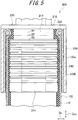
- FIG. 5 is a partial cross-sectional view along the axial direction D AX of the pneumatic actuator 10 including the sealing mechanism 200 according to Embodiment 1-1.
- the sealing member 210 includes the first small diameter portion 214 whose outer diameter is smaller than the outer diameter of the body portion 211, as mentioned above.
- the first locking ring 220 is located on the outer side of the first small diameter portion 214 in the radial direction D R .
- the inner diameter R1 of the first locking ring 220 is smaller than the outer diameter R3 of the body portion 211.
- the outer diameter R2 of the first locking ring 220 may be smaller than the outer diameter R3 of the body portion 211.
- the body portion 211 is inserted into the tube 110 until the tube 110 comes into contact with the flange portion 212.
- the sleeve 120 is folded outward in the radial direction D R via the first locking ring 220.
- the sleeve 120 thus includes a first folded portion 120a folded via the first locking ring 220 at the end in the axial direction D AX .
- the sleeve 120 includes: a sleeve body portion 120b covering the outer peripheral surface of the tube 110; and the first folded portion 120a located on the outer peripheral side of the sleeve body portion 120b as a result of being folded at the end of the sleeve body portion 120b in the axial direction D AX .
- the first folded portion 120a is adhered to the sleeve body portion 120b located on the outer side of the tube 110 in the radial direction D R .
- an adhesion layer 240 is formed between the sleeve body portion 120b and the first folded portion 120a, and adheres the sleeve body portion 120b and the first folded portion 120a to each other.
- an appropriate adhesive may be used depending on the type of the cords constituting the sleeve 120.
- the adhesion layer 240 is optional, and the first folded portion 120a may not be adhered to the sleeve body portion 120b.
- the caulking member 230 is larger than the outer diameter of the body portion 211 of the sealing member 210.
- the caulking member 230 having the body portion 211 inserted therein is caulked by a jig.
- the caulking member 230 caulks the actuator body 100, together with the sealing member 210.
- the caulking member 230 caulks the tube 110 into which the body portion 211 is inserted, the sleeve body portion 120b, and the first folded portion 120a. That is, the caulking member 230 caulks the tube 110, the sleeve body portion 120b, and the first folded portion 120a, together with the sealing member 210.
- FIG. 6 is a partial cross-sectional view along the axial direction D AX of the pneumatic actuator 10 including the sealing mechanism 200 according to Embodiment 1-2. The differences from Embodiment 1-1 will be mainly described below.
- a sheet-like elastic member is provided between the first folded portion 120a of the sleeve 120 and the caulking member 230.
- a rubber sheet 250 is provided between the first folded portion 120a and the caulking member 230.
- the rubber sheet 250 is provided so as to cover the outer peripheral surface of the cylindrical first folded portion 120a.
- the type of the rubber sheet 250 is not limited. For example, the same type of rubber as the tube 110 may be used.
- the caulking member 230 caulks not only the actuator body 100 but also the rubber sheet 250, together with the sealing member 210.
- FIG. 7 is a partial cross-sectional view along the axial direction D AX of the pneumatic actuator 10 including the sealing mechanism 200 according to Embodiment 1-3.
- a rubber sheet 260 is used instead of the adhesion layer 240 in Embodiment 1-1.
- the rubber sheet 260 is a sheet-like elastic member, and is provided between the sleeve body portion 120b and the first folded portion 120a.
- the rubber sheet 260 may be made of the same type of rubber as the rubber sheet 250.
- FIG. 8 is a partial cross-sectional view along the axial direction D AX of the pneumatic actuator 10 including a sealing mechanism 200A according to Embodiment 2-1.
- the sealing mechanism 200A is used instead of the sealing mechanism 200 in Embodiment 1.
- the sealing mechanism 200A differs from the sealing mechanism 200 in that it does not include the first small diameter portion 214 included in the sealing member 210.
- the sealing mechanism 200A includes a sealing member 210A, a first locking ring 220A, and a caulking member 230A.
- a body portion 211A of the sealing member 210A is inserted into the tube 110. Since the sealing member 210A does not include the first small diameter portion 214 included in the sealing member 210, the outer diameter of the first locking ring 220A is larger than the outer diameter of the body portion 211A. Hence, the first locking ring 220A is locked by the flange portion 212A and the caulking member 230A.
- the caulking member 230A is not in contact with the flange portion 212A. That is, the part of the first locking ring 220A via which the sleeve 120 is folded is exposed to the outside. Moreover, because the outer diameter of the first locking ring 220A is larger than the outer diameter of the body portion 211A, the first locking ring 220A need not be divided like the first locking ring 220 in Embodiment 1.
- the adhesion layer 240 is formed between the sleeve body portion 120b and the first folded portion 120a, as in Embodiment 1-1.
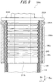
- FIG. 9 is a partial cross-sectional view along the axial direction D AX of the pneumatic actuator 10 including the sealing mechanism 200A according to Embodiment 2-2. The differences from Embodiment 2-1 will be mainly described below.
- a sheet-like elastic member is provided between the first folded portion 120a of the sleeve 120 and the caulking member 230A.
- a rubber sheet 250A is provided between the first folded portion 120a and the caulking member 230A.
- the rubber sheet 250A is provided so as to cover the outer peripheral surface of the cylindrical first folded portion 120a, as with the rubber sheet 250 in Embodiment 1-2.
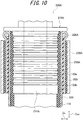
- FIG. 10 is a partial cross-sectional view along the axial direction D AX of the pneumatic actuator 10 including the sealing mechanism 200A according to Embodiment 2-3.
- a rubber sheet 260 is used instead of the adhesion layer 240 in Embodiment 2-1.
- the rubber sheet 260 is a sheet-like elastic member, and is provided between the sleeve body portion 120b and the first folded portion 120a, as in Embodiment 1-3.
- FIG. 11 is a partial cross-sectional view along the axial direction D AX of the pneumatic actuator 10 including a sealing mechanism 200B according to Embodiment 3-1.
- Embodiment 3 (3-1 and 3-2), two locking rings are used.
- the sealing mechanism 200B includes a sealing member 210B, a first locking ring 220B, a caulking member 230B, and a second locking ring 270.
- the sealing mechanism 200B includes the second locking ring 270 in addition to the first locking ring 220B.
- the second locking ring 270 locks the sleeve 120 at a position that is on the outer side of a body portion 211B in the radial direction D R and closer to the center of the actuator body 100 in the axial direction D AX than the first locking ring 220B.
- the sealing member 210B includes a second small diameter portion 216B whose outer diameter is smaller than the outer diameter of the body portion 211B.
- the second locking ring 270 is located on the outer side of the second small diameter portion 216B in the radial direction D R .
- the inner diameter of the second locking ring 270 is preferably smaller than the outer diameter of the body portion 211B.
- the outer diameter of the second locking ring 270 may be smaller than the outer diameter of the body portion 211B.
- the second locking ring 270 is locked by the second small diameter portion 216B.
- the sleeve 120 includes a second folded portion 120c folded via the second locking ring 270.
- the second folded portion 120c connects to the first folded portion 120a. That is, the second folded portion 120c is located on the outer peripheral side of the first folded portion 120a as a result of being folded at the end of the first folded portion 120a in the axial direction D AX .
- the sleeve 120 forms the first folded portion 120a as a result of being folded via the first locking ring 220B toward the center of the actuator body 100 in the axial direction D AX .
- the sleeve 120 further forms the second folded portion 120c as a result of the first folded portion 120a being folded toward the end of the actuator body 100 in the axial direction D AX .
- the caulking member 230B caulks the tube 110 into which the body portion 211B is inserted, the sleeve body portion 120b located on the outer side of the tube 110 in the radial direction D R , the first folded portion 120a, and the second folded portion 120c, together with the sealing member 210B.
- the same rubber sheet 260 as in Embodiment 1-3 is provided between the sleeve body portion 120b and the first folded portion 120a.
- a sheet-like elastic member is provided between the first folded portion 120a and the second folded portion 120c.
- a rubber sheet 280 is provided between the first folded portion 120a and the second folded portion 120c. The rubber sheet 280 is provided so as to cover the outer peripheral surface of the cylindrical first folded portion 120a.
- a rubber sheet 290 having approximately the same shape as the rubber sheet 250 in Embodiment 1-3 is provided between the second folded portion 120c and the caulking member 230B.
- the rubber sheet 290 is provided so as to cover the outer peripheral surface of the cylindrical second folded portion 120c.
- FIG. 12 is a partial cross-sectional view along the axial direction D AX of the pneumatic actuator 10 including a sealing mechanism 200C according to Embodiment 3-2. The differences from Embodiment 3-1 will be mainly described below.
- a sealing member 210C not including the first small diameter portion 214B and the second small diameter portion 216B is used.
- the sealing member 210C includes a body portion 211C.
- the sealing member 210C does not include the first small diameter portion 214B and the second small diameter portion 216B included in the sealing member 210B, so that the inner diameter of a first locking ring 220C and the inner diameter of a second locking ring 270C are each larger than the outer diameter of the body portion 211C.
- a caulking member 230C is located between the first locking ring 220C and the second locking ring 270C in the axial direction D AX . That is, the part of the first locking ring 220C and the part of the second locking ring 270C via which the sleeve 120 is folded are exposed to the outside.
- a rubber sheet 281 having approximately the same shape as the rubber sheet 280 in Embodiment 3-1 is provided between the first folded portion 120a and the second folded portion 120c.
- a rubber sheet 291 having approximately the same shape as the rubber sheet 290 in Embodiment 3-1 is provided between the second folded portion 120c of the sleeve 120 and the caulking member 230C.
- a rubber composition was prepared by kneading, with a Banbury mixer, 45 parts by mass of high-nitrile NBR (acrylonitrile-butadiene rubber, "N220S” produced by JSR Corporation), 35 parts by mass of intermediate-high-nitrile NBR (acrylonitrile-butadiene rubber, "N230S” produced by JSR Corporation), 20 parts by mass of BR (butadiene rubber, "UBEPOL® BR150” (UBEPOL is a registered trademark in Japan, other countries, or both) produced by Ube Industries, Ltd.), 50 parts by mass of carbon black ("Seast 3" produced by Tokai Carbon Co., Ltd.), 1 part by mass of stearic acid (“Stearic Acid 50S” produced by New Japan Chemical Co., Ltd.), 2 parts by mass of an age resistor ("NOCRAC 6C” produced by Ouchi Shinko Chemical Industrial Co., Ltd.), 10 parts by mass of resin ("Quintone 100" produced by Zeon Corporation), 8 parts by mass of a plastic
- the obtained rubber composition was processed by an extrusion molding machine, to produce a cylindrical tube of 300 mm in length.
- the outer diameter and the thickness of each produced tube are listed in Table 1.
- 64 aramid fiber cords of the specifications listed in Table 1 were woven to prepare a cylindrical sleeve in a mesh shape. Each aramid fiber cord was produced by subjecting aramid fibers of original yarns to first twist and further subjecting them to final twist. The sleeve was a mesh-shaped tubular body with 64 aramid fiber cords being observed on the circumference in cross-section.
- the sleeve was a mesh-shaped tubular body formed by alternately weaving 32 aramid fiber cords arranged at regular spacing, in parallel, and in a spiral shape and other 32 aramid fiber cords intersecting obliquely with the 32 aramid fiber cords and arranged at regular spacing, in parallel, and in a spiral shape. As illustrated in FIG. 3A , every two cords of one cord group and every two cords of the other cord group were alternately crossed, with the crossing position being shifted by one cord (twill weave (twill)).
- the foregoing tube and mesh-shaped sleeve were used to produce an actuator having the structure illustrated in FIGS. 1 and 2 .
- Air was used as the working fluid of the tube incorporated in the actuator.
- the angle of the cords constituting the sleeve of the produced actuator and the durability of the actuator were evaluated by the following methods.
- the angle of the cords constituting the sleeve with respect to the axial direction of the actuator was calculated in the following manner:
- the angle of the cords was measured in a no-load and no-pressure state and during contraction of the actuator under a prescribed load and air pressure (internal pressure).
- the former is indicated as “initial cord angle ⁇ 1 " and the latter as “cord angle during contraction ⁇ 2 " in the table.
- the load on the actuator was adjusted so that the average angle of the cords constituting the sleeve with respect to the axial direction of the actuator was 45 degrees with an air pressure of 5 MPa, a photograph was taken in the same way as "Evaluation method for angle of cords constituting sleeve", and the total area (S2) of the gaps of the cords was measured. Using this value (S2), the ratio (S2/S1) was calculated from the value of the area (S1) of the outer surface of the actuator body. The ratio (S2/S1) is indicated as "gap rate during contraction (S2/S1)" in the table. In the measurement of the angle of the cords, the error range was ⁇ 1 degree.
- Air was injected into the tube as the working fluid.
- the working fluid injection operation was performed so that the pressure of the working fluid in the tube alternated between 0 MPa and 5 MPa at intervals of 3 seconds, and the number of times until the tube cracked and the actuator function could no longer be exhibited was measured.
- the result is indicated as an index, with the number of times in Example 1 being 100. A higher index value corresponds to higher durability.
- the pneumatic actuators according to the present disclosure had high durability.
Landscapes
- Engineering & Computer Science (AREA)
- Physics & Mathematics (AREA)
- Fluid Mechanics (AREA)
- Mechanical Engineering (AREA)
- General Engineering & Computer Science (AREA)
- Chemical & Material Sciences (AREA)
- Analytical Chemistry (AREA)
- Actuator (AREA)
Abstract

Description
- The present disclosure relates to a pneumatic actuator.
- Conventionally, as an actuator for expanding and contracting a tube, a pneumatic actuator (so-called McKibben type) including: a rubber tube (tubular body) that expands and contracts using air as a working fluid; and a sleeve (braided reinforcing structure) that covers the outer peripheral surface of the tube is widely used (for example, see PTL 1).
- Both ends of an actuator body formed by the tube and the sleeve are caulked using sealing members made of metal.
- The sleeve is a cylindrical structure formed by weaving cords of high-tensile fiber such as polyamide fiber or metal, and regulates the expansion movement of the tube within a predetermined range.
- Such a pneumatic actuator is used in various fields. The pneumatic actuator is particularly suitable for use as an artificial muscle in nursing or healthcare equipment.
- PTL 1:
JP S61-236905 A - However, the foregoing conventional actuator does not necessarily have high strength (withstanding pressure). Particularly in the case where the sleeve is not designed appropriately, the load on the tube increases. There is thus room for improvement in durability.
- It could therefore be helpful to provide a pneumatic actuator having improved durability as an actuator that uses gas as a working fluid.
- We thus provide the following.
- A pneumatic actuator according to the present disclosure comprises an actuator body including: a cylindrical tube configured to expand and contract by air pressure; and a sleeve that is a cylindrical structure formed by weaving cords oriented in predetermined directions and covers an outer peripheral surface of the tube,
wherein in a no-load and no-pressure state, an average angle of the cords constituting the sleeve with respect to an axial direction of the actuator is 20 degrees or more and less than 45 degrees, and
in a state in which the average angle of the cords constituting the sleeve with respect to the axial direction of the actuator is 45 degrees with an air pressure of 5 MPa, a ratio S2/S1 of a total area S2 of gaps of the cords constituting the sleeve to an area S1 of an outer surface of the actuator body is 35% or less. - In such a pneumatic actuator according to the present disclosure, the sleeve is designed appropriately. Hence, the load on the tube is reduced, and the durability is improved.
- In a preferred embodiment of the pneumatic actuator according to the present disclosure, the cords constituting the sleeve are made of at least one fiber material selected from polyamide fiber, polyester fiber, polyurethane fiber, rayon, acrylic fiber, and polyolefin fiber. In this case, the durability of the actuator is further improved.
- In another preferred embodiment of the pneumatic actuator according to the present disclosure, the sleeve is formed by alternately crossing respectively every one cord or every two cords of a cord group oriented in one direction and every one cord or every two cords of a cord group that crosses the cord group, with a position at which cords cross each other is shifted by one cord. In this case, the durability of the actuator is further improved.
- In another preferred embodiment of the pneumatic actuator according to the present disclosure, the sleeve is formed by twill weaving or plain weaving the cords. In this case, too, the durability of the actuator is further improved.
- In another preferred embodiment of the pneumatic actuator according to the present disclosure, a breaking strength of the cords constituting the sleeve is 200 N or more per cord. In this case, the durability of the actuator is further improved. In the present disclosure, the breaking strength of the cords is measured in accordance with JIS L1017.
- In another preferred embodiment of the pneumatic actuator according to the present disclosure, a breaking elongation of the cords constituting the sleeve is 2.0% or more. In this case, the durability of the actuator is further improved. In the present disclosure, the breaking elongation of the cords is measured in accordance with JIS L1017.
- In another preferred embodiment of the pneumatic actuator according to the present disclosure, a diameter of the cords constituting the sleeve is 0.3 mm to 1.5 mm. In this case, the durability of the actuator is further improved.
- In another preferred embodiment of the pneumatic actuator according to the present disclosure, a driving density of the cords constituting the sleeve is 6.8 cords/cm to 25.5 cords/cm. In this case, the durability of the actuator is further improved.
- In another preferred embodiment of the pneumatic actuator according to the present disclosure, a thickness t of the tube in mm, a diameter d of the cords constituting the sleeve in mm, an average angle Θ1 of the cords constituting the sleeve with respect to the axial direction of the actuator in the no-load and no-pressure state, and an average angle Θ2 of the cords constituting the sleeve with respect to the axial direction of the actuator during contraction of the actuator satisfy the following Formula (1):

- In this case, the durability of the actuator is further improved.
- Herein, the average angle Θ2 of the cords constituting the sleeve with respect to the axial direction of the actuator during contraction of the actuator is a value measured with a load of 2.5 kN and an air pressure of 5 MPa.
- Further preferably, the thickness t of the tube in mm, the diameter d of the cords constituting the sleeve in mm, the average angle Θ1 of the cords constituting the sleeve with respect to the axial direction of the actuator in the no-load and no-pressure state, and the average angle Θ2 of the cords constituting the sleeve with respect to the axial direction of the actuator during contraction of the actuator satisfy the following Formula (2):

- In this case, the durability of the actuator is even further improved.
- In another preferred embodiment of the pneumatic actuator according to the present disclosure, a twist coefficient K of the cords constituting the sleeve is 0.14 to 0.50, the twist coefficient K being defined by the following Formula (3):

- Preferably, in the pneumatic actuator according to the present disclosure, in the cords constituting the sleeve, a ratio Ti/D between a first twist count T1 in turns/10 cm and a fineness D of original yarns constituting the cords per yarn in dtex is 0.004 to 0.03. In this case, the durability of the actuator is further improved.
- Preferably, in the pneumatic actuator according to the present disclosure, in the cords constituting the sleeve, a ratio T1/T2 between a first twist count T1 in turns/10 cm and a final twist count T2 in turns/10 cm is 0.8 to 1.2. In this case, the durability of the actuator is further improved.
- Preferably, in the pneumatic actuator according to the present disclosure, in the cords constituting the sleeve, a fineness D of original yarns constituting the cords per yarn is 800 dtex to 5000 dtex, a first twist count T1 is 3.2 turns/10 cm to 150 turns/10 cm, a final twist count T2 is 2.6 turns/10 cm to 180 turns/10 cm, and a number of original yarns twisted is 2 to 4. In this case, the durability of the actuator is further improved.
- In another preferred embodiment of the pneumatic actuator according to the present disclosure, a thickness of the tube is 1.0 mm to 6.0 mm in the no-load and no-pressure state. In this case, the durability of the actuator is further improved.
- It is therefore possible to provide a pneumatic actuator having improved durability.
- In the accompanying drawings:
-
FIG. 1 is a side view of an embodiment of apneumatic actuator 10; -
FIG. 2 is a partial exploded perspective view of the embodiment of thepneumatic actuator 10; -
FIG. 3A is a partial side view of an embodiment of asleeve 120 in a no-load and no-pressure state andFIG. 3B is a partial side view of another embodiment of thesleeve 120 in a no-load and no-pressure state; -
FIG. 4A is a partial side view of an embodiment of thesleeve 120 in a state in which the average angle ofcords 121 constituting thesleeve 120 with respect to the axial direction of the actuator is 45 degrees andFIG. 4B is a partial side view of another embodiment of thesleeve 120 in a state in which the average angle of thecords 121 constituting thesleeve 120 with respect to the axial direction of the actuator is 45 degrees; -
FIG. 5 is a partial cross-sectional view along the axial direction DAX of thepneumatic actuator 10 including asealing mechanism 200 according to Embodiment 1-1; -
FIG. 6 is a partial cross-sectional view along the axial direction DAX of thepneumatic actuator 10 including thesealing mechanism 200 according to Embodiment 1-2; -
FIG. 7 is a partial cross-sectional view along the axial direction DAX of thepneumatic actuator 10 including thesealing mechanism 200 according to Embodiment 1-3; -
FIG. 8 is a partial cross-sectional view along the axial direction DAX of thepneumatic actuator 10 including asealing mechanism 200A according to Embodiment 2-1; -
FIG. 9 is a partial cross-sectional view along the axial direction DAX of thepneumatic actuator 10 including thesealing mechanism 200A according to Embodiment 2-2; -
FIG. 10 is a partial cross-sectional view along the axial direction DAX of thepneumatic actuator 10 including thesealing mechanism 200A according to Embodiment 2-3; -
FIG. 11 is a partial cross-sectional view along the axial direction DAX of thepneumatic actuator 10 including asealing mechanism 200B according to Embodiment 3-1; and -
FIG. 12 is a partial cross-sectional view along the axial direction DAX of thepneumatic actuator 10 including a sealing mechanism 200C according to Embodiment 3-2. - A pneumatic actuator according to the present disclosure will be described in detail below based on embodiments, with reference to the drawings. The same functions or structures are given the same or similar reference signs, and their description is omitted as appropriate.
-
FIG. 1 is a side view of apneumatic actuator 10 according to this embodiment. As illustrated inFIG. 1 , thepneumatic actuator 10 includes anactuator body 100, asealing mechanism 200, and asealing mechanism 300.Connection portions 20 are provided at both ends of thepneumatic actuator 10. - The
actuator body 100 includes atube 110 and asleeve 120. A working fluid flows into theactuator body 100 via a fitting 400 and apassage hole 410. The actuator according to the present disclosure is a pneumatic actuator, and gas is used as the working fluid. Examples of the gas include air and nitrogen. - As a result of the working fluid flowing into the
tube 110, theactuator body 100 contracts in the axial direction DAX of theactuator body 100 and expands in the radial direction DR of theactuator body 100. As a result of the working fluid flowing out of thetube 110, theactuator body 100 expands in the axial direction DAX of theactuator body 100 and contracts in the radial direction DR of theactuator body 100. With such shape changes of theactuator body 100, thepneumatic actuator 10 functions as an actuator. - The
pneumatic actuator 10 is so-called McKibben type, and cannot only be used for an artificial muscle but also be suitable for use as a limb (upper limb, lower limb, etc.) of a robot required to have higher capability (contraction force). A member forming the limb or the like is connected to eachconnection portion 20. - The sealing
mechanisms actuator body 100 in the axial direction DAX. Specifically, thesealing mechanism 200 includes a sealingmember 210 and acaulking member 230. The sealingmember 210 seals an end of theactuator body 100 in the axial direction DAX. Thecaulking member 230 caulks theactuator body 100, together with the sealingmember 210. Apressed mark 231, i.e. a mark as a result of caulking thecaulking member 230 by a jig, is formed on the outer peripheral surface of thecaulking member 230. - The difference between the sealing
mechanisms fittings 400 and 500 (and passage holes 410 and 510) have different roles. - The fitting 400 provided in the
sealing mechanism 200 protrudes so that a driving pressure source of thepneumatic actuator 10, specifically, a hose (pipe line) connected to a compressor for the working fluid, can be attached to the fitting 400. The working fluid flowing in through the fitting 400 passes through thepassage hole 410 and enters into theactuator body 100, specifically, into thetube 110. - The fitting 500 provided in the
sealing mechanism 300 protrudes so as to be used for degassing when the working fluid is injected into the actuator. In an initial working stage of the actuator, when the working fluid is injected into the actuator, gas existing inside the actuator is discharged from the fitting 500 through thepassage hole 510. -
FIG. 2 is a partial exploded perspective view of thepneumatic actuator 10. As illustrated inFIG. 2 , thepneumatic actuator 10 includes theactuator body 100 and thesealing mechanism 200. - The
actuator body 100 includes thetube 110 and thesleeve 120, as mentioned above. - The
tube 110 is a cylindrical tubular body that expands and contracts by air pressure. Since thetube 110 repeats contraction and expansion by the working fluid, thetube 110 is made of an elastic material such as rubber. - In a no-load and no-pressure state, the thickness of the
tube 110 is preferably in a range of 1.0 mm to 6.0 mm, and more preferably in a range of 1.4 mm to 5.0 mm. If the thickness of thetube 110 is 1.0 mm or more, the strength of thetube 110 increases, and thetube 110 is kept from sticking out of gaps of the cords constituting thesleeve 120. Hence, the durability of the actuator is further improved. If the thickness of thetube 110 is 6.0 mm or less, the contraction coefficient of thetube 110 increases, with it being possible to ensure sufficient operation length. - The
tube 110 illustrated inFIGS. 1 and2 has a single-layer structure. In the present disclosure, however, the tube may have a structure of two or more layers. The diameter (outer diameter) of thetube 110 may be selected as appropriate depending on the intended use. - The
sleeve 120 is cylindrical, and covers the outer peripheral surface of thetube 110. Thesleeve 120 is a structure formed by weaving cords oriented in predetermined directions. The oriented cords intersect each other to repeatedly form a rhombus shape. Such a shape allows thesleeve 120 to deform like a pantograph and follow the contraction and expansion of thetube 110 while regulating the contraction and expansion. -
FIGS. 3A and 3B are partial side views of two embodiments of thesleeve 120 in a no-load and no-pressure state. - In the present disclosure, in a no-load and no-pressure state (i.e. initial state), the average angle Θ1 of the
cords 121 constituting thesleeve 120 with respect to the axial direction DAX of the actuator is 20 degrees or more and less than 45 degrees, as illustrated inFIGS. 3A and 3B . As a result of the average angle Θ1 of thecords 121 constituting thesleeve 120 with respect to the axial direction DAX of the actuator being 20 degrees or more in the no-load and no-pressure state, the durability of thesleeve 120 is improved. If the average angle Θ1 of thecords 121 constituting thesleeve 120 with respect to the axial direction DAX of the actuator is more than 45 degrees in the no-load and no-pressure state, the contraction of the actuator during working is small, causing insufficient actuator function. - The average angle Θ1 is preferably 22 degrees or more, and more preferably 23 degrees or more. When the average angle Θ1 is greater, the load on the
tube 110 is lighter, so that damage of the part of thetube 110 not in direct contact with thecords 121 is suppressed. Hence, the actuator function can be maintained for a long period of time. - The average angle Θ1 is preferably 37 degrees or less. If the average angle Θ1 is 37 degrees or less, the contraction coefficient of the actuator increases, with it being possible to ensure sufficient operation length.
- The average angle Θ1 of the
cords 121 constituting thesleeve 120 with respect to the axial direction DAX of the actuator in the initial state can be adjusted, for example, by adjusting the directions of thecords 121 when weaving thesleeve 120 and further adjusting the directions of thecords 121 when shaping thesleeve 120 into a cylinder. -
FIGS. 4A and 4B are partial side views of two embodiments of thesleeve 120 in a state in which the average angle of thecords 121 constituting thesleeve 120 with respect to the axial direction DAX of the actuator is 45 degrees. In the present disclosure, an error range of ±1 degree is allowed when measuring the angle of thecords 121. - In the present disclosure, in a state in which the average angle Θ3 of the
cords 121 constituting thesleeve 120 with respect to the axial direction DAX of the actuator is 45 degrees with an air pressure of 5 MPa, the ratio (S2/S1) of the total area (S2) of thegaps 122 of thecords 121 constituting thesleeve 120 to the area (S1) of the outer surface of theactuator body 100 is 35% or less, preferably 32% or less, more preferably 30% or less, further preferably 25% or less, and particularly preferably 20% or less, as illustrated inFIGS. 4A and 4B . As a result of the ratio (S2/S1) of the total area (S2) of thegaps 122 of thecords 121 constituting thesleeve 120 to the area (S1) of the outer surface of theactuator body 100 being 35% or less in a state in which the average angle Θ3 of thecords 121 constituting thesleeve 120 with respect to the axial direction DAX of the actuator is 45 degrees, i.e. in a state in which the average intersection angle of thecords 121 is 90 degrees, the load on thetube 110 is reduced, and the durability of the actuator is improved. No lower limit is placed on the ratio (S2/S1), but the ratio (S2/S1) is preferably 5% or more from the perspective of the operation length of the actuator. - The total area (S2) of the
gaps 122 of thecords 121 constituting thesleeve 120 can be adjusted by selecting the method of weaving thesleeve 120, the diameter, material, and driving density of thecords 121 used, etc. - In the present disclosure, the total area (S2) of the
gaps 122 of thecords 121 constituting thesleeve 120 is measured after adjusting the load on the actuator so that the average angle Θ3 of thecords 121 constituting thesleeve 120 with respect to the axial direction DAX of the actuator is 45 degrees with an air pressure of 5 MPa. Here, evaluation is performed in a region in which the diameter of thesleeve 120 is within a range of -5% with respect to the maximum diameter of thesleeve 120, and the ratio (S2/S1) is calculated where S2 is the total area of thegaps 122 in the region and S1 is the area of the outer surface of theactuator body 100 in the region. The area of each of thegaps 122 of thecords 121 constituting thesleeve 120 corresponds to the area in which there is nocord 121 and thetube 110 located inside is exposed when the sleeve is seen from outside. - In the present disclosure, each of the average angles Θ1, Θ2, and Θ3 with respect to the axial direction DAX of the actuator denotes the acute angle between the
cords 121 and the axial direction DAX of the actuator. - The
cords 121 constituting thesleeve 120 are preferably fiber cords made of at least one fiber material selected from polyamide fiber such as aramid fiber (aromatic polyamide fiber), polyhexamethylene adipamide (nylon 6,6) fiber, and polycaprolactam (nylon 6) fiber, polyester fiber such as polyethylene terephthalate (PET) fiber and polyethylene naphthalate (PEN) fiber, polyurethane fiber, rayon, acrylic fiber, and polyolefin fiber. In this case, the durability of the sleeve is further improved. Of these, cords made of aramid fiber are particularly preferable from the perspective of the strength of thesleeve 120. - The
cords 121 are not limited to these types of fiber cords. For example, cords made of high-strength fiber such as poly(paraphenylene benzobisoxazole) (PBO) fiber or metal cords formed by ultrafine filaments may be used. - The foregoing fiber cords or metal cords may have their surfaces coated with rubber, a mixture of thermosetting resin and latex, or the like. In the case where the surfaces of the cords are coated with such material, the coefficient of friction of the surfaces of the cords can be reduced moderately while enhancing the durability of the cords.
- The solid content in the mixture of thermosetting resin and latex is preferably 15 mass% or more and 50 mass% or less, and more preferably 20 mass% or more and 40 mass% or less. Examples of the thermosetting resin include phenol resin, resorcin resin, and urethane resin. Examples of the latex include vinylpyridine (VP) latex, styrene-butadiene rubber (SBR) latex, and acrylonitrile-butadiene rubber (NBR) latex.
- In the present disclosure, the
sleeve 120 is preferably formed by alternately crossing every twocords 121 of acord group 121A oriented in one direction and every twocords 121 of acord group 121B that crosses thecord group 121A where the crossing position is shifted by one cord, i.e. thesleeve 120 is preferably formed by twill weave (twill), as illustrated inFIGS. 3A and4A . In this case, the load on thetube 110 is further reduced, and the durability of the actuator is further improved. - In the present disclosure, the
sleeve 120 is also preferably formed by alternately crossing every onecord 121 of thecord group 121A oriented in one direction and every onecord 121 of thecord group 121B that crosses thecord group 121A, i.e. thesleeve 120 is preferably formed by plain weave, as illustrated inFIGS. 3B and4B . In this case, too, the load on thetube 110 is further reduced, and the durability of the actuator is further improved. - In the present disclosure, the
sleeve 120 is also preferably formed by basket weaving thecords 121. In this case, too, the load on thetube 110 is further reduced, and the durability of the actuator is further improved. Although no limit is placed on the number of cords paralleled in basket weave, in the present disclosure it is preferable to parallel two cords and drive other two cords paralleled separately. - In the present disclosure, the breaking strength of the
cords 121 constituting thesleeve 120 is preferably 200 N or more per cord, more preferably in a range of 250 N per cord to 1000 N per cord, further preferably in a range of 300 N per cord to 1000 N per cord, still further preferably in a range of 500 N per cord to 1000 N per cord, and particularly preferably in a range of 600 N per cord to 1000 N per cord. In this case, the load on thetube 110 is further reduced, and the durability of the actuator is further improved. - In the present disclosure, the breaking elongation of the
cords 121 constituting thesleeve 120 is preferably 2.0% or more, and more preferably in a range of 3.0% to 6.0%. In this case, the load on thetube 110 is further reduced, and the durability of the actuator is further improved. - In the present disclosure, the diameter of the
cords 121 constituting thesleeve 120 is preferably 0.3 mm to 1.5 mm, more preferably 0.4 mm to 1.5 mm, further preferably 0.5 mm to 1.5 mm, still further preferably 0.6 mm to 1.3 mm, and particularly preferably 0.6 mm to 1.0 mm. In this case, the load on thetube 110 is further reduced, and the durability of the actuator is further improved. - In the present disclosure, the driving density of the
cords 121 constituting thesleeve 120 is preferably 6.8 cords/cm to 25.5 cords/cm, more preferably 10.0 cords/cm to 23.5 cords/cm, and further preferably 10.0 cords/cm to 20.0 cords/cm. In this case, the load on thetube 110 is further reduced, and the durability of the actuator is further improved. - In the present disclosure, it is preferable that the thickness t (mm) of the
tube 110, the diameter d (mm) of thecords 121 constituting thesleeve 120, the average angle Θ1 of thecords 121 constituting thesleeve 120 with respect to the axial direction DAX of the actuator in a no-load and no-pressure state, and the average angle Θ2 of thecords 121 constituting thesleeve 120 with respect to the axial direction DAX of the actuator during contraction of the actuator satisfy the following Formula (1):
- In the case where Formula (1) is satisfied, the load on the
tube 110 is further reduced, and the durability of the actuator is further improved. - It is more preferable that the thickness t (mm) of the
tube 110, the diameter d (mm) of thecords 121 constituting thesleeve 120, the average angle Θ1 of thecords 121 constituting thesleeve 120 with respect to the axial direction DAX of the actuator in a no-load and no-pressure state, and the average angle Θ2 of thecords 121 constituting thesleeve 120 with respect to the axial direction DAX of the actuator during contraction of the actuator satisfy the following Formula (2):
- In the case where Formula (2) is satisfied, the load on the
tube 110 is further reduced, and the durability of the actuator is further improved. - In the present disclosure, the twist coefficient K of the
cords 121 constituting thesleeve 120 is preferably 0.14 to 0.50, and more preferably 0.16 to 0.50. The twist coefficient K is defined by the following Formula (3):
cords 121 constituting thesleeve 120 is 0.14 or more, the load on the fibers is reduced, and the durability of the actuator is further improved. In the case where the twist coefficient K of thecords 121 constituting thesleeve 120 is 0.50 or less, the load on the tube is reduced, and the durability of the actuator is further improved. - The twist coefficient K of the
cords 121 can be adjusted by selecting the density or fineness of the original yarns used or adjusting the first twist count when forming the cords. - In the present disclosure, in the
cords 121 constituting thesleeve 120, the ratio (Ti/D) between the first twist count T1 (turns/10 cm) and the fineness D (dtex) of the original yarns constituting thecords 121 per yarn is preferably 0.004 to 0.03, and more preferably 0.004 to 0.02. In this case, the load on thetube 110 is further reduced, and the durability of the actuator is further improved. - In the present disclosure, in the
cords 121 constituting thesleeve 120, the ratio (T1/T2) between the first twist count T1 (turns/10 cm) and the final twist count T2 (turns/10 cm) is preferably 0.8 to 1.2, and more preferably 0.9 to 1.1. In this case, the load on thetube 110 is further reduced, and the durability of the actuator is further improved. - In the present disclosure, in the
cords 121 constituting thesleeve 120, the fineness D of the original yarns constituting thecords 121 per yarn is preferably 800 dtex to 5000 dtex, more preferably 800 dtex to 4000 dtex, further preferably 1000 dtex to 4000 dtex, still further preferably 1500 dtex to 4000 dtex, and particularly preferably 2000 dtex to 4000 dtex. In this case, the load on thetube 110 is further reduced, and the durability of the actuator is further improved. - In the present disclosure, in the
cords 121 constituting thesleeve 120, the first twist count T1 is preferably 3.2 turns/10 cm to 150 turns/10 cm, more preferably 10 turns/10 cm to 36 turns/10 cm, and further preferably 10 turns/10 cm to 30 turns/10 cm. In this case, the load on thetube 110 is further reduced, and the durability of the actuator is further improved. - In the present disclosure, in the
cords 121 constituting thesleeve 120, the final twist count T2 is preferably 2.6 turns/10 cm to 180 turns/10 cm, more preferably 10 turns/10 cm to 36 turns/10 cm, and further preferably 10 turns/10 cm to 30 turns/10 cm. In this case, the load on thetube 110 is further reduced, and the durability of the actuator is further improved. - In the present disclosure, in the
cords 121 constituting thesleeve 120, the number of original yarns twisted is preferably 2 to 4, and particularly preferably 2. In this case, the load on thetube 110 is further reduced, and the durability of the actuator is further improved. - In the present disclosure, it is preferable that, in the
cords 121 constituting thesleeve 120, the fineness D of the original yarns constituting thecords 121 per yarn is 800 dtex to 5000 dtex, the first twist count T1 is 3.2 turns/10 cm to 150 turns/10 cm, the final twist count T2 is 2.6 turns/10 cm to 180 turns/10 cm, and the number of original yarns twisted is 2 to 4. In the case where the fineness D of the original yarns per yarn, the first twist count T1, the final twist count T2, and the number of original yarns twisted in thecords 121 constituting thesleeve 120 all satisfy the foregoing preferable ranges, the load on thetube 110 is particularly reduced, and the durability of the actuator is significantly improved. - The method of producing the
cords 121 is not limited. In the case where thecords 121 have a double-twist structure formed by twisting a plurality of original yarns and preferably two to four original yarns, for example, a twisted yarn cord can be obtained by subjecting original yarns to first twist and then subjecting a plurality of first twisted yarns to final twist in the opposite direction. - In the case where the
cords 121 have a single-twist structure formed by twisting one original yarn, for example, a twisted yarn cord can be obtained by paralleling an original yarn and twisting it in one direction. In the present disclosure, in the case where thecords 121 have a single-twist structure, the term "first twist count T1" denotes the twist count when twisting one original yarn. In the case where thecords 121 have a single-twist structure, the final twist count T2 (turns/10 cm) in Formula (1) is replaced with the first twist count T1 (turns/10 cm). That is, in the case where thecords 121 have a single-twist structure, T2 in Formula (1) denotes the twist count when twisting one original yarn. - In
FIG. 2 , thesealing mechanism 200 seals the end of theactuator body 100 in the axial direction DAX. Thesealing mechanism 200 includes the sealingmember 210, afirst locking ring 220, and thecaulking member 230. - The sealing
member 210 includes abody portion 211 and aflange portion 212. As the material of the sealingmember 210, metal such as stainless steel is preferably used. The material of the sealingmember 210 is, however, not limited to metal, and may be a hard plastic material or the like. - The
body portion 211 has a circular tube shape. Apassage hole 215 through which the working fluid passes is formed in thebody portion 211. Thepassage hole 215 communicates with the passage hole 410 (seeFIG. 1 ). Thebody portion 211 is inserted into thetube 110. - The
flange portion 212 connects to thebody portion 211, and is located closer to the end of thepneumatic actuator 10 in the axial direction DAX than thebody portion 211. Theflange portion 212 has a larger outer diameter along the radial direction DR than thebody portion 211. Theflange portion 212 locks thetube 110 into which thebody portion 211 is inserted and thefirst locking ring 220. - A recess and
projection portion 213 is formed on the outer peripheral surface of thebody portion 211. The recess andprojection portion 213 prevents thetube 110 into which thebody portion 211 is inserted, from slipping. It is preferable that three or more projections are formed by the recess andprojection portion 213. - A first
small diameter portion 214 smaller in outer diameter than thebody portion 211 is formed in a part of thebody portion 211 near theflange portion 212. The shape of the firstsmall diameter portion 214 will be described in detail later, with reference toFIG. 5 and the subsequent drawings. - The
first locking ring 220 locks thesleeve 120. Specifically, thesleeve 120 is folded outward in the radial direction DR via the first locking ring 220 (not illustrated inFIG. 2 , seeFIG. 5 ). - The outer diameter of the
first locking ring 220 is larger than the outer diameter of thebody portion 211. Thefirst locking ring 220 locks thesleeve 120 at a position of the firstsmall diameter portion 214 of thebody portion 211. That is, thefirst locking ring 220 locks thesleeve 120 at a position that is on the outer side of thebody portion 211 in the radial direction DR and adjacent to theflange portion 212. - In this embodiment, the
first locking ring 220 is divided into two parts, in order to lock thesleeve 120 at the firstsmall diameter portion 214 smaller than thebody portion 211. Thefirst locking ring 220 is, however, not limited to a two-division shape, and may be divided into more parts. Moreover, part of the divided parts may be connected rotatably. - As the material of the
first locking ring 220, the same material as the sealingmember 210, such as metal or a hard plastic material, may be used. - The
caulking member 230 caulks theactuator body 100, together with the sealingmember 210. As the material of thecaulking member 230, metal such as an aluminum alloy, brass, or iron may be used. The pressedmark 231 illustrated inFIG. 1 is formed on thecaulking member 230 as a result of thecaulking member 230 being caulked by a caulking jig. - Embodiments of the
sealing mechanism 200 will be described below, with reference toFIGS. 5 to 12 . -
FIG. 5 is a partial cross-sectional view along the axial direction DAX of thepneumatic actuator 10 including thesealing mechanism 200 according to Embodiment 1-1. - The sealing
member 210 includes the firstsmall diameter portion 214 whose outer diameter is smaller than the outer diameter of thebody portion 211, as mentioned above. - The
first locking ring 220 is located on the outer side of the firstsmall diameter portion 214 in the radial direction DR. The inner diameter R1 of thefirst locking ring 220 is smaller than the outer diameter R3 of thebody portion 211. The outer diameter R2 of thefirst locking ring 220 may be smaller than the outer diameter R3 of thebody portion 211. - The
body portion 211 is inserted into thetube 110 until thetube 110 comes into contact with theflange portion 212. Thesleeve 120 is folded outward in the radial direction DR via thefirst locking ring 220. Thesleeve 120 thus includes a first foldedportion 120a folded via thefirst locking ring 220 at the end in the axial direction DAX. Specifically, thesleeve 120 includes: asleeve body portion 120b covering the outer peripheral surface of thetube 110; and the first foldedportion 120a located on the outer peripheral side of thesleeve body portion 120b as a result of being folded at the end of thesleeve body portion 120b in the axial direction DAX. - The first folded
portion 120a is adhered to thesleeve body portion 120b located on the outer side of thetube 110 in the radial direction DR. Specifically, anadhesion layer 240 is formed between thesleeve body portion 120b and the first foldedportion 120a, and adheres thesleeve body portion 120b and the first foldedportion 120a to each other. As theadhesion layer 240, an appropriate adhesive may be used depending on the type of the cords constituting thesleeve 120. - In the present disclosure, the
adhesion layer 240 is optional, and the first foldedportion 120a may not be adhered to thesleeve body portion 120b. - The
caulking member 230 is larger than the outer diameter of thebody portion 211 of the sealingmember 210. Thecaulking member 230 having thebody portion 211 inserted therein is caulked by a jig. Thecaulking member 230 caulks theactuator body 100, together with the sealingmember 210. Specifically, thecaulking member 230 caulks thetube 110 into which thebody portion 211 is inserted, thesleeve body portion 120b, and the first foldedportion 120a. That is, thecaulking member 230 caulks thetube 110, thesleeve body portion 120b, and the first foldedportion 120a, together with the sealingmember 210. -
FIG. 6 is a partial cross-sectional view along the axial direction DAX of thepneumatic actuator 10 including thesealing mechanism 200 according to Embodiment 1-2. The differences from Embodiment 1-1 will be mainly described below. - In Embodiment 1-2, a sheet-like elastic member is provided between the first folded
portion 120a of thesleeve 120 and thecaulking member 230. Specifically, arubber sheet 250 is provided between the first foldedportion 120a and thecaulking member 230. Therubber sheet 250 is provided so as to cover the outer peripheral surface of the cylindrical first foldedportion 120a. The type of therubber sheet 250 is not limited. For example, the same type of rubber as thetube 110 may be used. Thecaulking member 230 caulks not only theactuator body 100 but also therubber sheet 250, together with the sealingmember 210. -
FIG. 7 is a partial cross-sectional view along the axial direction DAX of thepneumatic actuator 10 including thesealing mechanism 200 according to Embodiment 1-3. - In Embodiment 1-3, a
rubber sheet 260 is used instead of theadhesion layer 240 in Embodiment 1-1. Therubber sheet 260 is a sheet-like elastic member, and is provided between thesleeve body portion 120b and the first foldedportion 120a. Therubber sheet 260 may be made of the same type of rubber as therubber sheet 250. -
FIG. 8 is a partial cross-sectional view along the axial direction DAX of thepneumatic actuator 10 including asealing mechanism 200A according to Embodiment 2-1. - In Embodiment 2-1, the
sealing mechanism 200A is used instead of thesealing mechanism 200 inEmbodiment 1. Thesealing mechanism 200A differs from thesealing mechanism 200 in that it does not include the firstsmall diameter portion 214 included in the sealingmember 210. - The
sealing mechanism 200A includes a sealingmember 210A, afirst locking ring 220A, and acaulking member 230A. - A
body portion 211A of the sealingmember 210A is inserted into thetube 110. Since the sealingmember 210A does not include the firstsmall diameter portion 214 included in the sealingmember 210, the outer diameter of thefirst locking ring 220A is larger than the outer diameter of thebody portion 211A. Hence, thefirst locking ring 220A is locked by theflange portion 212A and thecaulking member 230A. - Because the outer diameter of the
first locking ring 220A is larger than the outer diameter of thebody portion 211A, thecaulking member 230A is not in contact with theflange portion 212A. That is, the part of thefirst locking ring 220A via which thesleeve 120 is folded is exposed to the outside. Moreover, because the outer diameter of thefirst locking ring 220A is larger than the outer diameter of thebody portion 211A, thefirst locking ring 220A need not be divided like thefirst locking ring 220 inEmbodiment 1. - The
adhesion layer 240 is formed between thesleeve body portion 120b and the first foldedportion 120a, as in Embodiment 1-1. -
FIG. 9 is a partial cross-sectional view along the axial direction DAX of thepneumatic actuator 10 including thesealing mechanism 200A according to Embodiment 2-2. The differences from Embodiment 2-1 will be mainly described below. - In Embodiment 2-2, a sheet-like elastic member is provided between the first folded
portion 120a of thesleeve 120 and thecaulking member 230A. Specifically, arubber sheet 250A is provided between the first foldedportion 120a and thecaulking member 230A. Therubber sheet 250A is provided so as to cover the outer peripheral surface of the cylindrical first foldedportion 120a, as with therubber sheet 250 in Embodiment 1-2. -
FIG. 10 is a partial cross-sectional view along the axial direction DAX of thepneumatic actuator 10 including thesealing mechanism 200A according to Embodiment 2-3. - In Embodiment 2-3, a
rubber sheet 260 is used instead of theadhesion layer 240 in Embodiment 2-1. Therubber sheet 260 is a sheet-like elastic member, and is provided between thesleeve body portion 120b and the first foldedportion 120a, as in Embodiment 1-3. -
FIG. 11 is a partial cross-sectional view along the axial direction DAX of thepneumatic actuator 10 including asealing mechanism 200B according to Embodiment 3-1. In Embodiment 3 (3-1 and 3-2), two locking rings are used. - As illustrated in
FIG. 11 , thesealing mechanism 200B includes a sealingmember 210B, afirst locking ring 220B, acaulking member 230B, and asecond locking ring 270. - Thus, the
sealing mechanism 200B includes thesecond locking ring 270 in addition to thefirst locking ring 220B. Thesecond locking ring 270 locks thesleeve 120 at a position that is on the outer side of abody portion 211B in the radial direction DR and closer to the center of theactuator body 100 in the axial direction DAX than thefirst locking ring 220B. - Specifically, the sealing
member 210B includes a secondsmall diameter portion 216B whose outer diameter is smaller than the outer diameter of thebody portion 211B. - The
second locking ring 270 is located on the outer side of the secondsmall diameter portion 216B in the radial direction DR. The inner diameter of thesecond locking ring 270 is preferably smaller than the outer diameter of thebody portion 211B. The outer diameter of thesecond locking ring 270 may be smaller than the outer diameter of thebody portion 211B. Thus, thesecond locking ring 270 is locked by the secondsmall diameter portion 216B. - The
sleeve 120 includes a second foldedportion 120c folded via thesecond locking ring 270. The second foldedportion 120c connects to the first foldedportion 120a. That is, the second foldedportion 120c is located on the outer peripheral side of the first foldedportion 120a as a result of being folded at the end of the first foldedportion 120a in the axial direction DAX. - Specifically, the
sleeve 120 forms the first foldedportion 120a as a result of being folded via thefirst locking ring 220B toward the center of theactuator body 100 in the axial direction DAX. Thesleeve 120 further forms the second foldedportion 120c as a result of the first foldedportion 120a being folded toward the end of theactuator body 100 in the axial direction DAX. - The
caulking member 230B caulks thetube 110 into which thebody portion 211B is inserted, thesleeve body portion 120b located on the outer side of thetube 110 in the radial direction DR, the first foldedportion 120a, and the second foldedportion 120c, together with the sealingmember 210B. - The
same rubber sheet 260 as in Embodiment 1-3 is provided between thesleeve body portion 120b and the first foldedportion 120a. - Moreover, a sheet-like elastic member is provided between the first folded
portion 120a and the second foldedportion 120c. Specifically, arubber sheet 280 is provided between the first foldedportion 120a and the second foldedportion 120c. Therubber sheet 280 is provided so as to cover the outer peripheral surface of the cylindrical first foldedportion 120a. - Further, a
rubber sheet 290 having approximately the same shape as therubber sheet 250 in Embodiment 1-3 is provided between the second foldedportion 120c and thecaulking member 230B. Therubber sheet 290 is provided so as to cover the outer peripheral surface of the cylindrical second foldedportion 120c. -
FIG. 12 is a partial cross-sectional view along the axial direction DAX of thepneumatic actuator 10 including a sealing mechanism 200C according to Embodiment 3-2. The differences from Embodiment 3-1 will be mainly described below. - In Embodiment 3-2, a sealing
member 210C not including the firstsmall diameter portion 214B and the secondsmall diameter portion 216B is used. - The sealing
member 210C includes abody portion 211C. The sealingmember 210C does not include the firstsmall diameter portion 214B and the secondsmall diameter portion 216B included in the sealingmember 210B, so that the inner diameter of afirst locking ring 220C and the inner diameter of asecond locking ring 270C are each larger than the outer diameter of thebody portion 211C. - A
caulking member 230C is located between thefirst locking ring 220C and thesecond locking ring 270C in the axial direction DAX. That is, the part of thefirst locking ring 220C and the part of thesecond locking ring 270C via which thesleeve 120 is folded are exposed to the outside. - A
rubber sheet 281 having approximately the same shape as therubber sheet 280 in Embodiment 3-1 is provided between the first foldedportion 120a and the second foldedportion 120c. Arubber sheet 291 having approximately the same shape as therubber sheet 290 in Embodiment 3-1 is provided between the second foldedportion 120c of thesleeve 120 and thecaulking member 230C. - The presently disclosed techniques will be described in more detail below by way of examples, although the present disclosure is not limited to the examples below.
- A rubber composition was prepared by kneading, with a Banbury mixer, 45 parts by mass of high-nitrile NBR (acrylonitrile-butadiene rubber, "N220S" produced by JSR Corporation), 35 parts by mass of intermediate-high-nitrile NBR (acrylonitrile-butadiene rubber, "N230S" produced by JSR Corporation), 20 parts by mass of BR (butadiene rubber, "UBEPOL® BR150" (UBEPOL is a registered trademark in Japan, other countries, or both) produced by Ube Industries, Ltd.), 50 parts by mass of carbon black ("Seast 3" produced by Tokai Carbon Co., Ltd.), 1 part by mass of stearic acid ("Stearic Acid 50S" produced by New Japan Chemical Co., Ltd.), 2 parts by mass of an age resistor ("NOCRAC 6C" produced by Ouchi Shinko Chemical Industrial Co., Ltd.), 10 parts by mass of resin ("Quintone 100" produced by Zeon Corporation), 8 parts by mass of a plasticizer ("SANSO CIZER DOA" produced by New Japan Chemical Co., Ltd.), 5 parts by mass of zinc oxide (ZnO, "No. 3 Zinc White" produced by Hakusui Tech Co., Ltd.), 1 part by mass of sulfur ("Sulfax Z" produced by Tsurumi Chemical Industry Co., Ltd.), 1 part by mass of vulcanization accelerator CBS ("NOCCELER CZ" produced by Ouchi Shinko Chemical Industrial Co., Ltd.), and 2 parts by mass of vulcanization accelerator TOT ("NOCCELER TOT-N" produced by Ouchi Shinko Chemical Industrial Co., Ltd.).
- The obtained rubber composition was processed by an extrusion molding machine, to produce a cylindrical tube of 300 mm in length. The outer diameter and the thickness of each produced tube are listed in Table 1.
- 64 aramid fiber cords of the specifications listed in Table 1 were woven to prepare a cylindrical sleeve in a mesh shape. Each aramid fiber cord was produced by subjecting aramid fibers of original yarns to first twist and further subjecting them to final twist. The sleeve was a mesh-shaped tubular body with 64 aramid fiber cords being observed on the circumference in cross-section.
- The sleeve was a mesh-shaped tubular body formed by alternately weaving 32 aramid fiber cords arranged at regular spacing, in parallel, and in a spiral shape and other 32 aramid fiber cords intersecting obliquely with the 32 aramid fiber cords and arranged at regular spacing, in parallel, and in a spiral shape. As illustrated in
FIG. 3A , every two cords of one cord group and every two cords of the other cord group were alternately crossed, with the crossing position being shifted by one cord (twill weave (twill)). - The specifications of each sleeve and the cords constituting the sleeve are listed in Table 1.
- The foregoing tube and mesh-shaped sleeve were used to produce an actuator having the structure illustrated in
FIGS. 1 and2 . Air was used as the working fluid of the tube incorporated in the actuator. The angle of the cords constituting the sleeve of the produced actuator and the durability of the actuator were evaluated by the following methods. - The angle of the cords constituting the sleeve with respect to the axial direction of the actuator was calculated in the following manner:
- (1) photograph the relevant part,
- (2) select the center part (during contraction of the actuator, a region in which the diameter of the sleeve was within a range of -5% with respect to the maximum diameter of the sleeve) of the actuator where the photograph was in focus and image quality sufficient for analysis was ensured,
- (3) in this part, measure the angle between a straight line connecting the centers of the sealing mechanisms and the cords constituting the sleeve, and
- (4) evaluate five points and calculate the average as a measured value.
- The angle of the cords was measured in a no-load and no-pressure state and during contraction of the actuator under a prescribed load and air pressure (internal pressure). The former is indicated as "initial cord angle Θ1" and the latter as "cord angle during contraction Θ2" in the table.
- The load on the actuator was adjusted so that the average angle of the cords constituting the sleeve with respect to the axial direction of the actuator was 45 degrees with an air pressure of 5 MPa, a photograph was taken in the same way as "Evaluation method for angle of cords constituting sleeve", and the total area (S2) of the gaps of the cords was measured. Using this value (S2), the ratio (S2/S1) was calculated from the value of the area (S1) of the outer surface of the actuator body. The ratio (S2/S1) is indicated as "gap rate during contraction (S2/S1)" in the table. In the measurement of the angle of the cords, the error range was ±1 degree.
- Air was injected into the tube as the working fluid. The working fluid injection operation was performed so that the pressure of the working fluid in the tube alternated between 0 MPa and 5 MPa at intervals of 3 seconds, and the number of times until the tube cracked and the actuator function could no longer be exhibited was measured. The result is indicated as an index, with the number of times in Example 1 being 100. A higher index value corresponds to higher durability.
- Moreover, the failure form was visually observed, and evaluated based on the following criteria:
- A: failure due to damage of the tube in a part in direct contact with cords
- B: failure due to damage of the tube in a part not in direct contact with cords
- C: failure due to cutting of cords.
- As can be understood from Table 1, the pneumatic actuators according to the present disclosure had high durability.
-
- 10
- pneumatic actuator
- 20
- connection portion
- 100
- actuator body
- 110
- tube
- 120
- sleeve
- 120a
- first folded portion
- 120b
- sleeve body portion
- 120c
- second folded portion
- 121
- cord
- 121A, 121B
- cord group
- 122
- gap of cord
- 200, 200A, 200B, 200C
- sealing mechanism
- 210, 210A, 210B, 210C
- sealing member
- 211, 211A, 211B, 211C
- body portion
- 212, 212A
- flange portion
- 213
- recess and projection portion
- 214, 214B
- first small diameter portion
- 215
- passage hole
- 216B
- second small diameter portion
- 220, 220A, 220B, 220C
- first locking ring
- 230, 230A, 230B, 230C
- caulking member
- 231
- pressed mark
- 240
- adhesion layer
- 250, 250A
- rubber sheet
- 260
- rubber sheet
- 270, 270C
- second locking ring
- 280, 281
- rubber sheet
- 290, 291
- rubber sheet
- 300
- sealing mechanism
- 400, 500
- fitting
- 410, 510
- passage hole
- DAX
- axial direction
- DR
- radial direction
| Example 1 | Example 2 | Example 3 | Example 4 | Example 5 | Example 6 | Comparative Example 1 | Comparative Example 2 | Comparative Example 3 | |||
| Tube | Tube outer diameter | mm | 13.0 | 13.0 | 13.0 | 13.0 | 13.0 | 13.0 | 13.0 | 13.0 | 13.0 |
| Tube thickness t | mm | 2 | 2.2 | 2 | 2.2 | 2.2 | 2.2 | 2 | 2 | 2 | |
| Initial cord angle Θ1 (no-load and no-pressure) | degrees | 25 | 25 | 25 | 25 | 25 | 25 | 25 | 25 | 25 | |
| Gap rate during contraction (S2/S1) | % | 31.9 | 11.1 | 26.8 | 8.7 | 18.8 | 16.4 | 35.2 | 47.4 | 42 | |
| Cord angle during contraction Θ2 | degrees | 53.1 | 52.3 | 51.3 | 51.2 | 51.9 | 51.0 | 53.0 | 52.1 | 52.9 | |
| Cord diameter d | mm | 0.51 | 0.71 | 0.47 | 0.71 | 0.71 | 0.83 | 0.51 | 0.33 | 0.56 | |
| Right side of Formula (1) | mm | 0.68 | 0.67 | 0.66 | 0.66 | 0.67 | 0.66 | 0.68 | 0.67 | 0.68 | |
| Right side of Formula (2) | mm | 1.82 | 2.01 | 1.77 | 2.01 | 2.01 | 2.13 | 1.82 | 1.63 | 1.87 | |
| Sleeve inner diameter | mm | 14.1 | 14.1 | 14.1 | 14.1 | 14.1 | 14.1 | 14.1 | 14.1 | 14.1 | |
| Original yarn fineness D | dtex | 2200 | 2200 | 1100 | 2200 | 2200 | 3600 | 2200 | 1100 | 1100 | |
| Sleeve | Original yarn density ρ | g/cm3 | 1.44 | 1.44 | 1.44 | 1.44 | 1.44 | 1.44 | 1.44 | 1.44 | 1.44 |
| Cord first twist count T1 | turns/10cm | 28 | 12 | 15 | 12 | 12 | 28 | 28 | 36 | 58 | |
| Cord final twist count T2 | turns/10cm | 28 | 12 | 15 | 12 | 12 | 28 | 28 | 36 | 52 | |
| Number of original yarns twisted | yarns per cord | 2 | 2 | 2 | 2 | 2 | 2 | 2 | 2 | 2 | |
| Cord twist coefficient K | - | 0.387 | 0.166 | 0.147 | 0.166 | 0.166 | 0.495 | 0.387 | 0.352 | 0.508 | |
| T1/D | - | 0.013 | 0.005 | 0.014 | 0.005 | 0.005 | 0.008 | 0.013 | 0.033 | 0.053 | |
| T1/T2 | - | 1.0 | 1.0 | 1.0 | 1.0 | 1.0 | 1.0 | 1.0 | 1.0 | 1.1 | |
| Breaking strength of cords | N per cord | 615 | 633 | 340 | 633 | 633 | 918 | 615 | 312 | 254 | |
| Breaking elongation of cords | % | 5.2 | 4.9 | 4.8 | 4.9 | 4.9 | 4.6 | 5.2 | 4.5 | 6.2 | |
| Driving density of cords | cords/cm | 15.6 | 15.6 | 23.3 | 15.6 | 11.7 | 11.7 | 11.7 | 11.7 | 15.6 | |
| Method of weaving cords | - | Twill weave | Twill weave | Twill weave | Twill weave | Twill weave | Twill weave | Twill weave | Twill weave | Twill weave | |
| Evaluation | Durability | index | 100 | 313 | 215 | 575 | 488 | 538 | 63 | 25 | 22 |
| Failure form | - | A | A | A | A | A | A | B | C | A | |
Claims (15)
- A pneumatic actuator comprising
an actuator body including: a cylindrical tube configured to expand and contract by air pressure; and a sleeve that is a cylindrical structure formed by weaving cords oriented in predetermined directions and covers an outer peripheral surface of the tube,
wherein in a no-load and no-pressure state, an average angle of the cords constituting the sleeve with respect to an axial direction of the actuator is 20 degrees or more and less than 45 degrees, and
in a state in which the average angle of the cords constituting the sleeve with respect to the axial direction of the actuator is 45 degrees with an air pressure of 5 MPa, a ratio S2/S1 of a total area S2 of gaps of the cords constituting the sleeve to an area S1 of an outer surface of the actuator body is 35% or less. - The pneumatic actuator according to claim 1, wherein the cords constituting the sleeve are made of at least one fiber material selected from the group consisting of polyamide fiber, polyester fiber, polyurethane fiber, rayon, acrylic fiber, and polyolefin fiber.
- The pneumatic actuator according to claim 1 or 2, wherein the sleeve is formed by alternately crossing respectively every one cord or every two cords of a cord group oriented in one direction and every one cord or every two cords of a cord group that crosses the cord group, with a position at which cords cross each other is shifted by one cord.
- The pneumatic actuator according to claim 1 or 2, wherein the sleeve is formed by twill weaving or plain weaving the cords.
- The pneumatic actuator according to any one of claims 1 to 4, wherein a breaking strength of the cords constituting the sleeve is 200 N or more per cord.
- The pneumatic actuator according to any one of claims 1 to 5, wherein a breaking elongation of the cords constituting the sleeve is 2.0% or more.
- The pneumatic actuator according to any one of claims 1 to 6, wherein a diameter of the cords constituting the sleeve is 0.3 mm to 1.5 mm.
- The pneumatic actuator according to any one of claims 1 to 7, wherein a driving density of the cords constituting the sleeve is 6.8 cords/cm to 25.5 cords/cm.
- The pneumatic actuator according to any one of claims 1 to 8, wherein a thickness t of the tube in mm, a diameter d of the cords constituting the sleeve in mm, an average angle Θ1 of the cords constituting the sleeve with respect to the axial direction of the actuator in the no-load and no-pressure state, and an average angle Θ2 of the cords constituting the sleeve with respect to the axial direction of the actuator during contraction of the actuator satisfy the following Formula (1):

- The pneumatic actuator according to claim 9, wherein the thickness t of the tube in mm, the diameter d of the cords constituting the sleeve in mm, the average angle Θ1 of the cords constituting the sleeve with respect to the axial direction of the actuator in the no-load and no-pressure state, and the average angle Θ2 of the cords constituting the sleeve with respect to the axial direction of the actuator during contraction of the actuator satisfy the following Formula (2):

- The pneumatic actuator according to any one of claims 1 to 10, wherein a twist coefficient K of the cords constituting the sleeve is 0.14 to 0.50, the twist coefficient K being defined by the following Formula (3):

- The pneumatic actuator according to any one of claims 1 to 11, wherein in the cords constituting the sleeve, a ratio Ti/D between a first twist count T1 in turns/10 cm and a fineness D of original yarns constituting the cords per yarn in dtex is 0.004 to 0.03.
- The pneumatic actuator according to any one of claims 1 to 12, wherein in the cords constituting the sleeve, a ratio T1/T2 between a first twist count T1 in turns/10 cm and a final twist count T2 in turns/10 cm is 0.8 to 1.2.
- The pneumatic actuator according to any one of claims 1 to 13, wherein in the cords constituting the sleeve, a fineness D of original yarns constituting the cords per yarn is 800 dtex to 5000 dtex, a first twist count T1 is 3.2 turns/10 cm to 150 turns/10 cm, a final twist count T2 is 2.6 turns/10 cm to 180 turns/10 cm, and a number of original yarns twisted is 2 to 4.
- The pneumatic actuator according to any one of claims 1 to 14, wherein a thickness of the tube is 1.0 mm to 6.0 mm in the no-load and no-pressure state.
Applications Claiming Priority (1)
| Application Number | Priority Date | Filing Date | Title |
|---|---|---|---|
| PCT/JP2017/039200 WO2019087267A1 (en) | 2017-10-30 | 2017-10-30 | Pneumatic actuator |
Publications (2)
| Publication Number | Publication Date |
|---|---|
| EP3705734A1 true EP3705734A1 (en) | 2020-09-09 |
| EP3705734A4 EP3705734A4 (en) | 2021-06-09 |
Family
ID=66331516
Family Applications (1)
| Application Number | Title | Priority Date | Filing Date |
|---|---|---|---|
| EP17930230.2A Pending EP3705734A4 (en) | 2017-10-30 | 2017-10-30 | PNEUMATIC ACTUATOR |
Country Status (5)
| Country | Link |
|---|---|
| US (1) | US11131329B2 (en) |
| EP (1) | EP3705734A4 (en) |
| JP (1) | JP6928105B2 (en) |
| CN (1) | CN111295523B (en) |
| WO (1) | WO2019087267A1 (en) |
Families Citing this family (3)
| Publication number | Priority date | Publication date | Assignee | Title |
|---|---|---|---|---|
| JP7715613B2 (en) * | 2021-12-08 | 2025-07-30 | 株式会社ブリヂストン | Fluid Pressure Actuator |
| JP2023090570A (en) * | 2021-12-17 | 2023-06-29 | 株式会社ブリヂストン | Holding member with actuator cover and actuator cover |
| JP2023131049A (en) * | 2022-03-08 | 2023-09-21 | 株式会社ブリヂストン | fluid pressure actuator |
Family Cites Families (36)
| Publication number | Priority date | Publication date | Assignee | Title |
|---|---|---|---|---|
| JPS5240378B2 (en) * | 1971-08-03 | 1977-10-12 | ||
| JPS5240378A (en) | 1975-09-27 | 1977-03-29 | Kansai Keiki Kogyo Kk | Rotary tester for disc of watthour meter |
| EP0123558B1 (en) * | 1983-04-25 | 1990-11-14 | Bridgestone Corporation | Pneumatic actuator for manipulator |
| JPS60139905A (en) * | 1983-12-28 | 1985-07-24 | Bridgestone Corp | Pneumatic actuator |
| JPS60227003A (en) | 1984-04-25 | 1985-11-12 | Bridgestone Corp | High fidelity elastic shrinkable cylinder responsive to internal pressure |
| JPH0656164B2 (en) * | 1984-12-28 | 1994-07-27 | 株式会社ブリヂストン | Elastic contraction body end closing member mounting structure |
| JPH0758084B2 (en) | 1985-04-12 | 1995-06-21 | 株式会社ブリヂストン | New Matte Actuator |
| JPS61279551A (en) * | 1985-06-05 | 1986-12-10 | 株式会社ブリヂストン | Elastic shrinkable body |
| US4721030A (en) * | 1985-07-16 | 1988-01-26 | Paynter Henry M | Hyperboloid of revolution fluid-driven tension actuators and method of making |
| JPS6262005A (en) * | 1985-09-11 | 1987-03-18 | Bridgestone Corp | Resilient shrinking body |
| JP2846346B2 (en) * | 1989-06-23 | 1999-01-13 | 株式会社ブリヂストン | Bendable actuator |
| JPH08170603A (en) * | 1994-12-16 | 1996-07-02 | Hitachi Cable Ltd | Actuator |
| JP2000018444A (en) * | 1998-07-03 | 2000-01-18 | Bridgestone Corp | Medium transferring hose |
| US20020108491A1 (en) * | 2001-02-13 | 2002-08-15 | Stahn Kevin S. | Tension actuator having constraining sleeve immersed in a single layer of elastomeric material |
| US6666127B2 (en) * | 2002-05-03 | 2003-12-23 | Muscle Tech Ltd. | Artificial muscle |
| WO2004085856A1 (en) * | 2003-03-25 | 2004-10-07 | Hitachi Medical Corporation | Hydraulic pressure actuator and continuous manual athletic device using the same |
| CN101113745A (en) * | 2003-03-25 | 2008-01-30 | 株式会社日立医药 | Hydraulic pressure actuator |
| JPWO2007058085A1 (en) * | 2005-11-18 | 2009-04-30 | 日本シグマックス株式会社 | Hydraulic actuator |
| WO2008140032A1 (en) * | 2007-05-11 | 2008-11-20 | Chuo University | Fluid pouring type actuator |
| JP5280659B2 (en) * | 2007-09-11 | 2013-09-04 | 新明和工業株式会社 | An actuator including an elastic contraction body, a gripping mechanism including the actuator, and a robot hand including the gripping mechanism. |
| JP2012207329A (en) * | 2011-03-29 | 2012-10-25 | Unitika Ltd | Polyester fiber and net using the same |
| JP5829054B2 (en) * | 2011-06-03 | 2015-12-09 | クボタシーアイ株式会社 | Pipe repair member, pipe using the same, and method for manufacturing pipe repair member |
| JP5790637B2 (en) * | 2012-12-20 | 2015-10-07 | 横浜ゴム株式会社 | Pneumatic fender |
| JP6226359B2 (en) * | 2013-05-16 | 2017-11-08 | 国立大学法人 岡山大学 | Hydraulic actuator and bending drive device |
| JP6226360B2 (en) * | 2013-05-16 | 2017-11-08 | 国立大学法人 岡山大学 | Hydraulic actuator and bending drive device |
| CN203272328U (en) * | 2013-05-29 | 2013-11-06 | 石家庄三环阀门股份有限公司 | Flexible hydraulic cylinder |
| US9835184B2 (en) * | 2013-08-10 | 2017-12-05 | The Regents Of The University Of Michigan | Fiber-reinforced actuator |
| WO2015146624A1 (en) * | 2014-03-28 | 2015-10-01 | 東洋紡株式会社 | Multifilament and braid |
| JP6651182B2 (en) * | 2015-02-25 | 2020-02-19 | 国立大学法人東京工業大学 | Active woven fabric |
| WO2017010304A1 (en) * | 2015-07-14 | 2017-01-19 | 株式会社ブリヂストン | Hydraulic actuator |
| JP6710029B2 (en) * | 2015-08-31 | 2020-06-17 | ダイヤホールディングス株式会社 | Actuator and body support device |
| CN105370661A (en) * | 2015-11-30 | 2016-03-02 | 成都海凌达机械有限公司 | Improved structure of high-pressure hydraulic oil cylinder |
| CN108713103B (en) | 2016-02-14 | 2021-01-29 | 学校公司冬木学园 | Elastic body tube for fluid pressure type actuator, and actuator |
| JP6108502B1 (en) * | 2016-02-14 | 2017-04-05 | 学校法人冬木学園 | Elastic tube and actuator for fluid pressure actuator |
| CN105805076B (en) * | 2016-04-26 | 2017-11-14 | 中国计量大学 | Pneumatic muscles and its drive mechanism of realization |
| WO2018084122A1 (en) * | 2016-11-07 | 2018-05-11 | 株式会社ブリヂストン | Hydraulic actuator |
-
2017
- 2017-10-30 JP JP2019550018A patent/JP6928105B2/en active Active
- 2017-10-30 CN CN201780096467.2A patent/CN111295523B/en not_active Expired - Fee Related
- 2017-10-30 WO PCT/JP2017/039200 patent/WO2019087267A1/en not_active Ceased
- 2017-10-30 EP EP17930230.2A patent/EP3705734A4/en active Pending
-
2020
- 2020-04-29 US US16/861,726 patent/US11131329B2/en active Active
Also Published As
| Publication number | Publication date |
|---|---|
| JP6928105B2 (en) | 2021-09-01 |
| WO2019087267A1 (en) | 2019-05-09 |
| US20200256356A1 (en) | 2020-08-13 |
| EP3705734A4 (en) | 2021-06-09 |
| CN111295523B (en) | 2022-03-11 |
| US11131329B2 (en) | 2021-09-28 |
| CN111295523A (en) | 2020-06-16 |
| JPWO2019087267A1 (en) | 2020-11-19 |
Similar Documents
| Publication | Publication Date | Title |
|---|---|---|
| US11131329B2 (en) | Pneumatic actuator | |
| EP1241295A2 (en) | Hybrid cord | |
| JP2009257344A (en) | Rubber-made toothed belt | |
| JP6929869B2 (en) | Hydraulic actuator | |
| US11821114B2 (en) | Actuator | |
| US20190316608A1 (en) | Hydraulic actuator | |
| EP3594547A1 (en) | High pressure hose | |
| US9377137B2 (en) | Bonded high-pressure rubber hose, particularly for conveying gaseous media | |
| JP6663798B2 (en) | Hydraulic actuator | |
| JP7394608B2 (en) | Fluid pressure actuator and artificial muscle | |
| JP6908466B2 (en) | Hydraulic actuator | |
| JP2000018444A (en) | Medium transferring hose | |
| JP4760114B2 (en) | hose | |
| JP5039838B2 (en) | Rubber toothed belt | |
| JP6258760B2 (en) | High pressure hose | |
| JP7171994B2 (en) | Rubber composition for actuator, vulcanized rubber for actuator, and actuator | |
| KR102241023B1 (en) | Multi-layered composite rubber hose comprising beaded band and manufacturing method thereof | |
| JP2020066640A (en) | Rubber composition for actuator, vulcanized rubber for actuator and actuator | |
| JPH09264465A (en) | Hydraulic hose | |
| JP2021076167A (en) | Fluid pressure type actuator and artificial muscle |
Legal Events
| Date | Code | Title | Description |
|---|---|---|---|
| STAA | Information on the status of an ep patent application or granted ep patent |
Free format text: STATUS: THE INTERNATIONAL PUBLICATION HAS BEEN MADE |
|
| PUAI | Public reference made under article 153(3) epc to a published international application that has entered the european phase |
Free format text: ORIGINAL CODE: 0009012 |
|
| STAA | Information on the status of an ep patent application or granted ep patent |
Free format text: STATUS: REQUEST FOR EXAMINATION WAS MADE |
|
| 17P | Request for examination filed |
Effective date: 20200430 |
|
| AK | Designated contracting states |
Kind code of ref document: A1 Designated state(s): AL AT BE BG CH CY CZ DE DK EE ES FI FR GB GR HR HU IE IS IT LI LT LU LV MC MK MT NL NO PL PT RO RS SE SI SK SM TR |
|
| AX | Request for extension of the european patent |
Extension state: BA ME |
|
| DAV | Request for validation of the european patent (deleted) | ||
| DAX | Request for extension of the european patent (deleted) | ||
| A4 | Supplementary search report drawn up and despatched |
Effective date: 20210511 |
|
| RIC1 | Information provided on ipc code assigned before grant |
Ipc: F15B 15/10 20060101AFI20210505BHEP |
|
| STAA | Information on the status of an ep patent application or granted ep patent |
Free format text: STATUS: EXAMINATION IS IN PROGRESS |
|
| 17Q | First examination report despatched |
Effective date: 20230807 |