EP3705652A1 - Toilet exterior structure of lavatory unit for aircraft - Google Patents
Toilet exterior structure of lavatory unit for aircraft Download PDFInfo
- Publication number
- EP3705652A1 EP3705652A1 EP18874875.0A EP18874875A EP3705652A1 EP 3705652 A1 EP3705652 A1 EP 3705652A1 EP 18874875 A EP18874875 A EP 18874875A EP 3705652 A1 EP3705652 A1 EP 3705652A1
- Authority
- EP
- European Patent Office
- Prior art keywords
- plate portion
- main body
- outer peripheral
- partition walls
- body plate
- Prior art date
- Legal status (The legal status is an assumption and is not a legal conclusion. Google has not performed a legal analysis and makes no representation as to the accuracy of the status listed.)
- Pending
Links
Images



Classifications
-
- B—PERFORMING OPERATIONS; TRANSPORTING
- B64—AIRCRAFT; AVIATION; COSMONAUTICS
- B64D—EQUIPMENT FOR FITTING IN OR TO AIRCRAFT; FLIGHT SUITS; PARACHUTES; ARRANGEMENT OR MOUNTING OF POWER PLANTS OR PROPULSION TRANSMISSIONS IN AIRCRAFT
- B64D11/00—Passenger or crew accommodation; Flight-deck installations not otherwise provided for
- B64D11/02—Toilet fittings
-
- A—HUMAN NECESSITIES
- A47—FURNITURE; DOMESTIC ARTICLES OR APPLIANCES; COFFEE MILLS; SPICE MILLS; SUCTION CLEANERS IN GENERAL
- A47K—SANITARY EQUIPMENT; ACCESSORIES THEREFOR, e.g. TOILET ACCESSORIES
- A47K13/00—Seats or covers for all kinds of closets
- A47K13/24—Parts or details not covered in, or of interest apart from, groups A47K13/02 - A47K13/22
- A47K13/30—Seats having provisions for heating, deodorising or the like, e.g. ventilating, noise-damping or cleaning devices
- A47K13/307—Seats with ventilating devices
-
- A—HUMAN NECESSITIES
- A47—FURNITURE; DOMESTIC ARTICLES OR APPLIANCES; COFFEE MILLS; SPICE MILLS; SUCTION CLEANERS IN GENERAL
- A47K—SANITARY EQUIPMENT; ACCESSORIES THEREFOR, e.g. TOILET ACCESSORIES
- A47K13/00—Seats or covers for all kinds of closets
- A47K13/04—Buffers for seats
-
- E—FIXED CONSTRUCTIONS
- E03—WATER SUPPLY; SEWERAGE
- E03D—WATER-CLOSETS OR URINALS WITH FLUSHING DEVICES; FLUSHING VALVES THEREFOR
- E03D11/00—Other component parts of water-closets, e.g. noise-reducing means in the flushing system, flushing pipes mounted in the bowl, seals for the bowl outlet, devices preventing overflow of the bowl contents; devices forming a water seal in the bowl after flushing, devices eliminating obstructions in the bowl outlet or preventing backflow of water and excrements from the waterpipe
- E03D11/13—Parts or details of bowls; Special adaptations of pipe joints or couplings for use with bowls, e.g. provisions in bowl construction preventing backflow of waste-water from the bowl in the flushing pipe or cistern, provisions for a secondary flushing, for noise-reducing
-
- E—FIXED CONSTRUCTIONS
- E03—WATER SUPPLY; SEWERAGE
- E03F—SEWERS; CESSPOOLS
- E03F1/00—Methods, systems, or installations for draining-off sewage or storm water
- E03F1/006—Pneumatic sewage disposal systems; accessories specially adapted therefore
Definitions
- the present invention relates to a toilet exterior structure of an aircraft lavatory unit.
- a toilet installed in an aircraft lavatory unit employs a method of discharging waste into a tank by negative pressure, and the shape of a toilet body significantly differs from the shape of a residential toilet body including a bowl portion.
- the toilet installed in an aircraft lavatory unit is made of metal or a resin and has a simple bowl shape.
- the toilet body having a bowl shape is supported on the floor by a support portion, and further, an exterior (shroud) covering the toilet body and the support portion is provided.
- the shroud includes an annular plate-like flange that is provided in a peripheral wall portion covering peripheries of the toilet body and the PS:st support portion and is provided in an upper portion of this peripheral wall portion, and that is placed in an upper end outer peripheral plate portion of the toilet body.
- a toilet seat is placed on this flange.
- a human body seating portion in a state of sitting on the toilet seat may be drawn into the toilet body.
- a communication passage communicating the inside and the outside of the toilet body is required to be provided between the toilet seat and the upper end outer peripheral plate portion of the toilet body by a predetermined area or greater.
- a plurality of cushion blocks are provided in a lower surface of a toilet seat at intervals in the extension direction of the toilet seat while a plurality of cushion blocks are also provided in a lower surface of a flange of a shroud at intervals in the extension direction of the flange.
- a plurality of communication passages communicating the inside and the outside of a toilet body are provided between the cushion blocks between the lower surface of the toilet seat and the flange and between the lower surface of the flange and an upper end outer peripheral portion, and negative pressure of drawing into the toilet body is prevented from acting on the human body seating portion.
- Patent Document 1 JP 2016-169004 A
- the frequency of breakage of flanges of shrouds has increased. It is considered that this is because a user of an aircraft lavatory unit puts their foot on the flange of the shroud while wearing shoes, or a user or a cleaning person stands on the flange of the shroud while wearing shoes.
- the plurality of communication passages communicating the inside and the outside of the upper end outer peripheral plate portion of the toilet body are provided between the plurality of cushion blocks having a predetermined thickness between the flange and the upper end outer peripheral plate portion of the toilet body.
- an object of the present invention is to provide a toilet exterior structure of an aircraft lavatory unit that is advantageous in preventing negative pressure of drawing into a toilet body from acting on a human body seating portion, and preventing breakage of a flange of a shroud.
- an embodiment of the present invention is a toilet exterior structure of an aircraft lavatory unit, including; a toilet body including a bowl portion and an upper end outer peripheral plate portion extending along an upper end outer periphery of the bowl portion with a width at an upper end of the bowl portion; a support portion configured to support the toilet body on a floor; a shroud including a flange placed in a peripheral wall portion covering peripheries of the toilet body and the support portion, and placed in the upper end outer peripheral plate portion; and a toilet seat placed on the flange.
- the flange includes a main body plate portion extending annularly along the upper end outer peripheral plate portion with a width larger than the width with which the upper end outer peripheral plate portion extends.
- a shroud mount placed in the upper end outer peripheral plate portion is provided in a lower surface facing downward of the main body plate portion.
- the shroud mount includes a plurality of space portions formed by a plurality of partition walls provided at intervals in a circumferential direction of the main body plate portion, and the plurality of space portions are opened downward between the plurality of partition walls and extend in a width direction of the main body plate portion.
- a plurality of air communication passages are formed by the plurality of space portions between the lower surface of the main body plate portion and the upper end outer peripheral plate portion, and communicate a space inside of the upper end outer peripheral plate portion in the width direction and a space outside of the upper end outer peripheral plate portion in the width direction.
- the intervals between the plurality of partition walls along the circumferential direction of the main body plate portion are formed with such a dimension that in a state where the main body plate portion is stepped on by a foot, the plurality of partition walls are positioned inside of a contour of the foot as viewed in a plan view.
- a space inside of the bowl portion is communicated with the inside of a lavatory by a plurality of air communication passages.
- the negative pressure in discharging waste does not act on a human body seating portion.
- a plurality of partition walls are positioned inside of a contour of the foot as viewed in a plan view, and the load can be received directly by the plurality of partition walls.
- a toilet 14 disposed in a lavatory 12 of an aircraft lavatory unit 10 includes a toilet body 16, a support portion 18, a shroud 22, a toilet seat 24, a lid 26, and a shroud mount 40.
- the toilet body 16 is made of metal and includes a bowl portion 1602, and an upper end outer peripheral plate portion 1604 having an annular plate-like shape and extending outward of the bowl portion 1602 with a constant width W0 (see FIGS. 6A and 6B ) along an upper end outer periphery of the bowl portion 1602 at an upper end of the bowl portion 1602.
- a bottom portion of the bowl portion 1602 is connected to a discharge pipe 1606 that discharges waste in the bowl portion 1602 out of the bowl portion 1602 by negative pressure.
- the support portion 18 supports the toilet body 16 on a floor 1204 of the lavatory 12, and in the present embodiment, supports the toilet body 16 at a section close to a rear wall 1202 of the lavatory 12.
- the shroud 22 is made of a synthetic resin, and includes a peripheral wall portion 32 that covers peripheries of the toilet body 16 and the support portion 18, a flange 34 that is connected to an upper end of the peripheral wall portion 32 and placed in the upper end outer peripheral plate portion 1604, and an upper wall portion 36 that rises from a back end of the flange 34 positioned close to the rear wall 1202, and the upper wall portion 36 is provided with a mounting portion 3602 of the toilet seat 24 and the lid 26.
- the shroud 22 is installed in the lavatory 12 by attaching a lower end of the peripheral wall portion 32 to a mounting piece 1206 on the floor 1204 of the lavatory 12 by a bolt inserted into a bolt insertion hole 3202 in each of both sides of a lower end of the peripheral wall portion 32, and by attaching the upper wall portion 36 to the rear wall 1202 by a bolt inserted into the bolt insertion hole 3204 in each of both sides of the upper wall portion 36.
- the toilet seat 24 and the lid 26 include forked portions 2402, 2602, respectively, and the forked portions 2402, 2602 each are attached in a swingable manner to the mounting portion 3602 via a support shaft 3604 (see FIGS. 1 and 2 ), and a plurality of cushion blocks 2402 placed in the flange 34 of the shroud 22 are attached to a lower surface of the toilet seat 24.
- the flange 34 includes a main body plate portion 3402, an inner surface plate portion 3404, and an outer surface plate portion 3406.
- the main body plate portion 3402 has a width larger than the width of the upper end outer peripheral plate portion 1604, and extends annularly along the extension direction (circumferential direction) of the upper end outer peripheral plate portion 1604.
- the inner surface plate portion 3404 extends along the extension direction of the main body plate portion 3402 while projecting downward from an inner peripheral end of the main body plate portion 3402, and conceals the inside of the upper end outer peripheral plate portion 1604.
- the outer surface plate portion 3406 extends along the extension direction of the main body plate portion 3402, projects downward from an outer peripheral end of the main body plate portion 3402, conceals the outside of the upper end outer peripheral plate portion 1604 and is connected to an upper portion of the peripheral wall portion 32.
- the shroud mount 40 is made of a synthetic resin in the present embodiment. Note that the shroud mount 40 may be made of metal or hard rubber.
- the shroud mount 40 is a separate member from the shroud 22 in the present embodiment. As illustrated in FIGS. 5A to 5C and FIGS. 6A and 6B , the shroud mount 40 is provided at a section where the flange 34 is placed in the upper end outer peripheral plate portion 1604, and thus, the flange 34 is placed in the upper end outer peripheral plate portion 1604 via the shroud mount 40, or in other words, the shroud mount 40 is placed in the upper end outer peripheral plate portion 1604.
- the shroud mount 40 includes a plurality of partition walls 4002, an inner peripheral wall 4004, an outer peripheral wall 4006, and a plurality of space portions 4008.
- the partition walls 4002 linearly extend in the width direction of the main body plate portion 3402 at sections located at an equal interval in the extension direction of the main body plate portion 3402. As illustrated in FIGS. 3 and 5A , an interval D between the partition walls 4002 is such an interval that in a state where the main body plate portion 3402 is stepped on by a foot 90, the plurality of partition walls 4002 are positioned inside of a contour of the foot 90 as viewed in a plan view (in other words, a contour of a shoe 90).
- each one of the partition walls 4002 has a width W1 along the width direction of the main body plate portion 3402 that is orthogonal to the extension direction of the main body plate portion 3402, a height H along the thickness direction of the main body plate portion 3402, and a thickness T along the extension direction of the main body plate portion 3402.
- the interval D between the partition walls 4002 is, for example, from 10 mm to 30 mm
- the thickness T of each one of the partition walls 4002 is from 3 mm to 6 mm.
- each one of the partition walls 4002 is formed with a dimension greater than the width WO of the upper end outer peripheral plate portion 1604, allowing for the partition walls 4002 to be reliably placed in the upper end outer peripheral plate portion 1604, and also allowing for the space portions 4008 and air communication passages 42 described below to span a space S1 inside of the upper end outer peripheral portion 1604 in the width direction and a space S2 outside of the upper end outer peripheral portion 1604 in the width direction. As illustrated in FIG.
- the upper end outer peripheral plate portion 1604 in a state where the flange 34 is placed in the upper end outer peripheral plate portion 1604 via the shroud mount 40, the upper end outer peripheral plate portion 1604, is positioned in an intermediate portion in the width W1 direction of the partition walls 4002 as viewed in a plan view.
- the height H of each one of the partition walls 4002 is formed such that the outer peripheral side is higher than the inner peripheral side, and that the height gradually increases from the inner periphery to the outer periphery, allowing for the space portions 4008 and the air communication passages 42 described below to be formed by a large cross-sectional area.
- the thickness T of each one of the partition walls 4002 is formed with such a dimension that the rigidity of the partition walls 4002 is ensured, and in the present embodiment, the thickness of each one of the partition walls 4002 is uniform.
- the inner peripheral wall 4004 extends along the extension direction of the inner surface plate portion 3404 outside of the inner surface plate portion 3404
- the outer peripheral wall 4006 extends along the extension direction of the outer surface plate portion 3406 inside of the outer surface plate portion 3406
- both ends in the extension direction of the partition walls 4002 are connected to the inner peripheral wall 4004 and the outer peripheral wall 4006.
- the shroud mount 40 is a separate member from the shroud 22, and is bonded to a lower surface of the main body plate portion 3402 with an adhesive.
- the plurality of space portions 4008 are formed in the shroud mount 40 by the plurality of partition walls 4002 provided at intervals in the circumferential direction of the main body plate portion 3402.
- the plurality of space portions 4008 each having a rectangular shape in a plan view, or in other words, a linear shape in the width direction of the main body plate portion 3402 are opened downward between the partition walls 4002 and extend in the width direction of the main body plate portion 3402.
- the upper end outer peripheral plate portion 1604 is positioned in an intermediate portion in the longitudinal direction of the space portions 4008 as viewed in a plan view, and a plurality of the air communication passages 42 are formed by the space portions 4008 between the lower surface of the main body plate portion 3402 and the upper end outer peripheral plate portion 1604, and communicate the space S1 inside of the upper end outer peripheral plate portion 1604 in the width direction and the space S2 outside of the upper end outer peripheral plate portion 1604 in the width direction.
- the air communication passages 42 each have a linear shape elongated in the width direction of the main body plate portion 3402, and the upper end outer peripheral plate portion 1604 is positioned in an intermediate portion in the longitudinal direction of the air communication passages 42.
- the plurality of air communication passages 42 are formed between the lower surface of main body plate portion 3402 and the upper end outer peripheral plate portion 1604 by the space portions 4008, and communicate the space S1 inside of the upper end outer peripheral plate portion 1604 in the width direction and the space S2 outside of the upper end outer peripheral plate portion 1604 in the width direction.
- a space inside of the bowl portion 1602 is communicated with the inside of the lavatory 12 via the plurality of air communication passages 42.
- the negative pressure in discharging waste does not act on the human body seating portion.
- the plurality of partition walls 4002 are positioned inside of the contour of the foot (in other words, the contour of the shoe 90) as viewed in a plan view, and the load can be received directly by the plurality of partition walls 4002.
- the shroud mount 40 is a separate member from the shroud 22 and is bonded to the lower surface of the main body plate portion 3402 with an adhesive
- the shroud mount 40 may be formed integrally with the shroud 22. This is advantageous in reducing the number of components and reducing the number of assembly steps.
- FIGS. 7A and 7B in a case where the shroud mount 40 is formed integrally with the shroud 22, when the rigidity of the partition walls 4002 is increased by increasing the thickness T of each one of the partition walls 4002, the inner peripheral wall 4004 and the outer peripheral wall 4006 can be omitted.
- FIGS. 7A and 7B in a case where the shroud mount 40 is formed integrally with the shroud 22 when the rigidity of the partition walls 4002 is increased by increasing the thickness T of each one of the partition walls 4002, the inner peripheral wall 4004 and the outer peripheral wall 4006 can be omitted.
- both ends in the extension direction of the partition walls 4002 may be connected to the inner surface plate portion 3404 and the outer surface plate portion 3406, respectively.
- the inner peripheral wall 4004 and the outer peripheral wall 4006 are unnecessary.
- the space portions 4008 and the air communication passages 42 each have a substantially rectangular shape; however, regardless of whether the shroud mount 40 is separate from or formed integrally with the shroud 22, as illustrated in FIGS. 9A and 9B and FIGS. 10A and 10B , the space portions 4008 and the air communication passages 42 may each have a hexagonal shape, an elliptical shape, or the like as viewed in a plan view, and various shapes known in the related art can be applied to the shapes of the space portions 4008 and the air communication passages 42.
- the shapes of the partition walls 4002 are appropriately determined according to the shapes of the space portions 4008 and the air communication passages 42.
- the shroud mount 40 may include, in addition to the partition walls 4002, the inner peripheral wall 4004, and the outer peripheral wall 4006, a bottom wall 4010 that connects the partition walls 4002, the inner peripheral wall 4004, and the outer peripheral wall 4006.
- the space portions 4008 are formed to penetrate in the height direction of the partition walls 4002; however, when the bottom wall 4010 is provided, the space portions 4008 are each formed by the bottom wall 4010 as a recessed portion that is opened downward, and the strength and the rigidity of the partition walls 4002 are ensured by the bottom wall 4010.
- the partition walls 4002 extend linearly in the width direction of the main body plate portion 3402 ; however, regardless of whether the shroud mount 40 is separate from or formed integrally with the shroud 22, as illustrated in FIG. 12 , the partition walls 4002 curvilinearly extend, or as illustrated in FIG. 13 , the partition walls 4002 extend being bent.
- the partition walls 4002 extend in any shape, in short, the partition walls 4002 may have any shape as long as the partition walls 4002 receive a load applied to the flange 34, for example, when a user puts the foot on the flange 34, and as long as the space portions 4008 and the air communication passages 42 are formed. Note that, as illustrated in FIG.
- the partition walls 4002 each extend curvilinearly as a protrusion in the circumferential direction of the body plate portion 3402, or, as illustrated in FIG. 13 , when the partition walls 4002 extend being bent and bent portions 4012 of the partition walls 4002 are positioned on the upper end outer peripheral plate portion 1604, the area of contact of the partition walls 4002 with the upper end outer peripheral plate portion 1604 can be increased without changing the area of the air communication passages 42, and this is advantageous in increasing the durability of the partition walls 4002, or in other words, the durability of the shroud mount 40.
Landscapes
- Engineering & Computer Science (AREA)
- Health & Medical Sciences (AREA)
- Public Health (AREA)
- Aviation & Aerospace Engineering (AREA)
- Life Sciences & Earth Sciences (AREA)
- Hydrology & Water Resources (AREA)
- Water Supply & Treatment (AREA)
- Sanitary Device For Flush Toilet (AREA)
- Non-Flushing Toilets (AREA)
Abstract
Description
- The present invention relates to a toilet exterior structure of an aircraft lavatory unit.
- A toilet installed in an aircraft lavatory unit employs a method of discharging waste into a tank by negative pressure, and the shape of a toilet body significantly differs from the shape of a residential toilet body including a bowl portion. The toilet installed in an aircraft lavatory unit is made of metal or a resin and has a simple bowl shape.
Thus, in the toilet installed in an aircraft lavatory unit, the toilet body having a bowl shape is supported on the floor by a support portion, and further, an exterior (shroud) covering the toilet body and the support portion is provided.
The shroud includes an annular plate-like flange that is provided in a peripheral wall portion covering peripheries of the toilet body and the PS:st support portion and is provided in an upper portion of this peripheral wall portion, and that is placed in an upper end outer peripheral plate portion of the toilet body. A toilet seat is placed on this flange.
In the case of flushing to discharge waste, unless countermeasures are taken against negative pressure acting for the discharge, a human body seating portion in a state of sitting on the toilet seat may be drawn into the toilet body.
Thus, in an aircraft lavatory unit, a communication passage communicating the inside and the outside of the toilet body is required to be provided between the toilet seat and the upper end outer peripheral plate portion of the toilet body by a predetermined area or greater.
Accordingly, in an aircraft lavatory unit of the related art, a plurality of cushion blocks are provided in a lower surface of a toilet seat at intervals in the extension direction of the toilet seat while a plurality of cushion blocks are also provided in a lower surface of a flange of a shroud at intervals in the extension direction of the flange. A plurality of communication passages communicating the inside and the outside of a toilet body are provided between the cushion blocks between the lower surface of the toilet seat and the flange and between the lower surface of the flange and an upper end outer peripheral portion, and negative pressure of drawing into the toilet body is prevented from acting on the human body seating portion. - Patent Document 1:
JP 2016-169004 A - In recent years, the frequency of breakage of flanges of shrouds has increased.
It is considered that this is because a user of an aircraft lavatory unit puts their foot on the flange of the shroud while wearing shoes, or a user or a cleaning person stands on the flange of the shroud while wearing shoes.
As described above, in the aircraft lavatory unit, to prevent negative pressure from acting on the human body seating portion, the plurality of communication passages communicating the inside and the outside of the upper end outer peripheral plate portion of the toilet body are provided between the plurality of cushion blocks having a predetermined thickness between the flange and the upper end outer peripheral plate portion of the toilet body.
Thus, it has been considered that in a case where a user puts their foot or stands up between the cushion blocks adjacent to each other, or in other words, puts the foot or stands up at a section of the flange on the communication passages, the load may directly act on the flange and cause breakage of the flange.
The present invention has been made in view of the above circumstances, and an object of the present invention is to provide a toilet exterior structure of an aircraft lavatory unit that is advantageous in preventing negative pressure of drawing into a toilet body from acting on a human body seating portion, and preventing breakage of a flange of a shroud. - To achieve the object described above, an embodiment of the present invention is a toilet exterior structure of an aircraft lavatory unit, including; a toilet body including a bowl portion and an upper end outer peripheral plate portion extending along an upper end outer periphery of the bowl portion with a width at an upper end of the bowl portion; a support portion configured to support the toilet body on a floor; a shroud including a flange placed in a peripheral wall portion covering peripheries of the toilet body and the support portion, and placed in the upper end outer peripheral plate portion; and a toilet seat placed on the flange. The flange includes a main body plate portion extending annularly along the upper end outer peripheral plate portion with a width larger than the width with which the upper end outer peripheral plate portion extends. A shroud mount placed in the upper end outer peripheral plate portion is provided in a lower surface facing downward of the main body plate portion. The shroud mount includes a plurality of space portions formed by a plurality of partition walls provided at intervals in a circumferential direction of the main body plate portion, and the plurality of space portions are opened downward between the plurality of partition walls and extend in a width direction of the main body plate portion. In a state where the main body plate portion is placed in the upper end outer peripheral plate portion via the plurality of partition walls, a plurality of air communication passages are formed by the plurality of space portions between the lower surface of the main body plate portion and the upper end outer peripheral plate portion, and communicate a space inside of the upper end outer peripheral plate portion in the width direction and a space outside of the upper end outer peripheral plate portion in the width direction. The intervals between the plurality of partition walls along the circumferential direction of the main body plate portion are formed with such a dimension that in a state where the main body plate portion is stepped on by a foot, the plurality of partition walls are positioned inside of a contour of the foot as viewed in a plan view.
- According to an embodiment of the present invention, a space inside of the bowl portion is communicated with the inside of a lavatory by a plurality of air communication passages.
Thus, even when negative pressure in discharging waste acts on the inside of a toilet body, the negative pressure in discharging waste does not act on a human body seating portion.
In addition, even in a case where a user of an aircraft lavatory unit or a cleaning person steps on a main body plate portion of a flange of a shroud with a foot, a plurality of partition walls are positioned inside of a contour of the foot as viewed in a plan view, and the load can be received directly by the plurality of partition walls. Thus, this is advantageous in preventing breakage of the flange of the shroud. -
- FIG. 1
- is a side view of a toilet, and an explanatory view of the toilet without a part of a peripheral wall portion and an outer surface plate portion of a flange.
- FIG. 2
- is a side view of a toilet without a part of a peripheral wall portion and an outer surface plate portion of a flange, and is a view of a state where a user is sitting on a toilet seat.
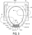
- FIG. 3
- is a cross-sectional plan view of an essential part of a toilet without a lid and a toilet seat.
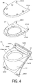
- FIG. 4
- is a perspective view of a lid, a toilet seat, and a shroud.
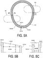
- FIG. 5A
- is a plan view of a shroud mount;
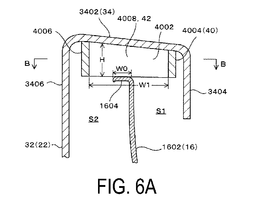
FIG. 5B is a cross-sectional view taken along BB ofFIG. 5A; and FIG. 5C is a cross-sectional view taken along CC ofFIG. 5A . - FIG. 6A
- is a cross-sectional view of a state where a flange of a shroud is placed in an upper end outer peripheral plate portion of a toilet body via a shroud mount; and
FIG. 6B is a cross-sectional view taken along BB ofFIG. 6A . - FIGS. 7A and 7B
- are explanatory views of a modified example of a shroud mount;
FIG. 7A is a cross-sectional view of a state where a flange of a shroud is placed in an upper end outer peripheral plate portion of a toilet body via the shroud mount; andFIG. 7B is a cross-sectional view taken along BB ofFIG. 7A . - FIGS. 8A and 8B
- are explanatory views of a modified example of a shroud mount;
FIG. 8A is a cross-sectional view of a state where a flange of a shroud is placed in an upper end outer peripheral plate portion of a toilet body via the shroud mount; andFIG. 8B is a cross-sectional view taken along BB ofFIG. 8A . - FIGS. 9A and 9B
- are explanatory views of a modified example of a shroud mount;
FIG. 9A is a cross-sectional view of a state where a flange of a shroud is placed in an upper end outer peripheral plate portion of a toilet body via the shroud mount; andFIG. 9B is a cross-sectional view taken along BB ofFIG. 9A . - FIGS. 10A and 10B
- are explanatory views of a modified example of a shroud mount;
FIG. 10A is a cross-sectional view of a state where a flange of a shroud is placed in an upper end outer peripheral plate portion of a toilet body via the shroud mount; andFIG. 10B is a cross-sectional view taken along BB ofFIG. 10A . - FIG. 11
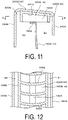
- is an explanatory view of another modified example of a shroud mount, and is a cross-sectional view of a state where a flange of a shroud is placed in an upper end outer peripheral plate portion of a toilet body via the shroud mount.
- FIG. 12
- is an explanatory view of a modified example of a partition wall, and is a view corresponding to the cross section taken along BB of
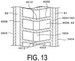
FIG. 6 . - FIG. 13
- is an explanatory view of a modified example of a partition wall, and is a view corresponding to the cross section taken along BB of
FIG. 6 . - Hereinafter, embodiments of the present invention will be described with reference to the drawings.
As illustrated inFIGS. 1 and 2 , atoilet 14 disposed in alavatory 12 of anaircraft lavatory unit 10 includes atoilet body 16, asupport portion 18, ashroud 22, atoilet seat 24, alid 26, and ashroud mount 40.
Thetoilet body 16 is made of metal and includes abowl portion 1602, and an upper end outerperipheral plate portion 1604 having an annular plate-like shape and extending outward of thebowl portion 1602 with a constant width W0 (seeFIGS. 6A and 6B ) along an upper end outer periphery of thebowl portion 1602 at an upper end of thebowl portion 1602.
A bottom portion of thebowl portion 1602 is connected to adischarge pipe 1606 that discharges waste in thebowl portion 1602 out of thebowl portion 1602 by negative pressure.
Thesupport portion 18 supports thetoilet body 16 on afloor 1204 of thelavatory 12, and in the present embodiment, supports thetoilet body 16 at a section close to arear wall 1202 of thelavatory 12. - As illustrated in
FIG. 4 , theshroud 22 is made of a synthetic resin, and includes aperipheral wall portion 32 that covers peripheries of thetoilet body 16 and thesupport portion 18, aflange 34 that is connected to an upper end of theperipheral wall portion 32 and placed in the upper end outerperipheral plate portion 1604, and anupper wall portion 36 that rises from a back end of theflange 34 positioned close to therear wall 1202, and theupper wall portion 36 is provided with a mountingportion 3602 of thetoilet seat 24 and thelid 26.
Theshroud 22 is installed in thelavatory 12 by attaching a lower end of theperipheral wall portion 32 to amounting piece 1206 on thefloor 1204 of thelavatory 12 by a bolt inserted into abolt insertion hole 3202 in each of both sides of a lower end of theperipheral wall portion 32, and by attaching theupper wall portion 36 to therear wall 1202 by a bolt inserted into thebolt insertion hole 3204 in each of both sides of theupper wall portion 36. Thetoilet seat 24 and thelid 26 include forkedportions portions portion 3602 via a support shaft 3604 (seeFIGS. 1 and 2 ), and a plurality ofcushion blocks 2402 placed in theflange 34 of theshroud 22 are attached to a lower surface of thetoilet seat 24. - As illustrated in
FIGS. 4 and6A , theflange 34 includes a mainbody plate portion 3402, an innersurface plate portion 3404, and an outersurface plate portion 3406.
The mainbody plate portion 3402 has a width larger than the width of the upper end outerperipheral plate portion 1604, and extends annularly along the extension direction (circumferential direction) of the upper end outerperipheral plate portion 1604.
The innersurface plate portion 3404 extends along the extension direction of the mainbody plate portion 3402 while projecting downward from an inner peripheral end of the mainbody plate portion 3402, and conceals the inside of the upper end outerperipheral plate portion 1604.
The outersurface plate portion 3406 extends along the extension direction of the mainbody plate portion 3402, projects downward from an outer peripheral end of the mainbody plate portion 3402, conceals the outside of the upper end outerperipheral plate portion 1604 and is connected to an upper portion of theperipheral wall portion 32. - The
shroud mount 40 is made of a synthetic resin in the present embodiment. Note that theshroud mount 40 may be made of metal or hard rubber.
Theshroud mount 40 is a separate member from theshroud 22 in the present embodiment.
As illustrated inFIGS. 5A to 5C andFIGS. 6A and 6B , theshroud mount 40 is provided at a section where theflange 34 is placed in the upper end outerperipheral plate portion 1604, and thus, theflange 34 is placed in the upper end outerperipheral plate portion 1604 via theshroud mount 40, or in other words, theshroud mount 40 is placed in the upper end outerperipheral plate portion 1604.
Theshroud mount 40 includes a plurality ofpartition walls 4002, an innerperipheral wall 4004, an outerperipheral wall 4006, and a plurality ofspace portions 4008.
Thepartition walls 4002 linearly extend in the width direction of the mainbody plate portion 3402 at sections located at an equal interval in the extension direction of the mainbody plate portion 3402.
As illustrated inFIGS. 3 and5A , an interval D between thepartition walls 4002 is such an interval that in a state where the mainbody plate portion 3402 is stepped on by afoot 90, the plurality ofpartition walls 4002 are positioned inside of a contour of thefoot 90 as viewed in a plan view (in other words, a contour of a shoe 90). - As illustrated in
FIGS. 5A to 5C , andFIGS. 6A and 6B , each one of thepartition walls 4002 has a width W1 along the width direction of the mainbody plate portion 3402 that is orthogonal to the extension direction of the mainbody plate portion 3402, a height H along the thickness direction of the mainbody plate portion 3402, and a thickness T along the extension direction of the mainbody plate portion 3402.
In the present embodiment, the interval D between thepartition walls 4002 is, for example, from 10 mm to 30 mm, and the thickness T of each one of thepartition walls 4002 is from 3 mm to 6 mm.
The width W1 of each one of thepartition walls 4002 is formed with a dimension greater than the width WO of the upper end outerperipheral plate portion 1604, allowing for thepartition walls 4002 to be reliably placed in the upper end outerperipheral plate portion 1604, and also allowing for thespace portions 4008 and air communication passages 42 described below to span a space S1 inside of the upper end outerperipheral portion 1604 in the width direction and a space S2 outside of the upper end outerperipheral portion 1604 in the width direction.
As illustrated inFIG. 6B , in the present embodiment, in a state where theflange 34 is placed in the upper end outerperipheral plate portion 1604 via theshroud mount 40, the upper end outerperipheral plate portion 1604, is positioned in an intermediate portion in the width W1 direction of thepartition walls 4002 as viewed in a plan view.
The height H of each one of thepartition walls 4002 is formed such that the outer peripheral side is higher than the inner peripheral side, and that the height gradually increases from the inner periphery to the outer periphery, allowing for thespace portions 4008 and the air communication passages 42 described below to be formed by a large cross-sectional area.
The thickness T of each one of thepartition walls 4002 is formed with such a dimension that the rigidity of thepartition walls 4002 is ensured, and in the present embodiment, the thickness of each one of thepartition walls 4002 is uniform. - As illustrated in
FIGS. 6A and 6B , the innerperipheral wall 4004 extends along the extension direction of the innersurface plate portion 3404 outside of the innersurface plate portion 3404, the outerperipheral wall 4006 extends along the extension direction of the outersurface plate portion 3406 inside of the outersurface plate portion 3406, and both ends in the extension direction of thepartition walls 4002 are connected to the innerperipheral wall 4004 and the outerperipheral wall 4006.
In other words, the strength and the rigidity of thepartition walls 4002 are ensured by the innerperipheral wall 4004 and the outerperipheral wall 4006.
Note that in the present embodiment, theshroud mount 40 is a separate member from theshroud 22, and is bonded to a lower surface of the mainbody plate portion 3402 with an adhesive. - In a state where the
shroud mount 40 is attached to the lower surface of the mainbody plate portion 3402 of theflange 34, the plurality ofspace portions 4008 are formed in theshroud mount 40 by the plurality ofpartition walls 4002 provided at intervals in the circumferential direction of the mainbody plate portion 3402. The plurality ofspace portions 4008 each having a rectangular shape in a plan view, or in other words, a linear shape in the width direction of the mainbody plate portion 3402 are opened downward between thepartition walls 4002 and extend in the width direction of the mainbody plate portion 3402.
Then, in a state where the mainbody plate portion 3402 is placed in the upper end outerperipheral plate portion 1604 via the plurality ofpartition walls 4002, the upper end outerperipheral plate portion 1604 is positioned in an intermediate portion in the longitudinal direction of thespace portions 4008 as viewed in a plan view, and a plurality of the air communication passages 42 are formed by thespace portions 4008 between the lower surface of the mainbody plate portion 3402 and the upper end outerperipheral plate portion 1604, and communicate the space S1 inside of the upper end outerperipheral plate portion 1604 in the width direction and the space S2 outside of the upper end outerperipheral plate portion 1604 in the width direction.
Thus, as illustrated inFIG. 6B , in a case where the air communication passages 42 are viewed in a plan view, the air communication passages 42 each have a linear shape elongated in the width direction of the mainbody plate portion 3402, and the upper end outerperipheral plate portion 1604 is positioned in an intermediate portion in the longitudinal direction of the air communication passages 42. - According to the present embodiment, in a state where the main
body plate portion 3402 of theflange 34 is placed in the upper end outerperipheral plate portion 1604 via the plurality ofpartition walls 4002, the plurality of air communication passages 42 are formed between the lower surface of mainbody plate portion 3402 and the upper end outerperipheral plate portion 1604 by thespace portions 4008, and communicate the space S1 inside of the upper end outerperipheral plate portion 1604 in the width direction and the space S2 outside of the upper end outerperipheral plate portion 1604 in the width direction.
In other words, a space inside of thebowl portion 1602 is communicated with the inside of thelavatory 12 via the plurality of air communication passages 42.
Thus, even when negative pressure in discharging waste acts on the inside of thetoilet body 16, the negative pressure in discharging waste does not act on the human body seating portion. In addition, as illustrated inFIGS. 3 and5A , even in a case where a user of theaircraft lavatory unit 10 put a foot on theflange 34 of theshroud 22, or even in a case where a user or a cleaning person stands up on theflange 34 of theshroud 22 while wearing theshoe 90, or in other words, even in a case where the mainbody plate portion 3402 of theflange 34 is stepped on by a foot, the plurality ofpartition walls 4002 are positioned inside of the contour of the foot (in other words, the contour of the shoe 90) as viewed in a plan view, and the load can be received directly by the plurality ofpartition walls 4002. Thus, this is advantageous in preventing breakage of theflange 34 of theshroud 22.
In addition, a cushion rubber of the related art is removed from a lower surface of theflange 34, and theshroud mount 40 is attached to the lower surface of theflange 34, and thus it is possible to also correspond to atoilet 14 used in the related art, and excellent versatility is provided.
In this case, it is more advantageous to form thepartition walls 4002 each having the same height as the dimension of a cushion block of the related art. - Note that in the present embodiment, the case where the
shroud mount 40 is a separate member from theshroud 22 and is bonded to the lower surface of the mainbody plate portion 3402 with an adhesive is described; however, theshroud mount 40 may be formed integrally with theshroud 22. This is advantageous in reducing the number of components and reducing the number of assembly steps.
As illustrated inFIGS. 7A and 7B , in a case where theshroud mount 40 is formed integrally with theshroud 22, when the rigidity of thepartition walls 4002 is increased by increasing the thickness T of each one of thepartition walls 4002, the innerperipheral wall 4004 and the outerperipheral wall 4006 can be omitted.
In addition, as illustrated inFIGS. 8A and 8B , in a case where theshroud mount 40 is formed integrally with theshroud 22, to ensure the rigidity of thepartition walls 4002, both ends in the extension direction of thepartition walls 4002 may be connected to the innersurface plate portion 3404 and the outersurface plate portion 3406, respectively. Similarly, in that case, the innerperipheral wall 4004 and the outerperipheral wall 4006 are unnecessary. - In addition, in the present embodiment, the case where the
space portions 4008 and the air communication passages 42 each have a substantially rectangular shape is described; however, regardless of whether theshroud mount 40 is separate from or formed integrally with theshroud 22, as illustrated inFIGS. 9A and 9B andFIGS. 10A and 10B , thespace portions 4008 and the air communication passages 42 may each have a hexagonal shape, an elliptical shape, or the like as viewed in a plan view, and various shapes known in the related art can be applied to the shapes of thespace portions 4008 and the air communication passages 42. The shapes of thepartition walls 4002 are appropriately determined according to the shapes of thespace portions 4008 and the air communication passages 42.
In addition, as illustrated inFIG. 11 , theshroud mount 40 may include, in addition to thepartition walls 4002, the innerperipheral wall 4004, and the outerperipheral wall 4006, abottom wall 4010 that connects thepartition walls 4002, the innerperipheral wall 4004, and the outerperipheral wall 4006. In this embodiment, thespace portions 4008 are formed to penetrate in the height direction of thepartition walls 4002; however, when thebottom wall 4010 is provided, thespace portions 4008 are each formed by thebottom wall 4010 as a recessed portion that is opened downward, and the strength and the rigidity of thepartition walls 4002 are ensured by thebottom wall 4010. - In addition, in the present embodiment, the case where the
partition walls 4002 extend linearly in the width direction of the mainbody plate portion 3402 is described; however, regardless of whether theshroud mount 40 is separate from or formed integrally with theshroud 22, as illustrated inFIG. 12 , thepartition walls 4002 curvilinearly extend, or as illustrated inFIG. 13 , thepartition walls 4002 extend being bent. Thepartition walls 4002 extend in any shape, in short, thepartition walls 4002 may have any shape as long as thepartition walls 4002 receive a load applied to theflange 34, for example, when a user puts the foot on theflange 34, and as long as thespace portions 4008 and the air communication passages 42 are formed.
Note that, as illustrated inFIG. 12 , in a case where thepartition walls 4002 each extend curvilinearly as a protrusion in the circumferential direction of thebody plate portion 3402, or, as illustrated inFIG. 13 , when thepartition walls 4002 extend being bent andbent portions 4012 of thepartition walls 4002 are positioned on the upper end outerperipheral plate portion 1604, the area of contact of thepartition walls 4002 with the upper end outerperipheral plate portion 1604 can be increased without changing the area of the air communication passages 42, and this is advantageous in increasing the durability of thepartition walls 4002, or in other words, the durability of theshroud mount 40. -
- 10
- Aircraft lavatory unit
- 12
- Lavatory
- 14
- Toilet
- 16
- Toilet body
- 1602
- Bowl portion
- 1604
- Upper end outer peripheral plate portion
- 18
- Support portion
- 22
- Shroud
- 32
- Peripheral wall portion
- 34
- Flange
- 3402
- Main body plate portion
- 3404
- Inner surface plate portion
- 3406
- Outer surface plate portion
- 36
- Upper wall portion
- 24
- Toilet seat
- 2402
- Cushion block
- 26
- Lid
- 40
- Shroud mount
- 4002
- Partition wall
- 4004
- Inner peripheral wall
- 4006
- Outer peripheral wall
- 4008
- Space portion
- 42
- Air communication passage
Claims (7)
- A toilet exterior structure of an aircraft lavatory unit, comprising:a toilet body comprising a bowl portion and an upper end outer peripheral plate portion extending along an upper end outer periphery of the bowl portion with a width at an upper end of the bowl portion;a support portion configured to support the toilet body on a floor;a shroud comprising a flange placed in a peripheral wall portion covering peripheries of the toilet body and the support portion, and placed in the upper end outer peripheral plate portion; anda toilet seat placed on the flange;the flange comprising a main body plate portion extending annularly along the upper end outer peripheral plate portion with a width larger than the width with which the upper end outer peripheral plate portion extends;
a shroud mount being placed in the upper end outer peripheral plate portion and being provided in a lower surface facing downward of the main body plate portion;
the shroud mount comprising a plurality of space portions formed by a plurality of partition walls provided at intervals in a circumferential direction of the main body plate portion, and the plurality of space portions being opened downward between the plurality of partition walls and extending in a width direction of the main body plate portion;
in a state where the main body plate portion is placed in the upper end outer peripheral plate portion via the plurality of partition walls, a plurality of air communication passages being formed by the plurality of space portions between the lower surface of the main body plate portion and the upper end outer peripheral plate portion, and communicating a space inside of the upper end outer peripheral plate portion in the width direction and a space outside of the upper end outer peripheral plate portion in the width direction; and
the intervals between the plurality of partition walls along the circumferential direction of the main body plate portion being formed with such a dimension that in a state where the main body plate portion is stepped on by a foot, the plurality of partition walls are positioned inside of a contour of the foot as viewed in a plan view. - The toilet exterior structure of an aircraft lavatory unit according to claim 1, wherein
the main body plate portion has a width orthogonal to an extension direction of the main body plate portion;
the plurality of partition walls extend in a width direction of the main body plate portion; and
as viewed in a plan view, the upper end outer peripheral plate portion is positioned in an intermediate portion in an extension direction of the plurality of partition walls. - The toilet exterior structure of an aircraft lavatory unit according to claim 1 or claim 2, wherein
the shroud mount, in addition to the plurality of partition walls, comprises an inner peripheral wall extending along an inner peripheral end of the main body plate portion at a section close to the inner peripheral end, and an outer peripheral wall extending along an extension direction of an outer peripheral end of the main body plate portion at a section close to the outer peripheral end;
the plurality of partition walls extend in the width direction of the main body plate portion, and both ends in the extension direction of the plurality of partition walls are connected to the inner peripheral wall and the outer peripheral wall; and
the shroud mount is separate from the shroud and is attached to a lower surface of the flange with an adhesive. - The toilet exterior structure of an aircraft lavatory unit according to any one of claims 1 to 3, wherein
the shroud mount is integrally formed with the shroud; and
the plurality of partition walls project from the lower surface of the main body plate portion. - The toilet exterior structure of an aircraft lavatory unit according to claim 1 to claim 2, wherein
the shroud mount is integrally formed with the shroud;
the plurality of partition walls project from the lower surface of the main body plate portion;
the flange, in addition to the main body plate portion, comprises: an inner surface plate portion extending along the extension direction of the main body plate portion while projecting downward from an inner peripheral end of the main body plate portion, and concealing an inside of the upper end outer peripheral plate portion; and an outer surface plate portion projecting downward from an outer peripheral end of the main body plate portion, extending along the extension direction of the main body plate portion, concealing an outside of the upper end outer peripheral plate portion, and connected to the peripheral wall portion; and
the plurality of partition walls extend in the width direction of the main body plate portion, and both ends in the extension direction of the plurality of partition walls are connected to the inner surface plate portion and the outer surface plate portion. - The toilet exterior structure of an aircraft lavatory unit according to any one of claims 1 to 5, wherein
the plurality of partition walls each extend curvilinearly as a protrusion in the circumferential direction of the main body plate portion. - The toilet exterior structure of an aircraft lavatory unit according to any one of claims 1 to 5, wherein
the plurality of partition walls each comprise a bent portion in an intermediate portion in the extension direction of the plurality of partition walls, and the bent portion is placed on the upper end outer peripheral plate portion.
Applications Claiming Priority (2)
| Application Number | Priority Date | Filing Date | Title |
|---|---|---|---|
| JP2017211729A JP6409941B1 (en) | 2017-11-01 | 2017-11-01 | Toilet exterior structure of aircraft restroom unit |
| PCT/JP2018/024963 WO2019087461A1 (en) | 2017-11-01 | 2018-06-29 | Toilet exterior structure of lavatory unit for aircraft |
Publications (2)
| Publication Number | Publication Date |
|---|---|
| EP3705652A1 true EP3705652A1 (en) | 2020-09-09 |
| EP3705652A4 EP3705652A4 (en) | 2021-07-28 |
Family
ID=63920483
Family Applications (1)
| Application Number | Title | Priority Date | Filing Date |
|---|---|---|---|
| EP18874875.0A Pending EP3705652A4 (en) | 2017-11-01 | 2018-06-29 | EXTERIOR TOILET STRUCTURE OF A TOILET FACILITY FOR AIRPLANES |
Country Status (4)
| Country | Link |
|---|---|
| US (1) | US11577836B2 (en) |
| EP (1) | EP3705652A4 (en) |
| JP (1) | JP6409941B1 (en) |
| WO (1) | WO2019087461A1 (en) |
Family Cites Families (17)
| Publication number | Priority date | Publication date | Assignee | Title |
|---|---|---|---|---|
| US1955579A (en) * | 1931-06-12 | 1934-04-17 | Adolph L Bernheimer | Toilet bowl |
| US2240094A (en) * | 1939-05-11 | 1941-04-29 | William H Foreman | Ventilated toilet bowl |
| US4376314A (en) * | 1981-06-12 | 1983-03-15 | Kidde, Inc. | Vehicular toilet |
| US5839127A (en) * | 1997-10-31 | 1998-11-24 | Curiel; Jesus M. | Odor extractor apparatus |
| US6226807B1 (en) * | 1999-06-04 | 2001-05-08 | Mag Aerospace Industries, Inc. | System and method for a reduced water consumption vacuum toilet |
| US20040210994A1 (en) * | 2003-04-22 | 2004-10-28 | Turkman Samsam U. | Stink-free non-overflow add-on toilet accessory |
| US7065801B1 (en) * | 2005-03-15 | 2006-06-27 | Klepfer Thomas W | Pivot mount toilet ventilation seat |
| US20060277671A1 (en) * | 2005-06-14 | 2006-12-14 | Jones Floyd O | Toilet ventilation system with replacement filtration |
| DE102007013949A1 (en) * | 2007-03-23 | 2008-09-25 | Airbus Deutschland Gmbh | Flushing arrangement and method for vacuum toilets |
| JP4953162B2 (en) * | 2007-05-15 | 2012-06-13 | Toto株式会社 | Sanitary washing device mounting structure |
| US9371135B2 (en) * | 2012-05-17 | 2016-06-21 | Mag Aerospace Industries, Llc | Toilet concepts |
| US9133611B2 (en) * | 2012-12-18 | 2015-09-15 | Yevgeniy Plugovoy | Toilet ventilation systems |
| CA2897487A1 (en) * | 2013-01-30 | 2014-08-07 | Mag Aerospace Industries, Inc. | Toilets with improved removability for passenger transport vehicles |
| EP3173333B1 (en) * | 2015-11-27 | 2020-05-13 | Airbus Operations GmbH | Dual mode toilet assembly |
| JP6229757B2 (en) * | 2016-05-27 | 2017-11-15 | 横浜ゴム株式会社 | Aircraft restroom unit |
| JP6614367B2 (en) * | 2017-11-28 | 2019-12-04 | 横浜ゴム株式会社 | Toilet seat structure of aircraft restroom unit |
| JP6493495B1 (en) * | 2017-11-28 | 2019-04-03 | 横浜ゴム株式会社 | Toilet seat structure of aircraft restroom unit |
-
2017
- 2017-11-01 JP JP2017211729A patent/JP6409941B1/en active Active
-
2018
- 2018-06-29 US US16/761,223 patent/US11577836B2/en active Active
- 2018-06-29 EP EP18874875.0A patent/EP3705652A4/en active Pending
- 2018-06-29 WO PCT/JP2018/024963 patent/WO2019087461A1/en not_active Ceased
Also Published As
| Publication number | Publication date |
|---|---|
| JP2019083835A (en) | 2019-06-06 |
| US20200354061A1 (en) | 2020-11-12 |
| EP3705652A4 (en) | 2021-07-28 |
| JP6409941B1 (en) | 2018-10-24 |
| WO2019087461A1 (en) | 2019-05-09 |
| US11577836B2 (en) | 2023-02-14 |
Similar Documents
| Publication | Publication Date | Title |
|---|---|---|
| EP3718448A1 (en) | Toilet seat structure for aircraft lavatory unit | |
| US9157223B2 (en) | Lavatory system | |
| US7201382B2 (en) | Sealing element | |
| US9072990B2 (en) | Apparatus for securing underdrain filter block | |
| US20150107011A1 (en) | Wall-Hung Toilet With Improved Load-Bearing Capacity | |
| TW200603910A (en) | Integrally formed flanged metal pipe and method of manufacturing thereof | |
| IN2012DN00800A (en) | ||
| US20220120062A1 (en) | Escutcheon | |
| US20090235449A1 (en) | Base part for stalls | |
| US11577836B2 (en) | Toilet exterior structure of aircraft lavatory unit | |
| KR102217348B1 (en) | fanel for sound insulation | |
| EP3718449A1 (en) | Toilet seat structure for aircraft lavatory unit | |
| EP2003926A1 (en) | Acoustic device for sanitary fittings | |
| KR20200000812U (en) | Floor Mat | |
| US20040191084A1 (en) | Double shell structure for air pumps | |
| KR102013723B1 (en) | Drain assembly | |
| CN205559957U (en) | Mix water valve handle convenient to accurate regulation | |
| JP2006230533A (en) | Apron attachment structure of bathtub | |
| JP7417510B2 (en) | scarf | |
| KR200465570Y1 (en) | Toilet Stool with skirt part | |
| JP7828048B1 (en) | Bathroom drainage unit | |
| JP4561502B2 (en) | Part mounting structure for molded products | |
| JP6455697B2 (en) | Bathroom wash floor | |
| CN210827731U (en) | Air pump mounting structure of intelligent closestool | |
| RU101627U1 (en) | WASHBASIN |
Legal Events
| Date | Code | Title | Description |
|---|---|---|---|
| STAA | Information on the status of an ep patent application or granted ep patent |
Free format text: STATUS: THE INTERNATIONAL PUBLICATION HAS BEEN MADE |
|
| PUAI | Public reference made under article 153(3) epc to a published international application that has entered the european phase |
Free format text: ORIGINAL CODE: 0009012 |
|
| STAA | Information on the status of an ep patent application or granted ep patent |
Free format text: STATUS: REQUEST FOR EXAMINATION WAS MADE |
|
| 17P | Request for examination filed |
Effective date: 20200424 |
|
| AK | Designated contracting states |
Kind code of ref document: A1 Designated state(s): AL AT BE BG CH CY CZ DE DK EE ES FI FR GB GR HR HU IE IS IT LI LT LU LV MC MK MT NL NO PL PT RO RS SE SI SK SM TR |
|
| AX | Request for extension of the european patent |
Extension state: BA ME |
|
| DAV | Request for validation of the european patent (deleted) | ||
| DAX | Request for extension of the european patent (deleted) | ||
| A4 | Supplementary search report drawn up and despatched |
Effective date: 20210630 |
|
| RIC1 | Information provided on ipc code assigned before grant |
Ipc: E03D 11/13 20060101AFI20210624BHEP Ipc: B64D 11/02 20060101ALI20210624BHEP Ipc: E03D 5/00 20060101ALI20210624BHEP |
|
| STAA | Information on the status of an ep patent application or granted ep patent |
Free format text: STATUS: EXAMINATION IS IN PROGRESS |
|
| 17Q | First examination report despatched |
Effective date: 20230515 |
|
| RAP3 | Party data changed (applicant data changed or rights of an application transferred) |
Owner name: THE YOKOHAMA RUBBER CO., LTD. |
|
| RAP3 | Party data changed (applicant data changed or rights of an application transferred) |
Owner name: THE YOKOHAMA RUBBER CO., LTD. |