EP3705407A1 - Smart aircraft skin impact area positioning method based on truncated reverse weighted sum - Google Patents
Smart aircraft skin impact area positioning method based on truncated reverse weighted sum Download PDFInfo
- Publication number
- EP3705407A1 EP3705407A1 EP18929038.0A EP18929038A EP3705407A1 EP 3705407 A1 EP3705407 A1 EP 3705407A1 EP 18929038 A EP18929038 A EP 18929038A EP 3705407 A1 EP3705407 A1 EP 3705407A1
- Authority
- EP
- European Patent Office
- Prior art keywords
- impact
- region
- monitoring
- digital sequence
- reverse
- Prior art date
- Legal status (The legal status is an assumption and is not a legal conclusion. Google has not performed a legal analysis and makes no representation as to the accuracy of the status listed.)
- Granted
Links
Images






Classifications
-
- G—PHYSICS
- G01—MEASURING; TESTING
- G01M—TESTING STATIC OR DYNAMIC BALANCE OF MACHINES OR STRUCTURES; TESTING OF STRUCTURES OR APPARATUS, NOT OTHERWISE PROVIDED FOR
- G01M5/00—Investigating the elasticity of structures, e.g. deflection of bridges or air-craft wings
- G01M5/0016—Investigating the elasticity of structures, e.g. deflection of bridges or air-craft wings of aircraft wings or blades
-
- B—PERFORMING OPERATIONS; TRANSPORTING
- B64—AIRCRAFT; AVIATION; COSMONAUTICS
- B64F—GROUND OR AIRCRAFT-CARRIER-DECK INSTALLATIONS SPECIALLY ADAPTED FOR USE IN CONNECTION WITH AIRCRAFT; DESIGNING, MANUFACTURING, ASSEMBLING, CLEANING, MAINTAINING OR REPAIRING AIRCRAFT, NOT OTHERWISE PROVIDED FOR; HANDLING, TRANSPORTING, TESTING OR INSPECTING AIRCRAFT COMPONENTS, NOT OTHERWISE PROVIDED FOR
- B64F5/00—Designing, manufacturing, assembling, cleaning, maintaining or repairing aircraft, not otherwise provided for; Handling, transporting, testing or inspecting aircraft components, not otherwise provided for
- B64F5/60—Testing or inspecting aircraft components or systems
-
- G—PHYSICS
- G01—MEASURING; TESTING
- G01L—MEASURING FORCE, STRESS, TORQUE, WORK, MECHANICAL POWER, MECHANICAL EFFICIENCY, OR FLUID PRESSURE
- G01L5/00—Apparatus for, or methods of, measuring force, work, mechanical power, or torque, specially adapted for specific purposes
- G01L5/0052—Apparatus for, or methods of, measuring force, work, mechanical power, or torque, specially adapted for specific purposes measuring forces due to impact
-
- B—PERFORMING OPERATIONS; TRANSPORTING
- B64—AIRCRAFT; AVIATION; COSMONAUTICS
- B64D—EQUIPMENT FOR FITTING IN OR TO AIRCRAFT; FLIGHT SUITS; PARACHUTES; ARRANGEMENT OR MOUNTING OF POWER PLANTS OR PROPULSION TRANSMISSIONS IN AIRCRAFT
- B64D45/00—Aircraft indicators or protectors not otherwise provided for
- B64D2045/0085—Devices for aircraft health monitoring, e.g. monitoring flutter or vibration
Definitions
- the present invention relates to a truncated reverse-weighted sum based impact region localization method of aircraft smart skin, belonging to the technical fields of aerospace smart structure and health monitoring.
- the basic idea of an aircraft smart skin technology is to integrate a large number of sensing/driving elements and a micro processing unit with a skin structure to form a whole, to monitor information about an environment, working state and health status of the structure through a large number of sensing elements, and to process the information via the micro processing unit to form a control stimulus, thereby changing the shape, motion, stress state and the like of the structure.
- the smart skin technology makes the skin structure have the capabilities of self-diagnosing, self-adapting, self-learning, self-repairing, etc. Therefore, the aircraft smart skin technology is an important technical guarantee to improve the flight performance, operational maneuverability, environmental sensing performance and safety maintenance performance of an advanced aircraft.
- An aircraft composite smart skin structure (hereinafter referred to as an aircraft smart skin structure) is a research and application hot spot, where structural health monitoring and diagnosis is one of the core functions thereof.
- the aircraft smart skin structure is often impacted by external objects during service, such as bird strikes, hail, gravels, and maintenance tools, which can easily cause loss of mechanical performance and reduction of load bearing capacity of the aircraft smart skin structure, threatening the safety of the structure or even the entire aircraft. Therefore, it is urgently required to carry out impact monitoring of the aircraft smart skin structure.
- an impact monitoring system needs to be able to be installed on the aircraft for on-line and continuous impact monitoring, and the requirements of low power consumption and high reliability are met to adapt to an airborne working environment.
- an airborne miniaturized impact region monitoring system is proposed and is being gradually applied.
- the system connects a piezoelectric sensor array directly to a comparator array in the system.
- Impact response signals output by the piezoelectric sensor array are converted into digital sequences through the comparator array.
- These digital sequences are collected through a programmable logic gate array, and an impact region monitoring method based on a digital sequence is solidified into the programmable logic gate array.
- the alarm of an impact region is achieved according to the collected digital sequences, thereby omitting hardware for data acquisition and signal amplification conditioning of a conventional impact monitoring system and simplifying a signal processing algorithm and an impact localization algorithm, and a complex computer system is not required.
- the system divides a region to be monitored into several impact monitoring sub-regions according to the arrangement of sensors, and an impact region monitoring method is used for locating an impact event into one sub-region. Therefore, the system has multiple features such as small size, light weight, low power consumption, convenient installation and use, large monitoring region, real-time response to impact events, and efficient storage of digital sequences and impact alarm results corresponding to impact response signals.
- a composite structure impact region localization method based on a digital sequence energy weighting factor is proposed.
- the method defines an energy weighting factor characteristic parameter of a digital sequence, and is used for characterizing the degree of impact influence on each sensor within the entire impact monitoring range, thereby calculating the degree of impact influence on each sub-region within the monitoring range, and finally determining a sub-region which is most affected as an impact occurring sub-region.
- the present invention solves the problems of adjacent node localization conflicts and intermediate region localization blind regions occurring in the existing multi-node large-scale network monitoring.
- the composite structure impact region localization method based on a digital sequence energy weighting factor needs to be solidified into the programmable logic gate array of the miniaturized impact region monitoring system through embedded language programming.
- the method needs to sort and divide the features of a digital sequence, and the algorithm is more complex, which increases the difficulty of embedded programming implementation and improves the hardware requirements of an impact region monitoring system, thereby resulting in increased power consumption and reduced reliability.
- the impact region localization accuracy of the method needs to be improved.
- the present invention proposes a truncated reverse-weighted sum based impact region localization method of aircraft smart skin.
- the method can effectively avoid the use of sorting and division in an algorithm, and can improve the localization accuracy of an impact region and improve the reliability of an impact region monitoring system while reducing the processor complexity of the impact region monitoring system and the power consumption required during the calculation of the position of the impact region, which is conducive to the implementation of the airborne applications of the impact region monitoring system.
- the method can also effectively solve the problem of localization conflicts existing in network monitoring of multiple impact region monitoring systems and the problem of difficulty in accurately locating an intermediate region.
- a truncated reverse-weighted sum based impact region localization method of aircraft smart skin includes: firstly, truncating each digital sequence of each piezoelectric sensor as a characteristic digital sequence according to a chronological order, and calculating a reverse-weighted value of the characteristic digital sequence; then, calculating, by a monitoring center according to the piezoelectric sensors constituting impact monitoring sub-regions, a reverse-weighted sum of each impact monitoring sub-region; and finally, identifying the impact monitoring sub-region with the maximum reverse-weighted sum as a region where an impact occurs.
- each piezoelectric sensor in each group of piezoelectric sensor arrays is connected to a data acquisition channel of an impact region monitoring system, all the impact region monitoring systems are connected to one monitoring center, and a total of P piezoelectric sensors are disposed in the entire monitoring region.
- the impact monitoring region is divided into sub-regions by using the position of each piezoelectric sensor disposed on the surface of the aircraft smart skin structure as a vertex of an impact monitoring sub-region.
- Each impact monitoring sub-region is composed of R vertexes, R being a natural number greater than 2.
- each piezoelectric sensor in a piezoelectric sensor array connected thereto, the length of each digital sequence of each piezoelectric sensor is set to be K, and each digital sequence is represented as DS( i , W i ), where i is a serial number of a point in each digital sequence, i is a natural number greater than 0 and less than or equal to K, W i is a value of an i th point in each digital sequence, and W i has a value of 0 or 1.
- the method includes the following steps:
- Piezoelectric sensors and impact region monitoring systems are arranged on a composite wing smart skin structure of an unmanned aerial vehicle, and impact monitoring is performed on a wing to illustrate a specific implementation process of the method of the present invention.
- 30 piezoelectric sensors are arranged on an inner surface of the composite wing smart skin structure of the unmanned aerial vehicle, which are recorded as piezoelectric sensors 1 to 30, where the piezoelectric sensors 1 to 15 are connected to an impact region monitoring system 1.
- the piezoelectric sensors 1 to 15 constitute eight impact monitoring sub-regions, which are recorded as a sub-region 1 to a sub-region 8.
- the piezoelectric sensors 16 to 30 are connected to an impact region monitoring system 2, and also constitute eight impact monitoring sub-regions, which are recorded as a sub-region 9 to a sub-region 16.
- four intermediate sub-regions exist between monitoring regions of the impact region monitoring system 1 and the impact region monitoring system 2, which are recorded as a sub-region 17 to a sub-region 20.
- Each impact monitoring sub-region is surrounded by four piezoelectric sensors. Both the impact region monitoring systems 1 and 2 are connected to one monitoring center.
- P piezoelectric sensors and M impact region monitoring systems are arranged on a composite wing smart skin structure of an unmanned aerial vehicle, and totally constitute Q impact monitoring sub-regions.
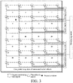
- An impact is applied to the impact monitoring sub-region 2 at a position as shown in Fig. 3 .
- the piezoelectric sensors 1 to 15 generate impact response signals
- the impact region monitoring system 1 converts the response signals of the 15 piezoelectric sensors into 15 digital sequences
- the obtained digital sequences are as shown in Fig. 4 .
- the working flow of the entire monitoring system is as follows:
- P piezoelectric sensors and M impact region monitoring systems are arranged on a composite wing smart skin structure of an unmanned aerial vehicle, and totally constitute Q impact monitoring sub-regions.
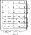
- An impact is applied to the impact monitoring sub-region 17 at a position as shown in Fig. 8 .
- the piezoelectric sensors 1 to 30 generate impact response signals
- the impact region monitoring system 1 converts the response signals of the piezoelectric sensors 1 to 15 into digital sequences
- the impact region monitoring system 2 converts the response signals of the piezoelectric sensors 16 to 30 into digital sequences, there are a total of 30 digital sequences, and each of the acquired digital sequences has a length of 500 points.
- the obtained digital sequences are as shown in Fig. 9 .
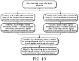
- a flowchart of an impact region localization algorithm shown in Fig. 10 the working flow of the entire monitoring system is as follows:
- the present invention defines a reverse-weighted value to indicate the degree of impact influence on each piezoelectric sensor within the monitoring range, and then uniformly evaluates the degrees of impact influences on all sub-regions and finally locates an impact occurring sub-region, and the problem of localization conflicts in multiple adjacent node monitoring regions and the problem of localization of an intermediate sub-region can be solved. Moreover, since only addition, subtraction and multiplication are needed, the complexity of an algorithm is reduced, the computation burden of the algorithm is reduced, the hardware requirements of an impact region monitoring system can be reduced, the reliability of the impact region monitoring system is improved, and it is more favorable for implementing an airborne impact region monitoring system.
Landscapes
- Engineering & Computer Science (AREA)
- Aviation & Aerospace Engineering (AREA)
- Physics & Mathematics (AREA)
- General Physics & Mathematics (AREA)
- Manufacturing & Machinery (AREA)
- Transportation (AREA)
- Force Measurement Appropriate To Specific Purposes (AREA)
- Geophysics And Detection Of Objects (AREA)
Abstract
Description
- The present invention relates to a truncated reverse-weighted sum based impact region localization method of aircraft smart skin, belonging to the technical fields of aerospace smart structure and health monitoring.
- The basic idea of an aircraft smart skin technology is to integrate a large number of sensing/driving elements and a micro processing unit with a skin structure to form a whole, to monitor information about an environment, working state and health status of the structure through a large number of sensing elements, and to process the information via the micro processing unit to form a control stimulus, thereby changing the shape, motion, stress state and the like of the structure. The smart skin technology makes the skin structure have the capabilities of self-diagnosing, self-adapting, self-learning, self-repairing, etc. Therefore, the aircraft smart skin technology is an important technical guarantee to improve the flight performance, operational maneuverability, environmental sensing performance and safety maintenance performance of an advanced aircraft.
- In recent years, composites have been widely used in aircraft structures because of the high specific stiffness, strong resistance to fatigue and corrosion, and flexible design. An aircraft composite smart skin structure (hereinafter referred to as an aircraft smart skin structure) is a research and application hot spot, where structural health monitoring and diagnosis is one of the core functions thereof. The aircraft smart skin structure is often impacted by external objects during service, such as bird strikes, hail, gravels, and maintenance tools, which can easily cause loss of mechanical performance and reduction of load bearing capacity of the aircraft smart skin structure, threatening the safety of the structure or even the entire aircraft. Therefore, it is urgently required to carry out impact monitoring of the aircraft smart skin structure. In addition, since the impact on an aircraft structure is a random transient event that needs to be monitored at the moment of an impact, an impact monitoring system needs to be able to be installed on the aircraft for on-line and continuous impact monitoring, and the requirements of low power consumption and high reliability are met to adapt to an airborne working environment.
- At present, most impact localization methods are designed to achieve accurate localization of impacts, but these methods require pre-acquisition of impact response signals of piezoelectric sensors or other acoustic emission sensors. Therefore, signal amplification circuits, time domain signal sampling circuits and computer systems for processing complex localization algorithms are required in the hardware of the impact monitoring system, and complex signal processing algorithms and impact localization algorithms need to be included in software architecture. These systems are bulky and power consuming, thereby limiting integration applications on the aircraft.
- In response to the foregoing problems, an airborne miniaturized impact region monitoring system is proposed and is being gradually applied. The system connects a piezoelectric sensor array directly to a comparator array in the system. Impact response signals output by the piezoelectric sensor array are converted into digital sequences through the comparator array. These digital sequences are collected through a programmable logic gate array, and an impact region monitoring method based on a digital sequence is solidified into the programmable logic gate array. The alarm of an impact region is achieved according to the collected digital sequences, thereby omitting hardware for data acquisition and signal amplification conditioning of a conventional impact monitoring system and simplifying a signal processing algorithm and an impact localization algorithm, and a complex computer system is not required. Moreover, the system divides a region to be monitored into several impact monitoring sub-regions according to the arrangement of sensors, and an impact region monitoring method is used for locating an impact event into one sub-region. Therefore, the system has multiple features such as small size, light weight, low power consumption, convenient installation and use, large monitoring region, real-time response to impact events, and efficient storage of digital sequences and impact alarm results corresponding to impact response signals.
- However, a real aircraft often needs to perform impact monitoring on multiple large-region aircraft smart skin structures, such as a wing, a fuselage, a vertical tail and other smart skin structures. Therefore, it is usually necessary to use multiple impact monitoring nodes for network monitoring. When large-scale network impact monitoring is performed on the same structure by multiple monitoring nodes, there are two problems as follows:
- (1) When monitoring regions of multiple monitoring nodes are adjacent, an impact occurring in one region may trigger other nodes to perform impact monitoring. If each node separately locates the impact, localization conflicts may be caused. Therefore, in actual applications, an impact localization algorithm is required to eliminate such conflicts, and impact records of multiple nodes are combined to determine a correct impact occurring region.
- (2) There are often intermediate regions between adjacent monitoring regions. These intermediate regions do not belong to the monitoring range of any one node, but impact monitoring is also required. A localization algorithm working in a single node can only perform impact monitoring and localization on a region within the monitoring range of the node, and these intermediate regions cannot be located. Therefore, a new impact localization algorithm is needed to identify and locate impacts occurring on these intermediate regions.
- In order to solve the foregoing problems, a composite structure impact region localization method based on a digital sequence energy weighting factor is proposed. The method defines an energy weighting factor characteristic parameter of a digital sequence, and is used for characterizing the degree of impact influence on each sensor within the entire impact monitoring range, thereby calculating the degree of impact influence on each sub-region within the monitoring range, and finally determining a sub-region which is most affected as an impact occurring sub-region. The present invention solves the problems of adjacent node localization conflicts and intermediate region localization blind regions occurring in the existing multi-node large-scale network monitoring.
- Then, in order to achieve online and continuous impact monitoring, the composite structure impact region localization method based on a digital sequence energy weighting factor needs to be solidified into the programmable logic gate array of the miniaturized impact region monitoring system through embedded language programming. However, the method needs to sort and divide the features of a digital sequence, and the algorithm is more complex, which increases the difficulty of embedded programming implementation and improves the hardware requirements of an impact region monitoring system, thereby resulting in increased power consumption and reduced reliability. In addition, the impact region localization accuracy of the method needs to be improved. Therefore, it is necessary to propose a simple and reliable and more accurate impact region localization algorithm, which can reduce the power consumption of an impact region monitoring system, improve the system reliability, make the impact region monitoring system airborne, and also solve the foregoing problem of large-scale network impact monitoring.
- In order to solve the foregoing problems, the present invention proposes a truncated reverse-weighted sum based impact region localization method of aircraft smart skin. The method can effectively avoid the use of sorting and division in an algorithm, and can improve the localization accuracy of an impact region and improve the reliability of an impact region monitoring system while reducing the processor complexity of the impact region monitoring system and the power consumption required during the calculation of the position of the impact region, which is conducive to the implementation of the airborne applications of the impact region monitoring system. Moreover, the method can also effectively solve the problem of localization conflicts existing in network monitoring of multiple impact region monitoring systems and the problem of difficulty in accurately locating an intermediate region.
- The present invention adopts the following technical solutions to solve the technical problem:
- A truncated reverse-weighted sum based impact region localization method of aircraft smart skin is provided. The impact region localization method includes: firstly, truncating each digital sequence of each piezoelectric sensor as a characteristic digital sequence according to a chronological order, and calculating a reverse-weighted value of the characteristic digital sequence; then, calculating, by a monitoring center according to the piezoelectric sensors constituting impact monitoring sub-regions, a reverse-weighted sum of each impact monitoring sub-region; and finally, identifying the impact monitoring sub-region with the maximum reverse-weighted sum as a region where an impact occurs.
- M groups of piezoelectric sensor arrays are disposed in an impact monitoring region on the surface of an aircraft smart skin structure used in the impact region localization method, each piezoelectric sensor in each group of piezoelectric sensor arrays is connected to a data acquisition channel of an impact region monitoring system, all the impact region monitoring systems are connected to one monitoring center, and a total of P piezoelectric sensors are disposed in the entire monitoring region. The impact monitoring region is divided into sub-regions by using the position of each piezoelectric sensor disposed on the surface of the aircraft smart skin structure as a vertex of an impact monitoring sub-region. Each impact monitoring sub-region is composed of R vertexes, R being a natural number greater than 2. It is supposed that Q impact monitoring sub-regions are obtained by division, Q being a natural number greater than 0. When an impact occurs in the structure, all the impact region monitoring systems obtain digital sequences corresponding to each piezoelectric sensor in a piezoelectric sensor array connected thereto, the length of each digital sequence of each piezoelectric sensor is set to be K, and each digital sequence is represented as DS(i, Wi ), where i is a serial number of a point in each digital sequence, i is a natural number greater than 0 and less than or equal to K, Wi is a value of an i th point in each digital sequence, and Wi has a value of 0 or 1.
- The method includes the following steps:
- step 1: truncating a digital sequence:
setting a truncating length as N that is a natural number greater than 0 and less than K, truncating a digital sequence of each piezoelectric sensor according to a chronological order, and truncating a digital sequence having a length of N as a characteristic digital sequence corresponding to the piezoelectric sensor from front to back, which is represented as TDS(j, Wj ), where j is a serial number of a point in the characteristic digital sequence, j is a natural number greater than 0 and less than or equal to N, Wj is a value of a j th point in the characteristic digital sequence, and Wj has a value of 0 or 1; - step 2: calculating a reverse-weighted value of a characteristic digital sequence:
the method for calculating a reverse-weighted value RWr of a characteristic digital sequence being as shown in Formula (1), RWr being a reverse-weighted value of a characteristic digital sequence corresponding to an r th piezoelectric sensor in the entire monitoring region, and r being greater than 0 and less than or equal to P, where a specific calculation method is: multiplying a value of a first point in the characteristic digital sequence by N, multiplying a value of a second point in the characteristic digital sequence by N-1, multiplying a value of a third point in the characteristic digital sequence by N-2, and so on, multiplying a value of an N th point in the characteristic digital sequence by 1, and adding the N values;
- step 3: calculating a reverse-weighted sum of an impact monitoring sub-region:
calculating a sum RWAq of reverse-weighted values of the piezoelectric sensors at all vertexes of each impact monitoring sub-region in the impact monitoring region by using a method as shown in Formula (2):
- step 4: identifying an impact monitoring sub-region where an impact occurs:
identifying the impact monitoring sub-region corresponding to the maximum reverse-weighted sum of all the impact monitoring sub-regions as a region where an impact occurs. - The present invention has the following beneficial effects:
- 1. The present invention provides a multi-system joint localization method for network monitoring of multiple impact region monitoring systems, which solves the problem of localization conflicts when monitoring regions of the plurality of impact region monitoring systems are adjacent, and can accurately perform impact localization on an intermediate region.
- 2. The impact region localization method proposed by the present invention only needs to perform addition, subtraction and multiplication operations, thereby avoiding complex operations such as division and sorting, reducing the complexity of an algorithm, reducing the computation burden of the algorithm, reducing the hardware requirements of the impact region monitoring systems, and implementing the algorithm by using embedded programming. The reliability of the impact region monitoring systems is improved, and it is more conducive to airborne implementation.
- 3. Compared with a composite structure impact region localization method based on a digital sequence energy weighting factor, the present invention improves the accuracy of impact region localization, and can improve the smartness of an aircraft smart skin structure and reduce the maintenance cost thereof.
-
-
Fig. 1 is a flowchart showing steps of a truncated reverse-weighted sum based impact region localization method of aircraft smart skin. -
Fig. 2 is a schematic diagram showing the arrangement of a piezoelectric sensor and an impact region monitoring system of a composite wing smart skin structure of an unmanned aerial vehicle. -
Fig. 3 is a schematic diagram of an impact application position inEmbodiment 1. -
Fig. 4 is a diagram of impact digital sequences of 15 piezoelectric sensors inEmbodiment 1. -
Fig. 5 is a flowchart showing steps of an impact region localization method inEmbodiment 1. -
Fig. 6 is a distribution diagram of reverse-weighted values of 15 piezoelectric sensors inEmbodiment 1. -
Fig. 7 is a distribution diagram of reverse-weighted sums of 8 impact monitoring sub-regions inEmbodiment 1. -
Fig. 8 is a schematic diagram of an impact application position inEmbodiment 2. -
Fig. 9 is a diagram of impact digital sequences of 30 piezoelectric sensors inEmbodiment 2. -
Fig. 10 is a flowchart showing steps of an impact region localization method inEmbodiment 2. -
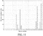
Fig. 11 is a distribution diagram of reverse-weighted values of 30 piezoelectric sensors inEmbodiment 2. -
Fig. 12 is a distribution diagram of reverse-weighted sums of 20 impact monitoring sub-regions inEmbodiment 2. - In order to better explain the technical solutions of the present invention, the present invention will be described in detail below with reference to the accompanying drawings and two embodiments. The steps of a truncated reverse-weighted sum based impact region localization method of aircraft smart skin are as shown in
Fig. 1 . - Piezoelectric sensors and impact region monitoring systems are arranged on a composite wing smart skin structure of an unmanned aerial vehicle, and impact monitoring is performed on a wing to illustrate a specific implementation process of the method of the present invention. As shown in
Fig. 2 , 30 piezoelectric sensors are arranged on an inner surface of the composite wing smart skin structure of the unmanned aerial vehicle, which are recorded aspiezoelectric sensors 1 to 30, where thepiezoelectric sensors 1 to 15 are connected to an impactregion monitoring system 1. As shown in the figure, thepiezoelectric sensors 1 to 15 constitute eight impact monitoring sub-regions, which are recorded as asub-region 1 to asub-region 8. Thepiezoelectric sensors 16 to 30 are connected to an impactregion monitoring system 2, and also constitute eight impact monitoring sub-regions, which are recorded as asub-region 9 to asub-region 16. In addition, four intermediate sub-regions exist between monitoring regions of the impactregion monitoring system 1 and the impactregion monitoring system 2, which are recorded as asub-region 17 to asub-region 20. Each impact monitoring sub-region is surrounded by four piezoelectric sensors. Both the impactregion monitoring systems - In the present embodiment, P piezoelectric sensors and M impact region monitoring systems are arranged on a composite wing smart skin structure of an unmanned aerial vehicle, and totally constitute Q impact monitoring sub-regions. Each impact monitoring sub-region is composed of R vertexes, where P=15, M=1, Q=8, and R=4. An impact is applied to the
impact monitoring sub-region 2 at a position as shown inFig. 3 . Thepiezoelectric sensors 1 to 15 generate impact response signals, the impactregion monitoring system 1 converts the response signals of the 15 piezoelectric sensors into 15 digital sequences, and each of the acquired digital sequences has a length of K, where K=500. The obtained digital sequences are as shown inFig. 4 . According to a flowchart of an impact region localization algorithm shown inFig. 5 , the working flow of the entire monitoring system is as follows: - 1: Set a value N, truncate a digital sequence of each piezoelectric sensor obtained by an impact
region monitoring system 1 according to a chronological order, and truncate a digital sequence having a length of N as a characteristic digital sequence corresponding to the piezoelectric sensor from front to back, where N=50 in the present embodiment, that is, first 50 points of each digital sequence are truncated as the characteristic digital sequence of the piezoelectric sensor. - 2: Calculate, by the impact
region monitoring system 1, reverse-weighted values of characteristic digital sequences ofpiezoelectric sensors 1 to 15 according to the obtained characteristic digital sequences through Formula (1), results being shown inFig. 6 . - 3: Calculate a sum of reverse-weighted values of four piezoelectric sensors at vertexes of each impact monitoring sub-region in eight impact monitoring sub-regions within an impact monitoring region, the distribution condition of the reverse-weighted sum of each impact monitoring sub-region being shown in
Fig. 7 . - 4: Identify an impact monitoring sub-region where an impact occurs. It can be seen from
Fig. 7 that an impact monitoring sub-region corresponding to the maximum reverse-weighted sum of all the impact monitoring sub-regions is thesub-region 2, and the impact monitoring sub-region is identified as an impact monitoring sub-region where an impact occurs, which is consistent with an impact monitoring sub-region where the impact actually occurs. - In the present embodiment, P piezoelectric sensors and M impact region monitoring systems are arranged on a composite wing smart skin structure of an unmanned aerial vehicle, and totally constitute Q impact monitoring sub-regions. Each impact monitoring sub-region is composed of R vertexes, where P=30, M=2, Q=20, and R=4. An impact is applied to the
impact monitoring sub-region 17 at a position as shown inFig. 8 . Thepiezoelectric sensors 1 to 30 generate impact response signals, the impactregion monitoring system 1 converts the response signals of thepiezoelectric sensors 1 to 15 into digital sequences, the impactregion monitoring system 2 converts the response signals of thepiezoelectric sensors 16 to 30 into digital sequences, there are a total of 30 digital sequences, and each of the acquired digital sequences has a length of 500 points. The obtained digital sequences are as shown inFig. 9 . According to a flowchart of an impact region localization algorithm shown inFig. 10 , the working flow of the entire monitoring system is as follows: - 1: Set a value N, truncate a digital sequence of each piezoelectric sensor obtained by impact
region monitoring systems - 2: Respectively calculate, by the impact
region monitoring systems piezoelectric sensors 1 to 15 and 16 to 30 according to the obtained characteristic digital sequences through Formula (1), results being shown inFig. 11 . - 3: Calculate, by a monitoring center, a sum of reverse-weighted values of four piezoelectric sensors at vertexes of each impact monitoring sub-region in 20 impact monitoring sub-regions within an impact monitoring region, the distribution condition of the reverse-weighted sum of each impact monitoring sub-region being shown in
Fig. 12 . - 4: Identify an impact monitoring sub-region where an impact occurs. It can be seen from
Fig. 12 that an impact monitoring sub-region corresponding to the maximum reverse-weighted sum of all the impact monitoring sub-regions is thesub-region 17, and therefore the monitoring center identifies the impact monitoring sub-region as an impact monitoring sub-region where an impact occurs, which is consistent with an impact monitoring sub-region where the impact actually occurs. - The present invention defines a reverse-weighted value to indicate the degree of impact influence on each piezoelectric sensor within the monitoring range, and then uniformly evaluates the degrees of impact influences on all sub-regions and finally locates an impact occurring sub-region, and the problem of localization conflicts in multiple adjacent node monitoring regions and the problem of localization of an intermediate sub-region can be solved. Moreover, since only addition, subtraction and multiplication are needed, the complexity of an algorithm is reduced, the computation burden of the algorithm is reduced, the hardware requirements of an impact region monitoring system can be reduced, the reliability of the impact region monitoring system is improved, and it is more favorable for implementing an airborne impact region monitoring system.
Claims (2)
- A truncated reverse-weighted sum based impact region localization method of aircraft smart skin, the impact region localization method comprising: firstly, truncating each digital sequence of each piezoelectric sensor as a characteristic digital sequence according to a chronological order, and calculating a reverse-weighted value of the characteristic digital sequence; then, calculating, by a monitoring center according to piezoelectric sensors constituting impact monitoring sub-regions, a reverse-weighted sum of each impact monitoring sub-region; and finally, identifying the impact monitoring sub-region with the maximum reverse-weighted sum as a region where an impact occurs.
- The truncated reverse-weighted sum based impact region localization method of aircraft smart skin according to claim 1, wherein M groups of piezoelectric sensor arrays are disposed in an impact monitoring region on the surface of an aircraft smart skin structure used in the impact region localization method, each piezoelectric sensor in each group of piezoelectric sensor arrays is connected to a data acquisition channel of an impact region monitoring system, all the impact region monitoring systems are connected to one monitoring center, and a total of P piezoelectric sensors are disposed in the entire monitoring region; the impact monitoring region is divided into sub-regions by using the position of each piezoelectric sensor disposed on the surface of the aircraft smart skin structure as a vertex of an impact monitoring sub-region, each impact monitoring sub-region being composed of R vertexes, and R being a natural number greater than 2; it is supposed that Q impact monitoring sub-regions are obtained by division, Q being a natural number greater than 0; when an impact occurs in the aircraft smart skin structure, all the impact region monitoring systems obtain a digital sequence corresponding to each piezoelectric sensor in a piezoelectric sensor array connected thereto, the length of the digital sequence of each piezoelectric sensor is set to be K, and the digital sequence is represented as DS(i, Wi ), wherein i is a serial number of a point in the digital sequence, i is a natural number greater than 0 and less than or equal to K, Wi is a value of an i th point in the digital sequence, and Wi has a value of 0 or 1;
the method comprises the following steps:step 1: truncating a digital sequence:
setting a truncating length as N that is a natural number greater than 0 and less than K, truncating a digital sequence of each piezoelectric sensor according to a chronological order, and truncating a digital sequence having a length of N as a characteristic digital sequence corresponding to the piezoelectric sensor from front to back, which is represented as TDS(j, Wj ), wherein j is a serial number of a point in the characteristic digital sequence, j is a natural number greater than 0 and less than or equal to N, Wj is a value of a j th point in the characteristic digital sequence, and Wj has a value of 0 or 1;step 2: calculating a reverse-weighted value of a characteristic digital sequence:
the method for calculating a reverse-weighted value RWr of a characteristic digital sequence being as shown in Formula (1), RWr being a reverse-weighted value of a characteristic digital sequence corresponding to an r th piezoelectric sensor in the entire monitoring region, and r being greater than 0 and less than or equal to P, wherein a specific calculation method is: multiplying a value of a first point in the characteristic digital sequence by N, multiplying a value of a second point in the characteristic digital sequence by N-1, multiplying a value of a third point in the characteristic digital sequence by N-2, and so on, multiplying a value of an N th point in the characteristic digital sequence by 1, and adding the N values; step 3: calculating a reverse-weighted sum of an impact monitoring sub-region:
calculating a sum RWAq of reverse-weighted values of the piezoelectric sensors at all vertexes of each impact monitoring sub-region in the impact monitoring region by using a method as shown in Formula (2): step 4: identifying an impact monitoring sub-region where an impact occurs: identifying the impact monitoring sub-region corresponding to the maximum reverse-weighted sum of all the impact monitoring sub-regions as a region where an impact occurs.
Applications Claiming Priority (2)
| Application Number | Priority Date | Filing Date | Title |
|---|---|---|---|
| CN201810907588.7A CN109159913B (en) | 2018-08-10 | 2018-08-10 | Localization method of aircraft intelligent skin impact area based on truncated reverse weighted sum |
| PCT/CN2018/122670 WO2020029512A1 (en) | 2018-08-10 | 2018-12-21 | Smart aircraft skin impact area positioning method based on truncated reverse weighted sum |
Publications (4)
| Publication Number | Publication Date |
|---|---|
| EP3705407A1 true EP3705407A1 (en) | 2020-09-09 |
| EP3705407A4 EP3705407A4 (en) | 2021-09-01 |
| EP3705407B1 EP3705407B1 (en) | 2022-06-15 |
| EP3705407B8 EP3705407B8 (en) | 2022-08-03 |
Family
ID=64895447
Family Applications (1)
| Application Number | Title | Priority Date | Filing Date |
|---|---|---|---|
| EP18929038.0A Active EP3705407B8 (en) | 2018-08-10 | 2018-12-21 | Truncated reverse-weighted sum based impact region localization method of aircraft smart skin |
Country Status (3)
| Country | Link |
|---|---|
| EP (1) | EP3705407B8 (en) |
| CN (1) | CN109159913B (en) |
| WO (1) | WO2020029512A1 (en) |
Families Citing this family (1)
| Publication number | Priority date | Publication date | Assignee | Title |
|---|---|---|---|---|
| CN119986035B (en) * | 2025-03-11 | 2025-10-10 | 西北工业大学 | Flexible pressure sensor array for unmanned aerial vehicle airspeed measurement and preparation method thereof |
Family Cites Families (8)
| Publication number | Priority date | Publication date | Assignee | Title |
|---|---|---|---|---|
| US6715992B2 (en) * | 2001-04-04 | 2004-04-06 | R & M Technology, Llc | Helicopter blade and method of manufacture |
| CN1868807A (en) * | 2005-05-23 | 2006-11-29 | 北京航空航天大学 | Layer spreading design calculating method of composite material according to rigidity requirement |
| US8066252B2 (en) * | 2007-01-12 | 2011-11-29 | The Boeing Company | Methods and systems for lifting a vehicle |
| CN201151484Y (en) * | 2007-12-28 | 2008-11-19 | 同济大学 | Composite stressed-skin construction |
| FR2961491B1 (en) * | 2010-06-22 | 2012-07-13 | Airbus Operations Sas | DEVICE FOR MAINTAINING AN INSULATING MATTRESS AND FASTENING SYSTEMS FOR MOUNTING IN AN AIRCRAFT |
| CN104215528B (en) * | 2014-09-09 | 2016-08-17 | 南京航空航天大学 | Composite structure shock zone localization method based on energy weighter factor |
| CN108146615A (en) * | 2017-12-07 | 2018-06-12 | 南京航空航天大学 | Aircraft electromechanical integration large area flexible Impact monitoring smart skins system |
| CN108169037B (en) * | 2017-12-15 | 2019-03-29 | 南京航空航天大学 | Continuous heterogeneous large-area shock monitoring network and shock area location method |
-
2018
- 2018-08-10 CN CN201810907588.7A patent/CN109159913B/en active Active
- 2018-12-21 WO PCT/CN2018/122670 patent/WO2020029512A1/en not_active Ceased
- 2018-12-21 EP EP18929038.0A patent/EP3705407B8/en active Active
Also Published As
| Publication number | Publication date |
|---|---|
| CN109159913A (en) | 2019-01-08 |
| EP3705407B8 (en) | 2022-08-03 |
| WO2020029512A1 (en) | 2020-02-13 |
| CN109159913B (en) | 2019-08-30 |
| EP3705407A4 (en) | 2021-09-01 |
| EP3705407B1 (en) | 2022-06-15 |
Similar Documents
| Publication | Publication Date | Title |
|---|---|---|
| Liu et al. | An audio-based fault diagnosis method for quadrotors using convolutional neural network and transfer learning | |
| CA2807984C (en) | Method and system for monitoring a structure | |
| Son et al. | Deep learning-based anomaly detection to classify inaccurate data and damaged condition of a cable-stayed bridge | |
| CN112347571B (en) | Rolling bearing residual life prediction method considering model and data uncertainty | |
| CN117874905B (en) | Method, system, equipment and storage medium for predicting damage of airplane windshield | |
| CN116560341B (en) | Industrial robot fault diagnosis model and fault diagnosis method | |
| CN103674538A (en) | Multi-fault mode identification method and device of swashplate of helicopter | |
| CN117890099A (en) | An intelligent diagnosis method for gearbox faults based on multi-sensor fusion | |
| CN120592817A (en) | UAV patrol management method and system based on new energy stations | |
| EP3705407B1 (en) | Smart aircraft skin impact area positioning method based on truncated reverse weighted sum | |
| CN116937819B (en) | Remote power distribution cabinet monitoring system with learning function | |
| CN108388229B (en) | Health degree-based four-rotor random hybrid system health assessment method | |
| Qiu et al. | Civil engineering structural damage identification by integrating benchmark numerical model and PCNN network | |
| CN120805086B (en) | Engine flight thrust estimation method integrating countermeasure self-coding and sparse attention | |
| CN115268414A (en) | Fault prediction method and system for aircraft flight control system | |
| CN117189720B (en) | Fault diagnosis method for hydraulic system of aircraft | |
| CN119596301A (en) | Moving target monitoring method based on unmanned aerial vehicle | |
| Arts | A Novel Approach to Flight Phase Identification using Machine Learning | |
| CN115423810A (en) | Blade icing form analysis method for wind generating set | |
| Zhou et al. | Research on Anomaly Detection Method for the Executive Motor of Six-Rotor Unmanned Aerial Vehicle | |
| CN120257856B (en) | Flight safety risk assessment modeling and analysis method | |
| Meng et al. | Research on Typical Fault Diagnosis of Fixed-Wing Unmanned Aerial Vehicles Based on CNN-LSTM-Attention Model | |
| Liu et al. | Aero-Engine Starting Performance Parameters Prediction Based on AdaBoost. Rt_elm Algorithm | |
| CN120086695B (en) | A ship power data processing system, method and medium | |
| Yunlong et al. | Diagnosis of UAVs Faults Under Small Sample Conditions |
Legal Events
| Date | Code | Title | Description |
|---|---|---|---|
| STAA | Information on the status of an ep patent application or granted ep patent |
Free format text: STATUS: THE INTERNATIONAL PUBLICATION HAS BEEN MADE |
|
| PUAI | Public reference made under article 153(3) epc to a published international application that has entered the european phase |
Free format text: ORIGINAL CODE: 0009012 |
|
| STAA | Information on the status of an ep patent application or granted ep patent |
Free format text: STATUS: REQUEST FOR EXAMINATION WAS MADE |
|
| 17P | Request for examination filed |
Effective date: 20200604 |
|
| AK | Designated contracting states |
Kind code of ref document: A1 Designated state(s): AL AT BE BG CH CY CZ DE DK EE ES FI FR GB GR HR HU IE IS IT LI LT LU LV MC MK MT NL NO PL PT RO RS SE SI SK SM TR |
|
| AX | Request for extension of the european patent |
Extension state: BA ME |
|
| A4 | Supplementary search report drawn up and despatched |
Effective date: 20210729 |
|
| RIC1 | Information provided on ipc code assigned before grant |
Ipc: B64F 5/60 20170101AFI20210723BHEP Ipc: G01L 5/00 20060101ALI20210723BHEP Ipc: G01M 5/00 20060101ALI20210723BHEP Ipc: G01N 3/30 20060101ALI20210723BHEP |
|
| DAV | Request for validation of the european patent (deleted) | ||
| DAX | Request for extension of the european patent (deleted) | ||
| GRAP | Despatch of communication of intention to grant a patent |
Free format text: ORIGINAL CODE: EPIDOSNIGR1 |
|
| STAA | Information on the status of an ep patent application or granted ep patent |
Free format text: STATUS: GRANT OF PATENT IS INTENDED |
|
| INTG | Intention to grant announced |
Effective date: 20220311 |
|
| GRAS | Grant fee paid |
Free format text: ORIGINAL CODE: EPIDOSNIGR3 |
|
| GRAA | (expected) grant |
Free format text: ORIGINAL CODE: 0009210 |
|
| STAA | Information on the status of an ep patent application or granted ep patent |
Free format text: STATUS: THE PATENT HAS BEEN GRANTED |
|
| AK | Designated contracting states |
Kind code of ref document: B1 Designated state(s): AL AT BE BG CH CY CZ DE DK EE ES FI FR GB GR HR HU IE IS IT LI LT LU LV MC MK MT NL NO PL PT RO RS SE SI SK SM TR |
|
| REG | Reference to a national code |
Ref country code: CH Ref legal event code: EP Ref country code: GB Ref legal event code: FG4D |
|
| REG | Reference to a national code |
Ref country code: IE Ref legal event code: FG4D |
|
| REG | Reference to a national code |
Ref country code: DE Ref legal event code: R096 Ref document number: 602018036911 Country of ref document: DE |
|
| REG | Reference to a national code |
Ref country code: AT Ref legal event code: REF Ref document number: 1498266 Country of ref document: AT Kind code of ref document: T Effective date: 20220715 Ref country code: CH Ref legal event code: PK Free format text: BERICHTIGUNG B8 |
|
| REG | Reference to a national code |
Ref country code: LT Ref legal event code: MG9D |
|
| REG | Reference to a national code |
Ref country code: NL Ref legal event code: MP Effective date: 20220615 |
|
| PG25 | Lapsed in a contracting state [announced via postgrant information from national office to epo] |
Ref country code: SE Free format text: LAPSE BECAUSE OF FAILURE TO SUBMIT A TRANSLATION OF THE DESCRIPTION OR TO PAY THE FEE WITHIN THE PRESCRIBED TIME-LIMIT Effective date: 20220615 Ref country code: NO Free format text: LAPSE BECAUSE OF FAILURE TO SUBMIT A TRANSLATION OF THE DESCRIPTION OR TO PAY THE FEE WITHIN THE PRESCRIBED TIME-LIMIT Effective date: 20220915 Ref country code: LT Free format text: LAPSE BECAUSE OF FAILURE TO SUBMIT A TRANSLATION OF THE DESCRIPTION OR TO PAY THE FEE WITHIN THE PRESCRIBED TIME-LIMIT Effective date: 20220615 Ref country code: HR Free format text: LAPSE BECAUSE OF FAILURE TO SUBMIT A TRANSLATION OF THE DESCRIPTION OR TO PAY THE FEE WITHIN THE PRESCRIBED TIME-LIMIT Effective date: 20220615 Ref country code: GR Free format text: LAPSE BECAUSE OF FAILURE TO SUBMIT A TRANSLATION OF THE DESCRIPTION OR TO PAY THE FEE WITHIN THE PRESCRIBED TIME-LIMIT Effective date: 20220916 Ref country code: FI Free format text: LAPSE BECAUSE OF FAILURE TO SUBMIT A TRANSLATION OF THE DESCRIPTION OR TO PAY THE FEE WITHIN THE PRESCRIBED TIME-LIMIT Effective date: 20220615 Ref country code: BG Free format text: LAPSE BECAUSE OF FAILURE TO SUBMIT A TRANSLATION OF THE DESCRIPTION OR TO PAY THE FEE WITHIN THE PRESCRIBED TIME-LIMIT Effective date: 20220915 |
|
| REG | Reference to a national code |
Ref country code: AT Ref legal event code: MK05 Ref document number: 1498266 Country of ref document: AT Kind code of ref document: T Effective date: 20220615 |
|
| PG25 | Lapsed in a contracting state [announced via postgrant information from national office to epo] |
Ref country code: RS Free format text: LAPSE BECAUSE OF FAILURE TO SUBMIT A TRANSLATION OF THE DESCRIPTION OR TO PAY THE FEE WITHIN THE PRESCRIBED TIME-LIMIT Effective date: 20220615 Ref country code: LV Free format text: LAPSE BECAUSE OF FAILURE TO SUBMIT A TRANSLATION OF THE DESCRIPTION OR TO PAY THE FEE WITHIN THE PRESCRIBED TIME-LIMIT Effective date: 20220615 |
|
| PG25 | Lapsed in a contracting state [announced via postgrant information from national office to epo] |
Ref country code: NL Free format text: LAPSE BECAUSE OF FAILURE TO SUBMIT A TRANSLATION OF THE DESCRIPTION OR TO PAY THE FEE WITHIN THE PRESCRIBED TIME-LIMIT Effective date: 20220615 |
|
| PG25 | Lapsed in a contracting state [announced via postgrant information from national office to epo] |
Ref country code: SM Free format text: LAPSE BECAUSE OF FAILURE TO SUBMIT A TRANSLATION OF THE DESCRIPTION OR TO PAY THE FEE WITHIN THE PRESCRIBED TIME-LIMIT Effective date: 20220615 Ref country code: SK Free format text: LAPSE BECAUSE OF FAILURE TO SUBMIT A TRANSLATION OF THE DESCRIPTION OR TO PAY THE FEE WITHIN THE PRESCRIBED TIME-LIMIT Effective date: 20220615 Ref country code: RO Free format text: LAPSE BECAUSE OF FAILURE TO SUBMIT A TRANSLATION OF THE DESCRIPTION OR TO PAY THE FEE WITHIN THE PRESCRIBED TIME-LIMIT Effective date: 20220615 Ref country code: PT Free format text: LAPSE BECAUSE OF FAILURE TO SUBMIT A TRANSLATION OF THE DESCRIPTION OR TO PAY THE FEE WITHIN THE PRESCRIBED TIME-LIMIT Effective date: 20221017 Ref country code: ES Free format text: LAPSE BECAUSE OF FAILURE TO SUBMIT A TRANSLATION OF THE DESCRIPTION OR TO PAY THE FEE WITHIN THE PRESCRIBED TIME-LIMIT Effective date: 20220615 Ref country code: EE Free format text: LAPSE BECAUSE OF FAILURE TO SUBMIT A TRANSLATION OF THE DESCRIPTION OR TO PAY THE FEE WITHIN THE PRESCRIBED TIME-LIMIT Effective date: 20220615 Ref country code: AT Free format text: LAPSE BECAUSE OF FAILURE TO SUBMIT A TRANSLATION OF THE DESCRIPTION OR TO PAY THE FEE WITHIN THE PRESCRIBED TIME-LIMIT Effective date: 20220615 |
|
| PG25 | Lapsed in a contracting state [announced via postgrant information from national office to epo] |
Ref country code: PL Free format text: LAPSE BECAUSE OF FAILURE TO SUBMIT A TRANSLATION OF THE DESCRIPTION OR TO PAY THE FEE WITHIN THE PRESCRIBED TIME-LIMIT Effective date: 20220615 Ref country code: IS Free format text: LAPSE BECAUSE OF FAILURE TO SUBMIT A TRANSLATION OF THE DESCRIPTION OR TO PAY THE FEE WITHIN THE PRESCRIBED TIME-LIMIT Effective date: 20221015 |
|
| REG | Reference to a national code |
Ref country code: DE Ref legal event code: R097 Ref document number: 602018036911 Country of ref document: DE |
|
| PG25 | Lapsed in a contracting state [announced via postgrant information from national office to epo] |
Ref country code: AL Free format text: LAPSE BECAUSE OF FAILURE TO SUBMIT A TRANSLATION OF THE DESCRIPTION OR TO PAY THE FEE WITHIN THE PRESCRIBED TIME-LIMIT Effective date: 20220615 |
|
| PLBE | No opposition filed within time limit |
Free format text: ORIGINAL CODE: 0009261 |
|
| STAA | Information on the status of an ep patent application or granted ep patent |
Free format text: STATUS: NO OPPOSITION FILED WITHIN TIME LIMIT |
|
| PG25 | Lapsed in a contracting state [announced via postgrant information from national office to epo] |
Ref country code: DK Free format text: LAPSE BECAUSE OF FAILURE TO SUBMIT A TRANSLATION OF THE DESCRIPTION OR TO PAY THE FEE WITHIN THE PRESCRIBED TIME-LIMIT Effective date: 20220615 Ref country code: CZ Free format text: LAPSE BECAUSE OF FAILURE TO SUBMIT A TRANSLATION OF THE DESCRIPTION OR TO PAY THE FEE WITHIN THE PRESCRIBED TIME-LIMIT Effective date: 20220615 |
|
| 26N | No opposition filed |
Effective date: 20230316 |
|
| PG25 | Lapsed in a contracting state [announced via postgrant information from national office to epo] |
Ref country code: SI Free format text: LAPSE BECAUSE OF FAILURE TO SUBMIT A TRANSLATION OF THE DESCRIPTION OR TO PAY THE FEE WITHIN THE PRESCRIBED TIME-LIMIT Effective date: 20220615 |
|
| REG | Reference to a national code |
Ref country code: CH Ref legal event code: PL |
|
| GBPC | Gb: european patent ceased through non-payment of renewal fee |
Effective date: 20221221 |
|
| REG | Reference to a national code |
Ref country code: BE Ref legal event code: MM Effective date: 20221231 |
|
| PG25 | Lapsed in a contracting state [announced via postgrant information from national office to epo] |
Ref country code: LU Free format text: LAPSE BECAUSE OF NON-PAYMENT OF DUE FEES Effective date: 20221221 |
|
| PG25 | Lapsed in a contracting state [announced via postgrant information from national office to epo] |
Ref country code: LI Free format text: LAPSE BECAUSE OF NON-PAYMENT OF DUE FEES Effective date: 20221231 Ref country code: IE Free format text: LAPSE BECAUSE OF NON-PAYMENT OF DUE FEES Effective date: 20221221 Ref country code: GB Free format text: LAPSE BECAUSE OF NON-PAYMENT OF DUE FEES Effective date: 20221221 Ref country code: CH Free format text: LAPSE BECAUSE OF NON-PAYMENT OF DUE FEES Effective date: 20221231 |
|
| PG25 | Lapsed in a contracting state [announced via postgrant information from national office to epo] |
Ref country code: BE Free format text: LAPSE BECAUSE OF NON-PAYMENT OF DUE FEES Effective date: 20221231 |
|
| PG25 | Lapsed in a contracting state [announced via postgrant information from national office to epo] |
Ref country code: IT Free format text: LAPSE BECAUSE OF FAILURE TO SUBMIT A TRANSLATION OF THE DESCRIPTION OR TO PAY THE FEE WITHIN THE PRESCRIBED TIME-LIMIT Effective date: 20220615 |
|
| PG25 | Lapsed in a contracting state [announced via postgrant information from national office to epo] |
Ref country code: CY Free format text: LAPSE BECAUSE OF FAILURE TO SUBMIT A TRANSLATION OF THE DESCRIPTION OR TO PAY THE FEE WITHIN THE PRESCRIBED TIME-LIMIT Effective date: 20220615 |
|
| PG25 | Lapsed in a contracting state [announced via postgrant information from national office to epo] |
Ref country code: MK Free format text: LAPSE BECAUSE OF FAILURE TO SUBMIT A TRANSLATION OF THE DESCRIPTION OR TO PAY THE FEE WITHIN THE PRESCRIBED TIME-LIMIT Effective date: 20220615 Ref country code: HU Free format text: LAPSE BECAUSE OF FAILURE TO SUBMIT A TRANSLATION OF THE DESCRIPTION OR TO PAY THE FEE WITHIN THE PRESCRIBED TIME-LIMIT; INVALID AB INITIO Effective date: 20181221 |
|
| PG25 | Lapsed in a contracting state [announced via postgrant information from national office to epo] |
Ref country code: MC Free format text: LAPSE BECAUSE OF FAILURE TO SUBMIT A TRANSLATION OF THE DESCRIPTION OR TO PAY THE FEE WITHIN THE PRESCRIBED TIME-LIMIT Effective date: 20220615 |
|
| PG25 | Lapsed in a contracting state [announced via postgrant information from national office to epo] |
Ref country code: MC Free format text: LAPSE BECAUSE OF FAILURE TO SUBMIT A TRANSLATION OF THE DESCRIPTION OR TO PAY THE FEE WITHIN THE PRESCRIBED TIME-LIMIT Effective date: 20220615 |
|
| PG25 | Lapsed in a contracting state [announced via postgrant information from national office to epo] |
Ref country code: MT Free format text: LAPSE BECAUSE OF FAILURE TO SUBMIT A TRANSLATION OF THE DESCRIPTION OR TO PAY THE FEE WITHIN THE PRESCRIBED TIME-LIMIT Effective date: 20220615 |
|
| PG25 | Lapsed in a contracting state [announced via postgrant information from national office to epo] |
Ref country code: BG Free format text: LAPSE BECAUSE OF FAILURE TO SUBMIT A TRANSLATION OF THE DESCRIPTION OR TO PAY THE FEE WITHIN THE PRESCRIBED TIME-LIMIT Effective date: 20220615 |
|
| PG25 | Lapsed in a contracting state [announced via postgrant information from national office to epo] |
Ref country code: BG Free format text: LAPSE BECAUSE OF FAILURE TO SUBMIT A TRANSLATION OF THE DESCRIPTION OR TO PAY THE FEE WITHIN THE PRESCRIBED TIME-LIMIT Effective date: 20220615 |
|
| PG25 | Lapsed in a contracting state [announced via postgrant information from national office to epo] |
Ref country code: TR Free format text: LAPSE BECAUSE OF FAILURE TO SUBMIT A TRANSLATION OF THE DESCRIPTION OR TO PAY THE FEE WITHIN THE PRESCRIBED TIME-LIMIT Effective date: 20220615 |
|
| PGFP | Annual fee paid to national office [announced via postgrant information from national office to epo] |
Ref country code: FR Payment date: 20251230 Year of fee payment: 8 |
|
| PGFP | Annual fee paid to national office [announced via postgrant information from national office to epo] |
Ref country code: DE Payment date: 20251231 Year of fee payment: 8 |