EP3705387A1 - Resin bracket - Google Patents
Resin bracket Download PDFInfo
- Publication number
- EP3705387A1 EP3705387A1 EP18873080.8A EP18873080A EP3705387A1 EP 3705387 A1 EP3705387 A1 EP 3705387A1 EP 18873080 A EP18873080 A EP 18873080A EP 3705387 A1 EP3705387 A1 EP 3705387A1
- Authority
- EP
- European Patent Office
- Prior art keywords
- resin
- reinforcement part
- rib
- main body
- bracket according
- Prior art date
- Legal status (The legal status is an assumption and is not a legal conclusion. Google has not performed a legal analysis and makes no representation as to the accuracy of the status listed.)
- Withdrawn
Links
- 239000011347 resin Substances 0.000 title claims abstract description 118
- 229920005989 resin Polymers 0.000 title claims abstract description 118
- 230000002787 reinforcement Effects 0.000 claims abstract description 67
- 239000002184 metal Substances 0.000 claims abstract description 11
- 230000035939 shock Effects 0.000 claims description 34
- 239000000725 suspension Substances 0.000 claims description 27
- 239000006096 absorbing agent Substances 0.000 claims description 25
- 239000003365 glass fiber Substances 0.000 claims description 6
- 230000002093 peripheral effect Effects 0.000 description 7
- 238000003825 pressing Methods 0.000 description 7
- 230000007797 corrosion Effects 0.000 description 6
- 238000005260 corrosion Methods 0.000 description 6
- 238000010586 diagram Methods 0.000 description 4
- 239000011248 coating agent Substances 0.000 description 3
- 238000000576 coating method Methods 0.000 description 3
- 230000002708 enhancing effect Effects 0.000 description 2
- JEIPFZHSYJVQDO-UHFFFAOYSA-N iron(III) oxide Inorganic materials O=[Fe]O[Fe]=O JEIPFZHSYJVQDO-UHFFFAOYSA-N 0.000 description 2
- 238000003754 machining Methods 0.000 description 2
- 230000000737 periodic effect Effects 0.000 description 2
- 238000010008 shearing Methods 0.000 description 2
- 238000004381 surface treatment Methods 0.000 description 2
- 229920002430 Fibre-reinforced plastic Polymers 0.000 description 1
- 229920006065 Leona® Polymers 0.000 description 1
- 229920006561 PA66-GF Polymers 0.000 description 1
- 229920006489 PA66-GF50 Polymers 0.000 description 1
- 230000006866 deterioration Effects 0.000 description 1
- 239000011151 fibre-reinforced plastic Substances 0.000 description 1
- 230000002452 interceptive effect Effects 0.000 description 1
- 238000004519 manufacturing process Methods 0.000 description 1
- 239000000463 material Substances 0.000 description 1
- 238000000034 method Methods 0.000 description 1
- 238000000465 moulding Methods 0.000 description 1
Images


Classifications
-
- B—PERFORMING OPERATIONS; TRANSPORTING
- B62—LAND VEHICLES FOR TRAVELLING OTHERWISE THAN ON RAILS
- B62D—MOTOR VEHICLES; TRAILERS
- B62D33/00—Superstructures for load-carrying vehicles
- B62D33/06—Drivers' cabs
- B62D33/0604—Cabs insulated against vibrations or noise, e.g. with elastic suspension
- B62D33/0608—Cabs insulated against vibrations or noise, e.g. with elastic suspension pneumatic or hydraulic suspension
-
- B—PERFORMING OPERATIONS; TRANSPORTING
- B62—LAND VEHICLES FOR TRAVELLING OTHERWISE THAN ON RAILS
- B62D—MOTOR VEHICLES; TRAILERS
- B62D33/00—Superstructures for load-carrying vehicles
- B62D33/06—Drivers' cabs
- B62D33/063—Drivers' cabs movable from one position into at least one other position, e.g. tiltable, pivotable about a vertical axis, displaceable from one side of the vehicle to the other
- B62D33/067—Drivers' cabs movable from one position into at least one other position, e.g. tiltable, pivotable about a vertical axis, displaceable from one side of the vehicle to the other tiltable
-
- B—PERFORMING OPERATIONS; TRANSPORTING
- B32—LAYERED PRODUCTS
- B32B—LAYERED PRODUCTS, i.e. PRODUCTS BUILT-UP OF STRATA OF FLAT OR NON-FLAT, e.g. CELLULAR OR HONEYCOMB, FORM
- B32B7/00—Layered products characterised by the relation between layers; Layered products characterised by the relative orientation of features between layers, or by the relative values of a measurable parameter between layers, i.e. products comprising layers having different physical, chemical or physicochemical properties; Layered products characterised by the interconnection of layers
-
- F—MECHANICAL ENGINEERING; LIGHTING; HEATING; WEAPONS; BLASTING
- F16—ENGINEERING ELEMENTS AND UNITS; GENERAL MEASURES FOR PRODUCING AND MAINTAINING EFFECTIVE FUNCTIONING OF MACHINES OR INSTALLATIONS; THERMAL INSULATION IN GENERAL
- F16B—DEVICES FOR FASTENING OR SECURING CONSTRUCTIONAL ELEMENTS OR MACHINE PARTS TOGETHER, e.g. NAILS, BOLTS, CIRCLIPS, CLAMPS, CLIPS OR WEDGES; JOINTS OR JOINTING
- F16B5/00—Joining sheets or plates, e.g. panels, to one another or to strips or bars parallel to them
- F16B5/02—Joining sheets or plates, e.g. panels, to one another or to strips or bars parallel to them by means of fastening members using screw-thread
- F16B5/0241—Joining sheets or plates, e.g. panels, to one another or to strips or bars parallel to them by means of fastening members using screw-thread with the possibility for the connection to absorb deformation, e.g. thermal or vibrational
-
- B—PERFORMING OPERATIONS; TRANSPORTING
- B29—WORKING OF PLASTICS; WORKING OF SUBSTANCES IN A PLASTIC STATE IN GENERAL
- B29K—INDEXING SCHEME ASSOCIATED WITH SUBCLASSES B29B, B29C OR B29D, RELATING TO MOULDING MATERIALS OR TO MATERIALS FOR MOULDS, REINFORCEMENTS, FILLERS OR PREFORMED PARTS, e.g. INSERTS
- B29K2103/00—Use of resin-bonded materials as moulding material
-
- B—PERFORMING OPERATIONS; TRANSPORTING
- B60—VEHICLES IN GENERAL
- B60G—VEHICLE SUSPENSION ARRANGEMENTS
- B60G2204/00—Indexing codes related to suspensions per se or to auxiliary parts
- B60G2204/10—Mounting of suspension elements
- B60G2204/16—Mounting of vehicle body on chassis
- B60G2204/162—Cabins, e.g. for trucks, tractors
-
- B—PERFORMING OPERATIONS; TRANSPORTING
- B60—VEHICLES IN GENERAL
- B60G—VEHICLE SUSPENSION ARRANGEMENTS
- B60G2300/00—Indexing codes relating to the type of vehicle
- B60G2300/02—Trucks; Load vehicles
-
- F—MECHANICAL ENGINEERING; LIGHTING; HEATING; WEAPONS; BLASTING
- F16—ENGINEERING ELEMENTS AND UNITS; GENERAL MEASURES FOR PRODUCING AND MAINTAINING EFFECTIVE FUNCTIONING OF MACHINES OR INSTALLATIONS; THERMAL INSULATION IN GENERAL
- F16B—DEVICES FOR FASTENING OR SECURING CONSTRUCTIONAL ELEMENTS OR MACHINE PARTS TOGETHER, e.g. NAILS, BOLTS, CIRCLIPS, CLAMPS, CLIPS OR WEDGES; JOINTS OR JOINTING
- F16B5/00—Joining sheets or plates, e.g. panels, to one another or to strips or bars parallel to them
- F16B5/02—Joining sheets or plates, e.g. panels, to one another or to strips or bars parallel to them by means of fastening members using screw-thread
Definitions
- the present invention relates to a resin bracket, and particularly to a technique for improving strength and improving quality.
- a cab suspension has been used to improve ride comfort for a cabin in which a crew of a truck boards.
- an air spring for absorbing shock of the cabin such as an air suspension is provided.
- a shock absorber to damp periodic vibration of a spring mass system generated by such an air spring (Patent Documents 1, 2).
- a forged metal bracket is used to mount the shock absorber on a cab side.
- the forged bracket has a problem of requirement for machining, coating, and the like, and a high manufacturing cost.
- a problem to be solved in this application is to provide a resin bracket capable of suppressing cost while securing quality.
- a resin bracket according to this application example includes: a main body made of resin; a fastening counterpart formed integrally with the main body; a metal load-receiving member having an embedded part embedded in the main body, and a shaft part extending from the embedded part; and a reinforcement part having a rib and provided in the main body.
- the reinforcement part having the rib is provided in the main body made of resin, so that the main body can form an inexpensive bracket having moderate toughness and rigidity. Consequently, it is possible to provide a resin bracket capable of suppressing cost while securing quality.
- FIG. 1 a schematic configuration diagram of a truck 1 mounted with a cab suspension 3 is illustrated.
- a frame 5, wheels 7, and a cabin 11 are provided in a front part of the truck 1.
- a leaf spring 9 is disposed between the frame 5 and each wheel 7.
- cab suspensions 3 are disposed between the frame 5 and the cabin 11.
- Each leaf spring 9 is connected to a driving component 13 at a center in the front-rear direction, and is a suspension for absorbing vibration or shock transmitted from the wheel 7 to the frame 5. That is, the leaf spring 9 is disposed in order to suppress deterioration and damage of components mainly composing the truck 1, such as the driving component 13, the frame 5, and an engine (not illustrated), due to vibration or shock transmitted from the wheels 7.
- the cab suspension 3 further absorbs vibration or shock transmitted from the wheels 7 to the cabin 11 with a configuration described below. That is, the cab suspensions 3 each are a suspension provided in order to mainly improve ride comfort of a crew who boards the cabin 11.
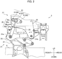
- FIG. 2 a configuration diagram of the cab suspension 3 is illustrated.
- the cab suspension 3 includes a cab hinge unit 21, a cab support member 23, an air spring 25, and a shock absorber unit 27.
- One end of an upper support member 33 rotates around a tilt fulcrum 31a, so that the cab hinge unit 21 can rotate (tilt) the cabin 11 provided above the upper support member 33.
- the cab support member 23 has one end connected to a suspension fulcrum 31b so as to be rotatable, and rotation of the other end is restricted by the air spring 25 and the shock absorber unit 27.
- the cab hinge unit 21 includes a lower support member 31 and the upper support member 33.
- the lower side in the vertical direction of the lower support member 31 is connected to the frame 5.
- the upper side of the lower support member 31 is connected to the upper support member 33 so as to be able to rotate the upper support member 33 at the tilt fulcrum 31a.
- the upper support member 33 has the other end connected to the cab support member 23 so as to be able to rotate the cab support member 23 at the suspension fulcrum 31b.
- the elastic modulus of the air spring 25 is kept constant by air supplied from an air compressor (not illustrated), and is a so-called constituting member of an air suspension that absorbs shock in the pressing direction or the tensile direction in which the shock is applied to the cabin 11.
- a first fastening part 29d of a shock absorber 29 is fixed to the tilt fulcrum 31a.
- a second fastening part 29c is fixed to the cab support member 23 through a resin bracket 41 according to the present invention.
- This shock absorber 29 is an oil damper including a piston rod 29a and a cylinder 29b, and damps force in the piston moving direction, the force being applied to the shock absorber 29 by movement of a piston (not illustrated) connected to the piston rod 29a inside the cylinder 29b.
- the air spring 25 has a constant elastic modulus, so that periodic vibration of a spring mass system generated in the cab support member 23 is damped by the shock absorber 29 of the shock absorber unit 27.
- FIG. 3 a perspective view of the resin bracket 41 according to the present invention is illustrated.
- Fastening counterparts 51 described below are screwed to the cab support member 23 by bolts (fastening members) 65, so that the resin bracket 41 is assembled.
- a cup washer 63, the second fastening part 29c of the shock absorber 29, and a flat washer 67 penetrate a shaft part 47 in the aforementioned order, and are screwed by a nut 61, so that the resin bracket 41 is assembled.
- first fastening part 29d is fixed to the tilt fulcrum 31a
- second fastening part 29c is fixed to the suspension fulcrum 31b, and therefore when the second fastening part 29c performs circular motion around the suspension fulcrum 31b, force in the torsion direction is applied to the first fastening part 29d and the second fastening part 29c.
- an elastic member such as rubber is provided on a peripheral edge of the second fastening part 29c. Consequently, when force in the torsion direction is applied to the second fastening part 29c, the elastic member is warped, so that it is possible to eliminate torsion to be applied to the second fastening part 29c and the first fastening part 29d.
- the resin bracket 41 needs to have a configuration capable of withstanding torsional stress, pressing force, and tensile force to be applied to the load-receiving member 43.
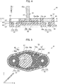
- FIG. 4 a sectional view of a I-I cross section in FIG. 3 is illustrated.
- FIG. 5 a sectional view of a II-II cross section in FIG. 4 is illustrated.
- the resin bracket 41 will be described in detail with reference to FIG. 3 to FIG. 5 .
- the resin bracket 41 includes the load-receiving member 43 and a resin member (main body) 45.
- the load-receiving member 43 is a forged metal member including a flange part (embedded part) 46 and the shaft part 47.
- the flange part 46 is a flat plate member in which a peripheral edge 46b of a flat surface 46a has a hexagonal shape.
- the shaft part 47 extends from the center of the flat surface 46a of the flange part 46 in the direction perpendicular to the flat surface 46a.
- a screw part 47a enabling screwing by the nut 61 is formed on a peripheral surface of an end of the shaft part 47, the end being separated from the flange part 46.
- the resin member 45 is a resin member including the fastening counterparts 51, an outer reinforcement part 53, an inner reinforcement part 55, and an outer edge rib part 57.
- the resin member 45 is so-called fiber reinforced plastic (LEONA 14G manufactured by Asahi Kasei Corporation) formed by using PA66-GF containing glass fiber.
- the aforementioned resin only needs to contain 30% to 50% glass fiber.
- the flange part 46 of the load-receiving member 43 is formed so as to be embedded in a part deeper than a bottom surface 55a of the inner reinforcement part 55 by insert molding.
- the flat surface 46a and the peripheral edge 46b are covered with resin, so that the flange part 46 thus embedded is supported in the direction in which the flange part 46 rotates around the shaft part 47.
- the peripheral edge 46b is supported by the resin member 45, so that it is possible to prevent rotation around the shaft part 47.
- the peripheral edge 46b has a hexagonal shape, so that the peripheral edge 46b can be firmly supported by the resin member 45.
- the fastening counterparts 51 are formed so as to have bearing surfaces 51a and openings 51b, and are provided on both ends of the resin member 45.
- Each bearing surface 51a is a circular surface located in the direction opposite to a Z direction from a front surface 58, and parallel to the front surface 58.
- Each opening 51b is a through hole that penetrates from the center of the bearing surface 51a toward a back surface 59.
- the inner reinforcement part 55, and the outer reinforcement part 53 provided around the inner reinforcement part 55 include bottom surfaces 53a, 55a, and ribs 54, 56, respectively.
- the bottom surfaces 53a, 55a are surfaces that are parallel to the front surface 58, and that are formed to be located in order of the bottom surface 55a and the bottom surface 53a in the direction opposite to the Z direction of the load-receiving member 43 as viewed from the front surface 58.
- the front surface 58 is defined as a first surface L1
- the remaining surfaces are classified into a second surface L2 to a fifth surface L5 in the direction opposite to the Z direction.
- the back surface 59 is defined as a sixth surface L6, the bottom surface 55a and the bottom surface 53a are formed so as to be located at the second surface L2 and a fourth surface L4, respectively.
- a recess 59a recessed from the sixth surface L6 toward the fifth surface L5 is provided at a position corresponding to the outer reinforcement part 53 and the inner reinforcement part 55. Furthermore, the flange part 46 is embedded at a position corresponding to the inner reinforcement part 55 between a third surface L3 and the fourth surface L4, and the thickness in the Z direction between the second surface L2 and the third surface L3 is the same as the thickness between the fourth surface L4 and the fifth surface L5.
- the thickness in the Z direction of resin provided between the respective surfaces forming the bottom surfaces 53a, 55a is uniform, and therefore rigidity and toughness are unified, and stress is distributed.
- the ribs 54, 56 are wall-shaped portions extending in the Z direction from the bottom surfaces 53a, 55a, respectively.
- the rib 56 includes a circular rib 56b concentric with the shaft part 47, and radial ribs 56a radially extending from the shaft part 47.
- grooves 56c are provided at portions near the shaft part 47 of the radial ribs 56a, so that a protrusion 63a of the cup washer 63 can be prevented from interfering with the radial ribs 56a.
- the rib 54 reaches the outer edge rib part 57 forming an outer edge of the resin member 45 from the circular rib 56b.
- This rib 54 includes trunk ribs (radial ribs) 54a radially extending from the shaft part 47, and branch ribs 54b that reach the outer edge rib part 57 from the trunk ribs 54a.
- the radial ribs 56a and the trunk ribs 54a extending radially as viewed from the shaft part 47 are provided in the resin member 45, so that the load-receiving member 43 is reinforced in the direction parallel to the front surface 58 (for convenience of explanation, the direction is hereinafter referred to as an XY flat surface direction).
- the branch ribs 54b reach the outer edge rib part 57 from the trunk ribs 54a, so that the trunk ribs 54a are reinforced with respect to the direction of rotation around a Z-axis.
- the circular rib 56b is provided in the resin member 45, so that the load-receiving member 43 is reinforced with respect to the direction of rotation around the Z-axis.
- the outer reinforcement part 53 and the inner reinforcement part 55 have spaces from the front surface 58 to the bottom surfaces 53a, 55a, respectively, and the load-receiving member 43 is made of resin, so that the resin member 45 is reinforced by the ribs 54, 56 having predetermined flexibility.
- the ribs 54, 56 warp toward the spaces when the load-receiving member 43 is pressed in the XY flat surface direction, or twisted in the direction of rotation around the Z-axis. Consequently, it is possible to distribute stress to be applied to each of the ribs 54, 56.
- the resin bracket 41 in the resin bracket 41 according to the present invention, even in a case where the resin member 45 as the main body is made of resin which is low in material cost and processing cost such as for machining, and torsional stress, pressing force, and tensile force are applied to the load-receiving member 43 by vibration or shock generated by travelling or the like of the truck 1, it is possible to fix the second fastening part 29c of the shock absorber 29 to the cab support member 23 without damage (secure quality).
- the resin bracket according to the present invention includes the resin member 45 made of resin, the fastening counterparts 51 integrally formed with the resin member 45, the metal load-receiving member 43 including the flange part 46 embedded in the resin member 45 and the shaft part 47 extending from the flange part 46, and the outer reinforcement part 53 and the inner reinforcement part 55 as the reinforcement part, having the ribs 54, 56 and provided in the resin member 45.
- the outer reinforcement part 53 and the inner reinforcement part 55 having the ribs 54, 56, respectively are provided in the resin member 45 made of resin, so that the resin member 45 can have moderate toughness and rigidity.
- the trunk ribs 54a and the radial ribs 56a that reach in the direction of force applied to the load-receiving member 43 embedded in the resin member 45 are disposed, so that the load-receiving member 43 can be supported while the trunk ribs 54a and the radial ribs 56a made of the same resin as the resin member 45 moderately warp such that the resin member 45 is not damaged.
- the resin member 45 is of resin, and therefore corrosion resistance can be enhanced, and rust-proofing such as coating is not required.
- the resin member 45 as the main body is of resin, and therefore it is possible to reduce size without considering strength in case of corrosion due to rust or the like.
- the resin member 45 is made of resin, and therefore it is possible to reduce weight and cost compared to a case where a bracket made of metal is formed, for example.
- the load-receiving member 43 made of metal is firmly provided in the resin member 45 made of resin, and it is possible to enhance corrosion resistance without so-called post-treatment such as surface treatment, and form a lightweight and inexpensive bracket.
- the reinforcement part includes the inner reinforcement part 55 in contact with the shaft part 47, and the outer reinforcement part 53 provided around the inner reinforcement part 55, and the height of the rib 56 of the inner reinforcement part 55 in the Z direction from the bottom surface 55a is lower than the height of the rib 54 of the outer reinforcement part 53.
- the height of the rib 56 of the inner reinforcement part 55 on which force to be applied to the load-receiving member 43 is concentrated is reduced, so that it is possible to enhance the rigidity of the resin member 45 in the vicinity of the load-receiving member 43.
- the height of the rib 56 of the outer reinforcement part 53 is increased, so that it is possible to enhance the toughness of the outer reinforcement part 53.
- the rigidity of the inner reinforcement part 55 is enhanced, the toughness of the outer reinforcement part 53 is enhanced, so that the resin member 45 supporting the load-receiving member 43 is reinforced by the inner reinforcement part 55, the inner reinforcement part 55 having enhanced rigidity is provided, the outer reinforcement part 53 having enhanced toughness of the resin member 45 near the inner reinforcement part 55 is provided around the inner reinforcement part 55, and the resin member 45 can be formed so as to moderately have the rigidity and the toughness as the whole of the resin member 45.
- the resin constituting the resin member 45 contains 30% to 50% glass fiber.
- the resin member 45 can maintain the toughness by flexibility as resin while enhancing the rigidity.
- the load-receiving member 43 supports the shock absorber 29 provided at such a position as not to be exposed to high-temperature heat of an engine and the like, and therefore it is possible to support a member to which shearing stress and torsional stress by pressing or tension are applied on a fastening portion.
- the resin bracket 41 is provided in order to support the shock absorber 29 provided in the cab suspension 3 of the truck 1.
- the resin bracket may be provided in order to support a shock absorber for a two-wheeled vehicle or the like, or may be used for a real estate such as a house.
- the resin member 45 is formed of PA66-GF50 containing 50% glass fiber.
- the present invention is not limited to this, and any resin having strength may be used.
- a resin bracket according to a first aspect of the present invention includes: a main body made of resin; a fastening counterpart formed integrally with the main body; a metal load-receiving member having an embedded part embedded in the main body, and a shaft part extending from the embedded part; and a reinforcement part having a rib and provided in the main body.
- the reinforcement part having the rib is provided in the main body made of resin, and therefore the main body can have moderate toughness and rigidity.
- the rib extending in the direction of force applied to the load-receiving member embedded in the main body is disposed, so that the load-receiving member can be reinforced while the rib made of resin moderately warp such that the main body made of resin is not damaged.
- the main body is of resin, and therefore corrosion resistance can be enhanced, and rust-proofing such as coating is not required.
- the main body is of resin, and therefore it is possible to reduce size without considering strength in case of corrosion due to rust or the like.
- the main body is made of resin, and therefore it is possible to reduce weight and cost compared to a case where a bracket made of metal is formed, for example.
- the load-receiving member made of metal is firmly provided in the main body made of resin, and it is possible to enhance corrosion resistance without so-called post-treatment such as surface treatment, and form a lightweight and inexpensive bracket.
- the reinforcement part is provided with a plurality of the ribs. Consequently, it is possible to distribute force to be applied to one rib, and prevent stress concentration.
- the reinforcement part is provided with a bottom surface between the ribs, and the ribs have different heights from the bottom surface in a direction in which the shaft part extends. Consequently, rigidity and toughness can be adjusted by the heights of the ribs.
- the reinforcement part includes an inner reinforcement part in contact with the shaft part, and an outer reinforcement part provided around the inner reinforcement part, and the height of the rib of the inner reinforcement part from the bottom surface in the direction in which the shaft part extends is lower than the height of the rib of the outer reinforcement part. Consequently, the height of the rib of the inner reinforcement part on which force to be applied to the load-receiving member is concentrated is reduced, so that it is possible to enhance the rigidity of the main body near the load-receiving member. On the other hand, the height of the rib of the outer reinforcement part is increased, so that it is possible to enhance the toughness of the outer reinforcement part.
- resin forming the bottom surface in the main body has a uniform thickness in the direction in which the shaft part extends. Consequently, the thickness of the resin forming the bottom surface is uniformed, rigidity or toughness of the resin forming the bottom surface is unified, and stress concentration on a part of the resin forming the bottom surface is suppressed.
- the reinforcement part has a circular rib having a circular shape and surrounding the load-receiving member. Consequently, the load-receiving member is reinforced with respect to the direction of rotation around the shaft part.
- the reinforcement part has a radial rib radially extending from the load-receiving member. Consequently, the load-receiving member is reinforced in the direction along the radial rib from the load-receiving member.
- the reinforcement part further has a branch rib branched from the radial rib. Consequently, the radial rib is reinforced with respect to the direction of rotation around the shaft part.
- the resin constituting the main body contains 30% to 50% glass fiber. Consequently, the main body can maintain the toughness by flexibility as resin while enhancing the rigidity.
- the shaft part is provided with a screw part on a circumferential surface thereof. Consequently, a penetrated member that penetrates the shaft part to be connected can be screwed by providing a nut on the screw part, and the penetrated member can be firmly fastened to the shaft part.
- the load-receiving member is mounted on a shock absorber of a cab suspension, and supports the shock absorber. Consequently, the load-receiving member supports the shock absorber provided at such a position as not to be exposed to high-temperature heat of an engine and the like, so that the main body made of resin can be made not to be exposed to high-temperature heat. Additionally, the main body can support a member to which shearing stress and torsional stress by pressing or tension are applied on a fastening portion such as a shock absorber of the cab suspension through the shaft part.
Landscapes
- Engineering & Computer Science (AREA)
- Mechanical Engineering (AREA)
- General Engineering & Computer Science (AREA)
- Chemical & Material Sciences (AREA)
- Combustion & Propulsion (AREA)
- Transportation (AREA)
- Body Structure For Vehicles (AREA)
- Connection Of Plates (AREA)
- Vehicle Body Suspensions (AREA)
Abstract
Description
- The present invention relates to a resin bracket, and particularly to a technique for improving strength and improving quality.
- Conventionally, a cab suspension has been used to improve ride comfort for a cabin in which a crew of a truck boards. In this cab suspension, an air spring for absorbing shock of the cabin such as an air suspension is provided. Additionally, it is known to use a shock absorber to damp periodic vibration of a spring mass system generated by such an air spring (
Patent Documents 1, 2). -
- Patent Document 1: Japanese Patent Laid-Open No.
7-137667 - Patent Document 2: Japanese Patent Laid-Open No.
11-348819 - For the cab suspension like the
aforementioned Patent Documents 1, 2, a forged metal bracket is used to mount the shock absorber on a cab side. However, the forged bracket has a problem of requirement for machining, coating, and the like, and a high manufacturing cost. - From the above, a problem to be solved in this application is to provide a resin bracket capable of suppressing cost while securing quality.
- A resin bracket according to this application example includes: a main body made of resin; a fastening counterpart formed integrally with the main body; a metal load-receiving member having an embedded part embedded in the main body, and a shaft part extending from the embedded part; and a reinforcement part having a rib and provided in the main body.
- According to the resin bracket according to this application example, the reinforcement part having the rib is provided in the main body made of resin, so that the main body can form an inexpensive bracket having moderate toughness and rigidity. Consequently, it is possible to provide a resin bracket capable of suppressing cost while securing quality.
-
-
FIG. 1 is a schematic configuration diagram of a truck mounted with a cab suspension. -
FIG. 2 is a configuration diagram of the cab suspension. -
FIG. 3 is a perspective view of a resin bracket according to the present invention. -
FIG. 4 is a sectional view of a I-I cross section inFIG. 3 . -
FIG. 5 is a sectional view of a II-II cross section inFIG. 4 . - Hereinafter, an embodiment of the present invention will be described with reference to the drawings.
- Referring to
FIG. 1 , a schematic configuration diagram of atruck 1 mounted with acab suspension 3 is illustrated. - In a front part of the
truck 1, aframe 5,wheels 7, and acabin 11 are provided. Aleaf spring 9 is disposed between theframe 5 and eachwheel 7. Furthermore,cab suspensions 3 are disposed between theframe 5 and thecabin 11. Eachleaf spring 9 is connected to adriving component 13 at a center in the front-rear direction, and is a suspension for absorbing vibration or shock transmitted from thewheel 7 to theframe 5. That is, theleaf spring 9 is disposed in order to suppress deterioration and damage of components mainly composing thetruck 1, such as thedriving component 13, theframe 5, and an engine (not illustrated), due to vibration or shock transmitted from thewheels 7. - The
cab suspension 3 further absorbs vibration or shock transmitted from thewheels 7 to thecabin 11 with a configuration described below. That is, thecab suspensions 3 each are a suspension provided in order to mainly improve ride comfort of a crew who boards thecabin 11. - Referring to
FIG. 2 , a configuration diagram of thecab suspension 3 is illustrated. - The
cab suspension 3 includes acab hinge unit 21, acab support member 23, anair spring 25, and ashock absorber unit 27. One end of anupper support member 33 rotates around atilt fulcrum 31a, so that thecab hinge unit 21 can rotate (tilt) thecabin 11 provided above theupper support member 33. Thecab support member 23 has one end connected to asuspension fulcrum 31b so as to be rotatable, and rotation of the other end is restricted by theair spring 25 and theshock absorber unit 27. - Specifically, the
cab hinge unit 21 includes alower support member 31 and theupper support member 33. The lower side in the vertical direction of thelower support member 31 is connected to theframe 5. The upper side of thelower support member 31 is connected to theupper support member 33 so as to be able to rotate theupper support member 33 at thetilt fulcrum 31a. - The
upper support member 33 has the other end connected to thecab support member 23 so as to be able to rotate thecab support member 23 at thesuspension fulcrum 31b. - The elastic modulus of the
air spring 25 is kept constant by air supplied from an air compressor (not illustrated), and is a so-called constituting member of an air suspension that absorbs shock in the pressing direction or the tensile direction in which the shock is applied to thecabin 11. - In the
shock absorber unit 27, a first fasteningpart 29d of ashock absorber 29 is fixed to thetilt fulcrum 31a. In theshock absorber unit 27, a second fasteningpart 29c is fixed to thecab support member 23 through aresin bracket 41 according to the present invention. This shock absorber 29 is an oil damper including apiston rod 29a and acylinder 29b, and damps force in the piston moving direction, the force being applied to the shock absorber 29 by movement of a piston (not illustrated) connected to thepiston rod 29a inside thecylinder 29b. - That is, in the
cab support member 23, for example, when one end of thecab support member 23 is rotated around thesuspension fulcrum 31b by vibration or shock generated by travelling of thetruck 1, the other end of thecab support member 23 absorbs shock by theair spring 25. Theair spring 25 has a constant elastic modulus, so that periodic vibration of a spring mass system generated in thecab support member 23 is damped by the shock absorber 29 of theshock absorber unit 27. - Referring to
FIG. 3 , a perspective view of theresin bracket 41 according to the present invention is illustrated. Fasteningcounterparts 51 described below are screwed to thecab support member 23 by bolts (fastening members) 65, so that theresin bracket 41 is assembled. Additionally, acup washer 63, the second fasteningpart 29c of the shock absorber 29, and aflat washer 67 penetrate ashaft part 47 in the aforementioned order, and are screwed by anut 61, so that theresin bracket 41 is assembled. - As illustrated in
FIG. 2 , when thecab support member 23 rotates to generate pressing force or tensile force in the shock absorber 29, force in the torsion direction is applied to theresin bracket 41, in addition to pressing force or tensile force in the predetermined direction. Specifically, when thecab support member 23 rotates with thesuspension fulcrum 31b as a base point, the second fasteningpart 29c performs circular motion around thesuspension fulcrum 31b. That is, thefirst fastening part 29d is fixed to thetilt fulcrum 31a, and the second fasteningpart 29c is fixed to thesuspension fulcrum 31b, and therefore when the second fasteningpart 29c performs circular motion around thesuspension fulcrum 31b, force in the torsion direction is applied to the first fasteningpart 29d and the second fasteningpart 29c. - In order to eliminate this torsion, in the second fastening
part 29c and the first fasteningpart 29d, an elastic member such as rubber is provided on a peripheral edge of the second fasteningpart 29c. Consequently, when force in the torsion direction is applied to the second fasteningpart 29c, the elastic member is warped, so that it is possible to eliminate torsion to be applied to the second fasteningpart 29c and thefirst fastening part 29d. - At this time, torsional stress is applied to a load-receiving
member 43, described below, which fixes theresin bracket 41 and the shock absorber 29. Therefore, theresin bracket 41 needs to have a configuration capable of withstanding torsional stress, pressing force, and tensile force to be applied to the load-receivingmember 43. - Referring to
FIG. 4 , a sectional view of a I-I cross section inFIG. 3 is illustrated. Referring toFIG. 5 , a sectional view of a II-II cross section inFIG. 4 is illustrated. Hereinafter, theresin bracket 41 will be described in detail with reference toFIG. 3 to FIG. 5 . - The
resin bracket 41 includes the load-receivingmember 43 and a resin member (main body) 45. The load-receivingmember 43 is a forged metal member including a flange part (embedded part) 46 and theshaft part 47. Theflange part 46 is a flat plate member in which aperipheral edge 46b of aflat surface 46a has a hexagonal shape. - The
shaft part 47 extends from the center of theflat surface 46a of theflange part 46 in the direction perpendicular to theflat surface 46a. Ascrew part 47a enabling screwing by thenut 61 is formed on a peripheral surface of an end of theshaft part 47, the end being separated from theflange part 46. - The
resin member 45 is a resin member including thefastening counterparts 51, anouter reinforcement part 53, aninner reinforcement part 55, and an outeredge rib part 57. - Specifically, for example, the
resin member 45 is so-called fiber reinforced plastic (LEONA 14G manufactured by Asahi Kasei Corporation) formed by using PA66-GF containing glass fiber. The aforementioned resin only needs to contain 30% to 50% glass fiber. - In the
resin member 45, theflange part 46 of the load-receivingmember 43 is formed so as to be embedded in a part deeper than abottom surface 55a of theinner reinforcement part 55 by insert molding. Theflat surface 46a and theperipheral edge 46b are covered with resin, so that theflange part 46 thus embedded is supported in the direction in which theflange part 46 rotates around theshaft part 47. - That is, when the load-receiving
member 43 is twisted in the direction of rotation around theshaft part 47, theperipheral edge 46b is supported by theresin member 45, so that it is possible to prevent rotation around theshaft part 47. Particularly, theperipheral edge 46b has a hexagonal shape, so that theperipheral edge 46b can be firmly supported by theresin member 45. - The
fastening counterparts 51 are formed so as to havebearing surfaces 51a andopenings 51b, and are provided on both ends of theresin member 45. Each bearingsurface 51a is a circular surface located in the direction opposite to a Z direction from afront surface 58, and parallel to thefront surface 58. Eachopening 51b is a through hole that penetrates from the center of the bearingsurface 51a toward aback surface 59. - The
inner reinforcement part 55, and theouter reinforcement part 53 provided around theinner reinforcement part 55 includebottom surfaces ribs front surface 58, and that are formed to be located in order of thebottom surface 55a and thebottom surface 53a in the direction opposite to the Z direction of the load-receivingmember 43 as viewed from thefront surface 58. For convenience of explanation, thefront surface 58 is defined as a first surface L1, the remaining surfaces are classified into a second surface L2 to a fifth surface L5 in the direction opposite to the Z direction. When theback surface 59 is defined as a sixth surface L6, thebottom surface 55a and thebottom surface 53a are formed so as to be located at the second surface L2 and a fourth surface L4, respectively. - In the
back surface 59, arecess 59a recessed from the sixth surface L6 toward the fifth surface L5 is provided at a position corresponding to theouter reinforcement part 53 and theinner reinforcement part 55. Furthermore, theflange part 46 is embedded at a position corresponding to theinner reinforcement part 55 between a third surface L3 and the fourth surface L4, and the thickness in the Z direction between the second surface L2 and the third surface L3 is the same as the thickness between the fourth surface L4 and the fifth surface L5. - That is, the thickness in the Z direction of resin provided between the respective surfaces forming the
bottom surfaces - The
ribs bottom surfaces rib 56 includes acircular rib 56b concentric with theshaft part 47, andradial ribs 56a radially extending from theshaft part 47. Particularly,grooves 56c are provided at portions near theshaft part 47 of theradial ribs 56a, so that aprotrusion 63a of thecup washer 63 can be prevented from interfering with theradial ribs 56a. Therib 54 reaches the outeredge rib part 57 forming an outer edge of theresin member 45 from thecircular rib 56b. Thisrib 54 includes trunk ribs (radial ribs) 54a radially extending from theshaft part 47, andbranch ribs 54b that reach the outeredge rib part 57 from thetrunk ribs 54a. - That is, the
radial ribs 56a and thetrunk ribs 54a extending radially as viewed from theshaft part 47 are provided in theresin member 45, so that the load-receivingmember 43 is reinforced in the direction parallel to the front surface 58 (for convenience of explanation, the direction is hereinafter referred to as an XY flat surface direction). Particularly, thebranch ribs 54b reach the outeredge rib part 57 from thetrunk ribs 54a, so that thetrunk ribs 54a are reinforced with respect to the direction of rotation around a Z-axis. Additionally, thecircular rib 56b is provided in theresin member 45, so that the load-receivingmember 43 is reinforced with respect to the direction of rotation around the Z-axis. - Furthermore, the
outer reinforcement part 53 and theinner reinforcement part 55 have spaces from thefront surface 58 to thebottom surfaces member 43 is made of resin, so that theresin member 45 is reinforced by theribs outer reinforcement part 53 and theinner reinforcement part 55 that reinforce theresin member 45, theribs member 43 is pressed in the XY flat surface direction, or twisted in the direction of rotation around the Z-axis. Consequently, it is possible to distribute stress to be applied to each of theribs - With such a configuration, in the
resin bracket 41 according to the present invention, even in a case where theresin member 45 as the main body is made of resin which is low in material cost and processing cost such as for machining, and torsional stress, pressing force, and tensile force are applied to the load-receivingmember 43 by vibration or shock generated by travelling or the like of thetruck 1, it is possible to fix thesecond fastening part 29c of theshock absorber 29 to thecab support member 23 without damage (secure quality). - As described above, the resin bracket according to the present invention includes the
resin member 45 made of resin, thefastening counterparts 51 integrally formed with theresin member 45, the metal load-receivingmember 43 including theflange part 46 embedded in theresin member 45 and theshaft part 47 extending from theflange part 46, and theouter reinforcement part 53 and theinner reinforcement part 55 as the reinforcement part, having theribs resin member 45. - Accordingly, the
outer reinforcement part 53 and theinner reinforcement part 55 having theribs resin member 45 made of resin, so that theresin member 45 can have moderate toughness and rigidity. For example, thetrunk ribs 54a and theradial ribs 56a that reach in the direction of force applied to the load-receivingmember 43 embedded in theresin member 45 are disposed, so that the load-receivingmember 43 can be supported while thetrunk ribs 54a and theradial ribs 56a made of the same resin as theresin member 45 moderately warp such that theresin member 45 is not damaged. Furthermore, theresin member 45 is of resin, and therefore corrosion resistance can be enhanced, and rust-proofing such as coating is not required. Furthermore, theresin member 45 as the main body is of resin, and therefore it is possible to reduce size without considering strength in case of corrosion due to rust or the like. Particularly, theresin member 45 is made of resin, and therefore it is possible to reduce weight and cost compared to a case where a bracket made of metal is formed, for example. With such a configuration, the load-receivingmember 43 made of metal is firmly provided in theresin member 45 made of resin, and it is possible to enhance corrosion resistance without so-called post-treatment such as surface treatment, and form a lightweight and inexpensive bracket. - The reinforcement part includes the
inner reinforcement part 55 in contact with theshaft part 47, and theouter reinforcement part 53 provided around theinner reinforcement part 55, and the height of therib 56 of theinner reinforcement part 55 in the Z direction from thebottom surface 55a is lower than the height of therib 54 of theouter reinforcement part 53. - Accordingly, the height of the
rib 56 of theinner reinforcement part 55 on which force to be applied to the load-receivingmember 43 is concentrated is reduced, so that it is possible to enhance the rigidity of theresin member 45 in the vicinity of the load-receivingmember 43. On the other hand, the height of therib 56 of theouter reinforcement part 53 is increased, so that it is possible to enhance the toughness of theouter reinforcement part 53. - Thus, while the rigidity of the
inner reinforcement part 55 is enhanced, the toughness of theouter reinforcement part 53 is enhanced, so that theresin member 45 supporting the load-receivingmember 43 is reinforced by theinner reinforcement part 55, theinner reinforcement part 55 having enhanced rigidity is provided, theouter reinforcement part 53 having enhanced toughness of theresin member 45 near theinner reinforcement part 55 is provided around theinner reinforcement part 55, and theresin member 45 can be formed so as to moderately have the rigidity and the toughness as the whole of theresin member 45. - The resin constituting the
resin member 45 contains 30% to 50% glass fiber. - Accordingly, the
resin member 45 can maintain the toughness by flexibility as resin while enhancing the rigidity. - Particularly, the load-receiving
member 43 supports theshock absorber 29 provided at such a position as not to be exposed to high-temperature heat of an engine and the like, and therefore it is possible to support a member to which shearing stress and torsional stress by pressing or tension are applied on a fastening portion. - The description of the resin bracket according to the present invention will be finished. The present invention is not limited to the aforementioned embodiment, and can be changed without departing from the spirit of the invention.
- For example, in this embodiment, the
resin bracket 41 is provided in order to support theshock absorber 29 provided in thecab suspension 3 of thetruck 1. However, the resin bracket may be provided in order to support a shock absorber for a two-wheeled vehicle or the like, or may be used for a real estate such as a house. - In this embodiment, the
resin member 45 is formed of PA66-GF50 containing 50% glass fiber. However, the present invention is not limited to this, and any resin having strength may be used. - A resin bracket according to a first aspect of the present invention includes: a main body made of resin; a fastening counterpart formed integrally with the main body; a metal load-receiving member having an embedded part embedded in the main body, and a shaft part extending from the embedded part; and a reinforcement part having a rib and provided in the main body.
- In the resin bracket according to the first aspect of the present invention, the reinforcement part having the rib is provided in the main body made of resin, and therefore the main body can have moderate toughness and rigidity. For example, the rib extending in the direction of force applied to the load-receiving member embedded in the main body is disposed, so that the load-receiving member can be reinforced while the rib made of resin moderately warp such that the main body made of resin is not damaged. Furthermore, the main body is of resin, and therefore corrosion resistance can be enhanced, and rust-proofing such as coating is not required. Furthermore, the main body is of resin, and therefore it is possible to reduce size without considering strength in case of corrosion due to rust or the like. Particularly, the main body is made of resin, and therefore it is possible to reduce weight and cost compared to a case where a bracket made of metal is formed, for example. With such a configuration, the load-receiving member made of metal is firmly provided in the main body made of resin, and it is possible to enhance corrosion resistance without so-called post-treatment such as surface treatment, and form a lightweight and inexpensive bracket.
- From the above, in the first aspect, it is possible to provide a resin bracket capable of suppressing cost while securing quality.
- According to a resin bracket according to a second aspect of the present invention, in the aforementioned first aspect, the reinforcement part is provided with a plurality of the ribs. Consequently, it is possible to distribute force to be applied to one rib, and prevent stress concentration.
- According to a resin bracket according to a third aspect of the present invention, in the aforementioned second aspect, the reinforcement part is provided with a bottom surface between the ribs, and the ribs have different heights from the bottom surface in a direction in which the shaft part extends. Consequently, rigidity and toughness can be adjusted by the heights of the ribs.
- According to a resin bracket according to a fourth aspect of the present invention, in the aforementioned third aspect, the reinforcement part includes an inner reinforcement part in contact with the shaft part, and an outer reinforcement part provided around the inner reinforcement part, and the height of the rib of the inner reinforcement part from the bottom surface in the direction in which the shaft part extends is lower than the height of the rib of the outer reinforcement part. Consequently, the height of the rib of the inner reinforcement part on which force to be applied to the load-receiving member is concentrated is reduced, so that it is possible to enhance the rigidity of the main body near the load-receiving member. On the other hand, the height of the rib of the outer reinforcement part is increased, so that it is possible to enhance the toughness of the outer reinforcement part.
- According to a resin bracket according to a fifth aspect of the present invention, in the aforementioned third or fourth aspect, resin forming the bottom surface in the main body has a uniform thickness in the direction in which the shaft part extends. Consequently, the thickness of the resin forming the bottom surface is uniformed, rigidity or toughness of the resin forming the bottom surface is unified, and stress concentration on a part of the resin forming the bottom surface is suppressed.
- According to a resin bracket according to a sixth aspect of the present invention, in any of the aforementioned first to fifth aspects, the reinforcement part has a circular rib having a circular shape and surrounding the load-receiving member. Consequently, the load-receiving member is reinforced with respect to the direction of rotation around the shaft part.
- According to a resin bracket according to a seventh aspect of the present invention, in any of the aforementioned first to sixth aspects, the reinforcement part has a radial rib radially extending from the load-receiving member. Consequently, the load-receiving member is reinforced in the direction along the radial rib from the load-receiving member.
- According to a resin bracket according to an eighth aspect of the present invention, in the aforementioned seventh aspect, the reinforcement part further has a branch rib branched from the radial rib. Consequently, the radial rib is reinforced with respect to the direction of rotation around the shaft part.
- According to a resin bracket according to a ninth aspect of the present invention, in any of the aforementioned first to eighth aspects, the resin constituting the main body contains 30% to 50% glass fiber. Consequently, the main body can maintain the toughness by flexibility as resin while enhancing the rigidity.
- According to a resin bracket according to a tenth aspect of the present invention, in any of the aforementioned first to ninth aspects, the shaft part is provided with a screw part on a circumferential surface thereof. Consequently, a penetrated member that penetrates the shaft part to be connected can be screwed by providing a nut on the screw part, and the penetrated member can be firmly fastened to the shaft part.
- According to a resin bracket according to an eleventh aspect of the present invention, in any of the aforementioned first to tenth aspects, the load-receiving member is mounted on a shock absorber of a cab suspension, and supports the shock absorber. Consequently, the load-receiving member supports the shock absorber provided at such a position as not to be exposed to high-temperature heat of an engine and the like, so that the main body made of resin can be made not to be exposed to high-temperature heat. Additionally, the main body can support a member to which shearing stress and torsional stress by pressing or tension are applied on a fastening portion such as a shock absorber of the cab suspension through the shaft part.
-
- 3
- cab suspension
- 29
- shock absorber
- 41
- resin bracket
- 43
- load-receiving member
- 45
- resin member (main body)
- 46
- flange part (embedded part)
- 47
- shaft part
- 47a
- screw part
- 51
- fastening counterpart
- 51a
- bearing surface
- 51b
- opening
- 53
- outer reinforcement part
- 53a, 55a
- bottom surface
- 54, 56
- rib
- 54a
- trunk rib (radial rib)
- 54b
- branch rib
- 55
- inner reinforcement part
- 56a
- radial rib
- 56b
- circular rib
- 65
- bolt (fastening member)
Claims (11)
- A resin bracket comprising:a main body made of resin;a fastening counterpart formed integrally with the main body;a metal load-receiving member having an embedded part embedded in the main body, and a shaft part extending from the embedded part; anda reinforcement part having a rib and provided in the main body.
- The resin bracket according to claim 1, wherein
the reinforcement part is provided with a plurality of the ribs. - The resin bracket according to claim 2, wherein
the reinforcement part is provided with a bottom surface between the ribs, and
the ribs have different heights from the bottom surface in a direction in which the shaft part extends. - The resin bracket according to claim 3, wherein
the reinforcement part includes an inner reinforcement part in contact with the shaft part, and an outer reinforcement part provided around the inner reinforcement part, and
the height of the rib of the inner reinforcement part from the bottom surface in the direction in which the shaft part extends is lower than the height of the rib of the outer reinforcement part. - The resin bracket according to claim 3 or 4, wherein
resin forming the bottom surface in the main body has a uniform thickness in the direction in which the shaft part extends. - The resin bracket according to any one of claims 1 to 5, wherein
the reinforcement part has a circular rib having a circular shape and surrounding the load-receiving member. - The resin bracket according to any one of claims 1 to 6, wherein
the reinforcement part has a radial rib radially extending from the load-receiving member. - The resin bracket according to claim 7, wherein
the reinforcement part further has a branch rib branched from the radial rib. - The resin bracket according to any one of claims 1 to 8, wherein
the resin constituting the main body contains 30% to 50% glass fiber. - The resin bracket according to any one of claims 1 to 9, wherein
the shaft part is provided with a screw part on a circumferential surface thereof. - The resin bracket according to any one of claims 1 to 10, wherein
the load-receiving member is mounted on a shock absorber of a cab suspension, and supports the shock absorber.
Applications Claiming Priority (2)
| Application Number | Priority Date | Filing Date | Title |
|---|---|---|---|
| JP2017210824A JP6913605B2 (en) | 2017-10-31 | 2017-10-31 | Resin bracket |
| PCT/JP2018/040351 WO2019088108A1 (en) | 2017-10-31 | 2018-10-30 | Resin bracket |
Publications (2)
| Publication Number | Publication Date |
|---|---|
| EP3705387A1 true EP3705387A1 (en) | 2020-09-09 |
| EP3705387A4 EP3705387A4 (en) | 2021-08-04 |
Family
ID=66331832
Family Applications (1)
| Application Number | Title | Priority Date | Filing Date |
|---|---|---|---|
| EP18873080.8A Withdrawn EP3705387A4 (en) | 2017-10-31 | 2018-10-30 | Resin bracket |
Country Status (4)
| Country | Link |
|---|---|
| US (1) | US20210179201A1 (en) |
| EP (1) | EP3705387A4 (en) |
| JP (1) | JP6913605B2 (en) |
| WO (1) | WO2019088108A1 (en) |
Family Cites Families (21)
| Publication number | Priority date | Publication date | Assignee | Title |
|---|---|---|---|---|
| JP2535684Y2 (en) * | 1991-09-17 | 1997-05-14 | 三菱自動車工業株式会社 | Hinge cap mounting structure for tilt cab |
| WO1993009302A1 (en) * | 1991-11-06 | 1993-05-13 | Kabushiki Kaisha Komatsu Seisakusho | Resilient supporting device for operator cabin |
| JPH07137667A (en) | 1993-11-15 | 1995-05-30 | Hino Motors Ltd | Cab suspension device for truck |
| US5956053A (en) * | 1996-10-31 | 1999-09-21 | Hewlett-Packard Company | Dual seal capping system for inkjet printheads |
| JPH11348819A (en) | 1998-06-05 | 1999-12-21 | Hino Motors Ltd | Cab suspension structure |
| US6749421B2 (en) * | 2002-02-08 | 2004-06-15 | Formax, Inc. | Patty-forming apparatus |
| JP4734550B2 (en) * | 2004-11-09 | 2011-07-27 | コクヨ株式会社 | Magnet holder |
| KR101440664B1 (en) * | 2007-06-29 | 2014-09-24 | 바스프 에스이 | Basket assembly for a washing machine |
| JP2009127682A (en) * | 2007-11-21 | 2009-06-11 | Fukoku Co Ltd | Air spring |
| CA2788877C (en) * | 2009-02-04 | 2017-06-27 | Thomas M. Espinosa | Concrete anchor |
| US8137041B2 (en) * | 2009-08-05 | 2012-03-20 | 3M Innovative Properties Company | Vibration-isolating fastening assembly |
| US8881478B2 (en) * | 2012-06-22 | 2014-11-11 | Simpson Strong-Tie Company, Inc. | Ratcheting take-up device |
| EP2960567B1 (en) * | 2013-02-20 | 2019-09-25 | Toray Industries, Inc. | Reinforcement structure for structural body having fastening sections |
| US20150114544A1 (en) * | 2013-10-31 | 2015-04-30 | Caterpillar Inc. | Mounting structure and method of attaching mounting structure to surface |
| US9605728B2 (en) * | 2014-04-16 | 2017-03-28 | Zhongli North America, Inc. | Adjustable body mount |
| US9221317B1 (en) * | 2014-07-31 | 2015-12-29 | GM Global Technology Operations LLC | Releasable chassis mount |
| EP3246581B1 (en) * | 2016-05-18 | 2020-07-01 | Grohe AG | Holder for fastening a sanitary component to a wall |
| CA3029820A1 (en) * | 2016-07-06 | 2018-01-11 | Sonoco Development, Inc. | Reel made of molded components |
| US10378569B2 (en) * | 2017-10-25 | 2019-08-13 | Caterpillar Inc. | Adhesive based mounting structure |
| US10647364B2 (en) * | 2018-03-27 | 2020-05-12 | Deere & Company | Vehicle cab tilt apparatus |
| US11193295B1 (en) * | 2019-08-16 | 2021-12-07 | Richard Proctor | Shrinkage compensating device for seismic restraint |
-
2017
- 2017-10-31 JP JP2017210824A patent/JP6913605B2/en active Active
-
2018
- 2018-10-30 US US16/760,603 patent/US20210179201A1/en not_active Abandoned
- 2018-10-30 WO PCT/JP2018/040351 patent/WO2019088108A1/en not_active Ceased
- 2018-10-30 EP EP18873080.8A patent/EP3705387A4/en not_active Withdrawn
Also Published As
| Publication number | Publication date |
|---|---|
| US20210179201A1 (en) | 2021-06-17 |
| JP6913605B2 (en) | 2021-08-04 |
| JP2019081499A (en) | 2019-05-30 |
| EP3705387A4 (en) | 2021-08-04 |
| WO2019088108A1 (en) | 2019-05-09 |
Similar Documents
| Publication | Publication Date | Title |
|---|---|---|
| US6386309B1 (en) | Mount assembly for automotive power plant | |
| CN1629510A (en) | shock absorber | |
| US8210596B2 (en) | Vehicle door with door beam | |
| US20140306418A1 (en) | Method for producing an air guide for a suspension arm and suspension arm with an air guide | |
| CN1295094C (en) | Power plant mounting appts. | |
| US10427481B2 (en) | Motor vehicle wheel suspension | |
| US8550315B2 (en) | Spare tire carrier vibration damper | |
| CN115734911A (en) | Longitudinal beam for rear part of motor vehicle and rear part of motor vehicle | |
| US8696003B2 (en) | Front axle support with arrangement of a steering gear and a front axle stabilizer | |
| US20070235274A1 (en) | Composite helmet for body mount | |
| RU2758728C2 (en) | Monoblock device for supporting power plant, containing intermediate support | |
| EP3065962B1 (en) | Torque roll axis mounting system for serial range extenders without a through-drive | |
| CN114802463A (en) | Interface bracket for electric vehicle strut tower to body structure | |
| US9868329B2 (en) | Spring bracket arm | |
| US20150219146A1 (en) | Wheel suspension bearing, wheel suspension bearing assembly and motor vehicle | |
| GB2534240A (en) | Bushing, in particular for a vehicle | |
| EP4219264B1 (en) | Frame structure for a bogie | |
| US20210179201A1 (en) | Resin bracket | |
| US20170120708A1 (en) | Vehicle spring assembly | |
| KR20160034207A (en) | Stiffening element | |
| JP6967940B2 (en) | Resin bracket | |
| US20190285134A1 (en) | Anti-Vibratory Support For A Motor Vehicle And Motor Vehicle Equipped With Same | |
| CN109050227B (en) | Suspension assembly for vehicle | |
| US8801014B2 (en) | Rear wheel suspension | |
| CN219947816U (en) | Lightweight automobile shock absorber support |
Legal Events
| Date | Code | Title | Description |
|---|---|---|---|
| STAA | Information on the status of an ep patent application or granted ep patent |
Free format text: STATUS: THE INTERNATIONAL PUBLICATION HAS BEEN MADE |
|
| PUAI | Public reference made under article 153(3) epc to a published international application that has entered the european phase |
Free format text: ORIGINAL CODE: 0009012 |
|
| STAA | Information on the status of an ep patent application or granted ep patent |
Free format text: STATUS: REQUEST FOR EXAMINATION WAS MADE |
|
| 17P | Request for examination filed |
Effective date: 20200409 |
|
| AK | Designated contracting states |
Kind code of ref document: A1 Designated state(s): AL AT BE BG CH CY CZ DE DK EE ES FI FR GB GR HR HU IE IS IT LI LT LU LV MC MK MT NL NO PL PT RO RS SE SI SK SM TR |
|
| AX | Request for extension of the european patent |
Extension state: BA ME |
|
| DAV | Request for validation of the european patent (deleted) | ||
| DAX | Request for extension of the european patent (deleted) | ||
| A4 | Supplementary search report drawn up and despatched |
Effective date: 20210705 |
|
| RIC1 | Information provided on ipc code assigned before grant |
Ipc: B62D 33/067 20060101AFI20210629BHEP Ipc: F16B 5/02 20060101ALI20210629BHEP Ipc: B62D 33/06 20060101ALI20210629BHEP |
|
| GRAP | Despatch of communication of intention to grant a patent |
Free format text: ORIGINAL CODE: EPIDOSNIGR1 |
|
| STAA | Information on the status of an ep patent application or granted ep patent |
Free format text: STATUS: GRANT OF PATENT IS INTENDED |
|
| INTG | Intention to grant announced |
Effective date: 20230526 |
|
| STAA | Information on the status of an ep patent application or granted ep patent |
Free format text: STATUS: THE APPLICATION IS DEEMED TO BE WITHDRAWN |
|
| 18D | Application deemed to be withdrawn |
Effective date: 20231006 |