EP3705371A1 - Obstacle detecting device - Google Patents
Obstacle detecting device Download PDFInfo
- Publication number
- EP3705371A1 EP3705371A1 EP18872331.6A EP18872331A EP3705371A1 EP 3705371 A1 EP3705371 A1 EP 3705371A1 EP 18872331 A EP18872331 A EP 18872331A EP 3705371 A1 EP3705371 A1 EP 3705371A1
- Authority
- EP
- European Patent Office
- Prior art keywords
- obstacle
- monitoring region
- railway vehicle
- image
- rail
- Prior art date
- Legal status (The legal status is an assumption and is not a legal conclusion. Google has not performed a legal analysis and makes no representation as to the accuracy of the status listed.)
- Withdrawn
Links
Images





Classifications
-
- B—PERFORMING OPERATIONS; TRANSPORTING
- B61—RAILWAYS
- B61L—GUIDING RAILWAY TRAFFIC; ENSURING THE SAFETY OF RAILWAY TRAFFIC
- B61L23/00—Control, warning or like safety means along the route or between vehicles or trains
- B61L23/04—Control, warning or like safety means along the route or between vehicles or trains for monitoring the mechanical state of the route
- B61L23/041—Obstacle detection
-
- G—PHYSICS
- G06—COMPUTING OR CALCULATING; COUNTING
- G06T—IMAGE DATA PROCESSING OR GENERATION, IN GENERAL
- G06T7/00—Image analysis
- G06T7/0002—Inspection of images, e.g. flaw detection
- G06T7/0004—Industrial image inspection
- G06T7/0008—Industrial image inspection checking presence/absence
-
- G—PHYSICS
- G06—COMPUTING OR CALCULATING; COUNTING
- G06V—IMAGE OR VIDEO RECOGNITION OR UNDERSTANDING
- G06V20/00—Scenes; Scene-specific elements
- G06V20/50—Context or environment of the image
- G06V20/56—Context or environment of the image exterior to a vehicle by using sensors mounted on the vehicle
- G06V20/58—Recognition of moving objects or obstacles, e.g. vehicles or pedestrians; Recognition of traffic objects, e.g. traffic signs, traffic lights or roads
-
- B—PERFORMING OPERATIONS; TRANSPORTING
- B61—RAILWAYS
- B61L—GUIDING RAILWAY TRAFFIC; ENSURING THE SAFETY OF RAILWAY TRAFFIC
- B61L25/00—Recording or indicating positions or identities of vehicles or trains or setting of track apparatus
- B61L25/02—Indicating or recording positions or identities of vehicles or trains
- B61L25/025—Absolute localisation, e.g. providing geodetic coordinates
-
- G—PHYSICS
- G06—COMPUTING OR CALCULATING; COUNTING
- G06T—IMAGE DATA PROCESSING OR GENERATION, IN GENERAL
- G06T2207/00—Indexing scheme for image analysis or image enhancement
- G06T2207/10—Image acquisition modality
- G06T2207/10016—Video; Image sequence
- G06T2207/10021—Stereoscopic video; Stereoscopic image sequence
-
- G—PHYSICS
- G06—COMPUTING OR CALCULATING; COUNTING
- G06T—IMAGE DATA PROCESSING OR GENERATION, IN GENERAL
- G06T2207/00—Indexing scheme for image analysis or image enhancement
- G06T2207/20—Special algorithmic details
- G06T2207/20021—Dividing image into blocks, subimages or windows
-
- G—PHYSICS
- G06—COMPUTING OR CALCULATING; COUNTING
- G06T—IMAGE DATA PROCESSING OR GENERATION, IN GENERAL
- G06T2207/00—Indexing scheme for image analysis or image enhancement
- G06T2207/30—Subject of image; Context of image processing
- G06T2207/30232—Surveillance
-
- G—PHYSICS
- G06—COMPUTING OR CALCULATING; COUNTING
- G06T—IMAGE DATA PROCESSING OR GENERATION, IN GENERAL
- G06T2207/00—Indexing scheme for image analysis or image enhancement
- G06T2207/30—Subject of image; Context of image processing
- G06T2207/30236—Traffic on road, railway or crossing
-
- G—PHYSICS
- G06—COMPUTING OR CALCULATING; COUNTING
- G06T—IMAGE DATA PROCESSING OR GENERATION, IN GENERAL
- G06T2207/00—Indexing scheme for image analysis or image enhancement
- G06T2207/30—Subject of image; Context of image processing
- G06T2207/30248—Vehicle exterior or interior
- G06T2207/30252—Vehicle exterior; Vicinity of vehicle
Definitions
- Embodiments of the present invention relate to an obstacle detection device.
- a station platform fence for preventing the penetration of an obstacle
- a railway crossing gate for preventing the penetration of an obstacle
- a station platform fall detection device such as a pressure-sensitive mat for detecting the presence of an obstacle or an image recognition device for recognizing an image of an obstacle
- an obstacle detection device of an optical type, a loop coil type, or the like for detecting the presence of an obstacle at a railway crossing, or the like is installed in some cases.
- an emergency stop alarm button for notifying the occurrence of a train or station emergency or the like is set in some cases.
- the foregoing equipment is installed in only sections in which an obstacle is likely to exist, in the route of railway vehicles, and it is difficult to cover the entire route of the railway vehicles.
- ground equipment and on-vehicle equipment are required to coordinate with each other when using the foregoing equipment, there is a concern that systems are made more complex and are increased in size. Therefore, a system for detecting an obstacle exists has been developed. In the system, images in the traveling direction of a railway vehicle continuously captured by an imaging unit, mounted on the railway vehicle, is used to detect the obstacle.
- the idling distance is a distance that the railway vehicle travels from a time the driver or the foregoing equipment recognizes the obstacle to a time braking is applied
- the braking distance is a distance that the railway vehicle travels from the time the braking is applied to a time the railway vehicle stops.
- the railway vehicle compared with a car's collision avoidance system, the railway vehicle has a different feature that the railway vehicle cannot avoid an obstacle by steering due to restrictions such as a long braking distance and traveling on a rail. Therefore, the railway vehicle is requested to detect an obstacle present on a rail enough far away from the obstacle with high accuracy.
- An obstacle detection device includes an acquiring unit, a rail detector, a monitoring region setting unit, an obstacle detector, and an output unit.
- the acquiring unit acquires a visible light image obtained by imaging in a traveling direction of a railway vehicle by an imaging unit included in the railway vehicle and a distance image that allows a distance to an object existing in an imaging range of the imaging unit to be identifiable.
- the rail detector detects, from the visible light image, a rail on which the railway vehicle travels.
- the monitoring region setting unit uses the rail as a standard to set, in the visible light image, a three-dimensional monitoring region defined by a loading gauge of the railway vehicle or a construction gauge.
- the obstacle detector detects an obstacle that exists in the monitoring region and hinders the traveling of the railway vehicle, based on range information that allows a distance range to the monitoring region based on the visible light image to be identifiable and the distance image.
- the output unit that outputs a result of detecting the obstacle.
- FIG. 1 is a diagram illustrating an example of a schematic configuration of a railway vehicle according to a first embodiment.
- the railway vehicle RV includes a sensor 10, an obstacle detection device 20, a storage 30, and a display 40.
- the sensor 10 is an example of an imaging unit that can capture an image in a traveling direction of the railway vehicle RV. In the present embodiment, the sensor 10 can capture an image in an imaging range including a rail R existing in the traveling direction of the railway vehicle RV.
- the obstacle detection device 20 is just an example for detecting an obstacle that hinders the traveling of the railway vehicle RV.
- the storage 30 stores a result of detecting an obstacle by the obstacle detection device 20.
- the display 40 displays an image obtained by imaging in the traveling direction of the railway vehicle RV by the sensor 10 and various types of information such as a result of detecting an obstacle by the obstacle detection device 20.
- FIG. 2 is a block diagram illustrating an example of a functional configuration of the obstacle detection device included in the railway vehicle according to the first embodiment.
- the obstacle detection device 20 includes an image acquiring unit 201, a rail recognizing unit 202, a monitoring area recognizing unit 203, a candidate obstacle recognizing unit 204, an obstacle determining unit 205, a result output unit 206, and a storage 207.
- a part of or all of the image acquiring unit 201, the rail recognizing unit 202, the monitoring area recognizing unit 203, the candidate obstacle recognizing unit 204, the obstacle determining unit 205, and the result output unit 206 are achieved by causing a processor such as a central processing unit (CPU) included in the railway vehicle RV to execute software stored in the storage 207.
- a processor such as a central processing unit (CPU) included in the railway vehicle RV to execute software stored in the storage 207.
- the part of or all of the image acquiring unit 201, the rail recognizing unit 202, the monitoring area recognizing unit 203, the candidate obstacle recognizing unit 204, the obstacle determining unit 205, and the result output unit 206 may be achieved by hardware that is a circuit board such as large scale integration (LSI), an application specific integrated circuit (ASIC), or a field programmable gate array (FPGA).
- LSI large scale integration
- ASIC application specific integrated circuit
- FPGA field programmable gate array
- the image acquiring unit 201, the rail recognizing unit 202, the monitoring area recognizing unit 203, the candidate obstacle recognizing unit 204, the obstacle determining unit 205, and the result output unit 206 may be achieved by causing the software executed by the processor and the hardware to collaborate with each other.
- the storage 207 includes a nonvolatile storage medium such as a read only memory (ROM), a flash memory, a hard disk drive (HDD), or an SD card, and a volatile storage medium such as a random access memory (RAM) or a register.
- the storage 207 stores various types of information such as a computer program to be executed by the processor included in the railway vehicle RV.
- the image acquiring unit 201 is an example of an acquiring unit that acquires a visible light image (hereinafter referred to as color image) obtained by imaging in the traveling direction of the railway vehicle RV by the sensor 10 and a distance image for identifying a distance to an object existing in the imaging range of the sensor 10.
- the image acquiring unit 201 acquires, as the color image, any one of a plurality of images obtained by imaging in the traveling direction of the railway vehicle RV by a plurality of imaging units included in the sensor 10 from different points of view.
- the image acquiring unit 201 acquires the images as the distance image.
- the image acquiring unit 201 converts the images obtained by the imaging by the imaging units included in the sensor 10 into gray-scaled images (hereinafter referred to as grayscale images).
- the image acquiring unit 201 geometrically converts the grayscale images into images (hereinafter referred to as parallel coordinate images) obtained when optical axes of the imaging units are virtually parallel to each other.
- the image acquiring unit 201 uses, in accordance with the principles of parallel stereo vision, one of the parallel coordinate images and the other of the parallel coordinate images to acquire the distance image for identifying the distance to the object existing in the imaging range of the imaging units included in the sensor 10.
- the rail recognizing unit 202 functions as an example of a rail detector that detects the rail R that is in the color image and on which the railway vehicle RV travels.
- the rail recognizing unit 202 converts each of the grayscale images converted from the color images obtained by the imaging by the sensor 10 into an image (hereinafter referred to as edge-highlighted image) with edges highlighted. Then, the rail recognizing unit 202 generates pixel groups by grouping certain pixels that are in the edge-highlighted image and have certain edge intensities larger than a predetermined edge intensity and pixels that are in pixels around the certain pixels and have edge intensities equal to or nearly equal to the certain edge intensities.
- the rail recognizing unit 202 extracts, from the generated pixel groups, pixel groups forming continuous lines extending in the traveling direction of the railway vehicle RV. Then, the rail recognizing unit 202 detects, from among the extracted pixel groups, pixel groups satisfying a predetermined evaluation condition as the rail R on which the railway vehicle RV travels.
- the evaluation condition is that pixel groups are determined to be the rail R, for example, the pixel groups having edge intensities determined to be the rail R.
- the monitoring area recognizing unit 203 functions as an example of a monitoring region setting unit that sets a three-dimensional monitoring region in the color image using the rail R detected by the rail recognizing unit 202 as a standard.
- the monitoring region is a three-dimensional region defined by a loading gauge of the railway vehicle RV or a construction gauge in the color image.
- the monitoring area recognizing unit 203 calculates, based on the color image, range information for identifying a range that is a distance range from the sensor 10 to the monitoring region.
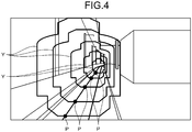
- FIGS. 3 and 4 are diagrams illustrating examples of the monitoring region set for the railway vehicle according to the first embodiment.
- the monitoring area recognizing unit 203 calculates loading gauge cross-sections X and distances to the loading gauge cross-sections X for arbitrary positions P on the detected rail R based on installation conditions of the sensor 10 and restrictions including a condition that a width of the rail R detected by the rail recognizing unit 202 is constant.
- Each of the loading gauge cross-sections X is a cross-section of the loading gauge in a direction perpendicular to the traveling direction of the railway vehicle RV.
- the monitoring area recognizing unit 203 sets, as the monitoring region, a tunnel-shaped region with cross-sections that are the loading gauge cross-sections X calculated for the different positions P on the rail R in the traveling direction of the railway vehicle RV. In addition, the monitoring area recognizing unit 203 calculates, as range information, a range that is a range (set) of distances to the loading gauge cross-sections X calculated for the positions P.
- the monitoring area recognizing unit 203 calculates construction cross-sections Y and distances to the construction gauge cross-sections Y for arbitrary positions P on the detected rail R based on the installation conditions of the sensor 10 and restrictions including the condition that the width of the rail R detected by the rail recognizing unit 202 is constant.
- Each of the construction gauge cross-sections Y is a cross-section of the construction gauge in the direction perpendicular to the traveling direction of the railway vehicle RV.
- the monitoring area recognizing unit 203 sets, as the monitoring region, a tunnel-shaped region with cross-sections that are the construction gauge cross-sections Y calculated for the different positions P on the rail R in the traveling direction of the railway vehicle RV.
- the monitoring area recognizing unit 203 calculates, as range information, a range that is a range (set) of distances to the construction gauge cross-sections Y calculated for the positions P.
- the candidate obstacle recognizing unit 204 extracts, as candidates (hereinafter referred to as candidate obstacles) of an obstacle, objects in the monitoring region based on the distance image and the range information.
- the candidate obstacle recognizing unit 204 extracts, as a three-dimensional candidate obstacle existing in the monitoring region, a similar region obtained by grouping pixels from among pixels within the distance image and indicating distances matching the distances identified by the range information.
- the obstacle determining unit 205 detects an obstacle from the candidate obstacles based on at least one of sizes of the candidate obstacles extracted by the candidate obstacle recognizing unit 204 and moving vectors of the candidate obstacles. Therefore, because it is possible to detect, as an obstacle, an object that is likely to be an obstacle from among objects existing in the monitoring region, the accuracy of detecting the obstacle can be improved.
- the obstacle determining unit 205 detects, as an obstacle, a candidate obstacle that is among the candidate obstacles and has a size equal to or larger than a size set in advance.
- the obstacle determining unit 205 detects, as an obstacle, a candidate obstacle that is among the candidate obstacles and has a moving vector pointing toward the rail R.
- the obstacle determining unit 205 may detect, as an obstacle, a candidate obstacle that is among the candidate obstacles and has a size equal to or larger than the size set in advance and a moving vector pointing toward the rail R.
- the candidate obstacle recognizing unit 204 and the obstacle determining unit 205 collaborate with each other to function as an example of an obstacle detector that detects, based on the distance image and the range information, an obstacle that is in the monitoring region and hinders the traveling of the railway vehicle RV. Therefore, when the color image obtained by the imaging in the traveling direction of the railway vehicle RV is used to detect an obstacle that hinders the traveling of the railway vehicle RV, it is possible to dynamically and approximately set the monitoring region from which the obstacle is detected in the color image and to detect the obstacle, and thus the obstacle that hinders the traveling of the railway vehicle RV can be detected with high accuracy.
- the result output unit 206 functions as an example of an output unit that outputs a result of detecting an obstacle by the candidate obstacle recognizing unit 204 and the obstacle determining unit 205.
- the result output unit 206 when an obstacle is detected by the obstacle determining unit 205, the result output unit 206 causes the display 40 to display the color image and information indicating that the obstacle has been detected.
- the result output unit 206 stores the result of detecting the obstacle in the storage 30.
- FIG. 5 is a flowchart indicating the example of the process of detecting an obstacle in the railway vehicle according to the first embodiment.
- the image acquiring unit 201 acquires the color image and the distance image from the sensor 10 (in step S501).
- the sensor 10 is an optical sensor that can simultaneously output the color image and the distance image and is an optical sensor of pattern projection type, photogrammetry type, or time-of-flight type.
- the image acquiring unit 201 may acquire, as the distance image, two color images obtained by imaging by the two imaging units.
- the image acquiring unit 201 Upon acquiring the two color images, as the distance image, the image acquiring unit 201 converts the two color images into grayscale images (in step S502).
- the present embodiment describes an example in which the image acquiring unit 201 converts the two color images into the grayscale images to reduce a calculation amount necessary to detect an obstacle and uses the grayscale images to detect the obstacle.
- the obstacle can be detected using the color images as they are.
- the image acquiring unit 201 geometrically transforms the two grayscale images into parallel coordinate images (in step S503).
- a general camera lens has a distortion in a radial direction and a distortion in a circumferential direction. Therefore, a coefficient and/or a table that are necessary to correct distortions of images obtained by imaging by the sensor 10 is stored, as image conversion information, in the storage 207. Then, the image acquiring unit 201 can use the image conversion information stored in the storage 207 to correct distortions of the grayscale images based on aberration of lenses or the like.
- an internal parameter of the sensor 10 and an external parameter based on relative positional relations may be calculated by calibration, and the external parameter may be stored as the image conversion information in the storage 207.
- the image acquiring unit 201 uses one of the parallel coordinate images as a standard image and the other of the parallel coordinate images as a reference image to calculate disparity between the standard image and the reference image as the distance image (in step S504).
- a geometrical restrictions such as epipolar geometry
- a corresponding pixel in the reference image, corresponding to a target pixel in the standard image is calculated by searching only an epipolar line at the same height position as that of the target pixel of the standard image. Therefore, the corresponding pixel can be searched with a small calculation amount and with high accuracy.
- the search of the corresponding pixel is executed by template matching, global matching, semi-global matching, or the like.
- the corresponding pixel is searched from each of small regions that are some regions within the reference image.
- the optimal corresponding pixel (solution) is searched from the entire reference image.
- the optimal corresponding pixel is searched from pixels around the target pixel in the reference image.
- the corresponding pixel is searched by the template matching in many cases.
- the image acquiring unit 201 calculates the disparity between the target pixel of the standard image and the corresponding pixel of the reference image.
- the image acquiring unit 201 calculates the corresponding pixel of the reference image while shifting the target pixel of the standard image one by one. Therefore, when the reference image is a digital image, coordinates of the corresponding pixel are represented by integers. Therefore, when the coordinates of the corresponding pixel are estimated with decimal precision, a subpixel estimation method is used.
- an evaluation function to be used to search for the corresponding pixel is a primary function such as the sum of absolute difference (SAD), equiangular linear fitting is used.
- the evaluation function to be used to search for the corresponding pixel is a secondary function such as the sum of squared difference (SSD), parabola fitting is used.
- the disparity may be calculated without using the subpixel estimation method.
- an evaluation value of the coordinates of the corresponding pixel that is based on the evaluation function used in the subpixel estimation method is larger than a predetermined threshold, and a difference between characteristic amounts (for example, changes in gradations) of the target pixel and the corresponding pixel is small, the calculated disparity may be invalidated.
- the image acquiring unit 201 calculates disparity between pixels of the reference image and all pixels of the standard image or pixels in a valid region of a part of the standard image. Then, the image acquiring unit 201 uses the following Equation (1) to calculate, as the distance image, a distance Z to an object indicated by pixels of the standard image.
- Equation (1) f indicates a focal distance of the two imaging units included in the sensor 10
- B indicates a distance between the two imaging units included in the sensor 10
- D indicates disparity D between a pixel of the standard image and a pixel of the reference image.
- Z f ⁇ B / D
- the rail recognizing unit 202 detects candidate rails that are candidates of the rail R on which the railway vehicle RV travels (in step S505).
- the rail recognizing unit 202 converts the standard image into an edge-highlighted image.
- the rail recognizing unit 202 detects, as the candidate rails, pixel groups forming continuous lines extending in the traveling direction of the railway vehicle RV from pixel groups obtained by grouping certain pixels having certain edge intensities larger than the predetermined edge intensity and pixels existing around the certain pixels and having edge intensities equal to or nearly equal to the certain edge intensities in the edge-highlighted image.
- the rail recognizing unit 202 detects, as the rail R, a candidate rail satisfying the evaluation condition set in advance from the detected candidate rails (in step S506).
- the monitoring area recognizing unit 203 uses the rail R detected by the rail recognizing unit 202 as a standard and sets a three-dimensional monitoring region in the standard image (in step S507).
- FIG. 6 is a schematic diagram illustrating an example of a method for setting the monitoring region in the railway vehicle according to the first embodiment.
- the monitoring area recognizing unit 203 sets, for any arbitrary position P on the rail R detected by the rail recognizing unit 202, a horizontal line connecting left and right segments of the rail R and existing at the position P.
- the line has a length of L pixels in the standard image.
- pitch angles, yaw angles, and roll angles of the imaging units included in the sensor 10 are all 0°, and the rail R on which the railway vehicle RV travels has a narrow gauge, resolution per pixel in the horizontal direction is 1067/L millimeters.
- the monitoring area recognizing unit 203 uses the distance image to acquire disparity between a target pixel at the position P and a corresponding pixel or a distance to the position P. Then, the monitoring area recognizing unit 203 calculates resolution per pixel based on the disparity or the distance in advance and identifies resolution per pixel based on the acquired disparity or the acquired distance. Then, the monitoring area recognizing unit 203 may treat the identified resolution per pixel as resolution per pixel in the horizontal direction at the position P. When aspect ratios of imaging elements of the sensor 10 are 1:1, resolution per pixel in a direction (or vertical direction) perpendicular to the line is the same as the resolution per pixel in the horizontal direction.
- the monitoring area recognizing unit 203 sets a loading gauge cross-section X for each of the positions P within the standard image based on dimensions (for example, a width: 3800 mm, a height: 4300 mm) of the loading gauge in the actual space and the resolution per pixel in the standard image.
- the monitoring area recognizing unit 203 sets a region imitating a cross-section of the loading gauge as the loading gauge cross-section X, but is not limited to this as long as a region that allows the loading gauge to be identifiable is set as the loading gauge cross-section X.
- the monitoring area recognizing unit 203 may set, as the loading gauge cross-section X, a region of a predetermined shape, such as a rectangle approximating the cross-section of the loading gauge.
- a region of a predetermined shape such as a rectangle approximating the cross-section of the loading gauge.
- the loading gauge cross-section X is set in the standard image
- the monitoring area recognizing unit 203 sets a tunnel-shaped monitoring region in the standard image by repeatedly setting the loading gauge cross-section X for each of the positions P while moving the positions P within the standard image in the traveling direction of the railway vehicle RV.
- the monitoring area recognizing unit 203 calculates, for each of the positions P, a distance to the position P or the disparity between a target pixel at the position P and a corresponding pixel based on the resolution per pixel in the standard image, the number of pixels in a range from a lower end (or an end on the near side in the imaging range of the sensor 10) of the standard image to the position P, and the like. Then, the monitoring area recognizing unit 203 treats, as range information, a range of distances calculated for the positions P or a range of disparity calculated for the positions P. In addition, the monitoring area recognizing unit 203 stores the range information, as monitoring area information, in the storage 207.
- the candidate obstacle recognizing unit 204 sets, in the standard image, a standard plane in contact with an upper surface of the rail R detected by the rail recognizing unit 202 (in step S508). Therefore, an object that exists under the rail R and is unlikely to be an obstacle is not detected as a candidate obstacle, and thus a processing load caused by the process of detecting an obstacle can be reduced.
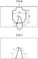
- FIG. 7 is a diagram illustrating an example of a process of setting the standard plane for the railway vehicle according to the first embodiment.
- the candidate obstacle recognizing unit 204 sets, as standard planes P1 and P2, approximate flat or curved planes along a part of the upper surface of the rail R recognized by the rail recognizing unit 202 and the part of the upper surface is in an area close to the sensor 10 or an area with similar disparity.
- the candidate obstacle recognizing unit 204 extracts, as candidate obstacles, objects in the monitoring region of the standard image based on the distance image indicating the disparity (or distance) between the standard image and the reference image, and the range information (in step S509). Specifically, as candidate obstacles, the candidate obstacle recognizing unit 204 extracts objects, from the objects in the standard image, having a disparity between the standard image and the reference image or a distance within the range indicated in the range information.
- the candidate obstacle recognizing unit 204 extracts, as a candidate obstacle, an object existing above the standard plane. Specifically, among the objects in the monitoring region of the standard image, the candidate obstacle recognizing unit 204 extracts, as a candidate obstacle, an object residing on the near side with respect to the standard plane, or an object closer the sensor 10 than the standard plane (or an object having larger disparity than disparity of the standards plane).
- the obstacle determining unit 205 detects an obstacle from among the candidate obstacles based on at least one of sizes of the candidate obstacles and moving vectors of the candidate obstacles (in step S510). In the present embodiment, the obstacle determining unit 205 discards, as noise or disturbance, any candidate obstacle, among the candidate obstacles, having an aspect ratio of a circumscribed rectangle that is extremely biased in the standard image. In addition, the obstacle determining unit 205 calculates a moving vector of a candidate obstacle between standard images of two or more frames among the candidate obstacles. When the moving vector points from the lower side to the upper side, the obstacle determining unit 205 discards the obstacle as disturbance such as a bird or smoke. Then, the obstacle determining unit 205 detects, as an obstacle, a candidate obstacle that is among the candidate obstacles and remains without being discarded and has the center of gravity the position of which is in the monitoring region.
- the result output unit 206 outputs, to the display 40, a result of detecting the obstacle by the obstacle determining unit 205 and causes the display 40 to display the result of detecting the obstacle (in step S511).
- the result output unit 206 causes the display 40 to display, as the result of detecting the obstacle, the fact that the obstacle has been detected by the obstacle determining unit 205, a distance to the detected obstacle, and the like.
- the result output unit 206 outputs audio notifying the result of detecting the obstacle and outputs the result of detecting the obstacle to a vehicle control device for controlling the traveling of the railway vehicle RV.
- the result output unit 206 stores detection result information indicating the result of detecting the obstacle in the storage 207.
- the result output unit 206 can store the detection result information in an external storage. Therefore, even in an offline state where an external device cannot communicate with the obstacle detection device 20 of the railway vehicle RV, the external device can use the detection result information stored in the external storage to analyze the result of detecting the obstacle.
- the image acquiring unit 201 determines whether the termination of the process of detecting an obstacle is instructed (in step S512). When the termination of the process of detecting an obstacle is instructed (Yes at step S512), the image acquiring unit 201 does not acquire a new color image and a distance image and terminates the process of detecting an obstacle. In contrast, when the termination of the process of detecting an obstacle has not been instructed (No at step S512), the image acquiring unit 201 returns to step S501 and acquires the new color image and the distance image.
- the railway vehicle RV of the first embodiment when the color image obtained by the imaging in the traveling direction of the railway vehicle RV is used to detect an obstacle that hinders the traveling of the railway vehicle RV, it is possible to dynamically and appropriately set the monitoring region from which the obstacle is detected in the color image and detect the obstacle. Therefore, the obstacle that hinders the traveling of the railway vehicle RV can be detected with high accuracy.
- a modification is an example in which when a plurality of rails are detected from a color image, a monitoring region is set for each of the rails using the rails as standards.
- the following describes different features from the first embodiment.
- FIG. 8 is a diagram illustrating an example of a process of setting a monitoring region for a railway vehicle according to the modification. As illustrated in FIG. 8 , when a plurality of rails R1 and R2 are detected by the rail recognizing unit 202, the monitoring area recognizing unit 203 sets monitoring regions A1 and A2 for the rails R1 and R2.
- the monitoring area recognizing unit 203 may set a monitoring region (for example, the monitoring region A1) only for the rail R1. Therefore, when the rails R are detected by the rail recognizing unit 202, it is sufficient if a monitoring region is set for any one of the rails R, and thus a processing load caused by the process of setting a monitoring region can be reduced.
- the monitoring area recognizing unit 203 recognizes, from an image, the orientation of the rail R at a point portion on the rail R on which the railway vehicle RV travels and current indication of a traffic light.
- the monitoring area recognizing unit 203 identifies, based on the results of the recognition, the rail R on which the railway vehicle RV travels.
- the monitoring area recognizing unit 203 may identify, based on a service schedule of the railway vehicle RV, the rail R on which the railway vehicle RV travels.
- a present embodiment is an example in which a monitoring region is enlarged in a predetermined section in a traveling section in which a railway vehicle travels.
- a description of the same configurations as those described in the first embodiment is omitted.
- FIG. 9 is a diagram illustrating an example of a functional configuration of a traveling obstacle detection device included in a railway vehicle according to the second embodiment.
- the railway vehicle RV includes the sensor 10, an obstacle detection device 90, the display 40, the storage 30, and a position measuring device 60.
- the position measuring device 60 is a position measuring unit that measures a traveling position of the railway vehicle RV.
- a tachometer generator (TG) and a global navigation satellite system (GNSS) are used.
- the obstacle detection device 90 includes the image acquiring unit 201, the rail recognizing unit 202, a monitoring area recognizing unit 901, the candidate obstacle recognizing unit 204, the obstacle determining unit 205, the result output unit 206, and a storage 903.
- objects existing in not only a loading gauge and a construction gauge but also regions around the loading gauge and the construction gauge may be obstacles at a railway crossing gate where pedestrians, bicycles, vehicles, and the like come and go on a rail and may hinder the traveling of the railway vehicle RV, a station platform from which a passenger, baggage, or the like falls and may hinder the traveling of the railway vehicle RV on the rail R, and the like.
- the monitoring area recognizing unit 901 enlarges a monitoring region within a standard image so that a region around the loading gauge or the construction gauge can be included in the monitoring region in the predetermined section in the traveling section of the railway vehicle RV.
- the predetermined section is a section that is preset and can be an obstacle in a region around the loading gauge or the construction gauge. Therefore, because it is possible to detect, as an obstacle, an object that can be an obstacle in the region around the loading gauge or the construction gauge, a state around the railway vehicle RV can be recognized. Consequently, it is possible to reduce the risk that an object enters the loading gauge or the construction gauge after the railway vehicle RV approaches a railway crossing gate, a station platform, or the like, and is bumped by the railway vehicle RV.
- the monitoring area recognizing unit 901 determines whether the monitoring region in the standard image is set in the predetermined section. For example, the monitoring area recognizing unit 901 determines, based on a color image, whether a region in which the monitoring region is set is in the predetermined section. Specifically, when a symbol such as a station platform, a railway crossing gate, a sign, or a traffic light exists in the predetermined section, the monitoring area recognizing unit 901 detects the symbol from the color image by a pattern recognition technique or the like, thereby identifying a start point of the predetermined section and an end point of the predetermined section. Then, the monitoring area recognizing unit 901 enlarges the monitoring region between the identified start point and the identified end point.
- a symbol such as a station platform, a railway crossing gate, a sign, or a traffic light
- the monitoring area recognizing unit 901 may detect, as the symbol, a structural object (for example, an end of a station platform or a structure specific to a railway crossing gate) around the predetermined section and identify the start and end points of the predetermined section.
- a dedicated sign from which the start and end points of the predetermined section is identifiable may be installed at a position that is on the ground side and can be imaged by the sensor 10. Then, when the monitoring area recognizing unit 901 recognizes the dedicated sign from the color image by the pattern recognition technique, the monitoring area recognizing unit 901 may determine that the region in which the monitoring region is set is the predetermined section, and enlarge the monitoring region.
- a communication device (example of an external device) that can execute wireless communication to transmit, to the railway vehicle RV traveling near the predetermined section, positional information indicating a position (for example, the start and end points of the predetermined section) of the predetermined section may be installed on the ground side.
- the monitoring area recognizing unit 901 receives the positional information from the communication device. Then, the monitoring area recognizing unit 901 enlarges the monitoring region at the position indicated in the received positional information.
- the communication device is a transponder ground coil, a radio frequency identifier (RFID) tag, or the like.
- RFID radio frequency identifier
- the monitoring area recognizing unit 901 may enlarge the monitoring region in the case where a traveling position measured by the position measuring device 60 is between the start and end points indicated in the enlarged monitoring area information stored in the storage 903.
- the enlarged monitoring area information is information representing the start and end positions of the predetermined section in a unit system (for example, kilometers, or longitude and latitude) or the like.
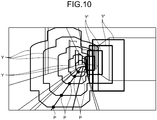
- FIG. 10 is a diagram illustrating an example of the enlarged monitoring region for the railway vehicle according to the second embodiment.
- the monitoring area recognizing unit 901 determines that the region in which the monitoring region is set is in the predetermined section, the monitoring area recognizing unit 901 sets the construction gauge cross-sections Y and surrounding regions Y' surrounding the construction gauge cross-sections Y for the set positions P. Then, the monitoring area recognizing unit 901 sets, as the monitoring region, a tunnel-shaped region having cross-sections that are the construction gauge cross-sections Y calculated for the different positions P and the surrounding regions Y' calculated for the different positions P.
- the example in which the construction gauge cross-sections Y and the surrounding regions Y' are set in the color image is described. However, also in the case where the loading gauge cross-sections X and surrounding regions are set in the color image, the monitoring region is set in the same manner.
- the railway vehicle RV of the second embodiment because it is possible to detect, as an obstacle, an object that can be an obstacle in a region around the loading gauge or the construction gauge, a state around the railway vehicle RV can be recognized. Consequently, it is possible to reduce the risk that the object enters the loading gauge or the construction gauge after the railway vehicle RV approaches a railway crossing gate, a station platform, or the like and is bumped by the railway vehicle RV.
- an obstacle that hinders the traveling of the railway vehicle RV can be detected with high accuracy.
- a computer program to be executed by the obstacle detection device 20, 90 according to the present embodiment is provided by being embedded in a ROM or the like, but may be provided by being recorded as a file in an installable format or an executable format in a computer-readable recording medium.
- the computer-readable recording medium is a CD-ROM, a flexible disk (FD), a CD-R, a digital versatile disk (DVD), or the like.
- the computer program to be executed by the obstacle detection device 20, 90 according to the present embodiment may be stored in a computer connected to a network such as the Internet and may be downloaded and provided via the Internet.
- the computer program to be executed by the obstacle detection device 20, 90 according to the present embodiment may be provided or distributed via the network such as the Internet.
- the computer program to be executed by the obstacle detection device 20, 90 has a module configuration including the foregoing units (image acquiring unit 201, rail recognizing unit 202, monitoring area recognizing unit 203, 901, candidate obstacle recognizing unit 204, obstacle determining unit 205, and result output unit 206).
- the CPU as actual hardware reads the computer program from the foregoing ROM and executes the computer program, thereby causing the foregoing units to be loaded into the main storage so that the image acquiring unit 201, the rail recognizing unit 202, the monitoring area recognizing unit 203, 901, the candidate obstacle recognizing unit 204, the obstacle determining unit 205, and the result output unit 206 can be generated on the main storage.
Landscapes
- Engineering & Computer Science (AREA)
- Physics & Mathematics (AREA)
- General Physics & Mathematics (AREA)
- Theoretical Computer Science (AREA)
- Multimedia (AREA)
- Quality & Reliability (AREA)
- Computer Vision & Pattern Recognition (AREA)
- Mechanical Engineering (AREA)
- Train Traffic Observation, Control, And Security (AREA)
- Image Analysis (AREA)
Abstract
Description
- Embodiments of the present invention relate to an obstacle detection device.
- In the operation of railway vehicles such as railway trains and electric trains, it is necessary to confirm whether an obstacle exists on a route so as to secure the safety of the railway vehicles. In a section in which an obstacle is likely to exist on the route of the railway vehicles due to fall of a traveler or baggage off a station platform, stuck of a car or bicycle at a railway crossing, or the like, a station platform fence for preventing the penetration of an obstacle, a railway crossing gate for preventing the penetration of an obstacle, a station platform fall detection device such as a pressure-sensitive mat for detecting the presence of an obstacle or an image recognition device for recognizing an image of an obstacle, an obstacle detection device of an optical type, a loop coil type, or the like for detecting the presence of an obstacle at a railway crossing, or the like is installed in some cases. In addition, in the section in which the obstacle is likely to exist on the route of the railway vehicles, an emergency stop alarm button for notifying the occurrence of a train or station emergency or the like is set in some cases.
- However, the foregoing equipment is installed in only sections in which an obstacle is likely to exist, in the route of railway vehicles, and it is difficult to cover the entire route of the railway vehicles. In addition, because, to detect an obstacle, ground equipment and on-vehicle equipment are required to coordinate with each other when using the foregoing equipment, there is a concern that systems are made more complex and are increased in size. Therefore, a system for detecting an obstacle exists has been developed. In the system, images in the traveling direction of a railway vehicle continuously captured by an imaging unit, mounted on the railway vehicle, is used to detect the obstacle.
-
- Patent Literature 1: Japanese Patent No.
5161673 - Patent Literature 2: Japanese Patent Application Laid-open No.
2016-052849 - Patent Literature 3: Japanese Patent No.
3888055 - Patent Literature 4: Japanese Patent Application Laid-open No.
2016-000598 - If an obstacle cannot be detected by a driver or the foregoing equipment before a distance between a railway vehicle and the obstacle becomes shorter than a total distance of an idling distance and a braking distance, it might be difficult to avoid a collision against the obstacle. The idling distance is a distance that the railway vehicle travels from a time the driver or the foregoing equipment recognizes the obstacle to a time braking is applied, and the braking distance is a distance that the railway vehicle travels from the time the braking is applied to a time the railway vehicle stops. In addition, compared with a car's collision avoidance system, the railway vehicle has a different feature that the railway vehicle cannot avoid an obstacle by steering due to restrictions such as a long braking distance and traveling on a rail. Therefore, the railway vehicle is requested to detect an obstacle present on a rail enough far away from the obstacle with high accuracy.
- An obstacle detection device according to an embodiment includes an acquiring unit, a rail detector, a monitoring region setting unit, an obstacle detector, and an output unit. The acquiring unit acquires a visible light image obtained by imaging in a traveling direction of a railway vehicle by an imaging unit included in the railway vehicle and a distance image that allows a distance to an object existing in an imaging range of the imaging unit to be identifiable. The rail detector detects, from the visible light image, a rail on which the railway vehicle travels. The monitoring region setting unit uses the rail as a standard to set, in the visible light image, a three-dimensional monitoring region defined by a loading gauge of the railway vehicle or a construction gauge. The obstacle detector detects an obstacle that exists in the monitoring region and hinders the traveling of the railway vehicle, based on range information that allows a distance range to the monitoring region based on the visible light image to be identifiable and the distance image. The output unit that outputs a result of detecting the obstacle.
-
-
FIG. 1 is a diagram illustrating an example of a schematic configuration of a railway vehicle according to a first embodiment. -
FIG. 2 is a block diagram illustrating an example of a functional configuration of an obstacle detection device included in the railway vehicle according to the first embodiment. -
FIG. 3 is a diagram illustrating an example of a monitoring region set for the railway vehicle according to the first embodiment. -
FIG. 4 is a diagram illustrating an example of the monitoring region set for the railway vehicle according to the first embodiment. -
FIG. 5 is a flowchart indicating an example of the flow of a process of detecting an obstacle in the railway vehicle according to the first embodiment. -
FIG. 6 is a schematic diagram illustrating an example of a method for setting a monitoring region in the railway vehicle according to the first embodiment. -
FIG. 7 is a diagram illustrating an example of a process of setting a standard plane for the railway vehicle according to the first embodiment. -
FIG. 8 is a diagram illustrating an example of a process of setting a monitoring region for a railway vehicle according to a modification. -
FIG. 9 is a diagram illustrating an example of a functional configuration of an obstacle detection device included in a railway vehicle according to a second embodiment. -
FIG. 10 is a diagram illustrating an example of an enlarged monitoring region for the railway vehicle according to the second embodiment. - Hereinafter, a railway vehicle including an obstacle detection device according to each embodiment is described with reference to the accompanying drawings.
-
FIG. 1 is a diagram illustrating an example of a schematic configuration of a railway vehicle according to a first embodiment. As illustrated inFIG. 1 , the railway vehicle RV according to the present embodiment includes asensor 10, anobstacle detection device 20, astorage 30, and adisplay 40. Thesensor 10 is an example of an imaging unit that can capture an image in a traveling direction of the railway vehicle RV. In the present embodiment, thesensor 10 can capture an image in an imaging range including a rail R existing in the traveling direction of the railway vehicle RV. Theobstacle detection device 20 is just an example for detecting an obstacle that hinders the traveling of the railway vehicle RV. Thestorage 30 stores a result of detecting an obstacle by theobstacle detection device 20. Thedisplay 40 displays an image obtained by imaging in the traveling direction of the railway vehicle RV by thesensor 10 and various types of information such as a result of detecting an obstacle by theobstacle detection device 20. -
FIG. 2 is a block diagram illustrating an example of a functional configuration of the obstacle detection device included in the railway vehicle according to the first embodiment. As illustrated inFIG. 2 , theobstacle detection device 20 includes animage acquiring unit 201, arail recognizing unit 202, a monitoringarea recognizing unit 203, a candidateobstacle recognizing unit 204, anobstacle determining unit 205, aresult output unit 206, and a storage 207. In the present embodiment, a part of or all of theimage acquiring unit 201, therail recognizing unit 202, the monitoringarea recognizing unit 203, the candidateobstacle recognizing unit 204, theobstacle determining unit 205, and theresult output unit 206 are achieved by causing a processor such as a central processing unit (CPU) included in the railway vehicle RV to execute software stored in the storage 207. - In addition, the part of or all of the
image acquiring unit 201, therail recognizing unit 202, the monitoringarea recognizing unit 203, the candidateobstacle recognizing unit 204, theobstacle determining unit 205, and theresult output unit 206 may be achieved by hardware that is a circuit board such as large scale integration (LSI), an application specific integrated circuit (ASIC), or a field programmable gate array (FPGA). Alternatively, theimage acquiring unit 201, therail recognizing unit 202, the monitoringarea recognizing unit 203, the candidateobstacle recognizing unit 204, theobstacle determining unit 205, and theresult output unit 206 may be achieved by causing the software executed by the processor and the hardware to collaborate with each other. - The storage 207 includes a nonvolatile storage medium such as a read only memory (ROM), a flash memory, a hard disk drive (HDD), or an SD card, and a volatile storage medium such as a random access memory (RAM) or a register. The storage 207 stores various types of information such as a computer program to be executed by the processor included in the railway vehicle RV.
- The
image acquiring unit 201 is an example of an acquiring unit that acquires a visible light image (hereinafter referred to as color image) obtained by imaging in the traveling direction of the railway vehicle RV by thesensor 10 and a distance image for identifying a distance to an object existing in the imaging range of thesensor 10. In the present embodiment, theimage acquiring unit 201 acquires, as the color image, any one of a plurality of images obtained by imaging in the traveling direction of the railway vehicle RV by a plurality of imaging units included in thesensor 10 from different points of view. - In addition, the
image acquiring unit 201 acquires the images as the distance image. In the present embodiment, theimage acquiring unit 201 converts the images obtained by the imaging by the imaging units included in thesensor 10 into gray-scaled images (hereinafter referred to as grayscale images). Then, theimage acquiring unit 201 geometrically converts the grayscale images into images (hereinafter referred to as parallel coordinate images) obtained when optical axes of the imaging units are virtually parallel to each other. Then, theimage acquiring unit 201 uses, in accordance with the principles of parallel stereo vision, one of the parallel coordinate images and the other of the parallel coordinate images to acquire the distance image for identifying the distance to the object existing in the imaging range of the imaging units included in thesensor 10. - The
rail recognizing unit 202 functions as an example of a rail detector that detects the rail R that is in the color image and on which the railway vehicle RV travels. In the present embodiment, therail recognizing unit 202 converts each of the grayscale images converted from the color images obtained by the imaging by thesensor 10 into an image (hereinafter referred to as edge-highlighted image) with edges highlighted. Then, therail recognizing unit 202 generates pixel groups by grouping certain pixels that are in the edge-highlighted image and have certain edge intensities larger than a predetermined edge intensity and pixels that are in pixels around the certain pixels and have edge intensities equal to or nearly equal to the certain edge intensities. Then, therail recognizing unit 202 extracts, from the generated pixel groups, pixel groups forming continuous lines extending in the traveling direction of the railway vehicle RV. Then, therail recognizing unit 202 detects, from among the extracted pixel groups, pixel groups satisfying a predetermined evaluation condition as the rail R on which the railway vehicle RV travels. The evaluation condition is that pixel groups are determined to be the rail R, for example, the pixel groups having edge intensities determined to be the rail R. - The monitoring
area recognizing unit 203 functions as an example of a monitoring region setting unit that sets a three-dimensional monitoring region in the color image using the rail R detected by therail recognizing unit 202 as a standard. The monitoring region is a three-dimensional region defined by a loading gauge of the railway vehicle RV or a construction gauge in the color image. In addition, the monitoringarea recognizing unit 203 calculates, based on the color image, range information for identifying a range that is a distance range from thesensor 10 to the monitoring region. -
FIGS. 3 and4 are diagrams illustrating examples of the monitoring region set for the railway vehicle according to the first embodiment. As illustrated inFIG. 3 , the monitoringarea recognizing unit 203 calculates loading gauge cross-sections X and distances to the loading gauge cross-sections X for arbitrary positions P on the detected rail R based on installation conditions of thesensor 10 and restrictions including a condition that a width of the rail R detected by therail recognizing unit 202 is constant. Each of the loading gauge cross-sections X is a cross-section of the loading gauge in a direction perpendicular to the traveling direction of the railway vehicle RV. The monitoringarea recognizing unit 203 sets, as the monitoring region, a tunnel-shaped region with cross-sections that are the loading gauge cross-sections X calculated for the different positions P on the rail R in the traveling direction of the railway vehicle RV. In addition, the monitoringarea recognizing unit 203 calculates, as range information, a range that is a range (set) of distances to the loading gauge cross-sections X calculated for the positions P. - In addition, as illustrated in
FIG. 4 , the monitoringarea recognizing unit 203 calculates construction cross-sections Y and distances to the construction gauge cross-sections Y for arbitrary positions P on the detected rail R based on the installation conditions of thesensor 10 and restrictions including the condition that the width of the rail R detected by therail recognizing unit 202 is constant. Each of the construction gauge cross-sections Y is a cross-section of the construction gauge in the direction perpendicular to the traveling direction of the railway vehicle RV. The monitoringarea recognizing unit 203 sets, as the monitoring region, a tunnel-shaped region with cross-sections that are the construction gauge cross-sections Y calculated for the different positions P on the rail R in the traveling direction of the railway vehicle RV. In addition, the monitoringarea recognizing unit 203 calculates, as range information, a range that is a range (set) of distances to the construction gauge cross-sections Y calculated for the positions P. - Returning to
FIG. 2 , the candidateobstacle recognizing unit 204 extracts, as candidates (hereinafter referred to as candidate obstacles) of an obstacle, objects in the monitoring region based on the distance image and the range information. In the present embodiment, the candidateobstacle recognizing unit 204 extracts, as a three-dimensional candidate obstacle existing in the monitoring region, a similar region obtained by grouping pixels from among pixels within the distance image and indicating distances matching the distances identified by the range information. - The
obstacle determining unit 205 detects an obstacle from the candidate obstacles based on at least one of sizes of the candidate obstacles extracted by the candidateobstacle recognizing unit 204 and moving vectors of the candidate obstacles. Therefore, because it is possible to detect, as an obstacle, an object that is likely to be an obstacle from among objects existing in the monitoring region, the accuracy of detecting the obstacle can be improved. In the present embodiment, theobstacle determining unit 205 detects, as an obstacle, a candidate obstacle that is among the candidate obstacles and has a size equal to or larger than a size set in advance. In addition, theobstacle determining unit 205 detects, as an obstacle, a candidate obstacle that is among the candidate obstacles and has a moving vector pointing toward the rail R. In addition, theobstacle determining unit 205 may detect, as an obstacle, a candidate obstacle that is among the candidate obstacles and has a size equal to or larger than the size set in advance and a moving vector pointing toward the rail R. - In the present embodiment, the candidate
obstacle recognizing unit 204 and theobstacle determining unit 205 collaborate with each other to function as an example of an obstacle detector that detects, based on the distance image and the range information, an obstacle that is in the monitoring region and hinders the traveling of the railway vehicle RV. Therefore, when the color image obtained by the imaging in the traveling direction of the railway vehicle RV is used to detect an obstacle that hinders the traveling of the railway vehicle RV, it is possible to dynamically and approximately set the monitoring region from which the obstacle is detected in the color image and to detect the obstacle, and thus the obstacle that hinders the traveling of the railway vehicle RV can be detected with high accuracy. - The
result output unit 206 functions as an example of an output unit that outputs a result of detecting an obstacle by the candidateobstacle recognizing unit 204 and theobstacle determining unit 205. In the present embodiment, when an obstacle is detected by theobstacle determining unit 205, theresult output unit 206 causes thedisplay 40 to display the color image and information indicating that the obstacle has been detected. In addition, theresult output unit 206 stores the result of detecting the obstacle in thestorage 30. - Next, an example of a process of detecting an obstacle by the railway vehicle according to the present embodiment is described with reference to
FIG. 5. FIG. 5 is a flowchart indicating the example of the process of detecting an obstacle in the railway vehicle according to the first embodiment. - The
image acquiring unit 201 acquires the color image and the distance image from the sensor 10 (in step S501). Thesensor 10 is an optical sensor that can simultaneously output the color image and the distance image and is an optical sensor of pattern projection type, photogrammetry type, or time-of-flight type. In addition, when thesensor 10 includes two imaging units (left and right imaging units) separated from each other in a vehicle width direction of the railway vehicle RV, theimage acquiring unit 201 may acquire, as the distance image, two color images obtained by imaging by the two imaging units. - Upon acquiring the two color images, as the distance image, the
image acquiring unit 201 converts the two color images into grayscale images (in step S502). The present embodiment describes an example in which theimage acquiring unit 201 converts the two color images into the grayscale images to reduce a calculation amount necessary to detect an obstacle and uses the grayscale images to detect the obstacle. The obstacle, however, can be detected using the color images as they are. - Next, the
image acquiring unit 201 geometrically transforms the two grayscale images into parallel coordinate images (in step S503). A general camera lens has a distortion in a radial direction and a distortion in a circumferential direction. Therefore, a coefficient and/or a table that are necessary to correct distortions of images obtained by imaging by thesensor 10 is stored, as image conversion information, in the storage 207. Then, theimage acquiring unit 201 can use the image conversion information stored in the storage 207 to correct distortions of the grayscale images based on aberration of lenses or the like. In addition, an internal parameter of thesensor 10 and an external parameter based on relative positional relations may be calculated by calibration, and the external parameter may be stored as the image conversion information in the storage 207. - Next, the
image acquiring unit 201 uses one of the parallel coordinate images as a standard image and the other of the parallel coordinate images as a reference image to calculate disparity between the standard image and the reference image as the distance image (in step S504). According to a geometrical restrictions such as epipolar geometry, a corresponding pixel in the reference image, corresponding to a target pixel in the standard image, is calculated by searching only an epipolar line at the same height position as that of the target pixel of the standard image. Therefore, the corresponding pixel can be searched with a small calculation amount and with high accuracy.
The search of the corresponding pixel is executed by template matching, global matching, semi-global matching, or the like. In the template matching, the corresponding pixel is searched from each of small regions that are some regions within the reference image. In the global matching, the optimal corresponding pixel (solution) is searched from the entire reference image. In the semi-global matching, the optimal corresponding pixel is searched from pixels around the target pixel in the reference image. However, when the real time search is requested for the corresponding pixel, the corresponding pixel is searched by the template matching in many cases. - After the calculation of the corresponding pixel, the
image acquiring unit 201 calculates the disparity between the target pixel of the standard image and the corresponding pixel of the reference image. In the present embodiment, theimage acquiring unit 201 calculates the corresponding pixel of the reference image while shifting the target pixel of the standard image one by one. Therefore, when the reference image is a digital image, coordinates of the corresponding pixel are represented by integers. Therefore, when the coordinates of the corresponding pixel are estimated with decimal precision, a subpixel estimation method is used. In the subpixel estimation method, when an evaluation function to be used to search for the corresponding pixel is a primary function such as the sum of absolute difference (SAD), equiangular linear fitting is used. In the subpixel estimation method, when the evaluation function to be used to search for the corresponding pixel is a secondary function such as the sum of squared difference (SSD), parabola fitting is used. - When it is not necessary to calculate the disparity with decimal precision or when a processing time for acquiring the disparity is to be reduced, the disparity may be calculated without using the subpixel estimation method. In addition, when an evaluation value of the coordinates of the corresponding pixel that is based on the evaluation function used in the subpixel estimation method is larger than a predetermined threshold, and a difference between characteristic amounts (for example, changes in gradations) of the target pixel and the corresponding pixel is small, the calculated disparity may be invalidated.
- By executing the foregoing processes, the
image acquiring unit 201 calculates disparity between pixels of the reference image and all pixels of the standard image or pixels in a valid region of a part of the standard image. Then, theimage acquiring unit 201 uses the following Equation (1) to calculate, as the distance image, a distance Z to an object indicated by pixels of the standard image. In the following Equation (1), f indicates a focal distance of the two imaging units included in thesensor 10, B indicates a distance between the two imaging units included in thesensor 10, and D indicates disparity D between a pixel of the standard image and a pixel of the reference image.
- Next, the
rail recognizing unit 202 detects candidate rails that are candidates of the rail R on which the railway vehicle RV travels (in step S505). In the present embodiment, therail recognizing unit 202 converts the standard image into an edge-highlighted image. Next, therail recognizing unit 202 detects, as the candidate rails, pixel groups forming continuous lines extending in the traveling direction of the railway vehicle RV from pixel groups obtained by grouping certain pixels having certain edge intensities larger than the predetermined edge intensity and pixels existing around the certain pixels and having edge intensities equal to or nearly equal to the certain edge intensities in the edge-highlighted image. Then, therail recognizing unit 202 detects, as the rail R, a candidate rail satisfying the evaluation condition set in advance from the detected candidate rails (in step S506). - The monitoring
area recognizing unit 203 uses the rail R detected by therail recognizing unit 202 as a standard and sets a three-dimensional monitoring region in the standard image (in step S507). -
FIG. 6 is a schematic diagram illustrating an example of a method for setting the monitoring region in the railway vehicle according to the first embodiment. As illustrated inFIG. 6 , the monitoringarea recognizing unit 203 sets, for any arbitrary position P on the rail R detected by therail recognizing unit 202, a horizontal line connecting left and right segments of the rail R and existing at the position P. The line has a length of L pixels in the standard image. Then, when pitch angles, yaw angles, and roll angles of the imaging units included in thesensor 10 are all 0°, and the rail R on which the railway vehicle RV travels has a narrow gauge, resolution per pixel in the horizontal direction is 1067/L millimeters. - Alternatively, the monitoring
area recognizing unit 203 uses the distance image to acquire disparity between a target pixel at the position P and a corresponding pixel or a distance to the position P. Then, the monitoringarea recognizing unit 203 calculates resolution per pixel based on the disparity or the distance in advance and identifies resolution per pixel based on the acquired disparity or the acquired distance. Then, the monitoringarea recognizing unit 203 may treat the identified resolution per pixel as resolution per pixel in the horizontal direction at the position P. When aspect ratios of imaging elements of thesensor 10 are 1:1, resolution per pixel in a direction (or vertical direction) perpendicular to the line is the same as the resolution per pixel in the horizontal direction. - Next, as illustrated in
FIG. 6 , the monitoringarea recognizing unit 203 sets a loading gauge cross-section X for each of the positions P within the standard image based on dimensions (for example, a width: 3800 mm, a height: 4300 mm) of the loading gauge in the actual space and the resolution per pixel in the standard image. In the present embodiment, the monitoringarea recognizing unit 203 sets a region imitating a cross-section of the loading gauge as the loading gauge cross-section X, but is not limited to this as long as a region that allows the loading gauge to be identifiable is set as the loading gauge cross-section X. For example, the monitoringarea recognizing unit 203 may set, as the loading gauge cross-section X, a region of a predetermined shape, such as a rectangle approximating the cross-section of the loading gauge. In addition, although an example in which the loading gauge cross-section X is set in the standard image is described, the same applies to the case where a construction gauge cross-section Y is set in the standard image. After that, the monitoringarea recognizing unit 203 sets a tunnel-shaped monitoring region in the standard image by repeatedly setting the loading gauge cross-section X for each of the positions P while moving the positions P within the standard image in the traveling direction of the railway vehicle RV. - In addition, the monitoring
area recognizing unit 203 calculates, for each of the positions P, a distance to the position P or the disparity between a target pixel at the position P and a corresponding pixel based on the resolution per pixel in the standard image, the number of pixels in a range from a lower end (or an end on the near side in the imaging range of the sensor 10) of the standard image to the position P, and the like. Then, the monitoringarea recognizing unit 203 treats, as range information, a range of distances calculated for the positions P or a range of disparity calculated for the positions P. In addition, the monitoringarea recognizing unit 203 stores the range information, as monitoring area information, in the storage 207. - Returning to
FIG. 5 , the candidateobstacle recognizing unit 204 sets, in the standard image, a standard plane in contact with an upper surface of the rail R detected by the rail recognizing unit 202 (in step S508). Therefore, an object that exists under the rail R and is unlikely to be an obstacle is not detected as a candidate obstacle, and thus a processing load caused by the process of detecting an obstacle can be reduced. -
FIG. 7 is a diagram illustrating an example of a process of setting the standard plane for the railway vehicle according to the first embodiment. As illustrated inFIG. 7 , the candidateobstacle recognizing unit 204 sets, as standard planes P1 and P2, approximate flat or curved planes along a part of the upper surface of the rail R recognized by therail recognizing unit 202 and the part of the upper surface is in an area close to thesensor 10 or an area with similar disparity. - Returning to
FIG. 5 , next, the candidateobstacle recognizing unit 204 extracts, as candidate obstacles, objects in the monitoring region of the standard image based on the distance image indicating the disparity (or distance) between the standard image and the reference image, and the range information (in step S509). Specifically, as candidate obstacles, the candidateobstacle recognizing unit 204 extracts objects, from the objects in the standard image, having a disparity between the standard image and the reference image or a distance within the range indicated in the range information. - Among the objects in the monitoring region, any object partially included in the monitoring region may not be detected as an obstacle for such a reason that the size of the object is smaller than a predetermined size, or the like. Therefore, in the present embodiment, the candidate
obstacle recognizing unit 204 extracts, as a candidate obstacle, an object existing above the standard plane. Specifically, among the objects in the monitoring region of the standard image, the candidateobstacle recognizing unit 204 extracts, as a candidate obstacle, an object residing on the near side with respect to the standard plane, or an object closer thesensor 10 than the standard plane (or an object having larger disparity than disparity of the standards plane). - The
obstacle determining unit 205 detects an obstacle from among the candidate obstacles based on at least one of sizes of the candidate obstacles and moving vectors of the candidate obstacles (in step S510). In the present embodiment, theobstacle determining unit 205 discards, as noise or disturbance, any candidate obstacle, among the candidate obstacles, having an aspect ratio of a circumscribed rectangle that is extremely biased in the standard image. In addition, theobstacle determining unit 205 calculates a moving vector of a candidate obstacle between standard images of two or more frames among the candidate obstacles. When the moving vector points from the lower side to the upper side, theobstacle determining unit 205 discards the obstacle as disturbance such as a bird or smoke. Then, theobstacle determining unit 205 detects, as an obstacle, a candidate obstacle that is among the candidate obstacles and remains without being discarded and has the center of gravity the position of which is in the monitoring region. - Then, the
result output unit 206 outputs, to thedisplay 40, a result of detecting the obstacle by theobstacle determining unit 205 and causes thedisplay 40 to display the result of detecting the obstacle (in step S511). In the present embodiment, theresult output unit 206 causes thedisplay 40 to display, as the result of detecting the obstacle, the fact that the obstacle has been detected by theobstacle determining unit 205, a distance to the detected obstacle, and the like. In addition, theresult output unit 206 outputs audio notifying the result of detecting the obstacle and outputs the result of detecting the obstacle to a vehicle control device for controlling the traveling of the railway vehicle RV. Furthermore, theresult output unit 206 stores detection result information indicating the result of detecting the obstacle in the storage 207. Furthermore, theresult output unit 206 can store the detection result information in an external storage. Therefore, even in an offline state where an external device cannot communicate with theobstacle detection device 20 of the railway vehicle RV, the external device can use the detection result information stored in the external storage to analyze the result of detecting the obstacle. - After that, the
image acquiring unit 201 determines whether the termination of the process of detecting an obstacle is instructed (in step S512). When the termination of the process of detecting an obstacle is instructed (Yes at step S512), theimage acquiring unit 201 does not acquire a new color image and a distance image and terminates the process of detecting an obstacle. In contrast, when the termination of the process of detecting an obstacle has not been instructed (No at step S512), theimage acquiring unit 201 returns to step S501 and acquires the new color image and the distance image. - According to the railway vehicle RV of the first embodiment, when the color image obtained by the imaging in the traveling direction of the railway vehicle RV is used to detect an obstacle that hinders the traveling of the railway vehicle RV, it is possible to dynamically and appropriately set the monitoring region from which the obstacle is detected in the color image and detect the obstacle. Therefore, the obstacle that hinders the traveling of the railway vehicle RV can be detected with high accuracy.
- A modification is an example in which when a plurality of rails are detected from a color image, a monitoring region is set for each of the rails using the rails as standards. The following describes different features from the first embodiment.
-
FIG. 8 is a diagram illustrating an example of a process of setting a monitoring region for a railway vehicle according to the modification. As illustrated inFIG. 8 , when a plurality of rails R1 and R2 are detected by therail recognizing unit 202, the monitoringarea recognizing unit 203 sets monitoring regions A1 and A2 for the rails R1 and R2. - However, when the rail R1 on which the railway vehicle RV travels is identifiable by the
rail recognizing unit 202 from the rails R1 and R2, the monitoringarea recognizing unit 203 may set a monitoring region (for example, the monitoring region A1) only for the rail R1. Therefore, when the rails R are detected by therail recognizing unit 202, it is sufficient if a monitoring region is set for any one of the rails R, and thus a processing load caused by the process of setting a monitoring region can be reduced. For example, the monitoringarea recognizing unit 203 recognizes, from an image, the orientation of the rail R at a point portion on the rail R on which the railway vehicle RV travels and current indication of a traffic light. Then, the monitoringarea recognizing unit 203 identifies, based on the results of the recognition, the rail R on which the railway vehicle RV travels. Alternatively, the monitoringarea recognizing unit 203 may identify, based on a service schedule of the railway vehicle RV, the rail R on which the railway vehicle RV travels. - A present embodiment is an example in which a monitoring region is enlarged in a predetermined section in a traveling section in which a railway vehicle travels. In the following description, a description of the same configurations as those described in the first embodiment is omitted.
-
FIG. 9 is a diagram illustrating an example of a functional configuration of a traveling obstacle detection device included in a railway vehicle according to the second embodiment. As illustrated inFIG. 9 , in the present embodiment, the railway vehicle RV includes thesensor 10, anobstacle detection device 90, thedisplay 40, thestorage 30, and aposition measuring device 60. Theposition measuring device 60 is a position measuring unit that measures a traveling position of the railway vehicle RV. For theposition measuring device 60, a tachometer generator (TG) and a global navigation satellite system (GNSS) are used. Theobstacle detection device 90 includes theimage acquiring unit 201, therail recognizing unit 202, a monitoringarea recognizing unit 901, the candidateobstacle recognizing unit 204, theobstacle determining unit 205, theresult output unit 206, and astorage 903. - For example, objects existing in not only a loading gauge and a construction gauge but also regions around the loading gauge and the construction gauge may be obstacles at a railway crossing gate where pedestrians, bicycles, vehicles, and the like come and go on a rail and may hinder the traveling of the railway vehicle RV, a station platform from which a passenger, baggage, or the like falls and may hinder the traveling of the railway vehicle RV on the rail R, and the like.
- Therefore, the monitoring
area recognizing unit 901 enlarges a monitoring region within a standard image so that a region around the loading gauge or the construction gauge can be included in the monitoring region in the predetermined section in the traveling section of the railway vehicle RV. The predetermined section is a section that is preset and can be an obstacle in a region around the loading gauge or the construction gauge. Therefore, because it is possible to detect, as an obstacle, an object that can be an obstacle in the region around the loading gauge or the construction gauge, a state around the railway vehicle RV can be recognized. Consequently, it is possible to reduce the risk that an object enters the loading gauge or the construction gauge after the railway vehicle RV approaches a railway crossing gate, a station platform, or the like, and is bumped by the railway vehicle RV. - Therefore, in the present embodiment, it is necessary that the monitoring
area recognizing unit 901 determine whether the monitoring region in the standard image is set in the predetermined section. For example, the monitoringarea recognizing unit 901 determines, based on a color image, whether a region in which the monitoring region is set is in the predetermined section. Specifically, when a symbol such as a station platform, a railway crossing gate, a sign, or a traffic light exists in the predetermined section, the monitoringarea recognizing unit 901 detects the symbol from the color image by a pattern recognition technique or the like, thereby identifying a start point of the predetermined section and an end point of the predetermined section. Then, the monitoringarea recognizing unit 901 enlarges the monitoring region between the identified start point and the identified end point. - Alternatively, the monitoring
area recognizing unit 901 may detect, as the symbol, a structural object (for example, an end of a station platform or a structure specific to a railway crossing gate) around the predetermined section and identify the start and end points of the predetermined section. Alternatively, a dedicated sign from which the start and end points of the predetermined section is identifiable may be installed at a position that is on the ground side and can be imaged by thesensor 10. Then, when the monitoringarea recognizing unit 901 recognizes the dedicated sign from the color image by the pattern recognition technique, the monitoringarea recognizing unit 901 may determine that the region in which the monitoring region is set is the predetermined section, and enlarge the monitoring region. - In addition, a communication device (example of an external device) that can execute wireless communication to transmit, to the railway vehicle RV traveling near the predetermined section, positional information indicating a position (for example, the start and end points of the predetermined section) of the predetermined section may be installed on the ground side. In this case, the monitoring
area recognizing unit 901 receives the positional information from the communication device. Then, the monitoringarea recognizing unit 901 enlarges the monitoring region at the position indicated in the received positional information. The communication device is a transponder ground coil, a radio frequency identifier (RFID) tag, or the like. However, because it is necessary to detect an obstacle 200 to 300 meters before the obstacle, it is necessary that the communication device be installed several hundreds of meters before the predetermined section and transmit the positional information to the railway vehicle RV located several hundreds of meters away from the communication device. - In addition, when the railway vehicle RV includes the
position measuring device 60 and thestorage 903 stores the positional information (for example, enlarged monitoring area information indicating the start and end points of the predetermined section) of the predetermined section, the monitoringarea recognizing unit 901 may enlarge the monitoring region in the case where a traveling position measured by theposition measuring device 60 is between the start and end points indicated in the enlarged monitoring area information stored in thestorage 903. The enlarged monitoring area information is information representing the start and end positions of the predetermined section in a unit system (for example, kilometers, or longitude and latitude) or the like. -
FIG. 10 is a diagram illustrating an example of the enlarged monitoring region for the railway vehicle according to the second embodiment. As illustrated inFIG. 10 , when the monitoringarea recognizing unit 901 determines that the region in which the monitoring region is set is in the predetermined section, the monitoringarea recognizing unit 901 sets the construction gauge cross-sections Y and surrounding regions Y' surrounding the construction gauge cross-sections Y for the set positions P. Then, the monitoringarea recognizing unit 901 sets, as the monitoring region, a tunnel-shaped region having cross-sections that are the construction gauge cross-sections Y calculated for the different positions P and the surrounding regions Y' calculated for the different positions P. The example in which the construction gauge cross-sections Y and the surrounding regions Y' are set in the color image is described. However, also in the case where the loading gauge cross-sections X and surrounding regions are set in the color image, the monitoring region is set in the same manner. - According to the railway vehicle RV of the second embodiment, because it is possible to detect, as an obstacle, an object that can be an obstacle in a region around the loading gauge or the construction gauge, a state around the railway vehicle RV can be recognized. Consequently, it is possible to reduce the risk that the object enters the loading gauge or the construction gauge after the railway vehicle RV approaches a railway crossing gate, a station platform, or the like and is bumped by the railway vehicle RV.
- As described above, according to the first and the second embodiments, an obstacle that hinders the traveling of the railway vehicle RV can be detected with high accuracy.
- A computer program to be executed by the
obstacle detection device - The computer program to be executed by the
obstacle detection device obstacle detection device - The computer program to be executed by the
obstacle detection device image acquiring unit 201,rail recognizing unit 202, monitoringarea recognizing unit obstacle recognizing unit 204,obstacle determining unit 205, and result output unit 206). The CPU as actual hardware reads the computer program from the foregoing ROM and executes the computer program, thereby causing the foregoing units to be loaded into the main storage so that theimage acquiring unit 201, therail recognizing unit 202, the monitoringarea recognizing unit obstacle recognizing unit 204, theobstacle determining unit 205, and theresult output unit 206 can be generated on the main storage. - Although the embodiments of the invention are described, these embodiments are presented as examples and are not intended to limit the scope of the invention. It is possible to implement the new embodiments in other various forms and conduct various omission, replacement, and changes without departing from the gist of the invention. The embodiments and the modifications thereof are included in the scope and gist of the invention and included in the scope of the invention described in the claims and the scope of equivalents thereof.
Claims (11)
- An obstacle detection device comprising:an acquiring unit that acquires a visible light image obtained by imaging in a traveling direction of a railway vehicle by an imaging unit included in the railway vehicle and a distance image that allows a distance to an object existing in an imaging range of the imaging unit to be identifiable;a rail detector that detects, from the visible light image, a rail on which the railway vehicle travels;a monitoring region setting unit that uses the rail as a standard to set, in the visible light image, a three-dimensional monitoring region defined by a loading gauge of the railway vehicle or a construction gauge;an obstacle detector that detects an obstacle that exists in the monitoring region and hinders the traveling of the railway vehicle, based on range information that allows a distance range to the monitoring region based on the visible light image to be identifiable and the distance image; andan output unit that outputs a result of detecting the obstacle.
- The obstacle detection device according to claim 1, further comprising:a candidate detector that detects, as candidates of the obstacle, objects existing in the monitoring region based on the distance image and the range information, whereinthe obstacle detector detects the obstacle from among the candidates of the obstacle based on at least one of sizes of the candidates of the obstacle and moving vectors of the candidates of the obstacle.
- The obstacle detection device according to claim 1 or 2, wherein
the acquiring unit acquires, as the visible light image, any one of a plurality of images obtained by imaging in the traveling direction of the railway vehicle by a plurality of the imaging units from different points of view and acquires the images as the distance image. - The obstacle detection device according to claim 3, wherein
the distance image indicates disparity between the images, and
the range information indicates a range of disparity of the monitoring region. - The obstacle detection device according to any one of claims 1 to 4, wherein
when a plurality of the rails are detected by the rail detector from the light visible image, the monitoring region setting unit sets the monitoring region for each of the rails. - The obstacle detection device according to any one of claims 1 to 4, wherein
when a plurality of the rails are detected by the rail detector from the light visible image, the monitoring region setting unit sets the monitoring region for only the rail that is among the rails and on which the railway vehicle travels. - The obstacle detection device according to claim 2, wherein
the candidate detector sets a standard plane in contact with an upper surface of the rail in the visible light image and detects, as a candidate of the obstacle, an object existing above the standard plane. - The obstacle detection device according to any one of claims 1 to 7, wherein
the monitoring region setting unit enlarges the monitoring region so that a region around the loading gauge of the railway vehicle or the construction gauge is included in the monitoring region in a predetermined section within a traveling section in which the railway vehicle travels. - The obstacle detection device according to claim 8, wherein
the monitoring region setting unit detects the predetermined section from the visible light image and enlarges the monitoring region in the predetermined section. - The obstacle detection device according to claim 8, wherein
the monitoring region setting unit receives, from an external device, positional information indicating a position of the predetermined section and enlarges the monitoring region at the position indicated in the positional information. - The obstacle detection device according to claim 8, further comprising:a position measuring unit that measures a traveling position of the railway vehicle; anda storage that stores positional information indicating the predetermined section, whereinthe monitoring region setting unit enlarges the monitoring region in the predetermined section based on the traveling position measured by the position measuring unit and the positional information stored in the storage.
Applications Claiming Priority (2)
| Application Number | Priority Date | Filing Date | Title |
|---|---|---|---|
| JP2017212847A JP7062407B2 (en) | 2017-11-02 | 2017-11-02 | Obstacle detection device |
| PCT/JP2018/040899 WO2019088267A1 (en) | 2017-11-02 | 2018-11-02 | Obstacle detecting device |
Publications (2)
| Publication Number | Publication Date |
|---|---|
| EP3705371A1 true EP3705371A1 (en) | 2020-09-09 |
| EP3705371A4 EP3705371A4 (en) | 2021-08-11 |
Family
ID=66332551
Family Applications (1)
| Application Number | Title | Priority Date | Filing Date |
|---|---|---|---|
| EP18872331.6A Withdrawn EP3705371A4 (en) | 2017-11-02 | 2018-11-02 | Obstacle detecting device |
Country Status (4)
| Country | Link |
|---|---|
| EP (1) | EP3705371A4 (en) |
| JP (1) | JP7062407B2 (en) |
| CN (1) | CN111295321A (en) |
| WO (1) | WO2019088267A1 (en) |
Cited By (6)
| Publication number | Priority date | Publication date | Assignee | Title |
|---|---|---|---|---|
| CN112857329A (en) * | 2021-02-02 | 2021-05-28 | 中国铁路设计集团有限公司 | Existing railway turnout center measuring method and system, storage medium and electronic equipment |
| EP4029758A1 (en) * | 2021-01-18 | 2022-07-20 | Siemens Mobility GmbH | Safety-critical on-board monitoring of the environment of a rail vehicle |
| WO2022268375A1 (en) * | 2021-06-23 | 2022-12-29 | Siemens Mobility GmbH | Obstacle detection in the track area on the basis of depth data |
| EP4181090A1 (en) * | 2021-11-12 | 2023-05-17 | Kabushiki Kaisha Toshiba | Information processing apparatus and program |
| EP4446195A1 (en) * | 2023-04-12 | 2024-10-16 | Siemens Mobility GmbH | Method for obstacle recognition for a track bound vehicle |
| EP4497653A1 (en) * | 2023-07-28 | 2025-01-29 | Kabushiki Kaisha Toshiba | Information processing method and device for estimating the three-dimensional position of a railroad track |
Families Citing this family (13)
| Publication number | Priority date | Publication date | Assignee | Title |
|---|---|---|---|---|
| JP7068068B2 (en) * | 2018-06-26 | 2022-05-16 | 株式会社東芝 | Detection area database creation device |
| JP7502025B2 (en) | 2019-12-23 | 2024-06-18 | 株式会社東芝 | Camera automatic inspection system |
| JPWO2021149211A1 (en) * | 2020-01-23 | 2021-07-29 | ||
| US11763570B2 (en) * | 2020-07-02 | 2023-09-19 | Alps Alpine Co., Ltd. | Obstacle detection device, obstacle detection method, and storage medium storing obstacle detection program |
| DE102020210821A1 (en) * | 2020-08-27 | 2022-03-03 | Siemens Mobility GmbH | Procedure for checking a structure gauge for a rail vehicle |
| JP7406477B2 (en) * | 2020-10-13 | 2023-12-27 | 株式会社日立製作所 | Obstacle detection system and obstacle detection method |
| CN112660171B (en) * | 2020-12-30 | 2024-02-20 | 北京市地铁运营有限公司地铁运营技术研发中心 | Safety protection system and method |
| JP7458344B2 (en) | 2021-04-15 | 2024-03-29 | 株式会社東芝 | Railway vehicle operation control device |
| JP7467397B2 (en) * | 2021-09-03 | 2024-04-15 | 株式会社日立製作所 | Obstacle Detection Device |
| JP7794591B2 (en) * | 2021-09-22 | 2026-01-06 | 日本信号株式会社 | Signal aspect identification system |
| CN116039718B (en) * | 2021-10-27 | 2025-11-04 | 比亚迪股份有限公司 | Train screening methods, screening controllers and train signaling systems |
| US20230391384A1 (en) * | 2022-04-12 | 2023-12-07 | Eric August HULLEMEYER | Automated operation of railroad trains |
| CN117495847B (en) * | 2023-12-27 | 2024-03-19 | 安徽蔚来智驾科技有限公司 | Intersection detection method, readable storage medium and intelligent device |
Family Cites Families (17)
| Publication number | Priority date | Publication date | Assignee | Title |
|---|---|---|---|---|
| JP3888055B2 (en) | 2000-12-26 | 2007-02-28 | 財団法人鉄道総合技術研究所 | Train forward anomaly detection device using optical flow |
| DE10141037C1 (en) * | 2001-08-20 | 2003-04-03 | Siemens Ag | Obstacle detection device |
| DE10260555A1 (en) * | 2002-12-21 | 2004-07-01 | Eads Radio Communication Systems Gmbh & Co.Kg | Obstacle warning system for track-guided vehicles |
| JP3977802B2 (en) * | 2003-12-16 | 2007-09-19 | 株式会社東芝 | Obstacle detection device, obstacle detection method, and obstacle detection program |
| JP2008257378A (en) * | 2007-04-03 | 2008-10-23 | Honda Motor Co Ltd | Object detection device |
| JP5161673B2 (en) | 2008-06-30 | 2013-03-13 | 株式会社神戸製鋼所 | Falling object detection device and falling object detection method |
| US8693725B2 (en) * | 2011-04-19 | 2014-04-08 | International Business Machines Corporation | Reliability in detecting rail crossing events |
| JP5811189B2 (en) * | 2011-12-28 | 2015-11-11 | トヨタ自動車株式会社 | Obstacle determination device |
| DK3027482T3 (en) * | 2013-07-31 | 2021-12-20 | Rail Vision Ltd | SYSTEM AND PROCEDURE FOR IDENTIFICATION AND AVOIDANCE OF PREVENTION |
| DE102014206473A1 (en) * | 2014-04-03 | 2015-10-08 | Bombardier Transportation Gmbh | Automatic assistance to a driver of a lane-bound vehicle, in particular a rail vehicle |
| JP6381981B2 (en) | 2014-06-12 | 2018-08-29 | 西日本旅客鉄道株式会社 | Track space obstacle detection system |
| US20160019429A1 (en) * | 2014-07-17 | 2016-01-21 | Tomoko Ishigaki | Image processing apparatus, solid object detection method, solid object detection program, and moving object control system |
| JP6209141B2 (en) | 2014-09-04 | 2017-10-04 | 公益財団法人鉄道総合技術研究所 | Obstacle detection apparatus and method |
| JP5947938B1 (en) * | 2015-03-06 | 2016-07-06 | ヤマハ発動機株式会社 | Obstacle detection device and moving body equipped with the same |
| JP6346868B2 (en) * | 2015-03-31 | 2018-06-20 | 公益財団法人鉄道総合技術研究所 | Stereo image processing method and apparatus |
| CN105346565B (en) * | 2015-09-29 | 2017-12-01 | 北京京天威科技发展有限公司 | Invade limit intelligent monitor system and monitoring center database |
| JP6524529B2 (en) * | 2015-10-27 | 2019-06-05 | 株式会社明電舎 | Building limit judging device |
-
2017
- 2017-11-02 JP JP2017212847A patent/JP7062407B2/en active Active
-
2018
- 2018-11-02 EP EP18872331.6A patent/EP3705371A4/en not_active Withdrawn
- 2018-11-02 CN CN201880071288.8A patent/CN111295321A/en active Pending
- 2018-11-02 WO PCT/JP2018/040899 patent/WO2019088267A1/en not_active Ceased
Cited By (6)
| Publication number | Priority date | Publication date | Assignee | Title |
|---|---|---|---|---|
| EP4029758A1 (en) * | 2021-01-18 | 2022-07-20 | Siemens Mobility GmbH | Safety-critical on-board monitoring of the environment of a rail vehicle |
| CN112857329A (en) * | 2021-02-02 | 2021-05-28 | 中国铁路设计集团有限公司 | Existing railway turnout center measuring method and system, storage medium and electronic equipment |
| WO2022268375A1 (en) * | 2021-06-23 | 2022-12-29 | Siemens Mobility GmbH | Obstacle detection in the track area on the basis of depth data |
| EP4181090A1 (en) * | 2021-11-12 | 2023-05-17 | Kabushiki Kaisha Toshiba | Information processing apparatus and program |
| EP4446195A1 (en) * | 2023-04-12 | 2024-10-16 | Siemens Mobility GmbH | Method for obstacle recognition for a track bound vehicle |
| EP4497653A1 (en) * | 2023-07-28 | 2025-01-29 | Kabushiki Kaisha Toshiba | Information processing method and device for estimating the three-dimensional position of a railroad track |
Also Published As
| Publication number | Publication date |
|---|---|
| JP2019084881A (en) | 2019-06-06 |
| EP3705371A4 (en) | 2021-08-11 |
| WO2019088267A1 (en) | 2019-05-09 |
| CN111295321A (en) | 2020-06-16 |
| JP7062407B2 (en) | 2022-05-06 |
Similar Documents
| Publication | Publication Date | Title |
|---|---|---|
| JP7062407B2 (en) | Obstacle detection device | |
| CN108692719B (en) | Object detection device | |
| US9651393B2 (en) | Driving support device, driving support method, and recording medium storing driving support program | |
| US8180561B2 (en) | Vehicle-installation obstacle detection apparatus | |
| CN101303735B (en) | Method for detecting moving objects in a blind spot region of a vehicle and blind spot detection device | |
| US11113543B2 (en) | Facility inspection system and facility inspection method | |
| US9389093B2 (en) | Traffic signal recognition apparatus | |
| US20170344844A1 (en) | Information processing apparatus and information processing method | |
| US10846546B2 (en) | Traffic signal recognition device | |
| US10672141B2 (en) | Device, method, system and computer-readable medium for determining collision target object rejection | |
| CN110431562B (en) | Image recognition device | |
| EP3057063A1 (en) | Object detection device and vehicle using same | |
| US11204610B2 (en) | Information processing apparatus, vehicle, and information processing method using correlation between attributes | |
| KR102441075B1 (en) | Method and apparatus for estimating the location of a road marking-based vehicle | |
| EP3415400A1 (en) | System and method for determining the position of a guided vehicle | |
| Wohlfeil | Vision based rail track and switch recognition for self-localization of trains in a rail network | |
| CN102227758A (en) | Camera device | |
| EP3690802A1 (en) | Vehicle exterior recognition device | |
| US20170103271A1 (en) | Driving assistance system and driving assistance method for vehicle | |
| JP2018055597A (en) | Vehicle type identification device and vehicle type identification method | |
| KR20200093271A (en) | Apparatus and method for estimating location of landmark and computer recordable medium storing computer program thereof | |
| EP4082867B1 (en) | Automatic camera inspection system | |
| JP5097681B2 (en) | Feature position recognition device | |
| US20200034641A1 (en) | Method for classifying a traffic sign, or road sign, in an environment region of a motor vehicle, computational apparatus, driver assistance system and motor vehicle | |
| US11443619B2 (en) | Vehicle recognition apparatus and vehicle recognition method |
Legal Events
| Date | Code | Title | Description |
|---|---|---|---|
| STAA | Information on the status of an ep patent application or granted ep patent |
Free format text: STATUS: THE INTERNATIONAL PUBLICATION HAS BEEN MADE |
|
| PUAI | Public reference made under article 153(3) epc to a published international application that has entered the european phase |
Free format text: ORIGINAL CODE: 0009012 |
|
| STAA | Information on the status of an ep patent application or granted ep patent |
Free format text: STATUS: REQUEST FOR EXAMINATION WAS MADE |
|
| 17P | Request for examination filed |
Effective date: 20200428 |
|
| AK | Designated contracting states |
Kind code of ref document: A1 Designated state(s): AL AT BE BG CH CY CZ DE DK EE ES FI FR GB GR HR HU IE IS IT LI LT LU LV MC MK MT NL NO PL PT RO RS SE SI SK SM TR |
|
| AX | Request for extension of the european patent |
Extension state: BA ME |
|
| DAV | Request for validation of the european patent (deleted) | ||
| DAX | Request for extension of the european patent (deleted) | ||
| A4 | Supplementary search report drawn up and despatched |
Effective date: 20210709 |
|
| RIC1 | Information provided on ipc code assigned before grant |
Ipc: B61L 23/00 20060101AFI20210705BHEP Ipc: G06T 7/00 20170101ALI20210705BHEP Ipc: G06T 7/593 20170101ALI20210705BHEP Ipc: B61L 23/04 20060101ALI20210705BHEP |
|
| STAA | Information on the status of an ep patent application or granted ep patent |
Free format text: STATUS: EXAMINATION IS IN PROGRESS |
|
| 17Q | First examination report despatched |
Effective date: 20240517 |
|
| STAA | Information on the status of an ep patent application or granted ep patent |
Free format text: STATUS: THE APPLICATION HAS BEEN WITHDRAWN |
|
| 18W | Application withdrawn |
Effective date: 20240913 |