EP3705365B1 - Hidden braking device - Google Patents
Hidden braking device Download PDFInfo
- Publication number
- EP3705365B1 EP3705365B1 EP19202939.5A EP19202939A EP3705365B1 EP 3705365 B1 EP3705365 B1 EP 3705365B1 EP 19202939 A EP19202939 A EP 19202939A EP 3705365 B1 EP3705365 B1 EP 3705365B1
- Authority
- EP
- European Patent Office
- Prior art keywords
- stem
- brake
- disposed
- unit
- engaging
- Prior art date
- Legal status (The legal status is an assumption and is not a legal conclusion. Google has not performed a legal analysis and makes no representation as to the accuracy of the status listed.)
- Not-in-force
Links
Images




Classifications
-
- B—PERFORMING OPERATIONS; TRANSPORTING
- B60—VEHICLES IN GENERAL
- B60T—VEHICLE BRAKE CONTROL SYSTEMS OR PARTS THEREOF; BRAKE CONTROL SYSTEMS OR PARTS THEREOF, IN GENERAL; ARRANGEMENT OF BRAKING ELEMENTS ON VEHICLES IN GENERAL; PORTABLE DEVICES FOR PREVENTING UNWANTED MOVEMENT OF VEHICLES; VEHICLE MODIFICATIONS TO FACILITATE COOLING OF BRAKES
- B60T1/00—Arrangements of braking elements, i.e. of those parts where braking effect occurs specially for vehicles
- B60T1/02—Arrangements of braking elements, i.e. of those parts where braking effect occurs specially for vehicles acting by retarding wheels
- B60T1/04—Arrangements of braking elements, i.e. of those parts where braking effect occurs specially for vehicles acting by retarding wheels acting directly on tread
-
- A—HUMAN NECESSITIES
- A61—MEDICAL OR VETERINARY SCIENCE; HYGIENE
- A61H—PHYSICAL THERAPY APPARATUS, e.g. DEVICES FOR LOCATING OR STIMULATING REFLEX POINTS IN THE BODY; ARTIFICIAL RESPIRATION; MASSAGE; BATHING DEVICES FOR SPECIAL THERAPEUTIC OR HYGIENIC PURPOSES OR SPECIFIC PARTS OF THE BODY
- A61H3/00—Appliances for aiding patients or disabled persons to walk about
- A61H3/04—Wheeled walking aids for patients or disabled persons
-
- B—PERFORMING OPERATIONS; TRANSPORTING
- B60—VEHICLES IN GENERAL
- B60T—VEHICLE BRAKE CONTROL SYSTEMS OR PARTS THEREOF; BRAKE CONTROL SYSTEMS OR PARTS THEREOF, IN GENERAL; ARRANGEMENT OF BRAKING ELEMENTS ON VEHICLES IN GENERAL; PORTABLE DEVICES FOR PREVENTING UNWANTED MOVEMENT OF VEHICLES; VEHICLE MODIFICATIONS TO FACILITATE COOLING OF BRAKES
- B60T11/00—Transmitting braking action from initiating means to ultimate brake actuator without power assistance or drive or where such assistance or drive is irrelevant
- B60T11/04—Transmitting braking action from initiating means to ultimate brake actuator without power assistance or drive or where such assistance or drive is irrelevant transmitting mechanically
-
- B—PERFORMING OPERATIONS; TRANSPORTING
- B60—VEHICLES IN GENERAL
- B60T—VEHICLE BRAKE CONTROL SYSTEMS OR PARTS THEREOF; BRAKE CONTROL SYSTEMS OR PARTS THEREOF, IN GENERAL; ARRANGEMENT OF BRAKING ELEMENTS ON VEHICLES IN GENERAL; PORTABLE DEVICES FOR PREVENTING UNWANTED MOVEMENT OF VEHICLES; VEHICLE MODIFICATIONS TO FACILITATE COOLING OF BRAKES
- B60T11/00—Transmitting braking action from initiating means to ultimate brake actuator without power assistance or drive or where such assistance or drive is irrelevant
- B60T11/04—Transmitting braking action from initiating means to ultimate brake actuator without power assistance or drive or where such assistance or drive is irrelevant transmitting mechanically
- B60T11/046—Using cables
-
- B—PERFORMING OPERATIONS; TRANSPORTING
- B60—VEHICLES IN GENERAL
- B60T—VEHICLE BRAKE CONTROL SYSTEMS OR PARTS THEREOF; BRAKE CONTROL SYSTEMS OR PARTS THEREOF, IN GENERAL; ARRANGEMENT OF BRAKING ELEMENTS ON VEHICLES IN GENERAL; PORTABLE DEVICES FOR PREVENTING UNWANTED MOVEMENT OF VEHICLES; VEHICLE MODIFICATIONS TO FACILITATE COOLING OF BRAKES
- B60T7/00—Brake-action initiating means
- B60T7/02—Brake-action initiating means for personal initiation
- B60T7/08—Brake-action initiating means for personal initiation hand actuated
- B60T7/10—Disposition of hand control
- B60T7/102—Disposition of hand control by means of a tilting lever
-
- B—PERFORMING OPERATIONS; TRANSPORTING
- B60—VEHICLES IN GENERAL
- B60T—VEHICLE BRAKE CONTROL SYSTEMS OR PARTS THEREOF; BRAKE CONTROL SYSTEMS OR PARTS THEREOF, IN GENERAL; ARRANGEMENT OF BRAKING ELEMENTS ON VEHICLES IN GENERAL; PORTABLE DEVICES FOR PREVENTING UNWANTED MOVEMENT OF VEHICLES; VEHICLE MODIFICATIONS TO FACILITATE COOLING OF BRAKES
- B60T7/00—Brake-action initiating means
- B60T7/02—Brake-action initiating means for personal initiation
- B60T7/08—Brake-action initiating means for personal initiation hand actuated
- B60T7/10—Disposition of hand control
- B60T7/108—Disposition of hand control with mechanisms to take up slack in the linkage to the brakes
-
- A—HUMAN NECESSITIES
- A61—MEDICAL OR VETERINARY SCIENCE; HYGIENE
- A61H—PHYSICAL THERAPY APPARATUS, e.g. DEVICES FOR LOCATING OR STIMULATING REFLEX POINTS IN THE BODY; ARTIFICIAL RESPIRATION; MASSAGE; BATHING DEVICES FOR SPECIAL THERAPEUTIC OR HYGIENIC PURPOSES OR SPECIFIC PARTS OF THE BODY
- A61H3/00—Appliances for aiding patients or disabled persons to walk about
- A61H3/04—Wheeled walking aids for patients or disabled persons
- A61H2003/046—Wheeled walking aids for patients or disabled persons with braking means
-
- A—HUMAN NECESSITIES
- A61—MEDICAL OR VETERINARY SCIENCE; HYGIENE
- A61H—PHYSICAL THERAPY APPARATUS, e.g. DEVICES FOR LOCATING OR STIMULATING REFLEX POINTS IN THE BODY; ARTIFICIAL RESPIRATION; MASSAGE; BATHING DEVICES FOR SPECIAL THERAPEUTIC OR HYGIENIC PURPOSES OR SPECIFIC PARTS OF THE BODY
- A61H2201/00—Characteristics of apparatus not provided for in the preceding codes
- A61H2201/01—Constructive details
- A61H2201/0192—Specific means for adjusting dimensions
-
- F—MECHANICAL ENGINEERING; LIGHTING; HEATING; WEAPONS; BLASTING
- F16—ENGINEERING ELEMENTS AND UNITS; GENERAL MEASURES FOR PRODUCING AND MAINTAINING EFFECTIVE FUNCTIONING OF MACHINES OR INSTALLATIONS; THERMAL INSULATION IN GENERAL
- F16D—COUPLINGS FOR TRANSMITTING ROTATION; CLUTCHES; BRAKES
- F16D2121/00—Type of actuator operation force
- F16D2121/14—Mechanical
Definitions
- This invention relates to a braking device and relates particularly to a hidden braking device disposed inside a frame.
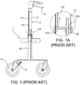
- a conventional hidden braking device 1 includes a brake handle 11, a brake member 12 adapted to control a rotation of a wheel set A, a connecting member 13 connected to the brake handle 11 and the brake member 12, and a main frame 2 connected to the brake handle 11 and the wheel set A.
- the connecting member 13 is disposed inside the main frame 2 which has a lower frame 22 and an upper frame 21 sliding relative to the lower frame 22.
- the connecting member 13 has an upper stem 131 connected to the brake handle 11, a lower stem 132 connected to the brake member 12, and a connecting unit 133 respectively connected to the upper stem 131 and the lower stem 132.
- the connecting unit 133 has a hole 1331 which allows the lower stem 132 to penetrate therethrough.
- the upper stem 131 is fixed to the connecting unit 133 and opposite to the lower stem 132.
- the lower stem 132 slides within the hole 1331, and synchronously the upper stem 131 is moved to a proper place.
- the user grips the brake handle 11 to simultaneously pull the upper stem 131 upwards and allow the connecting unit 133 to become inclined in order that the hole 1331 is engaged with the lower stem 132. Therefore, the lower stem 132 can be moved with the upward movement of the upper stem 131, and further drive the brake member 12 to execute the braking action.
- the repeated braking actions cause the hole 1331 to be worn away easily and cause a size of the hole 1331 to be enlarged gradually.
- the enlarged hole 1331 cannot be engaged with the lower stem 132 effectively, and therefore the lower stem 132 cannot be moved by the connecting unit 133 when the connecting unit 133 is pulled upwards by the upper stem 131, and that causes the lower stem 132 cannot drive the brake member 12 smoothly to result in the ineffective braking action. Hence, the inconvenience of use is increased, and that needs to be improved.
- the user has to grip the brake handle 11 continuously to ensure that the brake member 12 executes the braking action uninterruptedly.
- the brake member 12 is also released to stop the braking action.
- the braking action of the brake member 12 cannot be maintained if the user releases the brake handle 11, and that causes the inconvenience of use and also requires to be improved.
- US 2014/076090 A1 discloses a hidden braking assembly providing a connecting unit disposed inside a main frame.
- the connecting unit includes an upper stem connected to a brake handle, a lower stem connected to a brake unit, and an adjusting set fixed to the lower stem and penetrated by the upper stem.
- US 8 474 838 B1 discloses a hidden braking device installed on an adjustable walking aid and having a connecting unit installed in the walking aid.
- US 2014/076090 A1 discloses a hidden braking assembly according to the preamble of claim 1.
- the object of this invention is to provide a hidden braking device capable of attaining a quick adjustment of a full length of a main frame and increasing the convenience of use and adjustment.
- the hidden braking device of this invention comprises a brake handle, a brake member adapted to control a stop of a wheel set, a connecting member connected to the brake handle and the brake member, and a main frame disposed between the brake handle and the wheel set.
- the connecting member is disposed inside the main frame which has a lower frame and an upper frame sliding relative to the lower frame.
- the connecting member has an upper stem connected to the brake handle, a lower stem connected to the brake member, a locking set disposed on the lower frame, and an adjusting set connected to the upper stem and the lower stem.
- the upper stem is formed with a penetrating sliding trough allowing an insertion of the lower stem and a fixing trough with a plurality of fixing notches formed on a surface of the sliding trough.
- the locking set has a locking body and a locking unit pivotally connected to the locking body.
- the adjusting set has a fixing rod disposed on the lower frame, a main base fixed to the fixing rod, an operating unit movably disposed inside the main base and allowing insertions of the upper stem and the lower stem, a positioning case connected to the lower stem and located in the operating unit, an engaging case engaged with the positioning case, an elastic unit positioned between the positioning case and the engaging case and inserted into the sliding trough to be engaged with the fixing notches, and a first spring unit disposed on the operating unit. While adjusting a full length of the main frame, the locking unit is released to allow the first spring unit to push the operating unit to the engaging case in order to fix the lower stem.
- the upper frame is moved by an outer force to synchronously move the upper stem, and further carry out a movement of the elastic unit caused by the engagement of the elastic unit and the fixing notches .
- the movement of the elastic unit is then restricted by the fixed engaging case to reduce the engaging force, and that facilitates the adjustment. Therefore, the elastic unit is forced to stay motionless in order that only the upper stem is moved.
- the locking unit is fastened to push the operating unit so as to break the engagement of the operating unit and the engaging case and release the lower stem whereby the lower stem and the upper stem can be moved simultaneously.
- a normal braking action can be executed through pressing the brake handle to synchronously pull the upper stem and the lower stem upwards to further stimulate the brake member.
- the full length of the main frame is adjusted quickly and the convenience of use is increased.
- the hidden braking device further comprises a brake control set disposed between the upper stem and the brake handle.
- the brake handle has a front end, a rear end opposite thereof, and a slot formed between the front end and the rear end. The rear end is movable between a neutral position, a normal braking position, and a brake locking position.
- the brake control set has a housing fixed to the upper frame, a shaft fixed to the housing and penetrating the slot, a securing unit disposed inside the housing, a connecting line connected to the upper stem and the housing and driven by the brake handle.
- the securing unit has a first limiting recess and a second limiting recess formed above the first limiting recess. The front end of the brake handle moves from the first limiting recess to the second limiting recess when the rear end of the brake handle assumes the brake locking position.
- the hidden braking device further comprises a pulley disposed on the brake handle.
- the connecting line passes around the pulley and then being fixed to the housing.
- the brake control set has a stem base disposed on the upper stem and connected to the connecting line and a second spring unit disposed between the stem base and the housing.
- the hidden braking device further comprises an engaging recess recessedly formed on a surface of the engaging case and a protruding part projecting from a surface of the operating unit.
- the protruding part is adapted to be inserted into the engaging recess when the operating unit is pushed by the first spring unit.
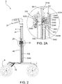
- a first preferred embodiment of a hidden braking device 3 of this invention includes a brake handle 31, a brake member 32 adapted to control a rotation of a wheel set B, a connecting member 33 connected to the brake handle 31 and the brake member 32, and a main frame 4 disposed between the brake handle 31 and the wheel set B.
- the connecting member 33 is disposed inside the main frame 4 which includes an upper frame 41 and a lower frame 42.
- the upper frame 41 is capable of sliding relative to the lower frame 42 so that the upper frame 41 and the lower frame 42 can be expanded or contracted to attain an adjustment of a full length of the main frame 4.
- the connecting member 33 has an upper stem 331 connected to the brake handle 31, a lower stem 332 connected to the brake member 32, a locking set 333 fixed to an end of the lower frame 42 where the upper frame 41 is inserted, and an adjusting set 334 connected to the upper stem 331 and the lower stem 332.
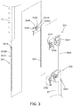
- the upper stem 331 has a sliding trough 3311 penetrating therethrough and adapted for an insertion of the lower stem 332, and a fixing trough 3312 formed with a plurality of fixing notches 33120 formed on a surface of the sliding trough 3311 as shown in Fig. 3 . Referring to Fig. 2A and Fig.
- the locking set 333 has a locking body 3331 fixed on the end of the lower frame 42, and a locking unit 3332 pivotally connected to the locking body 3331 and capable of triggering a movement of an operating unit 3342 of the adjusting set 334.
- the adjusting set 334 has a fixing rod 3340 fixed to the lower frame 42, a main base 3341 fixed to the fixing rod 3340, the operating unit 3342 movably disposed inside the main base 3341 and adapted for insertions of the upper stem 331 and the lower stem 332, a positioning case 3343 connected to the lower stem 332 and located in the operating unit 3342, an engaging case 3344 located relative to the positioning case 3343, an elastic unit 3345 disposed between the positioning case 3343 and the engaging case 3344 and inserted into the sliding trough 3311 to be engaged with the fixing notches 33120, and a first spring unit 3346 disposed on the operating unit 3342 for pushing the operating unit 3342 to the engaging case 3344 in order to position the engaging case 3344 and fix the lower stem 332.
- the elastic unit 3345 has a first end 33451 and a second end 33452 respectively formed on two opposite ends thereof.
- the first end 33451 and the second end 33452 are engaged with different fixing notches 33120 respectively.
- the engaging case 3344 has a first engaging part 33441 capable of restricting the first end 33451, and a second engaging part 33442 capable of restricting the second end 33452.
- the engaging case 3344 has an engaging recess 33440 recessedly formed on a surface of the engaging case 3344.
- the operating unit 3342 has a protruding part 33420 protruding from a surface of the operating unit 3342. The protruding part 33420 is capable of being inserted into the engaging recess 33440 when the operating unit 3342 is pushed by the first spring unit 3346.
- the locking unit 3332 is loosened to allow the first spring unit 3346 to push the operating unit 3342 to the engaging case 3344 until the protruding part 33420 of the operating unit 3342 is inserted into the engaging recess 33440 of the engaging case 3344 to thereby position the engaging case 3344 and fix the lower stem 332.
- the upper frame 41 is moved to simultaneously carry out a movement of the upper stem 331.
- the upper stem 331 when the upper stem 331 is driven by the upper frame 41 to move upwards in order to increase the full length of the main frame 4, the upper stem 331 activates the elastic unit 3345 to move upwards synchronously owing to the engagement of the first end 33451 and the second end 33452 with the fixing notches 33120.
- the first end 33451 is restricted by the first engaging part 33441 to reduce the engaging force of the elastic unit 3345 whereby the elastic unit 3345 is forced to stay at the original place, and that facilitates the upward movement of the upper stem 331.
- the first end 33451 and the second end 33452 are engaged with another fixing notches 33120 again.
- the upper stem 331 when the upper stem 331 is driven by the upper frame 41 to move downwards in order to reduce the full length of the main frame 4, the upper stem 331 also activates the elastic unit 3345 to move downwards.
- the second end 33452 is restricted by the second engaging part 33442 to reduce the engaging force of the elastic unit 3345 whereby the elastic unit 3345 is forced to stay at the original place, and that facilitates the downward movement of the upper stem 331.
- the first end 33451 and the second end 33452 are engaged with another fixing notches 33120 again.
- the locking unit 3332 is fastened to be inserted into the lower frame 42 and the upper frame 41 to further push the operating unit 3342 toward a direction opposite to the engaging case 3344, and therefore force the operating unit 3342 to be separated from the engaging case 3344, namely the protruding part 33420 leaves the engaging recess 33440 to release the engaging case 3344 and the lower stem 332.
- the lower stem 332 is movable with the movement of the upper stem 331.
- the upper stem 331 which is triggered by the brake handle 31 can activate the lower stem 332 synchronously to further stimulate the brake member 32 to execute a braking action.
- FIG. 9 and Fig. 9A show a second preferred embodiment of a hidden braking device 3 of this invention.
- the correlated elements, the concatenation of elements, the operation and objectives of the second preferred embodiment are the same as those of the first preferred embodiment.
- This embodiment is characterised in that a brake control set 34 is disposed between the upper stem 331 and the brake handle 31.
- the brake handle 31 has a front end 311, a rear end 312 opposite to the front end 311, and a slot 313 formed between the front end 311 and the rear end 312.
- the rear end 312 is movable between a neutral position, a normal braking position, and a brake locking position.
- the brake control set 34 has a housing 341 fixed to the upper frame 41, a shaft 342 fixed to the housing 341 and penetrating the slot 313, a securing unit 343 disposed inside the housing 341, a connecting line 344 connected to the upper stem 331 and the housing 341 and driven by the brake handle 31, a pulley 345 disposed on the brake handle 31 and allowing the connecting line 344 to pass around and then being fixed to the housing 341 to thereby reduce the abrasion of the connecting line 344 caused during a braking action, a stem base 346 disposed on the upper stem 331 and connected to the connecting line 344, and a second spring unit 347 disposed between the stem base 346 and the housing 341.
- the securing unit 343 has a first limiting recess 3431 and a second limiting recess 3432 formed on two opposite ends respectively. Further, the second spring unit 347 is capable of pushing the stem base 346 toward a direction opposite to the pulley 345 in order that the connecting line 344 remains taut, thereby smoothing the braking action.
- the rear end 312 before a normal braking action is executed, the rear end 312 is positioned at the neutral position and the front end 311 is located in the first limiting recess 3431.
- the user grips the brake handle 31 to move the rear end 312 to the normal braking position, namely the rear end 312 moves upwards, and simultaneously the front end 311 carries out an upward movement of the pulley 345 to pull the connecting line 344 and the stem base 346 upwards whereby the upper stem 331 is also driven to move upwards so as to activate the lower stem 332 (not shown) and the brake member 32 together to execute the normal braking action.
- the second spring unit 347 pushes the stem base 346 toward the direction opposite to the pulley 345 to thereby tighten the connecting line 344 and move the pulley 345 downwards simultaneously whereby the rear end 312 returns to the neutral position and the normal braking action is stopped.
- the user presses the rear end 312 downwards to position the rear end 312 at the brake locking position and simultaneously move the front end 311 from the first limiting recess 3431 to the second limiting recess 3432.
- the upward movement of the front end 311 moves the pulley 345 upwards and further pulls the connecting line 344, the stem base 346, the upper stem 331 and the lower stem 332 (not shown) upwards whereby the brake member 32 is then activated to attain the uninterrupted braking action.
- the braking action is still maintained because the front end 311 is positioned in the second limiting recess 3432 and that allows the rear end 312 to maintain at the brake locking position.
- the brake member 32 is triggered continuously, thereby attaining the uninterrupted braking action.
- the front end 311 is moved from the second limiting recess 3432 to the first limiting recess 3431, the rear end 312 returns to the neutral position as shown in Fig. 9A , the braking action will be stopped while the user loosens the brake handle 31. Therefore, the uninterrupted braking action can be applied or stopped by engaging the front end 311 with the second limiting recess 3432 or the first limiting recess 3431, thereby attaining an effect of multiple use.
- the hidden braking device of this invention takes advantages of the locking set and the adjusting set to adjust the full length of the main frame quickly.
- the first spring unit pushes the operating unit to allow the operating unit to position the engaging case and further fasten the lower stem.
- the upper frame is adjusted to move the upper stem simultaneously.
- the elastic unit is constrained by the engaging case so as to reduce the engaging force of the elastic unit, and that facilitates the movement of the upper stem, thereby attaining the quick adjustment of the full length of the main frame and increasing the convenience of use.
- the brake control set is adapted to change the braking action into the normal braking action or the uninterrupted braking action by situating the front end in the first limiting recess or the second limiting recess, thereby attaining the effect of multiple use.
Landscapes
- Engineering & Computer Science (AREA)
- Transportation (AREA)
- Mechanical Engineering (AREA)
- Health & Medical Sciences (AREA)
- Epidemiology (AREA)
- Pain & Pain Management (AREA)
- Physical Education & Sports Medicine (AREA)
- Rehabilitation Therapy (AREA)
- Life Sciences & Earth Sciences (AREA)
- Animal Behavior & Ethology (AREA)
- General Health & Medical Sciences (AREA)
- Public Health (AREA)
- Veterinary Medicine (AREA)
- Braking Arrangements (AREA)
Description
- This invention relates to a braking device and relates particularly to a hidden braking device disposed inside a frame.
- Referring to
Fig. 1 and Fig. 1A , a conventional hidden braking device 1 includes abrake handle 11, abrake member 12 adapted to control a rotation of a wheel set A, a connectingmember 13 connected to thebrake handle 11 and thebrake member 12, and amain frame 2 connected to thebrake handle 11 and the wheel set A. The connectingmember 13 is disposed inside themain frame 2 which has alower frame 22 and anupper frame 21 sliding relative to thelower frame 22. The connectingmember 13 has anupper stem 131 connected to thebrake handle 11, alower stem 132 connected to thebrake member 12, and a connectingunit 133 respectively connected to theupper stem 131 and thelower stem 132. The connectingunit 133 has ahole 1331 which allows thelower stem 132 to penetrate therethrough. Theupper stem 131 is fixed to the connectingunit 133 and opposite to thelower stem 132. - While adjusting a full length of the
main frame 2 by expanding or contracting theupper frame 21 and thelower frame 22, thelower stem 132 slides within thehole 1331, and synchronously theupper stem 131 is moved to a proper place. While executing a braking action through thebrake handle 11, the user grips thebrake handle 11 to simultaneously pull theupper stem 131 upwards and allow the connectingunit 133 to become inclined in order that thehole 1331 is engaged with thelower stem 132. Therefore, thelower stem 132 can be moved with the upward movement of theupper stem 131, and further drive thebrake member 12 to execute the braking action. However, the repeated braking actions cause thehole 1331 to be worn away easily and cause a size of thehole 1331 to be enlarged gradually. The enlargedhole 1331 cannot be engaged with thelower stem 132 effectively, and therefore thelower stem 132 cannot be moved by the connectingunit 133 when the connectingunit 133 is pulled upwards by theupper stem 131, and that causes thelower stem 132 cannot drive thebrake member 12 smoothly to result in the ineffective braking action. Hence, the inconvenience of use is increased, and that needs to be improved. - Further, the user has to grip the
brake handle 11 continuously to ensure that thebrake member 12 executes the braking action uninterruptedly. When the user releases thebrake handle 11, thebrake member 12 is also released to stop the braking action. Thus, the braking action of thebrake member 12 cannot be maintained if the user releases thebrake handle 11, and that causes the inconvenience of use and also requires to be improved. -
US 2014/076090 A1 discloses a hidden braking assembly providing a connecting unit disposed inside a main frame. The connecting unit includes an upper stem connected to a brake handle, a lower stem connected to a brake unit, and an adjusting set fixed to the lower stem and penetrated by the upper stem. -
US 8 474 838 B1 discloses a hidden braking device installed on an adjustable walking aid and having a connecting unit installed in the walking aid. - In particular,
US 2014/076090 A1 discloses a hidden braking assembly according to the preamble of claim 1. - The object of this invention is to provide a hidden braking device capable of attaining a quick adjustment of a full length of a main frame and increasing the convenience of use and adjustment.
- The hidden braking device of this invention comprises a brake handle, a brake member adapted to control a stop of a wheel set, a connecting member connected to the brake handle and the brake member, and a main frame disposed between the brake handle and the wheel set. The connecting member is disposed inside the main frame which has a lower frame and an upper frame sliding relative to the lower frame. The connecting member has an upper stem connected to the brake handle, a lower stem connected to the brake member, a locking set disposed on the lower frame, and an adjusting set connected to the upper stem and the lower stem. The upper stem is formed with a penetrating sliding trough allowing an insertion of the lower stem and a fixing trough with a plurality of fixing notches formed on a surface of the sliding trough. The locking set has a locking body and a locking unit pivotally connected to the locking body. The adjusting set has a fixing rod disposed on the lower frame, a main base fixed to the fixing rod, an operating unit movably disposed inside the main base and allowing insertions of the upper stem and the lower stem, a positioning case connected to the lower stem and located in the operating unit, an engaging case engaged with the positioning case, an elastic unit positioned between the positioning case and the engaging case and inserted into the sliding trough to be engaged with the fixing notches, and a first spring unit disposed on the operating unit. While adjusting a full length of the main frame, the locking unit is released to allow the first spring unit to push the operating unit to the engaging case in order to fix the lower stem. And then, the upper frame is moved by an outer force to synchronously move the upper stem, and further carry out a movement of the elastic unit caused by the engagement of the elastic unit and the fixing notches . The movement of the elastic unit is then restricted by the fixed engaging case to reduce the engaging force, and that facilitates the adjustment. Therefore, the elastic unit is forced to stay motionless in order that only the upper stem is moved. After the adjustment is completed, the locking unit is fastened to push the operating unit so as to break the engagement of the operating unit and the engaging case and release the lower stem whereby the lower stem and the upper stem can be moved simultaneously. Thus, a normal braking action can be executed through pressing the brake handle to synchronously pull the upper stem and the lower stem upwards to further stimulate the brake member. Hence, the full length of the main frame is adjusted quickly and the convenience of use is increased.
- Preferably, the hidden braking device further comprises a brake control set disposed between the upper stem and the brake handle. The brake handle has a front end, a rear end opposite thereof, and a slot formed between the front end and the rear end. The rear end is movable between a neutral position, a normal braking position, and a brake locking position. The brake control set has a housing fixed to the upper frame, a shaft fixed to the housing and penetrating the slot, a securing unit disposed inside the housing, a connecting line connected to the upper stem and the housing and driven by the brake handle. The securing unit has a first limiting recess and a second limiting recess formed above the first limiting recess. The front end of the brake handle moves from the first limiting recess to the second limiting recess when the rear end of the brake handle assumes the brake locking position.
- Preferably, the hidden braking device further comprises a pulley disposed on the brake handle. The connecting line passes around the pulley and then being fixed to the housing.
- Preferably, the brake control set has a stem base disposed on the upper stem and connected to the connecting line and a second spring unit disposed between the stem base and the housing.
- Preferably, the hidden braking device further comprises an engaging recess recessedly formed on a surface of the engaging case and a protruding part projecting from a surface of the operating unit. The protruding part is adapted to be inserted into the engaging recess when the operating unit is pushed by the first spring unit.
-
-
Fig. 1 is a schematic view showing a conventional hidden braking device; -
Fig. 1A is an enlarged view of theencircled portion 1A indicated inFig. 1 ; -
Fig. 2 is a schematic view showing a first preferred embodiment of this invention; -
Fig. 2A is an enlarged view of theencircled portion 2A indicated inFig. 2 ; -
Fig. 3 is an exploded view showing the connecting member; -
Fig. 4 is a cross-sectional showing that the elastic unit is engaged with the fixing notches to thereby connect the upper stem and the lower stem together; -
Fig. 5 is a cross-sectional showing that the locking unit is released to allow the first spring unit to push the operating unit to thereby position the engaging case and fix the lower stem; -
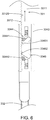
Fig. 6 is a cross-sectional showing that the first end of the elastic unit is constrained by the first engaging part of the engaging case when the upper stem is moved upwards; -
Fig. 7 is a cross-sectional showing that the second end of the elastic unit is constrained by the second engaging part of the engaging case when the upper stem is moved downwards; -
Fig. 8 is a cross-sectional showing that the locking unit is fastened to push the operating unit and release the engaging case whereby the lower stem is movable with a movement of the upper stem; -
Fig. 9 is a schematic view showing a second preferred embodiment of this invention; -
Fig. 9A is an enlarged view of the encircledportion 9A indicated inFig. 9 and showing a neutral position of the brake handle; -
Fig. 10 is a cross-sectional view showing that the brake handle is engaged with the first limiting recess and griped to execute a normal braking action; and -
Fig. 11 is a cross-sectional view showing that the brake handle is engaged with the second limiting recess to execute an uninterrupted braking action. - Referring to
Fig. 2 and Fig. 2A , a first preferred embodiment of a hiddenbraking device 3 of this invention includes abrake handle 31, abrake member 32 adapted to control a rotation of a wheel set B, a connectingmember 33 connected to thebrake handle 31 and thebrake member 32, and amain frame 4 disposed between thebrake handle 31 and the wheel set B. The connectingmember 33 is disposed inside themain frame 4 which includes anupper frame 41 and alower frame 42. Theupper frame 41 is capable of sliding relative to thelower frame 42 so that theupper frame 41 and thelower frame 42 can be expanded or contracted to attain an adjustment of a full length of themain frame 4. The connectingmember 33 has anupper stem 331 connected to thebrake handle 31, alower stem 332 connected to thebrake member 32, a locking set 333 fixed to an end of thelower frame 42 where theupper frame 41 is inserted, and an adjusting set 334 connected to theupper stem 331 and thelower stem 332. Theupper stem 331 has a slidingtrough 3311 penetrating therethrough and adapted for an insertion of thelower stem 332, and afixing trough 3312 formed with a plurality of fixingnotches 33120 formed on a surface of the slidingtrough 3311 as shown inFig. 3 . Referring toFig. 2A andFig. 3 , the locking set 333 has alocking body 3331 fixed on the end of thelower frame 42, and alocking unit 3332 pivotally connected to thelocking body 3331 and capable of triggering a movement of anoperating unit 3342 of the adjusting set 334. The adjusting set 334 has a fixingrod 3340 fixed to thelower frame 42, amain base 3341 fixed to the fixingrod 3340, theoperating unit 3342 movably disposed inside themain base 3341 and adapted for insertions of theupper stem 331 and thelower stem 332, apositioning case 3343 connected to thelower stem 332 and located in theoperating unit 3342, an engagingcase 3344 located relative to thepositioning case 3343, anelastic unit 3345 disposed between thepositioning case 3343 and theengaging case 3344 and inserted into the slidingtrough 3311 to be engaged with the fixingnotches 33120, and afirst spring unit 3346 disposed on theoperating unit 3342 for pushing theoperating unit 3342 to theengaging case 3344 in order to position the engagingcase 3344 and fix thelower stem 332. - Referring to
Fig. 4 , theelastic unit 3345 has afirst end 33451 and asecond end 33452 respectively formed on two opposite ends thereof. Thefirst end 33451 and thesecond end 33452 are engaged withdifferent fixing notches 33120 respectively. The engagingcase 3344 has a firstengaging part 33441 capable of restricting thefirst end 33451, and a secondengaging part 33442 capable of restricting thesecond end 33452. In this embodiment, as shown inFig. 2A , the engagingcase 3344 has anengaging recess 33440 recessedly formed on a surface of theengaging case 3344. Theoperating unit 3342 has aprotruding part 33420 protruding from a surface of theoperating unit 3342. The protrudingpart 33420 is capable of being inserted into the engagingrecess 33440 when theoperating unit 3342 is pushed by thefirst spring unit 3346. - Referring to
Fig. 5 , during executing the adjustment of the full length of themain frame 4, thelocking unit 3332 is loosened to allow thefirst spring unit 3346 to push theoperating unit 3342 to theengaging case 3344 until theprotruding part 33420 of theoperating unit 3342 is inserted into the engagingrecess 33440 of theengaging case 3344 to thereby position the engagingcase 3344 and fix thelower stem 332. After thelower stem 332 is fastened by the engagement of theengaging case 3344 and theoperating unit 3342, theupper frame 41 is moved to simultaneously carry out a movement of theupper stem 331. Referring toFig. 5 andFig. 6 , when theupper stem 331 is driven by theupper frame 41 to move upwards in order to increase the full length of themain frame 4, theupper stem 331 activates theelastic unit 3345 to move upwards synchronously owing to the engagement of thefirst end 33451 and thesecond end 33452 with the fixingnotches 33120. At the same time, thefirst end 33451 is restricted by the firstengaging part 33441 to reduce the engaging force of theelastic unit 3345 whereby theelastic unit 3345 is forced to stay at the original place, and that facilitates the upward movement of theupper stem 331. When the adjustment is finished and theupper stem 331 stops moving, thefirst end 33451 and thesecond end 33452 are engaged with another fixingnotches 33120 again. - On the contrary, referring to
Fig.5 andFig. 7 , when theupper stem 331 is driven by theupper frame 41 to move downwards in order to reduce the full length of themain frame 4, theupper stem 331 also activates theelastic unit 3345 to move downwards. At the same time, thesecond end 33452 is restricted by the secondengaging part 33442 to reduce the engaging force of theelastic unit 3345 whereby theelastic unit 3345 is forced to stay at the original place, and that facilitates the downward movement of theupper stem 331. When the adjustment is finished and theupper stem 331 stops moving, thefirst end 33451 and thesecond end 33452 are engaged with another fixingnotches 33120 again. Thus, the quick adjustment of the full length of themain frame 4 is attained and the convenience of use is increased effectively. - Referring to
Fig. 8 , after the adjustment of the full length of themain frame 4 is completed, thelocking unit 3332 is fastened to be inserted into thelower frame 42 and theupper frame 41 to further push theoperating unit 3342 toward a direction opposite to theengaging case 3344, and therefore force theoperating unit 3342 to be separated from the engagingcase 3344, namely theprotruding part 33420 leaves theengaging recess 33440 to release theengaging case 3344 and thelower stem 332. Thus, thelower stem 332 is movable with the movement of theupper stem 331. Hence, theupper stem 331 which is triggered by the brake handle 31 can activate thelower stem 332 synchronously to further stimulate thebrake member 32 to execute a braking action. - Referring to
Fig. 9 and Fig. 9A show a second preferred embodiment of a hiddenbraking device 3 of this invention. The correlated elements, the concatenation of elements, the operation and objectives of the second preferred embodiment are the same as those of the first preferred embodiment. This embodiment is characterised in that a brake control set 34 is disposed between theupper stem 331 and thebrake handle 31. The brake handle 31 has afront end 311, arear end 312 opposite to thefront end 311, and aslot 313 formed between thefront end 311 and therear end 312. Therear end 312 is movable between a neutral position, a normal braking position, and a brake locking position. The brake control set 34 has ahousing 341 fixed to theupper frame 41, ashaft 342 fixed to thehousing 341 and penetrating theslot 313, a securingunit 343 disposed inside thehousing 341, a connectingline 344 connected to theupper stem 331 and thehousing 341 and driven by thebrake handle 31, apulley 345 disposed on thebrake handle 31 and allowing the connectingline 344 to pass around and then being fixed to thehousing 341 to thereby reduce the abrasion of the connectingline 344 caused during a braking action, astem base 346 disposed on theupper stem 331 and connected to the connectingline 344, and asecond spring unit 347 disposed between thestem base 346 and thehousing 341. The securingunit 343 has a first limitingrecess 3431 and a second limitingrecess 3432 formed on two opposite ends respectively. Further, thesecond spring unit 347 is capable of pushing thestem base 346 toward a direction opposite to thepulley 345 in order that the connectingline 344 remains taut, thereby smoothing the braking action. - Referring to
Fig. 9, Fig. 9A , before a normal braking action is executed, therear end 312 is positioned at the neutral position and thefront end 311 is located in the first limitingrecess 3431. Referring toFig. 10 , in order to execute the normal braking action, the user grips the brake handle 31 to move therear end 312 to the normal braking position, namely therear end 312 moves upwards, and simultaneously thefront end 311 carries out an upward movement of thepulley 345 to pull the connectingline 344 and thestem base 346 upwards whereby theupper stem 331 is also driven to move upwards so as to activate the lower stem 332 (not shown) and thebrake member 32 together to execute the normal braking action. When releasing thebrake handle 31, thesecond spring unit 347 pushes thestem base 346 toward the direction opposite to thepulley 345 to thereby tighten the connectingline 344 and move thepulley 345 downwards simultaneously whereby therear end 312 returns to the neutral position and the normal braking action is stopped. - Referring to
Fig. 9 andFig. 11 , in order to fasten the brake handle 31 so as to execute an uninterrupted braking action, the user presses therear end 312 downwards to position therear end 312 at the brake locking position and simultaneously move thefront end 311 from the first limitingrecess 3431 to the second limitingrecess 3432. The upward movement of thefront end 311 moves thepulley 345 upwards and further pulls the connectingline 344, thestem base 346, theupper stem 331 and the lower stem 332 (not shown) upwards whereby thebrake member 32 is then activated to attain the uninterrupted braking action. When the user loosens thebrake handle 31, the braking action is still maintained because thefront end 311 is positioned in the second limitingrecess 3432 and that allows therear end 312 to maintain at the brake locking position. Thus, thebrake member 32 is triggered continuously, thereby attaining the uninterrupted braking action. On the contrary, when thefront end 311 is moved from the second limitingrecess 3432 to the first limitingrecess 3431, therear end 312 returns to the neutral position as shown inFig. 9A , the braking action will be stopped while the user loosens thebrake handle 31. Therefore, the uninterrupted braking action can be applied or stopped by engaging thefront end 311 with the second limitingrecess 3432 or the first limitingrecess 3431, thereby attaining an effect of multiple use. - To sum up, the hidden braking device of this invention takes advantages of the locking set and the adjusting set to adjust the full length of the main frame quickly. When loosening the locking unit, the first spring unit pushes the operating unit to allow the operating unit to position the engaging case and further fasten the lower stem. And then, the upper frame is adjusted to move the upper stem simultaneously. When the upper stem is moved, the elastic unit is constrained by the engaging case so as to reduce the engaging force of the elastic unit, and that facilitates the movement of the upper stem, thereby attaining the quick adjustment of the full length of the main frame and increasing the convenience of use. Moreover, the brake control set is adapted to change the braking action into the normal braking action or the uninterrupted braking action by situating the front end in the first limiting recess or the second limiting recess, thereby attaining the effect of multiple use.
- While the embodiments of this invention are shown and described, it is understood that further variations and modifications may be made without departing from the scope of this invention. The invention is only limited within the scope of the appended claims.
Claims (5)
- A hidden braking device (3) comprising a brake handle (31), a brake member (32) adapted to control a rotation of a wheel set (B), a connecting member (33) connected to said brake handle (31) and said brake member (32), and a main frame (4) disposed between said brake handle (31) and said wheel set (B), wherein said connecting member (33) is disposed inside said main frame (4), said main frame (4) including a lower frame (42) and an upper frame (41) sliding relative to said lower frame (42) to attain an adjustment of a full length of said main frame (4),said connecting member (33) including an upper stem (331) connected to said brake handle (31) and a lower stem (332) connected to said brake member (32),characterised in that said connecting member (33) includes a locking set (333) disposed at an end of said lower frame (42) where said upper frame (41) is inserted and an adjusting set (334) connected to said upper stem (331) and said lower stem (332), said upper stem (331) including a sliding trough (3311) adapted for an insertion of said lower stem (332) and a fixing trough (3312) with a plurality of fixing notches (33120) formed on a surface of said sliding trough (3311), said locking set (333) including a locking body (3331) disposed on said end of said lower frame (42) and a locking unit (3332) pivotally connected to said locking body (3331) and capable of triggering a movement of an operating unit (3342) of said adjusting set (334), said adjusting set (334) including a fixing rod (3340) disposed on said lower frame (42), a main base (3341) fixed to said fixing rod (3340), said operating unit (3342) movably disposed inside said main base (3341) and adapted for insertions of said upper stem (331) and said lower stem (332), a positioning case (3343) connected to said lower stem (332) and located in said operating unit (3342), an engaging case (3344) disposed relative to said positioning case (3343), an elastic unit (3345) disposed between said positioning case (3343) and said engaging case (3344) and having a first end (33451) and a second end (33452) engaged with different ones of said plurality of fixing notches (33120), and a first spring unit (3346) disposed on said operating unit (3342) and capable of pushing said operating unit (3342) to said engaging case (3344) to thereby position said engaging case (3344), said engaging case (3344) including a first engaging part (33441) capable of restricting said first end (33451) of said elastic unit (3345) and a second engaging part (33442) capable of restricting said second end (33452) of said elastic unit (3345) when said main frame (4) operates the adjustment of said full length.
- The hidden braking device (3) as claimed in claim 1, further comprising a brake control set (34) disposed between said upper stem (331) and said brake handle (31), said brake handle (31) having a front end (311), a rear end (312) opposite to said front end (311), and a slot (313) formed between said front end (311) and said rear end (312), said rear end (312) being movable between a neutral position, a normal braking position, and a brake locking position, said brake control set (34) including a housing (341) fixed to said upper frame (41), a shaft (342) fixed to said housing (341) and penetrating said slot (313) of said brake handle (31), a securing unit (343) disposed inside said housing (341), and a connecting line (344) connected to said upper stem (331) and said housing (341) and driven by said brake handle (31), said securing unit (343) including a first limiting recess (3431) and a second limiting recess (3432) formed above said first limiting recess (3431), said front end (311) of said brake handle (31) moving from said first limiting recess (3431) to said second limiting recess (3432) when said rear end (312) of said brake handle (31) assumes said brake locking position.
- The hidden braking device (3) as claimed in claim 2, further comprising a pulley (345) disposed on said brake handle (31), said connecting line (344) passing around said pulley (345) and then being fixed to said housing (341).
- The hidden braking device (3) as claimed in claim 2, wherein said brake control set (34) includes a stem base (346) disposed on said upper stem (331) and connected to said connecting line (344) and a second spring unit (347) disposed between said stem base (346) and said housing (341).
- The hidden braking device (3) as claimed in claim 1 or 2, further comprising an engaging recess (33440) recessedly formed on a surface of said engaging case (3344) and a protruding part (33420) projecting from a surface of said operating unit (3342), said protruding part (33420) being adapted to be inserted into said engaging recess (33440) when said operating unit (3342) is pushed by said first spring unit (3346).
Priority Applications (1)
| Application Number | Priority Date | Filing Date | Title |
|---|---|---|---|
| EP19202939.5A EP3705365B1 (en) | 2019-10-14 | 2019-10-14 | Hidden braking device |
Applications Claiming Priority (1)
| Application Number | Priority Date | Filing Date | Title |
|---|---|---|---|
| EP19202939.5A EP3705365B1 (en) | 2019-10-14 | 2019-10-14 | Hidden braking device |
Publications (2)
| Publication Number | Publication Date |
|---|---|
| EP3705365A1 EP3705365A1 (en) | 2020-09-09 |
| EP3705365B1 true EP3705365B1 (en) | 2021-12-08 |
Family
ID=68290165
Family Applications (1)
| Application Number | Title | Priority Date | Filing Date |
|---|---|---|---|
| EP19202939.5A Not-in-force EP3705365B1 (en) | 2019-10-14 | 2019-10-14 | Hidden braking device |
Country Status (1)
| Country | Link |
|---|---|
| EP (1) | EP3705365B1 (en) |
Family Cites Families (2)
| Publication number | Priority date | Publication date | Assignee | Title |
|---|---|---|---|---|
| US8474838B1 (en) * | 2012-02-16 | 2013-07-02 | Ching-Tsang Wu | Hidden braking device |
| TWM449760U (en) * | 2012-09-19 | 2013-04-01 | Shen-Ji Cai | Built-in braking apparatus |
-
2019
- 2019-10-14 EP EP19202939.5A patent/EP3705365B1/en not_active Not-in-force
Non-Patent Citations (1)
| Title |
|---|
| None * |
Also Published As
| Publication number | Publication date |
|---|---|
| EP3705365A1 (en) | 2020-09-09 |
Similar Documents
| Publication | Publication Date | Title |
|---|---|---|
| US6851595B1 (en) | Nail beating depth adjuster | |
| US6463825B2 (en) | Brake turntable for actuating a brake system for a walker | |
| US11318919B2 (en) | Hidden braking device | |
| KR20080057301A (en) | Metal tie tool with rotary gripper and ball setting device | |
| JP2537504B2 (en) | Brake pressure contact force control device | |
| US9062749B2 (en) | Hidden braking assembly | |
| US20050061587A1 (en) | Brake device having adjustable spring member | |
| KR101902498B1 (en) | Screw-twist locking apparatus for trekking pole | |
| JPH0130655Y2 (en) | ||
| JP3247703U (en) | Adjustment mechanism for telescopic rod | |
| AU2014393342A1 (en) | Telescopic rod for hand tool | |
| EP1435208A2 (en) | Automatic openable and closable umbrella | |
| EP3705365A1 (en) | Hidden braking device | |
| US5642555A (en) | Press-type fastener | |
| US20200385970A1 (en) | Drain plug linkage arrangement | |
| US7540093B1 (en) | Gardening shears | |
| US6938307B2 (en) | Shoelace fastener | |
| US11752605B2 (en) | Connecting tool | |
| JPH0394702A (en) | Adjustable binding device for sports shoe, and sports shoe using its device | |
| KR101858208B1 (en) | Rivet gun having punching unit | |
| US5853069A (en) | Mechanism for microadjusting bicycle brake tension | |
| CN112550545B (en) | Built-in brake device | |
| EP3278845B1 (en) | Fitness bike with a braking device | |
| GB2370802A (en) | Expandable tubular body, especially a handle | |
| CN100493832C (en) | Clamping device for multi-section extension rod of cutting machine |
Legal Events
| Date | Code | Title | Description |
|---|---|---|---|
| PUAI | Public reference made under article 153(3) epc to a published international application that has entered the european phase |
Free format text: ORIGINAL CODE: 0009012 |
|
| STAA | Information on the status of an ep patent application or granted ep patent |
Free format text: STATUS: THE APPLICATION HAS BEEN PUBLISHED |
|
| STAA | Information on the status of an ep patent application or granted ep patent |
Free format text: STATUS: REQUEST FOR EXAMINATION WAS MADE |
|
| AK | Designated contracting states |
Kind code of ref document: A1 Designated state(s): AL AT BE BG CH CY CZ DE DK EE ES FI FR GB GR HR HU IE IS IT LI LT LU LV MC MK MT NL NO PL PT RO RS SE SI SK SM TR |
|
| AX | Request for extension of the european patent |
Extension state: BA ME |
|
| 17P | Request for examination filed |
Effective date: 20200807 |
|
| RBV | Designated contracting states (corrected) |
Designated state(s): AL AT BE BG CH CY CZ DE DK EE ES FI FR GB GR HR HU IE IS IT LI LT LU LV MC MK MT NL NO PL PT RO RS SE SI SK SM TR |
|
| GRAP | Despatch of communication of intention to grant a patent |
Free format text: ORIGINAL CODE: EPIDOSNIGR1 |
|
| STAA | Information on the status of an ep patent application or granted ep patent |
Free format text: STATUS: GRANT OF PATENT IS INTENDED |
|
| INTG | Intention to grant announced |
Effective date: 20210528 |
|
| GRAS | Grant fee paid |
Free format text: ORIGINAL CODE: EPIDOSNIGR3 |
|
| GRAA | (expected) grant |
Free format text: ORIGINAL CODE: 0009210 |
|
| STAA | Information on the status of an ep patent application or granted ep patent |
Free format text: STATUS: THE PATENT HAS BEEN GRANTED |
|
| AK | Designated contracting states |
Kind code of ref document: B1 Designated state(s): AL AT BE BG CH CY CZ DE DK EE ES FI FR GB GR HR HU IE IS IT LI LT LU LV MC MK MT NL NO PL PT RO RS SE SI SK SM TR |
|
| REG | Reference to a national code |
Ref country code: GB Ref legal event code: FG4D |
|
| REG | Reference to a national code |
Ref country code: AT Ref legal event code: REF Ref document number: 1453550 Country of ref document: AT Kind code of ref document: T Effective date: 20211215 Ref country code: CH Ref legal event code: EP |
|
| REG | Reference to a national code |
Ref country code: DE Ref legal event code: R096 Ref document number: 602019009878 Country of ref document: DE |
|
| REG | Reference to a national code |
Ref country code: IE Ref legal event code: FG4D |
|
| REG | Reference to a national code |
Ref country code: LT Ref legal event code: MG9D |
|
| REG | Reference to a national code |
Ref country code: NL Ref legal event code: MP Effective date: 20211208 |
|
| PG25 | Lapsed in a contracting state [announced via postgrant information from national office to epo] |
Ref country code: RS Free format text: LAPSE BECAUSE OF FAILURE TO SUBMIT A TRANSLATION OF THE DESCRIPTION OR TO PAY THE FEE WITHIN THE PRESCRIBED TIME-LIMIT Effective date: 20211208 Ref country code: LT Free format text: LAPSE BECAUSE OF FAILURE TO SUBMIT A TRANSLATION OF THE DESCRIPTION OR TO PAY THE FEE WITHIN THE PRESCRIBED TIME-LIMIT Effective date: 20211208 Ref country code: FI Free format text: LAPSE BECAUSE OF FAILURE TO SUBMIT A TRANSLATION OF THE DESCRIPTION OR TO PAY THE FEE WITHIN THE PRESCRIBED TIME-LIMIT Effective date: 20211208 Ref country code: BG Free format text: LAPSE BECAUSE OF FAILURE TO SUBMIT A TRANSLATION OF THE DESCRIPTION OR TO PAY THE FEE WITHIN THE PRESCRIBED TIME-LIMIT Effective date: 20220308 |
|
| REG | Reference to a national code |
Ref country code: AT Ref legal event code: MK05 Ref document number: 1453550 Country of ref document: AT Kind code of ref document: T Effective date: 20211208 |
|
| PG25 | Lapsed in a contracting state [announced via postgrant information from national office to epo] |
Ref country code: SE Free format text: LAPSE BECAUSE OF FAILURE TO SUBMIT A TRANSLATION OF THE DESCRIPTION OR TO PAY THE FEE WITHIN THE PRESCRIBED TIME-LIMIT Effective date: 20211208 Ref country code: NO Free format text: LAPSE BECAUSE OF FAILURE TO SUBMIT A TRANSLATION OF THE DESCRIPTION OR TO PAY THE FEE WITHIN THE PRESCRIBED TIME-LIMIT Effective date: 20220308 Ref country code: LV Free format text: LAPSE BECAUSE OF FAILURE TO SUBMIT A TRANSLATION OF THE DESCRIPTION OR TO PAY THE FEE WITHIN THE PRESCRIBED TIME-LIMIT Effective date: 20211208 Ref country code: HR Free format text: LAPSE BECAUSE OF FAILURE TO SUBMIT A TRANSLATION OF THE DESCRIPTION OR TO PAY THE FEE WITHIN THE PRESCRIBED TIME-LIMIT Effective date: 20211208 Ref country code: GR Free format text: LAPSE BECAUSE OF FAILURE TO SUBMIT A TRANSLATION OF THE DESCRIPTION OR TO PAY THE FEE WITHIN THE PRESCRIBED TIME-LIMIT Effective date: 20220309 |
|
| PG25 | Lapsed in a contracting state [announced via postgrant information from national office to epo] |
Ref country code: NL Free format text: LAPSE BECAUSE OF FAILURE TO SUBMIT A TRANSLATION OF THE DESCRIPTION OR TO PAY THE FEE WITHIN THE PRESCRIBED TIME-LIMIT Effective date: 20211208 |
|
| PG25 | Lapsed in a contracting state [announced via postgrant information from national office to epo] |
Ref country code: SM Free format text: LAPSE BECAUSE OF FAILURE TO SUBMIT A TRANSLATION OF THE DESCRIPTION OR TO PAY THE FEE WITHIN THE PRESCRIBED TIME-LIMIT Effective date: 20211208 Ref country code: SK Free format text: LAPSE BECAUSE OF FAILURE TO SUBMIT A TRANSLATION OF THE DESCRIPTION OR TO PAY THE FEE WITHIN THE PRESCRIBED TIME-LIMIT Effective date: 20211208 Ref country code: RO Free format text: LAPSE BECAUSE OF FAILURE TO SUBMIT A TRANSLATION OF THE DESCRIPTION OR TO PAY THE FEE WITHIN THE PRESCRIBED TIME-LIMIT Effective date: 20211208 Ref country code: PT Free format text: LAPSE BECAUSE OF FAILURE TO SUBMIT A TRANSLATION OF THE DESCRIPTION OR TO PAY THE FEE WITHIN THE PRESCRIBED TIME-LIMIT Effective date: 20220408 Ref country code: ES Free format text: LAPSE BECAUSE OF FAILURE TO SUBMIT A TRANSLATION OF THE DESCRIPTION OR TO PAY THE FEE WITHIN THE PRESCRIBED TIME-LIMIT Effective date: 20211208 Ref country code: EE Free format text: LAPSE BECAUSE OF FAILURE TO SUBMIT A TRANSLATION OF THE DESCRIPTION OR TO PAY THE FEE WITHIN THE PRESCRIBED TIME-LIMIT Effective date: 20211208 Ref country code: CZ Free format text: LAPSE BECAUSE OF FAILURE TO SUBMIT A TRANSLATION OF THE DESCRIPTION OR TO PAY THE FEE WITHIN THE PRESCRIBED TIME-LIMIT Effective date: 20211208 |
|
| PG25 | Lapsed in a contracting state [announced via postgrant information from national office to epo] |
Ref country code: PL Free format text: LAPSE BECAUSE OF FAILURE TO SUBMIT A TRANSLATION OF THE DESCRIPTION OR TO PAY THE FEE WITHIN THE PRESCRIBED TIME-LIMIT Effective date: 20211208 Ref country code: AT Free format text: LAPSE BECAUSE OF FAILURE TO SUBMIT A TRANSLATION OF THE DESCRIPTION OR TO PAY THE FEE WITHIN THE PRESCRIBED TIME-LIMIT Effective date: 20211208 |
|
| REG | Reference to a national code |
Ref country code: DE Ref legal event code: R097 Ref document number: 602019009878 Country of ref document: DE |
|
| PG25 | Lapsed in a contracting state [announced via postgrant information from national office to epo] |
Ref country code: IS Free format text: LAPSE BECAUSE OF FAILURE TO SUBMIT A TRANSLATION OF THE DESCRIPTION OR TO PAY THE FEE WITHIN THE PRESCRIBED TIME-LIMIT Effective date: 20220408 |
|
| PLBE | No opposition filed within time limit |
Free format text: ORIGINAL CODE: 0009261 |
|
| STAA | Information on the status of an ep patent application or granted ep patent |
Free format text: STATUS: NO OPPOSITION FILED WITHIN TIME LIMIT |
|
| PG25 | Lapsed in a contracting state [announced via postgrant information from national office to epo] |
Ref country code: DK Free format text: LAPSE BECAUSE OF FAILURE TO SUBMIT A TRANSLATION OF THE DESCRIPTION OR TO PAY THE FEE WITHIN THE PRESCRIBED TIME-LIMIT Effective date: 20211208 Ref country code: AL Free format text: LAPSE BECAUSE OF FAILURE TO SUBMIT A TRANSLATION OF THE DESCRIPTION OR TO PAY THE FEE WITHIN THE PRESCRIBED TIME-LIMIT Effective date: 20211208 |
|
| 26N | No opposition filed |
Effective date: 20220909 |
|
| PG25 | Lapsed in a contracting state [announced via postgrant information from national office to epo] |
Ref country code: SI Free format text: LAPSE BECAUSE OF FAILURE TO SUBMIT A TRANSLATION OF THE DESCRIPTION OR TO PAY THE FEE WITHIN THE PRESCRIBED TIME-LIMIT Effective date: 20211208 |
|
| PGFP | Annual fee paid to national office [announced via postgrant information from national office to epo] |
Ref country code: FR Payment date: 20221027 Year of fee payment: 4 |
|
| PGFP | Annual fee paid to national office [announced via postgrant information from national office to epo] |
Ref country code: DE Payment date: 20221027 Year of fee payment: 4 |
|
| PG25 | Lapsed in a contracting state [announced via postgrant information from national office to epo] |
Ref country code: MC Free format text: LAPSE BECAUSE OF FAILURE TO SUBMIT A TRANSLATION OF THE DESCRIPTION OR TO PAY THE FEE WITHIN THE PRESCRIBED TIME-LIMIT Effective date: 20211208 Ref country code: IT Free format text: LAPSE BECAUSE OF FAILURE TO SUBMIT A TRANSLATION OF THE DESCRIPTION OR TO PAY THE FEE WITHIN THE PRESCRIBED TIME-LIMIT Effective date: 20211208 |
|
| REG | Reference to a national code |
Ref country code: CH Ref legal event code: PL |
|
| REG | Reference to a national code |
Ref country code: BE Ref legal event code: MM Effective date: 20221031 |
|
| PG25 | Lapsed in a contracting state [announced via postgrant information from national office to epo] |
Ref country code: LU Free format text: LAPSE BECAUSE OF NON-PAYMENT OF DUE FEES Effective date: 20221014 |
|
| PG25 | Lapsed in a contracting state [announced via postgrant information from national office to epo] |
Ref country code: LI Free format text: LAPSE BECAUSE OF NON-PAYMENT OF DUE FEES Effective date: 20221031 Ref country code: CH Free format text: LAPSE BECAUSE OF NON-PAYMENT OF DUE FEES Effective date: 20221031 |
|
| PG25 | Lapsed in a contracting state [announced via postgrant information from national office to epo] |
Ref country code: BE Free format text: LAPSE BECAUSE OF NON-PAYMENT OF DUE FEES Effective date: 20221031 |
|
| PG25 | Lapsed in a contracting state [announced via postgrant information from national office to epo] |
Ref country code: IE Free format text: LAPSE BECAUSE OF NON-PAYMENT OF DUE FEES Effective date: 20221014 |
|
| PG25 | Lapsed in a contracting state [announced via postgrant information from national office to epo] |
Ref country code: CY Free format text: LAPSE BECAUSE OF FAILURE TO SUBMIT A TRANSLATION OF THE DESCRIPTION OR TO PAY THE FEE WITHIN THE PRESCRIBED TIME-LIMIT Effective date: 20211208 |
|
| REG | Reference to a national code |
Ref country code: DE Ref legal event code: R119 Ref document number: 602019009878 Country of ref document: DE |
|
| PG25 | Lapsed in a contracting state [announced via postgrant information from national office to epo] |
Ref country code: MK Free format text: LAPSE BECAUSE OF FAILURE TO SUBMIT A TRANSLATION OF THE DESCRIPTION OR TO PAY THE FEE WITHIN THE PRESCRIBED TIME-LIMIT Effective date: 20211208 Ref country code: HU Free format text: LAPSE BECAUSE OF FAILURE TO SUBMIT A TRANSLATION OF THE DESCRIPTION OR TO PAY THE FEE WITHIN THE PRESCRIBED TIME-LIMIT; INVALID AB INITIO Effective date: 20191014 |
|
| GBPC | Gb: european patent ceased through non-payment of renewal fee |
Effective date: 20231014 |
|
| PG25 | Lapsed in a contracting state [announced via postgrant information from national office to epo] |
Ref country code: GB Free format text: LAPSE BECAUSE OF NON-PAYMENT OF DUE FEES Effective date: 20231014 |
|
| PG25 | Lapsed in a contracting state [announced via postgrant information from national office to epo] |
Ref country code: GB Free format text: LAPSE BECAUSE OF NON-PAYMENT OF DUE FEES Effective date: 20231014 Ref country code: FR Free format text: LAPSE BECAUSE OF NON-PAYMENT OF DUE FEES Effective date: 20231031 Ref country code: DE Free format text: LAPSE BECAUSE OF NON-PAYMENT OF DUE FEES Effective date: 20240501 |
|
| PG25 | Lapsed in a contracting state [announced via postgrant information from national office to epo] |
Ref country code: MT Free format text: LAPSE BECAUSE OF FAILURE TO SUBMIT A TRANSLATION OF THE DESCRIPTION OR TO PAY THE FEE WITHIN THE PRESCRIBED TIME-LIMIT Effective date: 20211208 |
|
| PG25 | Lapsed in a contracting state [announced via postgrant information from national office to epo] |
Ref country code: TR Free format text: LAPSE BECAUSE OF FAILURE TO SUBMIT A TRANSLATION OF THE DESCRIPTION OR TO PAY THE FEE WITHIN THE PRESCRIBED TIME-LIMIT Effective date: 20211208 |