EP3705324A1 - A system and a method for a vehicle air-conditioner - Google Patents
A system and a method for a vehicle air-conditioner Download PDFInfo
- Publication number
- EP3705324A1 EP3705324A1 EP19160641.7A EP19160641A EP3705324A1 EP 3705324 A1 EP3705324 A1 EP 3705324A1 EP 19160641 A EP19160641 A EP 19160641A EP 3705324 A1 EP3705324 A1 EP 3705324A1
- Authority
- EP
- European Patent Office
- Prior art keywords
- condenser
- evaporator
- section
- condensation water
- refrigerant
- Prior art date
- Legal status (The legal status is an assumption and is not a legal conclusion. Google has not performed a legal analysis and makes no representation as to the accuracy of the status listed.)
- Withdrawn
Links
Images



Classifications
-
- B—PERFORMING OPERATIONS; TRANSPORTING
- B60—VEHICLES IN GENERAL
- B60H—ARRANGEMENTS OF HEATING, COOLING, VENTILATING OR OTHER AIR-TREATING DEVICES SPECIALLY ADAPTED FOR PASSENGER OR GOODS SPACES OF VEHICLES
- B60H1/00—Heating, cooling or ventilating devices
- B60H1/32—Cooling devices
- B60H1/3233—Cooling devices characterised by condensed liquid drainage means
- B60H1/32331—Cooling devices characterised by condensed liquid drainage means comprising means for the use of condensed liquid, e.g. for humidification or for improving condenser performance
-
- B—PERFORMING OPERATIONS; TRANSPORTING
- B61—RAILWAYS
- B61D—BODY DETAILS OR KINDS OF RAILWAY VEHICLES
- B61D27/00—Heating, cooling, ventilating, or air-conditioning
- B61D27/0072—Means for cooling only
-
- F—MECHANICAL ENGINEERING; LIGHTING; HEATING; WEAPONS; BLASTING
- F24—HEATING; RANGES; VENTILATING
- F24F—AIR-CONDITIONING; AIR-HUMIDIFICATION; VENTILATION; USE OF AIR CURRENTS FOR SCREENING
- F24F13/00—Details common to, or for air-conditioning, air-humidification, ventilation or use of air currents for screening
- F24F13/22—Means for preventing condensation or evacuating condensate
- F24F13/222—Means for preventing condensation or evacuating condensate for evacuating condensate
-
- B—PERFORMING OPERATIONS; TRANSPORTING
- B60—VEHICLES IN GENERAL
- B60H—ARRANGEMENTS OF HEATING, COOLING, VENTILATING OR OTHER AIR-TREATING DEVICES SPECIALLY ADAPTED FOR PASSENGER OR GOODS SPACES OF VEHICLES
- B60H1/00—Heating, cooling or ventilating devices
- B60H1/00357—Air-conditioning arrangements specially adapted for particular vehicles
- B60H1/00371—Air-conditioning arrangements specially adapted for particular vehicles for vehicles carrying large numbers of passengers, e.g. buses
-
- B—PERFORMING OPERATIONS; TRANSPORTING
- B60—VEHICLES IN GENERAL
- B60H—ARRANGEMENTS OF HEATING, COOLING, VENTILATING OR OTHER AIR-TREATING DEVICES SPECIALLY ADAPTED FOR PASSENGER OR GOODS SPACES OF VEHICLES
- B60H1/00—Heating, cooling or ventilating devices
- B60H1/32—Cooling devices
- B60H1/3204—Cooling devices using compression
- B60H1/3227—Cooling devices using compression characterised by the arrangement or the type of heat exchanger, e.g. condenser, evaporator
-
- Y—GENERAL TAGGING OF NEW TECHNOLOGICAL DEVELOPMENTS; GENERAL TAGGING OF CROSS-SECTIONAL TECHNOLOGIES SPANNING OVER SEVERAL SECTIONS OF THE IPC; TECHNICAL SUBJECTS COVERED BY FORMER USPC CROSS-REFERENCE ART COLLECTIONS [XRACs] AND DIGESTS
- Y02—TECHNOLOGIES OR APPLICATIONS FOR MITIGATION OR ADAPTATION AGAINST CLIMATE CHANGE
- Y02T—CLIMATE CHANGE MITIGATION TECHNOLOGIES RELATED TO TRANSPORTATION
- Y02T30/00—Transportation of goods or passengers via railways, e.g. energy recovery or reducing air resistance
Definitions
- the present invention relates to a system and a method for a vehicle air conditioner or a HVAC unit (heating ventilation air-conditioning unit) and, in particular, to a water-cooled condenser for a vehicle air conditioner and to a method to bring water condensate formed on an evaporator coil to a condenser section.
- a HVAC unit heating ventilation air-conditioning unit
- Vehicle air conditioners are able to maintain certain conditions of temperature, humidity and air quality in a specific compartment, like a passenger compartment in a train or in a car.
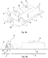
- Figs. 9A and 9B depict a conventional air-conditioning assembly including a compressor 5, a gas cooler/condenser heat exchanger 4, an expansion valve 12, an evaporator heat exchanger 3 and pipes 9, 10, 11 that connect sequentially the components creating a closed circuit for a refrigerant circulating through these components and being sequentially heated and cooled.
- Fans 6, 14, e.g. blowers or other means to move air through respective heat exchangers, are provided to transfer heat from the exemplary passenger compartment to the air conditioner and release is from there to an outside.
- Fig. 9A For simplicity in the description of the main functionalities of a vehicle air conditioner, two zones are defined in Fig. 9A , the zone 1 where the evaporator heat exchanger 3 is located (hereinafter referred to as the evaporator section 1) and the zone 2 where the gas cooler/condenser heat exchanger 4 is located (hereinafter referred to as the condenser section 2).
- the compressor 5 can be located in either one of the two zones or out of them.
- the evaporator section 1 and the condenser section 2 may be separated by a thermal isolation 16 (e.g. a wall) to thermally decouple hot components of the condenser section 2 from cool components in the evaporator section 1. Moreover such barrier may prevent any interference between the airflow moved by the blower 6 and the fan 14.
- the evaporator section 1 may include the evaporator heat exchanger 3, at least one fan 6 and a water collector 15, whereas the condenser section 2 includes at least the gas cooler/condenser heat exchanger 4 and the compressor 5 and is configured to carry away heat from the refrigerant during its condensation to an outside via the fan 14.
- the evaporator heat exchanger 3 is connected to the compressor 5, which is connected to the gas cooler/condenser heat exchanger 4, which in turn is connected to the expansion valve 12 and after that again to the evaporator heat exchanger 3 to close the circuit.
- the evaporator heat exchanger 3 evaporates a cooled refrigerant by absorbing heat from the surrounding (the passenger compartment) by using the fan 6. After being evaporated, the refrigerant is transferred as gas via a compressor suction line 9 to the compressor 5, where the gaseous refrigerant is compressed and thus heated.
- the refrigerant flows into the compressor discharge line 10, connecting the compressor outlet and condenser inlet, and enters the gas cooler/condenser heat exchanger 4, where the pressurized hot refrigerant is cooled and eventually partly or fully condensed using the fan(s) 14.
- the refrigerant is only cooled or the refrigerant is cooled and condensed (partly or fully).
- the "condenser heat exchanger” may act only as "gas cooler", because the refrigerant does not reach the condensation inside such heat exchanger. It stays in the gaseous form and it is simply cooled down.
- the one or more fans 14 at the condenser section 2 force outdoor air through the condenser heat exchanger 4 to cool down the refrigerant flowing inside the condenser.
- the refrigerant flows inside the liquid line 11, connecting the condenser outlet and an expansion valve inlet, until it reaches the expansion valve 12 where it is laminated and decompressed, and thus further cooled.
- the valve 12 After the valve 12, the refrigerant enters the evaporator heat exchanger 3 and begins another cycle. All components can be arranged inside a frame, which serves as an envelope of the vehicle air conditioner.
- Such frame can have a bottom part, formed by metal sheets 13.
- the one or more fans 6 at the evaporator section 1 force a certain quantity of air coming from the compartment (hereinafter referred to as indoor air) together with a certain quantity of outdoor air (which can also be equal to zero) through the evaporator heat exchanger 3.
- Indoor air a certain quantity of air coming from the compartment
- outdoor air which can also be equal to zero
- Heat is removed from the air stream and transferred to the refrigerant, flowing inside the heat exchanger 3, to evaporate it.
- this process can cause water condensation 7 on heat exchanger's surface. This water 8 is generally drained out of the system and wasted.
- the gas cooler/condenser heat exchanger 4 has to reject all the heat coming from the evaporator 3 and the compressor 5 and is thus usually the largest heat exchanger in the system. Attempts to reduce the size of this heat exchanger 4 can result in decreasing system cooling capacity and energy efficiency. Therefore, any mean to improve the heat dissipation in such component - keeping its size and weight within reasonable values - is of particular interest. It would reduce the energy needed by the air conditioner and does not increase the energy needed to move the system (traction energy consumption).
- Water stored in the tank tends to reach thermal equilibrium with the environment and with time can easily reach temperatures between 25 and 45°C, which are ideal for organisms like Legionella to grow and multiply. If this water is sprayed at the condenser section when an exemplary train (or another vehicle) is inside tunnels and/or stopped at station platforms, there is the risk of water droplets reaching passengers nearby the train.
- the present invention relates to a system for a vehicle air conditioner or an HVAC unit.
- the air conditioner or the HVAC unit comprises an evaporator section for evaporating a refrigerant while possibly generating condensation water and a condenser section for cooling and eventually condensing at least part of the refrigerant.
- the system includes a flow arrangement for allowing condensation water to flow from the evaporator section to the condenser section and means for transferring heat from at least a part of the condenser section to the condensation water, thereby improving the cooling of the refrigerant in the condenser section.
- the condenser section may be defined as the area where heat is transferred to the surrounding (warm or hot portion).
- the evaporator section may be defined as the area where heat is taken from the surrounding (cool portion of the air conditioner). Both sections are typically separated by a thermally isolating wall to thermally decouple both sections.
- the flow of the condensation water shall be arranged so that the condensation water flows freely without the aid of a dedicated pump or another device for driving the flow.
- the flow arrangement can include at least one pipe or a line or a channel or a system thereof.
- the refrigerant can be any working fluid or coolant (liquid or gaseous or a mixture thereof) to be used in an air conditioner as heat carrier.
- the evaporator section comprises an evaporator heat exchanger, an evaporator tray for collecting the condensation water generated by the evaporator heat exchanger and an evaporator fan for supplying cooled air
- the condenser section includes at least one condenser fan.
- the flow arrangement may provide a flow path connecting the evaporator tray with at least one component of the condenser section, wherein along the flow path (e.g. a pipe) the condensation water is driven by at least one of the following: a height difference (thus gravity driven), a differential pressure created between the condenser section and the evaporator section.
- the differential pressure may be caused by at least an evaporator fan and/or the at least one condenser fan.
- the condenser fan and/or the evaporator fan may increase a differential pressure between the condenser section and the evaporator section which can be used to support the flow of the condensation water towards the condenser section.
- the air conditioner or the HVAC unit may comprise a compressor and an expansion valve. Then, the flow arrangement may be configured to bring the condensation water into a direct contract with at least one part arranged, in respect to the (circulating) refrigerant, downstream of the compressor and upstream of the expansion valve.
- the at least one part includes one or more of the following: a (compressor) discharge line, a gas cooler/condenser heat exchanger, a condenser liquid line, a condenser tray or at least a part thereof.
- the at least one part in (part of) the compressor discharge line being at least one of the following: a connecting pipe, a finned tube, a series of pipes, a multichannel pipe.
- the at least one part includes (part of) a condenser liquid line being at least one of the following line types: a connecting pipe, a finned tube, a series of pipes, a multichannel pipe.
- the vehicle air conditioner or the HVAC unit may be supported by at least one structural frame member. Then, the at least one part may be integrated in the at least one structural frame member.
- the step of carrying condensation water includes establishing a gravity driven flow of the condensation water and/or establishing pressure-driven flow of the condensation water.
- the pressure driven flow may be established by using an evaporator fan which is upstream of the evaporator heat exchanger and/or a condenser fan which is downstream of the gas cooler/condenser heat exchanger.
- At least some of the aforementioned problems are mitigated by bringing water condensate originated in the evaporator heat exchanger in direct contact to any part of the gas cooler/condenser heat exchanger, including the discharge line(s) and/or the liquid line(s).
- Water condensate is usually at lower temperature than the refrigerant flowing inside the gas cooler/condenser heat exchanger and the condenser connecting lines and is therefore able to cool down the refrigerant.
- an adequate contact surface is disposed between water and condenser lines, water can evaporate, further cooling down the refrigerant.
- embodiments of the present invention provide means to improve the heat dissipation of the gas cooler/condenser heat exchanger, increasing cooling system capacity and/or system energy efficiency, without a significant increase of the heat exchanger size and weight.
- the following description of the exemplary embodiments illustrates main features of the present invention: how the condensate water shown in Fig. 9A (originated in the evaporator section 1) can be transferred to the condenser section 2 and how this water can be used in the condenser section 2 to improve heat dissipation.
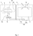
- Fig. 1 illustrates a system 100 according to an embodiment of the present invention, wherein the vehicle air-conditioner comprises an evaporator section 1 and a condenser section 2 which are thermally isolated by an exemplary wall 16.
- the evaporator section 1 comprises an evaporator heat exchanger 3, one or more evaporator fans 6, 61 and an evaporator tray 15.
- the evaporator fans 6, 61 can be arranged upstream of the evaporator heat exchanger 3 (i.e. the fan 61) or downstream of the evaporator heat exchanger 3 (i.e. the fan 6) so that the evaporator fans 6, 61 can push the air through the evaporator heat exchanger 3 (e.g.
- evaporator water tray a condensation water tray which is collected by the evaporator tray 15 under the evaporator heat exchanger 3 (hereinafter referred to as evaporator water tray).
- the condenser section 2 includes at least one condenser fan 14 and the gas cooler/condenser heat exchanger 4.
- the wall 16 avoids air transfer between the evaporator and the condenser section 1, 2.
- the use of a pump can be avoided provided the tray 15 is higher compared to the height of the drainage pipe outlet. In particular, there should be a sufficient height difference to promote gravity-driven water flow.
- a flow arrangement 110 (drainage pipe), which in the simplest case represents one or more pipes, is arranged between the evaporator section 1 and the condenser section 2 to bring the condensation water 115 from the evaporator section 1 to the condenser section 2.
- a flow arrangement 110 drainage pipe
- In the condenser section 2 means for transferring heat 120 are provided to cool down at least one component of the condenser section 2 by using the condensation water 115.
- the water 115 shall flow without a dedicated pump arranged along the flow path 110.
- the condensation water 115 can flow to the condenser section 2 only due to the height difference between the evaporator tray 15 and the means for transferring heat 120 in the condenser section 2.
- the flow of the condensation water 115 can also be driven due to a differential pressure difference between the evaporator section 1 and the condenser section 2 because the evaporator fans 6, 61 blow air out of the evaporator section 1.
- the upstream fan 61 generates an increased pressure within the evaporator section 1
- the condenser fan 14 sucks air out of the condenser section 2 and thus decreases the pressure inside the condenser section 2. Therefore, the pressure in the condenser section 2 may become sufficiently lower compared to the pressure in the evaporator section 1.
- this differential pressure may be used to drive the water flow from the evaporator section 1 to the condenser section 2.
- the evaporator fan 61 upstream from evaporator heat exchanger 3 is sufficiently strong to pressurize the evaporator water tray zone to promote the water flow in the drainage pipe 110.
- Fig. 2 depicts overview on the exemplary vehicle air conditioner with the evaporator heat exchanger 3, the gas cooler/condenser heat exchanger 4 arranged on a support member 13 (for example a metal sheet).
- the evaporator heat exchanger 3 is connected via a compressor suction line 9 to a compressor 5.
- the compressor 5 is connected to the condenser heat exchanger 4 via a compressor discharge line 10.
- the gas cooler/condenser heat exchanger 4 is connected to an expansion valve 12 via a condenser liquid line 11, and the expansion valve 12 is connected again to the compressor heat exchanger 3.
- the compressor heat exchanger 3 belongs to the evaporator section 1, whereas the compressor 5 and the gas cooler/condenser heat exchanger 4 belong here to the condenser section 2. However, the compressor 5 can also be located in the evaporator section 1 or out of both the evaporator and condenser section.
- the evaporator tray 15 is formed to collect the condensation water 115 (not shown in Fig. 2 ). This water 115 is transferred to a condenser tray 19 under the gas cooler/condenser heat exchanger 4 via the drainage pipe 110. Again, the condensation water 115 may be driven to the condenser tray 19 by gravity (i.e.
- the water is transferred from the evaporator section 1 to the condenser section 2 by any of the methods described with Fig. 1 .
- the condenser tray 19 is at least part of the means for transferring heat 120.
- the compressor 5 is configured to compress the evaporated refrigerant coming from the evaporator heat exchanger 3 via the compressor suction line 9. After compressing the gaseous refrigerant, the hot compressed refrigerant is carried to the gas cooler/condenser heat exchanger 4 via the compressor discharge line 10. In the gas cooler/condenser heat exchanger 4, heat from the compressed refrigerant is transferred to the surrounding, thereby cooling the pressurized refrigerant which depending on the working conditions of the cycle can either stays in gaseous form or at least partly condenses and is afterwards carried by the condenser liquid line 11 to the expansion valve 12. In the expansion valve 12, the pressurized refrigerant is decompressed and thus further cooled. Finally, the decompressed liquid refrigerant is evaporated in the evaporator heat exchanger 3 by taking up heat from the surrounding (which is thus cooled).
- the condensate water 115 is brought in direct contact with the gas cooler/condenser heat exchanger 4 and flows to the condenser tray 19 disposed under the gas cooler/condenser heat exchanger 4.
- a lower section of the gas cooler/condenser heat exchanger 4 is wetted so that the heat transfer dissipation is increased in this section.
- the condensation water overflows, for example, from the top of the condenser tray 19 and drops onto frame bottom 13 and may be drained out of the unit in the condenser section 2.
- Fig. 3 depicts another embodiment according to the present invention, wherein the condensation water 115 (not shown in Fig. 3 ) is transferred from the evaporator tray 15 (the corresponding drainage pipe 110 is not shown) to another tray 20 disposed under the compressor discharge line 10. Therefore, the condensation water 115 gets into direct contact to the compressor discharge line 10 and thus decreases the temperature of the compressed refrigerant inside the compressor discharge line 10 before the refrigerant enters the gas cooler/condenser heat exchanger 4.
- the other tray 20 is the means for transferring heat 120.
- condenser tray 19 may be present to receive part of the condensation water 115 to cool down the gas cooler/condenser heat exchanger 4.
- condensation water 115 may be transferred from the evaporator section 1 to the condenser section 2 by any of the methods described previously (driven by gravity or by differential pressure).
- the compressor discharge line 10 can be a simple connecting pipe as depicted in the enlarged view, or can be modified to enhance the heat transfer between air and the piping and/or water and the piping. Possible ways of modifying the discharge line 10 to improve heat transfer will be described with the next figures.
- Fig. 4 depicts an embodiment, wherein the compressor discharge line 10 includes fins 21, thereby improving the heat exchange between the condensation water 115 within the other tray 20 and the compressor discharge line 10.
- the fins 21 and the tray 20 are the means for transferring heat 120 and the drainage pipe 110 is (part of) the flow arrangement 110.
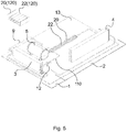
- Fig. 5 depicts an embodiment, wherein the compressor discharge line 10 is split into a plurality of pipes 22 which are arranged along the tray 20 and get into direct contact with the condensation water 115 within the other tray 20. As a result, the contact area between air and/or water and the compressor discharge line 10 is increased.
- the pipes 22 together with the tray 20 represent the means for transferring heat 120.
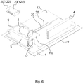
- FIG. 6 Yet another embodiment is shown in Fig. 6 , wherein the compressor discharge line 10 is split in a multichannel pipe 23.
- the multichannel pipe 23 may be formed as an array of pipes which are distributed horizontally and vertically and which are again in direct contact with the condensation water 115 in the tray 20.
- the trays 20 can be open or closed and that the compressor discharge line 10 can be surrounded completely by the condensation water 115.
- the multichannel pipes 23 together with the tray 20 represent the means for transferring heat 120 and the drainage pipe 110 is included in the flow arrangement 110.
- multichannel pipe 23 (and similarly also the plurality of pipes 22 and fins 21) may comprise copper or aluminum and may be formed as extrusion or other means to create a tube with several channels inside.
- Fig. 7 depicts an embodiment, wherein the compressor discharge line 10 with or without fins 21 or being arranged as a plurality of pipes 22 or as a multi-channel pipe 23 is formed at least partly within a support structure of the vehicle air conditioner (for example the bottom beams 24) which provide a reinforcement of the support member 13.
- the multichannel pipes 23 together with the tray 20 represent the means for transferring heat 120.
- the same setup may be implemented for the condenser liquid line 11, which may likewise be cooled by the condensation water 115.
- the multichannel pipe 23, for example, can be integrated as structural member of the vehicle air conditioner frame. In this way, the compressor discharge line 10 and/or the condenser liquid line 11 may serve multiple purposes:
- the multichannel 23 can be connected to other structural members of the vehicle air conditioner frame, such as bottom beams 24 and/or fixed to the frame bottom 13 by soldering or riveting to increase bottom metal sheet stiffness.
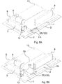
- Fig. 8A and 8B depict an embodiment, wherein the condenser liquid line 11 is cooled by the condensation water.
- the condenser liquid line 11 is cooled by the condensation water.
- same arrangements as described in combination in Figs. 3 to 6 can be used.
- the condensate water 115 is brought in direct contact with the condenser liquid line 11, which may be split into a plurality of pipes 25 (representing part of the means for transferring heat 120).
- the condenser liquid line 11 is split into multiple pipes 25 to enhance heat transfer. Any other arrangement similar to the ones shown for the compressor discharge line 10 in Fig 4 to Fig.7 can be used to increase the heat transfer surface (finned tube, multi channels etc.).
- Fig. 8B the setups of Fig. 2 and Fig. 8A , are combined together.
- the condensate water 115 is thus brought first in contact with the condenser liquid line 11/multiple pipes 25 and subsequently with the bottom section of the gas cooler/condenser heat exchanger 4.
- the condensation water 115 may again be transferred from the evaporator section 1 to the condenser section 2 by any of the methods described in Fig 1 (driven by gravity and/or by a differential pressure).
- the various possibilities to use the condensation water 115 to cool down at least one of the components arranged in the condensation section 2 can be combined with each other.
- the condensation water 115 can be split in accordance with the respective heat in the condensation section 2.
- the compressor discharge line 10 having the highest temperature may receive most of the condensation water 115, wherein the gas cooler/condenser heat exchanger 4 and the liquid lines 11 may receive less condensation water 115 from the evaporator tray 15 in the evaporation section 10. But this may be setup as desired. Also, there is no restriction for the order, i.e. which component receives first the condensation water 115 and which at last.
- a vehicle air conditioner where condensate water 115 originated in the evaporator section 1 is transferred to condenser section 2.
- the water 115 may be transferred from the evaporator to the condenser section 1, 2 by means of a height difference between water evaporator tray and drainage pipe outlet 110, or by differential pressure created between the evaporator and the condenser section 2 by a fan 61 upstream the evaporator tray 15, or by a combination of two or more of the aforementioned methods.
- the water 115 may be transferred to the condenser section 2 and brought into direct contact with any part of the circuit which is carrying refrigerant within the compressor outlet and the expansion valve 12.
- This portion of the circuit comprises, but is not limited to, the discharge line 10, the gas cooler/condenser heat exchanger 4 and the condenser liquid line 11.
- the water 115 may be brought into direct contact with the compressor discharge line 10 and the discharge line 10 is either a simple connecting pipe, or a finned tube 21, or a series of pipes 22 or a multichannel pipe 23.
- the water 115 may be brought into direct contact with the condenser liquid line 11 and the liquid line 11 is either a simple connecting pipe, or a finned tube, or a series of pipes or a multichannel pipe.
- the water 115 may be brought into direct contact with gas cooler/condenser heat exchanger 4.
- the water 115 may be brought into direct contact with compressor discharge line 10, the discharge line 10 is a pipe or a multichannel pipe 23 and the discharge line 10 is integrated as a structural member of the vehicle air conditioner frame.
- the water 115 may be brought into direct contact with condenser liquid line 11, the liquid line 11 is a pipe or a multichannel pipe and the liquid line is integrated as a structural member of the vehicle air conditioner frame.
Landscapes
- Engineering & Computer Science (AREA)
- Mechanical Engineering (AREA)
- Chemical & Material Sciences (AREA)
- Combustion & Propulsion (AREA)
- General Engineering & Computer Science (AREA)
- Physics & Mathematics (AREA)
- Thermal Sciences (AREA)
- Air-Conditioning For Vehicles (AREA)
Abstract
Description
- The present invention relates to a system and a method for a vehicle air conditioner or a HVAC unit (heating ventilation air-conditioning unit) and, in particular, to a water-cooled condenser for a vehicle air conditioner and to a method to bring water condensate formed on an evaporator coil to a condenser section.
- Vehicle air conditioners are able to maintain certain conditions of temperature, humidity and air quality in a specific compartment, like a passenger compartment in a train or in a car.
-
Figs. 9A and 9B depict a conventional air-conditioning assembly including acompressor 5, a gas cooler/condenser heat exchanger 4, anexpansion valve 12, anevaporator heat exchanger 3 andpipes Fans - For simplicity in the description of the main functionalities of a vehicle air conditioner, two zones are defined in
Fig. 9A , thezone 1 where theevaporator heat exchanger 3 is located (hereinafter referred to as the evaporator section 1) and thezone 2 where the gas cooler/condenser heat exchanger 4 is located (hereinafter referred to as the condenser section 2). Thecompressor 5 can be located in either one of the two zones or out of them. - As shown in
Fig. 9B theevaporator section 1 and thecondenser section 2 may be separated by a thermal isolation 16 (e.g. a wall) to thermally decouple hot components of thecondenser section 2 from cool components in theevaporator section 1. Moreover such barrier may prevent any interference between the airflow moved by theblower 6 and thefan 14. Theevaporator section 1 may include theevaporator heat exchanger 3, at least onefan 6 and awater collector 15, whereas thecondenser section 2 includes at least the gas cooler/condenser heat exchanger 4 and thecompressor 5 and is configured to carry away heat from the refrigerant during its condensation to an outside via thefan 14. - The
evaporator heat exchanger 3 is connected to thecompressor 5, which is connected to the gas cooler/condenser heat exchanger 4, which in turn is connected to theexpansion valve 12 and after that again to theevaporator heat exchanger 3 to close the circuit. Theevaporator heat exchanger 3 evaporates a cooled refrigerant by absorbing heat from the surrounding (the passenger compartment) by using thefan 6. After being evaporated, the refrigerant is transferred as gas via acompressor suction line 9 to thecompressor 5, where the gaseous refrigerant is compressed and thus heated. At the compressor outlet the refrigerant flows into thecompressor discharge line 10, connecting the compressor outlet and condenser inlet, and enters the gas cooler/condenser heat exchanger 4, where the pressurized hot refrigerant is cooled and eventually partly or fully condensed using the fan(s) 14. In the gas cooler/condenser heat exchanger, the refrigerant is only cooled or the refrigerant is cooled and condensed (partly or fully). For example, in some specific HVAC systems, like the ones using CO2 as a refrigerant, the "condenser heat exchanger" may act only as "gas cooler", because the refrigerant does not reach the condensation inside such heat exchanger. It stays in the gaseous form and it is simply cooled down. - The one or
more fans 14 at thecondenser section 2 force outdoor air through thecondenser heat exchanger 4 to cool down the refrigerant flowing inside the condenser. At a condenser outlet the refrigerant flows inside theliquid line 11, connecting the condenser outlet and an expansion valve inlet, until it reaches theexpansion valve 12 where it is laminated and decompressed, and thus further cooled. After thevalve 12, the refrigerant enters theevaporator heat exchanger 3 and begins another cycle. All components can be arranged inside a frame, which serves as an envelope of the vehicle air conditioner. Such frame can have a bottom part, formed bymetal sheets 13. - If for example heat has to be removed from passenger's compartment, the one or
more fans 6 at theevaporator section 1 force a certain quantity of air coming from the compartment (hereinafter referred to as indoor air) together with a certain quantity of outdoor air (which can also be equal to zero) through theevaporator heat exchanger 3. Heat is removed from the air stream and transferred to the refrigerant, flowing inside theheat exchanger 3, to evaporate it. Depending on air humidity and temperature, as well as surface temperature of theevaporator heat exchanger 3, this process can cause water condensation 7 on heat exchanger's surface. Thiswater 8 is generally drained out of the system and wasted. - On the other hand, the gas cooler/
condenser heat exchanger 4 has to reject all the heat coming from theevaporator 3 and thecompressor 5 and is thus usually the largest heat exchanger in the system. Attempts to reduce the size of thisheat exchanger 4 can result in decreasing system cooling capacity and energy efficiency. Therefore, any mean to improve the heat dissipation in such component - keeping its size and weight within reasonable values - is of particular interest. It would reduce the energy needed by the air conditioner and does not increase the energy needed to move the system (traction energy consumption). - One possibility to improve the performance of a condenser heat exchanger is to use the water condensate formed in the evaporator heat exchanger and wet the surface of the condenser heat exchanger. One possibility is proposed in
US 2010/307176 A , where water coming from the evaporator is collected and stored in a water tank. Subsequently, this water is pumped and sprayed through a nozzle placed onto the fins of the condenser coil. - Another attempt to make use of water condensate is described in
CN 104748348 A , where the condensation water is collected in a water tray below the evaporator. Again, a pump takes the water from the water tray and forces it through a liquid to liquid heat exchanger to cool a liquid line coming from the condenser coil. After this, the water is pumped above the condenser coil and wets the condenser coil. - While these solutions achieve an improvement of the heat dissipation process at the condenser section, there are still remaining drawbacks in terms of reliability and maintainability. First, a pump is needed to move water from the evaporator zone. This is an additional component that in case of a failure, would stop bringing water to the condenser section losing their benefits. Moreover, a pump failure can result in the evaporator tray not being drained. Also, the spray nozzle is subjected to a possible clogging and therefore needs periodic maintenance. Likewise, a tank introduces additional weight with the potential risk of bacteria formation in stagnant water. Water stored in the tank tends to reach thermal equilibrium with the environment and with time can easily reach temperatures between 25 and 45°C, which are ideal for organisms like Legionella to grow and multiply. If this water is sprayed at the condenser section when an exemplary train (or another vehicle) is inside tunnels and/or stopped at station platforms, there is the risk of water droplets reaching passengers nearby the train.
- According to these considerations, it is desirable to still make use of water condensate, as a matter to improve heat rejection in the condenser section, but at the same time to minimize or to eliminate the aforementioned drawbacks.
- At least some of these problems of the conventional device are overcome by a system of
claim 1 or a method according toclaim 9. The dependent claims refer to further advantageous realizations of the subject matter of the independent claims. - The present invention relates to a system for a vehicle air conditioner or an HVAC unit. The air conditioner or the HVAC unit comprises an evaporator section for evaporating a refrigerant while possibly generating condensation water and a condenser section for cooling and eventually condensing at least part of the refrigerant. The system includes a flow arrangement for allowing condensation water to flow from the evaporator section to the condenser section and means for transferring heat from at least a part of the condenser section to the condensation water, thereby improving the cooling of the refrigerant in the condenser section.
- The condenser section may be defined as the area where heat is transferred to the surrounding (warm or hot portion). The evaporator section may be defined as the area where heat is taken from the surrounding (cool portion of the air conditioner). Both sections are typically separated by a thermally isolating wall to thermally decouple both sections. The flow of the condensation water shall be arranged so that the condensation water flows freely without the aid of a dedicated pump or another device for driving the flow. The flow arrangement can include at least one pipe or a line or a channel or a system thereof. The refrigerant can be any working fluid or coolant (liquid or gaseous or a mixture thereof) to be used in an air conditioner as heat carrier.
- Optionally, the evaporator section comprises an evaporator heat exchanger, an evaporator tray for collecting the condensation water generated by the evaporator heat exchanger and an evaporator fan for supplying cooled air, the condenser section includes at least one condenser fan. Then, the flow arrangement may provide a flow path connecting the evaporator tray with at least one component of the condenser section, wherein along the flow path (e.g. a pipe) the condensation water is driven by at least one of the following: a height difference (thus gravity driven), a differential pressure created between the condenser section and the evaporator section. The differential pressure may be caused by at least an evaporator fan and/or the at least one condenser fan. For example, the condenser fan and/or the evaporator fan may increase a differential pressure between the condenser section and the evaporator section which can be used to support the flow of the condensation water towards the condenser section.
- The air conditioner or the HVAC unit may comprise a compressor and an expansion valve. Then, the flow arrangement may be configured to bring the condensation water into a direct contract with at least one part arranged, in respect to the (circulating) refrigerant, downstream of the compressor and upstream of the expansion valve.
- Optionally, the at least one part includes one or more of the following: a (compressor) discharge line, a gas cooler/condenser heat exchanger, a condenser liquid line, a condenser tray or at least a part thereof.
- Optionally, the at least one part in (part of) the compressor discharge line being at least one of the following: a connecting pipe, a finned tube, a series of pipes, a multichannel pipe.
- Optionally, the at least one part includes (part of) a condenser liquid line being at least one of the following line types: a connecting pipe, a finned tube, a series of pipes, a multichannel pipe.
- The vehicle air conditioner or the HVAC unit may be supported by at least one structural frame member. Then, the at least one part may be integrated in the at least one structural frame member.
- Further embodiments relate to a vehicle, in particular to a railway vehicle, with an air conditioner or an HVAC unit, wherein the air conditioner or the HVAC unit includes a system as defined before.
- Further embodiments relate to a method for supporting a condensation and/or a cooling of a refrigerant in a condenser section of a vehicle air conditioner, the air conditioner further comprising an evaporator section for evaporating the refrigerant while possibly generating the condensation water. The method includes:
- carrying condensation water freely from the evaporator section to the condenser section; and
- transferring heat from at least a part of the condenser section to the condensation water, thereby supporting the condensation and/or the cooling of the refrigerant in the condenser section.
- For example, the step of carrying condensation water includes establishing a gravity driven flow of the condensation water and/or establishing pressure-driven flow of the condensation water. The pressure driven flow may be established by using an evaporator fan which is upstream of the evaporator heat exchanger and/or a condenser fan which is downstream of the gas cooler/condenser heat exchanger.
- At least some of the aforementioned problems are mitigated by bringing water condensate originated in the evaporator heat exchanger in direct contact to any part of the gas cooler/condenser heat exchanger, including the discharge line(s) and/or the liquid line(s). Water condensate is usually at lower temperature than the refrigerant flowing inside the gas cooler/condenser heat exchanger and the condenser connecting lines and is therefore able to cool down the refrigerant. Moreover, if an adequate contact surface is disposed between water and condenser lines, water can evaporate, further cooling down the refrigerant.
- Therefore, embodiments of the present invention provide means to improve the heat dissipation of the gas cooler/condenser heat exchanger, increasing cooling system capacity and/or system energy efficiency, without a significant increase of the heat exchanger size and weight.
- Some examples of the systems and/or methods will be described in the following by way of examples only, and with respect to the accompanying figures, in which:
- Fig. 1
- depicts a system according to an embodiment of the present invention.
- Fig. 2
- depicts an overview on the vehicle air conditioner according another embodiment.
- Fig. 3
- depicts an overview on the vehicle air conditioner according yet another embodiment.
- Fig. 4
- depicts an overview on the vehicle air conditioner according yet another embodiment.
- Fig. 5
- depicts an overview on the vehicle air conditioner according yet another embodiment.
- Fig. 6
- depicts an overview on the vehicle air conditioner according yet another embodiment.
- Fig. 7
- depicts an overview on the vehicle air conditioner according yet another embodiment.
- Fig. 8A,8B
- depict overviews on the vehicle air conditioners according to further embodiments.
- Fig. 9A,9B
- depict a side view and an overview on a conventional vehicle air conditioner.
- The following description of the exemplary embodiments illustrates main features of the present invention: how the condensate water shown in
Fig. 9A (originated in the evaporator section 1) can be transferred to thecondenser section 2 and how this water can be used in thecondenser section 2 to improve heat dissipation. -
Fig. 1 illustrates asystem 100 according to an embodiment of the present invention, wherein the vehicle air-conditioner comprises anevaporator section 1 and acondenser section 2 which are thermally isolated by anexemplary wall 16. Theevaporator section 1 comprises anevaporator heat exchanger 3, one or moreevaporator fans evaporator tray 15. Theevaporator fans evaporator fans evaporator heat exchanger 3 resulting inpossible condensation water 115 which is collected by theevaporator tray 15 under the evaporator heat exchanger 3 (hereinafter referred to as evaporator water tray). - The
condenser section 2 includes at least onecondenser fan 14 and the gas cooler/condenser heat exchanger 4. Thewall 16 avoids air transfer between the evaporator and thecondenser section water 115 from theevaporator section 1 to thecondenser section 2, the use of a pump can be avoided provided thetray 15 is higher compared to the height of the drainage pipe outlet. In particular, there should be a sufficient height difference to promote gravity-driven water flow. - According to embodiments of the present invention, a flow arrangement 110 (drainage pipe), which in the simplest case represents one or more pipes, is arranged between the
evaporator section 1 and thecondenser section 2 to bring thecondensation water 115 from theevaporator section 1 to thecondenser section 2. In thecondenser section 2 means for transferringheat 120 are provided to cool down at least one component of thecondenser section 2 by using thecondensation water 115. - According to embodiments of the present invention the
water 115 shall flow without a dedicated pump arranged along theflow path 110. For example, thecondensation water 115 can flow to thecondenser section 2 only due to the height difference between theevaporator tray 15 and the means for transferringheat 120 in thecondenser section 2. - According to another embodiment, the flow of the
condensation water 115 can also be driven due to a differential pressure difference between theevaporator section 1 and thecondenser section 2 because theevaporator fans evaporator section 1. For example, theupstream fan 61 generates an increased pressure within theevaporator section 1, whereas thecondenser fan 14 sucks air out of thecondenser section 2 and thus decreases the pressure inside thecondenser section 2. Therefore, the pressure in thecondenser section 2 may become sufficiently lower compared to the pressure in theevaporator section 1. According to embodiments, this differential pressure may be used to drive the water flow from theevaporator section 1 to thecondenser section 2. To increase this effect, theevaporator fan 61 upstream fromevaporator heat exchanger 3 is sufficiently strong to pressurize the evaporator water tray zone to promote the water flow in thedrainage pipe 110. - It is understood that any of the designs related to the fans (
upstream fan 61,downstream fan 6 or both) and height differences can be combined, to ensure that water drainage takes place at any working conditions. -
Fig. 2 depicts overview on the exemplary vehicle air conditioner with theevaporator heat exchanger 3, the gas cooler/condenser heat exchanger 4 arranged on a support member 13 (for example a metal sheet). Theevaporator heat exchanger 3 is connected via acompressor suction line 9 to acompressor 5. Thecompressor 5 is connected to thecondenser heat exchanger 4 via acompressor discharge line 10. The gas cooler/condenser heat exchanger 4 is connected to anexpansion valve 12 via acondenser liquid line 11, and theexpansion valve 12 is connected again to thecompressor heat exchanger 3. - The
compressor heat exchanger 3 belongs to theevaporator section 1, whereas thecompressor 5 and the gas cooler/condenser heat exchanger 4 belong here to thecondenser section 2. However, thecompressor 5 can also be located in theevaporator section 1 or out of both the evaporator and condenser section In addition, below theevaporator heat exchanger 3 theevaporator tray 15 is formed to collect the condensation water 115 (not shown inFig. 2 ). Thiswater 115 is transferred to acondenser tray 19 under the gas cooler/condenser heat exchanger 4 via thedrainage pipe 110. Again, thecondensation water 115 may be driven to thecondenser tray 19 by gravity (i.e. a height difference between bothtrays 15, 19) or via the differential pressure between theevaporator section 1 and thecondenser section 2. Thus, the water is transferred from theevaporator section 1 to thecondenser section 2 by any of the methods described withFig. 1 . In this embodiment thecondenser tray 19 is at least part of the means for transferringheat 120. - As for the conventional air conditioner, the
compressor 5 is configured to compress the evaporated refrigerant coming from theevaporator heat exchanger 3 via thecompressor suction line 9. After compressing the gaseous refrigerant, the hot compressed refrigerant is carried to the gas cooler/condenser heat exchanger 4 via thecompressor discharge line 10. In the gas cooler/condenser heat exchanger 4, heat from the compressed refrigerant is transferred to the surrounding, thereby cooling the pressurized refrigerant which depending on the working conditions of the cycle can either stays in gaseous form or at least partly condenses and is afterwards carried by thecondenser liquid line 11 to theexpansion valve 12. In theexpansion valve 12, the pressurized refrigerant is decompressed and thus further cooled. Finally, the decompressed liquid refrigerant is evaporated in theevaporator heat exchanger 3 by taking up heat from the surrounding (which is thus cooled). - In this exemplary embodiment the
condensate water 115 is brought in direct contact with the gas cooler/condenser heat exchanger 4 and flows to thecondenser tray 19 disposed under the gas cooler/condenser heat exchanger 4. Hence, a lower section of the gas cooler/condenser heat exchanger 4 is wetted so that the heat transfer dissipation is increased in this section. After being heated, the condensation water overflows, for example, from the top of thecondenser tray 19 and drops onto frame bottom 13 and may be drained out of the unit in thecondenser section 2. -
Fig. 3 depicts another embodiment according to the present invention, wherein the condensation water 115 (not shown inFig. 3 ) is transferred from the evaporator tray 15 (thecorresponding drainage pipe 110 is not shown) to anothertray 20 disposed under thecompressor discharge line 10. Therefore, thecondensation water 115 gets into direct contact to thecompressor discharge line 10 and thus decreases the temperature of the compressed refrigerant inside thecompressor discharge line 10 before the refrigerant enters the gas cooler/condenser heat exchanger 4. In this embodiment theother tray 20 is the means for transferringheat 120. - All other components are arranged in the same way as in
Fig. 1 orFig. 2 so that there is no need to repeat their description. Although not shown, also in this embodiment thecondenser tray 19 may be present to receive part of thecondensation water 115 to cool down the gas cooler/condenser heat exchanger 4. - Again, the
condensation water 115 may be transferred from theevaporator section 1 to thecondenser section 2 by any of the methods described previously (driven by gravity or by differential pressure). - The
compressor discharge line 10 can be a simple connecting pipe as depicted in the enlarged view, or can be modified to enhance the heat transfer between air and the piping and/or water and the piping. Possible ways of modifying thedischarge line 10 to improve heat transfer will be described with the next figures. -
Fig. 4 depicts an embodiment, wherein thecompressor discharge line 10 includesfins 21, thereby improving the heat exchange between thecondensation water 115 within theother tray 20 and thecompressor discharge line 10. In this embodiment thefins 21 and thetray 20 are the means for transferringheat 120 and thedrainage pipe 110 is (part of) theflow arrangement 110. -
Fig. 5 depicts an embodiment, wherein thecompressor discharge line 10 is split into a plurality ofpipes 22 which are arranged along thetray 20 and get into direct contact with thecondensation water 115 within theother tray 20. As a result, the contact area between air and/or water and thecompressor discharge line 10 is increased. In this embodiment thepipes 22 together with thetray 20 represent the means for transferringheat 120. - Yet another embodiment is shown in
Fig. 6 , wherein thecompressor discharge line 10 is split in amultichannel pipe 23. Themultichannel pipe 23 may be formed as an array of pipes which are distributed horizontally and vertically and which are again in direct contact with thecondensation water 115 in thetray 20. - It is understood that here and in the other embodiments, the
trays 20 can be open or closed and that thecompressor discharge line 10 can be surrounded completely by thecondensation water 115. In this embodiment themultichannel pipes 23 together with thetray 20 represent the means for transferringheat 120 and thedrainage pipe 110 is included in theflow arrangement 110. - In addition, the multichannel pipe 23 (and similarly also the plurality of
pipes 22 and fins 21) may comprise copper or aluminum and may be formed as extrusion or other means to create a tube with several channels inside. -
Fig. 7 depicts an embodiment, wherein thecompressor discharge line 10 with or withoutfins 21 or being arranged as a plurality ofpipes 22 or as amulti-channel pipe 23 is formed at least partly within a support structure of the vehicle air conditioner (for example the bottom beams 24) which provide a reinforcement of thesupport member 13. In this embodiment themultichannel pipes 23 together with thetray 20 represent the means for transferringheat 120. - The same setup may be implemented for the
condenser liquid line 11, which may likewise be cooled by thecondensation water 115. Themultichannel pipe 23, for example, can be integrated as structural member of the vehicle air conditioner frame. In this way, thecompressor discharge line 10 and/or thecondenser liquid line 11 may serve multiple purposes: - it carries the refrigerant from the
compressor 5 to thecondenser heat exchanger 4 or from there to theexpansion valve 12, - it cools down the refrigerant by exchanging heat with air and/or with water,
- it creates a
beam 23 that contributes to the structural reinforcement of the frame. - Furthermore, the multichannel 23 can be connected to other structural members of the vehicle air conditioner frame, such as bottom beams 24 and/or fixed to the frame bottom 13 by soldering or riveting to increase bottom metal sheet stiffness.
-
Fig. 8A and 8B depict an embodiment, wherein thecondenser liquid line 11 is cooled by the condensation water. For this, same arrangements as described in combination inFigs. 3 to 6 can be used. - In the embodiment illustrated in
Fig. 8A , thecondensate water 115 is brought in direct contact with thecondenser liquid line 11, which may be split into a plurality of pipes 25 (representing part of the means for transferring heat 120). Thecondenser liquid line 11 is split intomultiple pipes 25 to enhance heat transfer. Any other arrangement similar to the ones shown for thecompressor discharge line 10 inFig 4 to Fig.7 can be used to increase the heat transfer surface (finned tube, multi channels etc.). - For example, in the embodiment illustrated in
Fig. 8B , the setups ofFig. 2 andFig. 8A , are combined together. Thecondensate water 115 is thus brought first in contact with thecondenser liquid line 11/multiple pipes 25 and subsequently with the bottom section of the gas cooler/condenser heat exchanger 4. - Also for these embodiments, the
condensation water 115 may again be transferred from theevaporator section 1 to thecondenser section 2 by any of the methods described inFig 1 (driven by gravity and/or by a differential pressure). - It is understood that the various possibilities to use the
condensation water 115 to cool down at least one of the components arranged in thecondensation section 2 can be combined with each other. In addition, thecondensation water 115 can be split in accordance with the respective heat in thecondensation section 2. For example, thecompressor discharge line 10 having the highest temperature may receive most of thecondensation water 115, wherein the gas cooler/condenser heat exchanger 4 and theliquid lines 11 may receiveless condensation water 115 from theevaporator tray 15 in theevaporation section 10. But this may be setup as desired. Also, there is no restriction for the order, i.e. which component receives first thecondensation water 115 and which at last. - Advantageous embodiments relate, in particular, to the following subject matters:
A vehicle air conditioner, wherecondensate water 115 originated in theevaporator section 1 is transferred tocondenser section 2. - The
water 115 may be transferred from the evaporator to thecondenser section drainage pipe outlet 110, or by differential pressure created between the evaporator and thecondenser section 2 by afan 61 upstream theevaporator tray 15, or by a combination of two or more of the aforementioned methods. - The
water 115 may be transferred to thecondenser section 2 and brought into direct contact with any part of the circuit which is carrying refrigerant within the compressor outlet and theexpansion valve 12. This portion of the circuit comprises, but is not limited to, thedischarge line 10, the gas cooler/condenser heat exchanger 4 and thecondenser liquid line 11. - The
water 115 may be brought into direct contact with thecompressor discharge line 10 and thedischarge line 10 is either a simple connecting pipe, or afinned tube 21, or a series ofpipes 22 or amultichannel pipe 23. - The
water 115 may be brought into direct contact with thecondenser liquid line 11 and theliquid line 11 is either a simple connecting pipe, or a finned tube, or a series of pipes or a multichannel pipe. - The
water 115 may be brought into direct contact with gas cooler/condenser heat exchanger 4. - The
water 115 may be brought into direct contact withcompressor discharge line 10, thedischarge line 10 is a pipe or amultichannel pipe 23 and thedischarge line 10 is integrated as a structural member of the vehicle air conditioner frame. - The
water 115 may be brought into direct contact withcondenser liquid line 11, theliquid line 11 is a pipe or a multichannel pipe and the liquid line is integrated as a structural member of the vehicle air conditioner frame. - The description and drawings merely illustrate the principles of the disclosure. It will thus be appreciated that those skilled in the art will be able to devise various arrangements that, although not explicitly described or shown herein, embody the principles of the disclosure and are included within its scope.
- Furthermore, while each embodiment may stand on its own as a separate example, it is to be noted that in other embodiments the defined features can be combined differently, i.e. a particular feature descripted in one embodiment may also be realized in other embodiments. Such combinations are covered by the disclosure herein unless it is stated that a specific combination is not intended.
-
- 1
- evaporator section
- 2
- condenser section
- 3
- evaporator heat exchanger
- 4
- gas cooler/condenser heat exchanger
- 5
- compressor
- 6, 61
- evaporator fan
- 9
- compressor suction line
- 10
- compressor discharge line
- 11
- condenser liquid line
- 12
- expansion valve
- 13
- support member (metal sheet)
- 14
- condenser film
- 15
- evaporator tray
- 16
- thermal isolation/wall
- 19
- condenser tray
- 20
- another tray
- 21
- fins
- 22
- plurality of pipes
- 23
- multichannel pipe
- 24
- support structure/bottom beams
- 25
- plurality of liquid lines
- 110
- flow arrangement
- 115
- condensation water
- 120
- means for transferring heat
Claims (11)
- A system (100) for a vehicle air conditioner or an HVAC (heating, ventilation, air-conditioning) unit, the air conditioner or HVAC unit comprising an evaporator section (1) for evaporating a refrigerant while possibly generating condensation water and a condenser section (2) for condensing and/or cooling at least part of the refrigerant,
characterized by:- a flow arrangement (110) for allowing condensation water (115) to flow from the evaporator section (1) to the condenser section (2); and- means (120) for transferring heat from at least a part of the condenser section (2) to the condensation water (115), thereby improving the condensing and/or the cooling of the refrigerant in the condenser section (2). - The system (100) according to claim 1, wherein the evaporator section (1) comprises an evaporator heat exchanger (3), an evaporator tray (15) for collecting the condensation water (115) generated by the evaporator heat exchanger (3) and an evaporator fan (6, 61) for supplying cooled air, the condenser section (2) including at least one condenser fan (14)
characterized in that
the flow arrangement (110) provides a flow path connecting the evaporator tray (15) with at least one component of the condenser section (2), wherein along the flow path the condensation water is driven by at least one of the following: a height difference, a pump, a differential pressure created between the condenser section (2) and the evaporator section (2) by the evaporator fan (6, 61) and/or the evaporator fan (6, 61) combined with the at least one condenser fan (14) or the at least one condenser fan (14). - The system (100) according to claim 1 or claim 2, wherein the air conditioner or the HVAC unit comprises a compressor (5) and an expansion valve (12),
characterized in that
the flow arrangement (110) is configured to bring the condensation water (115) into a direct contact with at least one part (4, 10, 11, 19) arranged, in respect to the refrigerant, downstream the compressor (5) and upstream the expansion valve (12). - The system (100) according to claim 3,
characterized in that
the at least one part (4, 10, 11, 19) includes one or more of the following: a discharge line (10), a condenser heat exchanger (4), a condenser liquid line (11), a condenser tray (19) or at least a part thereof. - The system (100) according to claim 3 or claim 4,
characterized in that
the at least one part includes a compressor discharge line (10) being at least one of the following: a connecting pipe, a finned tube, a series of pipes, a multichannel pipe. - The system (100) according to claim 4 or claim 5,
characterized in that
the at least one part includes a condenser liquid line (11) being at least one of the following line types: a connecting pipe, a finned tube, a series of pipes, a multichannel pipe. - The system (100) according to one of claims 3 to 6, wherein the vehicle air conditioner or the HVAC unit is supported by at least one structural frame member,
characterized in that
the at least one part is integrated in the at least one structural frame member. - A vehicle, in particular a railway vehicle, with an air conditioner or an HVAC unit,
characterized in that
the air conditioner or the HVAC unit includes a system (100) according to one of the preceding claims. - A method for supporting a condensing and/or a cooling of a refrigerant in a condenser section (2) of a vehicle air conditioner or HVAC unit, the air conditioner or HVAC (heating, ventilation, air-conditioning) unit further comprising an evaporator section (1) for evaporating the refrigerant while possibly generating the condensation water (115),
characterized by:- carrying condensation water (115) freely from the evaporator section (1) to the condenser section (2); and- transferring heat from at least a part of the condenser section (2) to the condensation water (115), thereby supporting the condensation and/or the cooling of the refrigerant in the condenser section (2). - The method according to claim 9,
characterized in that
the step of carrying condensation water (115) includes establishing a gravity driven flow of the condensation water (115) and/or establishing pressure-driven flow of the condensation water (115). - The method according to claim 10,
characterized in that
the pressure driven flow is established by using an evaporator fan (61) which is upstream to evaporator heat exchange (3) and/or the evaporator fan (6, 61) combined with the at least one condenser fan (14) or the at least one condenser fan (14) which is downstream of the gas cooler/condenser heat exchanger (4).
Priority Applications (2)
| Application Number | Priority Date | Filing Date | Title |
|---|---|---|---|
| EP19160641.7A EP3705324A1 (en) | 2019-03-04 | 2019-03-04 | A system and a method for a vehicle air-conditioner |
| PCT/EP2020/055522 WO2020178276A1 (en) | 2019-03-04 | 2020-03-03 | A system and a method for a vehicle air-conditioner |
Applications Claiming Priority (1)
| Application Number | Priority Date | Filing Date | Title |
|---|---|---|---|
| EP19160641.7A EP3705324A1 (en) | 2019-03-04 | 2019-03-04 | A system and a method for a vehicle air-conditioner |
Publications (1)
| Publication Number | Publication Date |
|---|---|
| EP3705324A1 true EP3705324A1 (en) | 2020-09-09 |
Family
ID=65686759
Family Applications (1)
| Application Number | Title | Priority Date | Filing Date |
|---|---|---|---|
| EP19160641.7A Withdrawn EP3705324A1 (en) | 2019-03-04 | 2019-03-04 | A system and a method for a vehicle air-conditioner |
Country Status (2)
| Country | Link |
|---|---|
| EP (1) | EP3705324A1 (en) |
| WO (1) | WO2020178276A1 (en) |
Cited By (2)
| Publication number | Priority date | Publication date | Assignee | Title |
|---|---|---|---|---|
| FR3133435A1 (en) * | 2022-03-08 | 2023-09-15 | Valeo Systemes Thermiques | Common plate of a thermal module of a refrigerant circuit |
| US12466304B2 (en) | 2022-07-05 | 2025-11-11 | Carrier Corporation | Transport refrigeration unit with heat island mitigation |
Families Citing this family (2)
| Publication number | Priority date | Publication date | Assignee | Title |
|---|---|---|---|---|
| DE102022003871A1 (en) * | 2022-10-18 | 2024-04-18 | Truma Gerätetechnik GmbH & Co. KG | Air conditioner |
| CN116039329A (en) * | 2022-12-12 | 2023-05-02 | 东风汽车有限公司东风日产乘用车公司 | Vehicle air conditioner control method, electronic device, system and storage medium |
Citations (9)
| Publication number | Priority date | Publication date | Assignee | Title |
|---|---|---|---|---|
| DE19959566A1 (en) * | 1999-12-10 | 2001-06-13 | Behr Gmbh & Co | Evaporation heat exchanger has evaporation structure designed as folded fin with parallel almost S-shaped folds forming internal channels and capillary gaps for liquid |
| JP2005009730A (en) * | 2003-06-18 | 2005-01-13 | Hitachi Ltd | Air conditioner |
| DE102008048016A1 (en) * | 2008-09-19 | 2010-03-25 | Bayerische Motoren Werke Aktiengesellschaft | Vehicle air conditioning system, has heat transfer device provided in direction of flow of refrigerants and arranged before expansion device, where heat from refrigerants flowing in direction of expansion device is transferred to water |
| US20100307176A1 (en) | 2009-06-03 | 2010-12-09 | Gm Global Technology Operations, Inc. | Water Cooled Condenser in a Vehicle HVAC System |
| WO2012063095A1 (en) * | 2010-11-10 | 2012-05-18 | Renault Trucks | Air conditioning system for a cabin of a vehicle |
| CN104748348A (en) | 2015-03-24 | 2015-07-01 | 金鑫美莱克空调系统(无锡)有限公司 | Condensate water recycling device of rail transit vehicle air conditioner system |
| US20160375740A1 (en) * | 2014-03-17 | 2016-12-29 | Mahle International Gmbh | Heating and cooling module |
| WO2018159874A1 (en) * | 2017-02-28 | 2018-09-07 | 주식회사 위닉스 | Dehumidifier |
| AU2017243880A1 (en) * | 2016-04-01 | 2018-11-22 | Hvps Holdings (Pty) Limited | An air conditioning system |
-
2019
- 2019-03-04 EP EP19160641.7A patent/EP3705324A1/en not_active Withdrawn
-
2020
- 2020-03-03 WO PCT/EP2020/055522 patent/WO2020178276A1/en not_active Ceased
Patent Citations (9)
| Publication number | Priority date | Publication date | Assignee | Title |
|---|---|---|---|---|
| DE19959566A1 (en) * | 1999-12-10 | 2001-06-13 | Behr Gmbh & Co | Evaporation heat exchanger has evaporation structure designed as folded fin with parallel almost S-shaped folds forming internal channels and capillary gaps for liquid |
| JP2005009730A (en) * | 2003-06-18 | 2005-01-13 | Hitachi Ltd | Air conditioner |
| DE102008048016A1 (en) * | 2008-09-19 | 2010-03-25 | Bayerische Motoren Werke Aktiengesellschaft | Vehicle air conditioning system, has heat transfer device provided in direction of flow of refrigerants and arranged before expansion device, where heat from refrigerants flowing in direction of expansion device is transferred to water |
| US20100307176A1 (en) | 2009-06-03 | 2010-12-09 | Gm Global Technology Operations, Inc. | Water Cooled Condenser in a Vehicle HVAC System |
| WO2012063095A1 (en) * | 2010-11-10 | 2012-05-18 | Renault Trucks | Air conditioning system for a cabin of a vehicle |
| US20160375740A1 (en) * | 2014-03-17 | 2016-12-29 | Mahle International Gmbh | Heating and cooling module |
| CN104748348A (en) | 2015-03-24 | 2015-07-01 | 金鑫美莱克空调系统(无锡)有限公司 | Condensate water recycling device of rail transit vehicle air conditioner system |
| AU2017243880A1 (en) * | 2016-04-01 | 2018-11-22 | Hvps Holdings (Pty) Limited | An air conditioning system |
| WO2018159874A1 (en) * | 2017-02-28 | 2018-09-07 | 주식회사 위닉스 | Dehumidifier |
Cited By (2)
| Publication number | Priority date | Publication date | Assignee | Title |
|---|---|---|---|---|
| FR3133435A1 (en) * | 2022-03-08 | 2023-09-15 | Valeo Systemes Thermiques | Common plate of a thermal module of a refrigerant circuit |
| US12466304B2 (en) | 2022-07-05 | 2025-11-11 | Carrier Corporation | Transport refrigeration unit with heat island mitigation |
Also Published As
| Publication number | Publication date |
|---|---|
| WO2020178276A1 (en) | 2020-09-10 |
Similar Documents
| Publication | Publication Date | Title |
|---|---|---|
| WO2020178276A1 (en) | A system and a method for a vehicle air-conditioner | |
| MX2011003580A (en) | Heat exchanger assembly and method for the operation thereof. | |
| US20090126913A1 (en) | Vertical counterflow evaporative cooler | |
| GB2497789A (en) | Heat and mass exchanger for liquid desiccant air conditioners | |
| WO2013074749A1 (en) | Shell and tube heat exchanger | |
| JP2010532859A (en) | HEAT EXCHANGE DEVICE HAVING HEAT EXCHANGER AND METHOD FOR PRODUCING HEAT EXCHANGE DEVICE | |
| JP2011506902A (en) | Modular heat exchange system | |
| EP2971982B1 (en) | Modular coil for air cooled chillers | |
| CN111928678A (en) | Heat exchanger for air-cooled cooler | |
| CN102192673A (en) | Flat-tube heat exchanger structure and assembling method thereof | |
| CN105157281A (en) | Tube-in-tube evaporative condenser with fins | |
| US4407137A (en) | Fast defrost heat exchanger | |
| JPH07233968A (en) | Air conditioning system | |
| CN101738008A (en) | Heat exchanger beneficial to discharge of condensate water | |
| CN101568782A (en) | Heat exchanger with improved condensate removal | |
| CN108548224A (en) | Fan-coil device | |
| JP2000179975A (en) | Multi-stage evaporative absorption type absorption chiller / heater and large temperature difference air conditioning system equipped with the same | |
| CN102266992A (en) | Flat tube heat exchanger and assembly method thereof | |
| US10869410B1 (en) | Air handling unit with indirect air-side economizer and decoupled variable speed scavenger and condenser fan control | |
| CA3089787A1 (en) | Passive split heat recovery system | |
| US20230003418A1 (en) | Miniaturized Air Handler Assembly | |
| JP2007139262A (en) | Water-cooled heat pump air conditioner | |
| US4548050A (en) | High efficiency fan coil unit | |
| US10240826B2 (en) | Heat exchanger | |
| EP4671663A1 (en) | Condensing heat exchanger and vehicle |
Legal Events
| Date | Code | Title | Description |
|---|---|---|---|
| PUAI | Public reference made under article 153(3) epc to a published international application that has entered the european phase |
Free format text: ORIGINAL CODE: 0009012 |
|
| STAA | Information on the status of an ep patent application or granted ep patent |
Free format text: STATUS: THE APPLICATION HAS BEEN PUBLISHED |
|
| AK | Designated contracting states |
Kind code of ref document: A1 Designated state(s): AL AT BE BG CH CY CZ DE DK EE ES FI FR GB GR HR HU IE IS IT LI LT LU LV MC MK MT NL NO PL PT RO RS SE SI SK SM TR |
|
| AX | Request for extension of the european patent |
Extension state: BA ME |
|
| STAA | Information on the status of an ep patent application or granted ep patent |
Free format text: STATUS: REQUEST FOR EXAMINATION WAS MADE |
|
| 17P | Request for examination filed |
Effective date: 20210303 |
|
| RBV | Designated contracting states (corrected) |
Designated state(s): AL AT BE BG CH CY CZ DE DK EE ES FI FR GB GR HR HU IE IS IT LI LT LU LV MC MK MT NL NO PL PT RO RS SE SI SK SM TR |
|
| STAA | Information on the status of an ep patent application or granted ep patent |
Free format text: STATUS: EXAMINATION IS IN PROGRESS |
|
| 17Q | First examination report despatched |
Effective date: 20210723 |
|
| STAA | Information on the status of an ep patent application or granted ep patent |
Free format text: STATUS: THE APPLICATION IS DEEMED TO BE WITHDRAWN |
|
| 18D | Application deemed to be withdrawn |
Effective date: 20211203 |