EP3705268A1 - 3d layering/molding device and manufacturing method for 3d layered/molded object - Google Patents
3d layering/molding device and manufacturing method for 3d layered/molded object Download PDFInfo
- Publication number
- EP3705268A1 EP3705268A1 EP18874726.5A EP18874726A EP3705268A1 EP 3705268 A1 EP3705268 A1 EP 3705268A1 EP 18874726 A EP18874726 A EP 18874726A EP 3705268 A1 EP3705268 A1 EP 3705268A1
- Authority
- EP
- European Patent Office
- Prior art keywords
- molding
- pressure vessel
- manufactured object
- gas
- tank
- Prior art date
- Legal status (The legal status is an assumption and is not a legal conclusion. Google has not performed a legal analysis and makes no representation as to the accuracy of the status listed.)
- Granted
Links
Images


Classifications
-
- B—PERFORMING OPERATIONS; TRANSPORTING
- B29—WORKING OF PLASTICS; WORKING OF SUBSTANCES IN A PLASTIC STATE IN GENERAL
- B29C—SHAPING OR JOINING OF PLASTICS; SHAPING OF MATERIAL IN A PLASTIC STATE, NOT OTHERWISE PROVIDED FOR; AFTER-TREATMENT OF THE SHAPED PRODUCTS, e.g. REPAIRING
- B29C64/00—Additive manufacturing, i.e. manufacturing of three-dimensional [3D] objects by additive deposition, additive agglomeration or additive layering, e.g. by 3D printing, stereolithography or selective laser sintering
- B29C64/20—Apparatus for additive manufacturing; Details thereof or accessories therefor
- B29C64/25—Housings, e.g. machine housings
-
- B—PERFORMING OPERATIONS; TRANSPORTING
- B22—CASTING; POWDER METALLURGY
- B22F—WORKING METALLIC POWDER; MANUFACTURE OF ARTICLES FROM METALLIC POWDER; MAKING METALLIC POWDER; APPARATUS OR DEVICES SPECIALLY ADAPTED FOR METALLIC POWDER
- B22F12/00—Apparatus or devices specially adapted for additive manufacturing; Auxiliary means for additive manufacturing; Combinations of additive manufacturing apparatus or devices with other processing apparatus or devices
- B22F12/70—Gas flow means
-
- B—PERFORMING OPERATIONS; TRANSPORTING
- B22—CASTING; POWDER METALLURGY
- B22F—WORKING METALLIC POWDER; MANUFACTURE OF ARTICLES FROM METALLIC POWDER; MAKING METALLIC POWDER; APPARATUS OR DEVICES SPECIALLY ADAPTED FOR METALLIC POWDER
- B22F3/00—Manufacture of workpieces or articles from metallic powder characterised by the manner of compacting or sintering; Apparatus specially adapted therefor ; Presses and furnaces
- B22F3/10—Sintering only
- B22F3/105—Sintering only by using electric current other than for infrared radiant energy, laser radiation or plasma ; by ultrasonic bonding
-
- B—PERFORMING OPERATIONS; TRANSPORTING
- B29—WORKING OF PLASTICS; WORKING OF SUBSTANCES IN A PLASTIC STATE IN GENERAL
- B29C—SHAPING OR JOINING OF PLASTICS; SHAPING OF MATERIAL IN A PLASTIC STATE, NOT OTHERWISE PROVIDED FOR; AFTER-TREATMENT OF THE SHAPED PRODUCTS, e.g. REPAIRING
- B29C64/00—Additive manufacturing, i.e. manufacturing of three-dimensional [3D] objects by additive deposition, additive agglomeration or additive layering, e.g. by 3D printing, stereolithography or selective laser sintering
- B29C64/20—Apparatus for additive manufacturing; Details thereof or accessories therefor
- B29C64/264—Arrangements for irradiation
- B29C64/268—Arrangements for irradiation using laser beams; using electron beams [EB]
-
- B—PERFORMING OPERATIONS; TRANSPORTING
- B29—WORKING OF PLASTICS; WORKING OF SUBSTANCES IN A PLASTIC STATE IN GENERAL
- B29C—SHAPING OR JOINING OF PLASTICS; SHAPING OF MATERIAL IN A PLASTIC STATE, NOT OTHERWISE PROVIDED FOR; AFTER-TREATMENT OF THE SHAPED PRODUCTS, e.g. REPAIRING
- B29C64/00—Additive manufacturing, i.e. manufacturing of three-dimensional [3D] objects by additive deposition, additive agglomeration or additive layering, e.g. by 3D printing, stereolithography or selective laser sintering
- B29C64/30—Auxiliary operations or equipment
- B29C64/364—Conditioning of environment
-
- B—PERFORMING OPERATIONS; TRANSPORTING
- B29—WORKING OF PLASTICS; WORKING OF SUBSTANCES IN A PLASTIC STATE IN GENERAL
- B29C—SHAPING OR JOINING OF PLASTICS; SHAPING OF MATERIAL IN A PLASTIC STATE, NOT OTHERWISE PROVIDED FOR; AFTER-TREATMENT OF THE SHAPED PRODUCTS, e.g. REPAIRING
- B29C64/00—Additive manufacturing, i.e. manufacturing of three-dimensional [3D] objects by additive deposition, additive agglomeration or additive layering, e.g. by 3D printing, stereolithography or selective laser sintering
- B29C64/30—Auxiliary operations or equipment
- B29C64/364—Conditioning of environment
- B29C64/371—Conditioning of environment using an environment other than air, e.g. inert gas
-
- B—PERFORMING OPERATIONS; TRANSPORTING
- B33—ADDITIVE MANUFACTURING TECHNOLOGY
- B33Y—ADDITIVE MANUFACTURING, i.e. MANUFACTURING OF THREE-DIMENSIONAL [3D] OBJECTS BY ADDITIVE DEPOSITION, ADDITIVE AGGLOMERATION OR ADDITIVE LAYERING, e.g. BY 3D PRINTING, STEREOLITHOGRAPHY OR SELECTIVE LASER SINTERING
- B33Y30/00—Apparatus for additive manufacturing; Details thereof or accessories therefor
-
- B—PERFORMING OPERATIONS; TRANSPORTING
- B33—ADDITIVE MANUFACTURING TECHNOLOGY
- B33Y—ADDITIVE MANUFACTURING, i.e. MANUFACTURING OF THREE-DIMENSIONAL [3D] OBJECTS BY ADDITIVE DEPOSITION, ADDITIVE AGGLOMERATION OR ADDITIVE LAYERING, e.g. BY 3D PRINTING, STEREOLITHOGRAPHY OR SELECTIVE LASER SINTERING
- B33Y40/00—Auxiliary operations or equipment, e.g. for material handling
- B33Y40/20—Post-treatment, e.g. curing, coating or polishing
-
- B—PERFORMING OPERATIONS; TRANSPORTING
- B22—CASTING; POWDER METALLURGY
- B22F—WORKING METALLIC POWDER; MANUFACTURE OF ARTICLES FROM METALLIC POWDER; MAKING METALLIC POWDER; APPARATUS OR DEVICES SPECIALLY ADAPTED FOR METALLIC POWDER
- B22F10/00—Additive manufacturing of workpieces or articles from metallic powder
- B22F10/20—Direct sintering or melting
- B22F10/28—Powder bed fusion, e.g. selective laser melting [SLM] or electron beam melting [EBM]
-
- B—PERFORMING OPERATIONS; TRANSPORTING
- B22—CASTING; POWDER METALLURGY
- B22F—WORKING METALLIC POWDER; MANUFACTURE OF ARTICLES FROM METALLIC POWDER; MAKING METALLIC POWDER; APPARATUS OR DEVICES SPECIALLY ADAPTED FOR METALLIC POWDER
- B22F10/00—Additive manufacturing of workpieces or articles from metallic powder
- B22F10/30—Process control
- B22F10/32—Process control of the atmosphere, e.g. composition or pressure in a building chamber
-
- B—PERFORMING OPERATIONS; TRANSPORTING
- B22—CASTING; POWDER METALLURGY
- B22F—WORKING METALLIC POWDER; MANUFACTURE OF ARTICLES FROM METALLIC POWDER; MAKING METALLIC POWDER; APPARATUS OR DEVICES SPECIALLY ADAPTED FOR METALLIC POWDER
- B22F10/00—Additive manufacturing of workpieces or articles from metallic powder
- B22F10/30—Process control
- B22F10/32—Process control of the atmosphere, e.g. composition or pressure in a building chamber
- B22F10/322—Process control of the atmosphere, e.g. composition or pressure in a building chamber of the gas flow, e.g. rate or direction
-
- B—PERFORMING OPERATIONS; TRANSPORTING
- B22—CASTING; POWDER METALLURGY
- B22F—WORKING METALLIC POWDER; MANUFACTURE OF ARTICLES FROM METALLIC POWDER; MAKING METALLIC POWDER; APPARATUS OR DEVICES SPECIALLY ADAPTED FOR METALLIC POWDER
- B22F12/00—Apparatus or devices specially adapted for additive manufacturing; Auxiliary means for additive manufacturing; Combinations of additive manufacturing apparatus or devices with other processing apparatus or devices
- B22F12/20—Cooling means
-
- B—PERFORMING OPERATIONS; TRANSPORTING
- B22—CASTING; POWDER METALLURGY
- B22F—WORKING METALLIC POWDER; MANUFACTURE OF ARTICLES FROM METALLIC POWDER; MAKING METALLIC POWDER; APPARATUS OR DEVICES SPECIALLY ADAPTED FOR METALLIC POWDER
- B22F12/00—Apparatus or devices specially adapted for additive manufacturing; Auxiliary means for additive manufacturing; Combinations of additive manufacturing apparatus or devices with other processing apparatus or devices
- B22F12/40—Radiation means
- B22F12/49—Scanners
-
- B—PERFORMING OPERATIONS; TRANSPORTING
- B22—CASTING; POWDER METALLURGY
- B22F—WORKING METALLIC POWDER; MANUFACTURE OF ARTICLES FROM METALLIC POWDER; MAKING METALLIC POWDER; APPARATUS OR DEVICES SPECIALLY ADAPTED FOR METALLIC POWDER
- B22F12/00—Apparatus or devices specially adapted for additive manufacturing; Auxiliary means for additive manufacturing; Combinations of additive manufacturing apparatus or devices with other processing apparatus or devices
- B22F12/50—Means for feeding of material, e.g. heads
- B22F12/55—Two or more means for feeding material
-
- B—PERFORMING OPERATIONS; TRANSPORTING
- B22—CASTING; POWDER METALLURGY
- B22F—WORKING METALLIC POWDER; MANUFACTURE OF ARTICLES FROM METALLIC POWDER; MAKING METALLIC POWDER; APPARATUS OR DEVICES SPECIALLY ADAPTED FOR METALLIC POWDER
- B22F3/00—Manufacture of workpieces or articles from metallic powder characterised by the manner of compacting or sintering; Apparatus specially adapted therefor ; Presses and furnaces
- B22F3/24—After-treatment of workpieces or articles
- B22F2003/248—Thermal after-treatment
-
- B—PERFORMING OPERATIONS; TRANSPORTING
- B22—CASTING; POWDER METALLURGY
- B22F—WORKING METALLIC POWDER; MANUFACTURE OF ARTICLES FROM METALLIC POWDER; MAKING METALLIC POWDER; APPARATUS OR DEVICES SPECIALLY ADAPTED FOR METALLIC POWDER
- B22F2999/00—Aspects linked to processes or compositions used in powder metallurgy
-
- B—PERFORMING OPERATIONS; TRANSPORTING
- B33—ADDITIVE MANUFACTURING TECHNOLOGY
- B33Y—ADDITIVE MANUFACTURING, i.e. MANUFACTURING OF THREE-DIMENSIONAL [3D] OBJECTS BY ADDITIVE DEPOSITION, ADDITIVE AGGLOMERATION OR ADDITIVE LAYERING, e.g. BY 3D PRINTING, STEREOLITHOGRAPHY OR SELECTIVE LASER SINTERING
- B33Y10/00—Processes of additive manufacturing
-
- Y—GENERAL TAGGING OF NEW TECHNOLOGICAL DEVELOPMENTS; GENERAL TAGGING OF CROSS-SECTIONAL TECHNOLOGIES SPANNING OVER SEVERAL SECTIONS OF THE IPC; TECHNICAL SUBJECTS COVERED BY FORMER USPC CROSS-REFERENCE ART COLLECTIONS [XRACs] AND DIGESTS
- Y02—TECHNOLOGIES OR APPLICATIONS FOR MITIGATION OR ADAPTATION AGAINST CLIMATE CHANGE
- Y02P—CLIMATE CHANGE MITIGATION TECHNOLOGIES IN THE PRODUCTION OR PROCESSING OF GOODS
- Y02P10/00—Technologies related to metal processing
- Y02P10/25—Process efficiency
Definitions
- the present disclosure relates to an additive manufacturing device and a manufacturing method for an additive-manufactured object.
- the temperature of the manufactured object becomes high, and thus the manufactured object needs to be cooled.
- the manufactured object is held in a vacuum or the atmosphere in a state where the manufactured object is buried in powder such as metal powder. Then, the state where the manufactured object is held is maintained until the manufactured object is cooled and reaches a predetermined temperature or a temperature lower than the predetermined temperature.
- the manufactured object is insulated by the powder and requires a very long cooling time. Meanwhile, methods for shortening the cooling time of a manufactured object have been studied.
- a flow path through which a refrigerant flows is provided in the wall of a molding box and the molding box is cooled by the refrigerant flowing through the flow path.
- a small second molding region is used when a small object is molded. As a result, the powder material that remains around the manufactured object is reduced and the cooling time is shortened.
- the present disclosure describes an additive manufacturing device and a manufacturing method for an additive-manufactured object allowing the cooling of a manufactured object to be effectively promoted.
- An additive manufacturing device includes a molding unit including a molding tank accommodating a manufactured object and forming the manufactured object in the molding tank, a pressure vessel accommodating the molding unit, and a gas supply unit connected to the pressure vessel, supplying a gas into the pressure vessel, and configured to pressurize an inner portion of the pressure vessel.
- cooling of a manufactured object can be effectively promoted.
- An additive manufacturing device includes a molding unit including a molding tank accommodating a manufactured object and forming the manufactured object in the molding tank, a pressure vessel accommodating the molding unit, and a gas supply unit connected to the pressure vessel, supplying a gas into the pressure vessel, and configured to pressurize an inner portion of the pressure vessel.
- the molding unit is accommodated in the pressure vessel and the gas is supplied into the pressure vessel by the gas supply unit.
- the inner portion of the pressure vessel is pressurized after the additive manufacturing of the powder in a vacuum.
- the gas is capable of surrounding the molding tank and flowing into the molding tank, and thus the manufactured object can be rapidly cooled by the gas.
- the cooling of the manufactured object can be more effectively promoted than in the case of the related art where radiational cooling is performed with a manufactured object held in a vacuum or the atmosphere or a molding box is cooled by a refrigerant being allowed to flow through a flow path of a molding box.
- a hole portion allowing an inside and an outside of a wall portion of the molding tank to communicate with each other is provided in the wall portion.
- the gas increased in pressure easily flows into the molding tank through the hole portion provided in the wall portion of the molding tank. As a result, the cooling of the manufactured object by the gas is further effectively promoted.
- the molding tank is configured such that the hole portion remains closed during the molding of the manufactured object and the hole portion opens after the molding of the manufactured object.
- the atmosphere in the molding tank including a vacuum state
- a gas flows into the molding tank after the molding of the manufactured object.
- Another aspect of the present disclosure is a manufacturing method for an additive-manufactured object using a molding unit molding an additive-manufactured object in a molding tank and a pressure vessel accommodating the molding unit.
- the manufacturing method includes a molding step of molding the additive-manufactured object in the molding tank and a gas supplying step of pressurizing an inner portion of the pressure vessel by supplying a gas into the pressure vessel after the molding step is completed.
- the gas supplying step is performed after the molding step is completed, the gas is supplied into the pressure vessel, and the inner portion of the pressure vessel is pressurized.
- the gas With the pressure increased, the gas is capable of surrounding the molding tank and flowing into the molding tank, and thus the additive-manufactured object can be rapidly cooled by the gas.
- the cooling of the additive-manufactured object can be more effectively promoted than in the case of the related art where radiational cooling is performed with a manufactured object held in a vacuum or the atmosphere or a molding box is cooled by a refrigerant being allowed to flow through a flow path of a molding box.
- a hole portion allowing an inside and an outside of a wall portion of the molding tank to communicate with each other is provided in the wall portion, the hole portion is closed in the molding step, and the hole portion is opened and the gas is introduced into the hole portion in the gas supplying step.
- the hole portion is opened/closed at such a timing, the atmosphere in the molding tank (including a vacuum state) is maintained during the molding of the manufactured object and a gas flows into the molding tank after the molding of the manufactured object. As a result, molding and cooling are appropriately performed.
- the additive manufacturing device 1 is a device that molds a three-dimensional object by melting and solidifying powder A by irradiating the powder A with an electron beam B.
- the additive manufacturing device 1 includes an electron beam emission unit 2, a molding unit 3, and a control unit 4.
- the electron beam emission unit 2 melts the powder A by emitting the electron beam B to the powder A of the molding unit 3.
- the electron beam emission unit 2 may preheat the powder A by irradiating the powder A with the electron beam B before the molding of the object is performed.
- the electron beam emission unit 2 includes an electron gun unit 21, an aberration coil 22, a focus coil 23, and a deflection coil 24.
- the electron gun unit 21 is electrically connected to the control unit 4, operates in response to a control signal from the control unit 4, and emits the electron beam B.
- the electron gun unit 21 is provided so as to, for example, emit the electron beam B downward.
- the aberration coil 22 is electrically connected to the control unit 4 and operates in response to a control signal from the control unit 4.
- the aberration coil 22 is installed around the electron beam B emitted from the electron gun unit 21 and corrects the aberration of the electron beam B.
- the focus coil 23 is electrically connected to the control unit 4 and operates in response to a control signal from the control unit 4.
- the focus coil 23 is installed around the electron beam B emitted from the electron gun unit 21, converges the electron beam B, and adjusts the focus state at the irradiation position of the electron beam B.
- the deflection coil 24 is electrically connected to the control unit 4 and operates in response to a control signal from the control unit 4.
- the deflection coil 24 is installed around the electron beam B emitted from the electron gun unit 21 and adjusts the irradiation position of the electron beam B in accordance with a control signal. It should be noted that the aberration coil 22 may be omitted.
- the electron gun unit 21, the aberration coil 22, the focus coil 23, and the deflection coil 24 are installed in, for example, a tubular column 26.
- the electron beam emission unit 2 emits the electron beam B from an emission port 2a provided at the lower end of the column 26 toward a molding surface formed in the molding unit 3.
- the molding unit 3 is a part where a manufactured object C (additive-manufactured object, see FIG. 2 ), which is a desired object, is molded.
- the molding unit 3 includes a molding tank 36, a plate 31, a lifting and lowering device 10, two hoppers 34, and an application mechanism 33.
- the molding unit 3 is provided below the electron beam emission unit 2.
- the molding unit 3 molds the manufactured object C in the molding tank 36.
- the equipment constituting the molding unit 3 may be unitized.
- the plate 31 is a flat plate-shaped member disposed in the molding tank 36.
- the plate 31 supports the object to be molded.
- the plate 31 has a circular shape or the like.
- the shape of the plate 31 corresponds to the shape of a molding region.
- the plate 31 has a diameter smaller than the inner diameter of the molding tank 36 and a gap is formed between the plate 31 and a side wall 36a of the side wall 36a.
- the plate 31 is disposed on an extension line in the emission direction of the electron beam B and is provided toward, for example, a horizontal direction.
- the plate 31 and the molding tank 36 are installed concentrically.
- the lifting and lowering device 10 supports the plate 31 and lifts and lowers the plate 31 in an up-down direction in the molding tank 36.
- the lifting and lowering device 10 has a lifting and lowering stage 35 installed below the plate 31 and supporting the plate 31 and a lifting and lowering machine 32 lifting and lowering the plate 31 and the lifting and lowering stage 35.
- the lifting and lowering machine 32 is electrically connected to the control unit 4 and operates in response to a control signal from the control unit 4.
- the lifting and lowering machine 32 moves the plate 31 and the lifting and lowering stage 35 upward in the early stage of the object molding and lowers the plate 31 each time the powder A is melted, solidified, and layered on the plate 31.
- the manufactured object C is molded on the plate 31.
- the molding surface is formed on the upper surface of the manufactured object C.
- Specific configurations of the lifting and lowering device 10 and the lifting and lowering machine 32 are not limited to the above-described configurations and may be other known configurations.
- the shapes of the plate 31, the lifting and lowering stage 35, and the molding tank 36 can be appropriately changed in accordance with the shape of the manufactured object C or the like.
- the molding tank 36 accommodates the manufactured object C to be molded on the plate 31 and the powder A that has not been melted.
- the molding tank 36 is formed in, for example, a cylindrical shape and extends toward the movement direction of the plate 31. This molding tank 36 is formed in a circular cross section concentric with the plate 31. As illustrated in FIG. 2 , the molding tank 36 includes the cylindrical side wall (wall portion) 36a and a bottom wall 36b closing the lower end of the side wall 36a.
- the lifting and lowering stage 35 is formed in accordance with the shape of the inner surface of the molding tank 36, that is, the side wall 36a. In a case where the inner surface of the molding tank 36 is circular in a horizontal cross section, the outer shape of the lifting and lowering stage 35 is also circular.
- the shape of the molding tank 36 is not limited to a cylindrical shape and the shape of the molding tank 36 may be a square tube shape having a rectangular cross section.
- the application mechanism 33 is a member that supplies the powder A onto the plate 31 and levels the surface of the powder A and the application mechanism 33 functions as a recoater.
- a rod-shaped or plate-shaped member is used as the application mechanism 33 and the application mechanism 33 supplies the powder A to the irradiation region of the electron beam B by moving in the horizontal direction and levels the surface of the powder A.
- the movement of the application mechanism 33 is controlled by an actuator (not illustrated) and a mechanism (not illustrated).
- the application mechanism 33 operates in response to a control signal from the control unit 4. It should be noted that a known mechanism other than the application mechanism 33 may be used as a mechanism leveling the powder A.
- the hopper 34 is a container accommodating the powder A.
- a discharge port 34a for discharging the powder A is formed in the lower portion of the hopper 34.
- the powder A discharged from the discharge port 34a flows in onto the plate 31 or is supplied onto the plate 31 by the application mechanism 33. It should be noted that a mechanism other than the application mechanism 33 and the hopper 34 can be used as a mechanism supplying the powder A in layers onto the plate 31.
- powder bodies constitute the powder A.
- Metallic powder or the like is used as the powder A.
- granules larger in particle size than the powder may be used as the powder A insofar as the granules can be melted and solidified by being irradiated with the electron beam B.
- the control unit 4 is an electronic control unit controlling the entire additive manufacturing device 1.
- the control unit 4 is configured to include a computer and hardware such as a central processing unit (CPU), a read only memory (ROM), and a random access memory (RAM) and software such as a program stored in the ROM constitute the computer.
- the control unit 4 executes lifting and lowering control on the plate 31, operation control on the application mechanism 33, emission control on the electron beam B, operation control on the deflection coil 24, and so on.
- the control unit 4 outputs a control signal to the lifting and lowering machine 32, operates the lifting and lowering machine 32, and adjusts the up-down position of the plate 31 as the lifting and lowering control on the plate 31.
- the control unit 4 operates the application mechanism 33 before the emission of the electron beam B and causes the powder A to be supplied onto the plate 31 and leveled as the operation control on the application mechanism 33.
- the control unit 4 outputs a control signal to the electron gun unit 21 and causes the electron gun unit 21 to emit the electron beam B as the emission control on the electron beam B.
- the control unit 4 outputs a control signal to the deflection coil 24 and controls the irradiation position of the electron beam B as the operation control on the deflection coil 24.
- CAD computer-aided design
- the control unit 4 generates two-dimensional slice data on the basis of this three-dimensional CAD data.
- the slice data is, for example, data on a horizontal cross section of the manufactured object C and an aggregate of multiple data corresponding to an up-down position.
- the region where the powder A on the molding surface is irradiated with the electron beam B is determined on the basis of this slice data and a control signal is output to the deflection coil 24 in accordance with that region.
- the molding unit 3 is provided in, for example, a cylindrical pressure vessel 40.
- the additive manufacturing device 1 accommodates the molding unit 3 including the molding tank 36, the plate 31, the lifting and lowering device 10, the hopper 34, and the application mechanism 33.
- the inside of the pressure vessel 40 is put into a vacuum or a substantially vacuum state.
- an inert gas is supplied into the pressure vessel 40 and an internal space S of the pressure vessel 40 is pressurized.
- a manufacturing method for the manufactured object C using the additive manufacturing device 1 includes such a process, and thus the cooling of the manufactured object C is effectively promoted.
- the pressure vessel 40 is made of, for example, a steel plate.
- the pressure vessel 40 includes, for example, a cylinder portion and end plates joined to both axial ends of the cylinder portion.
- a clutch ring or the like may be provided in the portion where the cylinder portion and the end plate are joined to each other.
- the pressure vessel 40 is installed in a state where the central axis of the cylinder portion is directed in the horizontal direction. In other words, the direction of the central axis of the pressure vessel 40 is substantially orthogonal to the direction of each of the central axes of the column 26 and the molding tank 36.
- the pressure vessel 40 is connected to the lower end of the column 26 of the electron beam emission unit 2.
- the inner portions of the electron beam emission unit 2 and the pressure vessel 40 are airtight with respect to the outside.
- the lower end of the column 26 may be fitted into a through hole formed in the cylinder portion of the pressure vessel 40 and then joined to the cylinder portion by welding or the like.
- the lower end of the column 26 may be joined by means of a fastening member or the like to a nozzle (piping, a flange, or the like) attached to the cylinder portion of the pressure vessel 40.
- the form of connection of the pressure vessel 40 to the column 26 is not limited to the above and may be another form in which airtightness can be maintained.
- the pressure vessel 40 may be installed in, for example, a state where the central axis of the cylinder portion is directed vertically (vertical installation) instead of horizontally (horizontal installation).
- the direction of the central axis of the pressure vessel 40 and the direction of each of the central axes of the column 26 and the molding tank 36 may be in the same direction.
- the pressure vessel 40 has a structure capable of withstanding a pressure of, for example, approximately 1 MPa.
- the pressure vessel 40 may be configured to, for example, comply with the Class 2 pressure vessel standards.
- the shape of the pressure vessel 40 is not limited to a cylindrical shape and the shape may be a square tube shape having a rectangular cross section.
- the molding tank 36, the lifting and lowering device 10, the hopper 34, and the application mechanism 33 of the molding unit 3 are fixed to the inner surface side of the pressure vessel 40 directly or via a support member or the like. In a case where the equipment of the molding unit 3 is unitized, the unit may be fixed to the inner surface side of the pressure vessel 40.
- a plurality of leg portions for installing the pressure vessel 40 and the electron beam emission unit 2 in a self-standing state are attached in the lower portion of the outer peripheral surface of the pressure vessel 40.
- the additive manufacturing device 1 further includes a gas supply unit 41 connected to the pressure vessel 40 and supplying an inert gas into the pressure vessel 40.
- the inert gas used in the additive manufacturing device 1 is, for example, nitrogen.
- the gas supply unit 41 is disposed outside the pressure vessel 40.
- the gas supply unit 41 is connected to the pressure vessel 40 by, for example, a gas line 42.
- the gas line 42 which is piping, communicates with the internal space S of the pressure vessel 40 and introduces the inert gas that is sent from the gas supply unit 41 into the internal space S of the pressure vessel 40.
- the gas line 42 may be provided with valves or the like that enable or disable gas supply to the pressure vessel 40.
- the gas supply unit 41 includes, for example, an inert gas storage tank (not illustrated) and air supply means (not illustrated) such as a pump and a blower for sending the inert gas that is stored in the storage tank to the pressure vessel 40.
- the inert gas has a gas source disposed outside the pressure vessel 40.
- the air supply means of the gas supply unit 41 operates in response to, for example, a control signal from the control unit 4.
- the pressure vessel 40 may be provided with a pressure gauge (not illustrated) detecting the pressure of the internal space S.
- the control unit 4 may control the air supply means of the gas supply unit 41 on the basis of a signal indicating the pressure of the internal space S output from the pressure gauge.
- the gas supply unit 41 supplies an inert gas into the pressure vessel 40 under the control of the control unit 4 such that the pressure of the internal space S of the pressure vessel 40 becomes, for example, a value in the range of 0.1 to 1 MPa.
- the gas supply unit 41 is configured to pressurize the inner portion of the pressure vessel 40 to the atmospheric pressure or a higher-than-atmospheric pressure.
- the degree of pressurization by the gas supply unit 41 can be appropriately set in accordance with the size of the molding tank 36, the size of the manufactured object C, the material of the powder A, the required cooling time, or the like. It should be noted that the gas in the pressure vessel 40 is not discharged to the outside when the inner portion of the pressure vessel 40 is pressurized by the inert gas being supplied.
- a fan 46 and a radiator (heat exchanger) 47 may be attached to the cylinder portion of the pressure vessel 40.
- the fan 46 and the radiator 47 can be controlled by the control unit 4.
- An electric current is supplied from an external electric power source, the blade portions of the fan 46 rotate, and the inert gas of the internal space S of the pressure vessel 40 is passed with respect to the radiator 47 through which cooling water or the like flows.
- a duct 48 for promoting inert gas convection may be provided on the inner surface side of the pressure vessel 40.
- the cooling of the manufactured object C can be accelerated by means of the fan 46, the radiator 47, and the duct 48.
- the fan 46 and the radiator 47 may be installed outside the pressure vessel 40.
- the fan 46 and the radiator 47 may be connected to the internal space S of the pressure vessel 40 via a pipe (flow path, not illustrated).
- the side wall 36a of the cylindrical molding tank 36 is provided with a plurality of hole portions 36c allowing the inside and the outside of the side wall 36a to communicate with each other.
- the plurality of hole portions 36c may be formed in the lower portion the side wall 36a.
- the plurality of hole portions 36c may be formed at equal intervals in a circumferential direction. It should be noted that only one hole portion 36c may be formed.
- a plurality of opening/closing portions 37 respectively covering and closing the hole portions 36c are attached to the side wall 36a of the molding tank 36.
- the opening/closing portions 37 are controlled by, for example, the control unit 4 and are capable of opening and closing the respective hole portions 36c.
- the structure of the opening/closing mechanism of the hole portion 36c is not particularly limited.
- each hole portion 36c may be opened/closed by the plurality of opening/closing portions 37 being attached to a drive ring disposed on the outer peripheral side of the molding tank 36 and the drive ring being moved along the circumferential direction by an actuator.
- the lifting and lowering stage 35 is provided with a plurality of ventilation holes 35a penetrating the lifting and lowering stage 35 in the plate thickness direction (up-down direction).
- the plurality of ventilation holes 35a may be uniformly formed in the entire region that is positioned below the plate 31. It should be noted that only one ventilation hole 35a may be formed.
- the plate 31 is provided with one or more ventilation holes 31a penetrating the plate 31 in the plate thickness direction (up-down direction).
- the ventilation hole 31a may be formed so as to correspond to the shape of the bottom portion of the manufactured object C.
- the ventilation hole 31a may be formed at a position corresponding to a gap Ca of the manufactured object C.
- the manufactured object C that has a plurality of columnar structures is illustrated and the gap Ca is formed between the columns in the example of FIG. 2 .
- the ventilation hole 31a is formed at the position of the lower end of the gap Ca.
- hole portion 36c, ventilation hole 35a, and ventilation hole 31a promote the cooling of the inner portion of the molding tank 36 by allowing the inert gas supplied from the gas supply unit 41 to be introduced into the molding tank 36 after the molding of the manufactured object C is completed.
- the ventilation hole 35a and the ventilation hole 31a may be omitted.
- one or more hole portions may be provided in the bottom wall 36b of the molding tank 36. In that case, an opening/closing mechanism opening/closing the hole portion provided in the bottom wall 36b may be provided.
- the space in the column 26 and the internal space S of the pressure vessel 40 are connected to each other.
- the internal space of the pressure vessel 40 communicates with the internal space of the column 26.
- the electron beam B passes through these communicating spaces (see FIG. 2 ).
- a sealing valve 43 is attached via an O-ring 44 to the lower end of the electron beam emission unit 2, that is, the lower end of the column 26.
- the sealing valve 43 is controlled by, for example, the control unit 4 and is capable of opening/closing the emission port 2a. In a state where the sealing valve 43 is closed, the sealing valve 43 shields the space in the column 26 from the internal space S of the pressure vessel 40.
- the sealing valve 43 seals the emission port 2a after the completion of the molding step and before the gas supply unit 41 supplies the inert gas to the pressure vessel 40. As a result, inert gas intrusion into the electron beam emission unit 2 is prevented and the electron beam emission unit 2 is protected. It should be noted that the sealing valve 43 and the O-ring 44 are not illustrated in FIG. 2 .
- a manufacturing method for the manufactured object C of the present embodiment will be described with reference to FIGS. 2 and 3 .
- a molding step of molding the manufactured object C is performed.
- the inside of the pressure vessel 40 is put into a vacuum or a substantially vacuum state and the emission port 2a is opened.
- the hole portion 36c of the molding tank 36 remains closed by the opening/closing portion 37.
- the powder A is discharged through the discharge port 34a of the hopper 34 and the powder A is supplied onto the plate 31 by the application mechanism 33.
- the electron beam emission unit 2 is controlled by the control unit 4 and the powder A on the molding surface is irradiated with the electron beam B.
- one or more preheating processes and a main melting process are performed for each layer.
- a predetermined region is irradiated with the electron beam B in each of the plurality of layers and the powder A is melt and solidified into a desired shape.
- the manufactured object C is molded as a result of the molding step.
- the gap Ca of the manufactured object C and a gap 36d between the manufactured object C and the bottom wall 36b remain filled with the powder A.
- a gas supplying step of supplying a gas into the pressure vessel 40 is performed after the completion of the molding step.
- an inert gas is supplied from the gas supply unit 41 to the internal space S of the pressure vessel 40 and the inner portion of the pressure vessel 40 is pressurized until the inside of the pressure vessel 40 reaches a predetermined value in the range of, for example, 0.1 to 1 MPa.
- the lifting and lowering stage 35 is positioned below the hole portion 36c.
- the opening/closing portion 37 is driven in the opening direction and the hole portion 36c opens to the outside.
- the inert gas is introduced into the hole portion 36c, passes through the gap Ca through the ventilation hole 31a, and passes through the gap 36d through the space between the plate 31 and the side wall 36a (see the arrow in the drawing).
- the inert gas cools the powder A present in the gap Ca and the gap 36d and cools the manufactured object C.
- the inert gas surrounds the molding tank 36 and cools the molding tank 36 from the outer peripheral side.
- the fan 46 and the radiator 47 are operated and the convection of the inert gas is promoted.
- the manufactured object C is taken out when the temperature of the manufactured object C reaches a predetermined value or less and the cooling is completed.
- FIG. 3 schematically illustrates how the opening/closing portion 37 opens.
- the plate 31 may be positioned above the hole portion 36c at the point in time when the molding step is completed. In this case, the gas introduced into the molding tank 36 through the hole portion 36c is supplied onto the plate 31 through the ventilation hole 31 a from below the plate 31.
- the lifting and lowering stage 35 may be positioned above the hole portion 36c although the lifting and lowering stage 35 is positioned below the hole portion 36c at the point in time when the molding step is completed in the above-described form.
- the ventilation hole 35a and the ventilation hole 31a may be positioned above the hole portion 36c at the point in time when the molding step is completed.
- the gas introduced into the molding tank 36 through the hole portion 36c is capable of flowing in onto the plate 31 through the ventilation hole 35a and the ventilation hole 31a from below the lifting and lowering stage 35.
- the gas introduced into the molding tank 36 through the hole portion of the bottom wall 36b is capable of flowing in onto the plate 31 through the ventilation hole 35a and the ventilation hole 31a from below the lifting and lowering stage 35.
- the gas supplying step is performed after the molding step is completed, the inert gas is supplied into the pressure vessel 40, and the inner portion of the pressure vessel 40 is pressurized.
- the inner portion of the pressure vessel 40 is pressurized after the additive manufacturing of the powder in a vacuum.
- the inert gas is capable of surrounding the molding tank 36 of the molding unit 3 and flowing into the molding tank 36, and thus the manufactured object C can be rapidly cooled by the inert gas.
- the cooling of the manufactured object C can be more effectively promoted than in the case of the related art where radiational cooling is performed with a manufactured object held in a vacuum or the atmosphere or a molding box is cooled by a refrigerant being allowed to flow through a flow path of a molding box.
- the manufactured object C is rapidly cooled.
- the cooling time of the manufactured object C according to the present embodiment is significantly shorter than (is, for example, approximately 10% of) the cooling time in a vacuum or the atmosphere of the related art.
- the inert gas increased in pressure easily flows into the molding tank 36 through the hole portion 36c provided in the side wall 36a of the molding tank 36. As a result, the cooling of the manufactured object C by the inert gas is further effectively promoted.
- the hole portion 36c remains closed during the molding of the manufactured object C and is opened after the manufactured object C is molded.
- the hole portion 36c is closed in the molding step and the hole portion 36c is opened and an inert gas is introduced into the hole portion 36c in the gas supplying step.
- the hole portion 36c is opened/closed at such a timing in the molding tank 36, the atmosphere in the molding tank 36 (including a vacuum state) is maintained during the molding of the manufactured object C and an inert gas flows into the molding tank 36 after the molding of the manufactured object C. As a result, molding and cooling are appropriately performed.
- the type of the gas that is used for the cooling may be an inert gas other than nitrogen.
- the powder material is not limited to metal and the powder material may be resin, ceramic, or the like.
- argon, helium, or the like may be used as a cooling gas.
- another type of gas may be used insofar as the gas does not adversely affect the manufactured object C.
- another type of gas may be used insofar as the gas does not cause a reaction even in touching the manufactured object C.
- an oxygen-containing gas such as air
- a hole portion may be provided at a part other than the lower portion of the side wall 36a of the molding tank 36.
- the hole portion may be configured to be opened during molding.
- the hole portion may be provided in the upper portion of the side wall 36a and the opening/closing portion 37 covering the hole portion 36c may be omitted. No hole portion may be provided with respect to the molding tank 36.
- cooling can also be performed by means of a device different from the additive manufacturing device 1.
- the pressure vessel 40 may be removed from the additive manufacturing device 1 and the cooling of the molding unit 3 and the manufactured object C by gas supply and pressurization may be performed in another place without the cooling and the preceding processes being performed in the additive manufacturing device 1.
- the pressure vessel 40 may be configured to be removable from the additive manufacturing device 1 in a state where the molding unit 3 is incorporated.
- the gas supply unit 41 and the gas line 42 may be omitted in the additive manufacturing device 1.
- the vessel accommodating the molding unit 3 may be another vessel that is capable of withstanding vacuumization and is not a pressure vessel, the molding unit 3 may be moved under a certain vacuum environment after being taken out of the vessel after molding, and the manufactured object C may be cooled in a pressure vessel provided in a place different from a molding area.
- the manufactured object C after the molding may be moved in the atmosphere in a case where the manufactured object C is made of a material (non-metal material) that does not react with oxygen or the like even when exposed to the atmosphere. In that case, a gas supply unit is connected to the pressure vessel.
- the pressure in the case of pressurization of the inner portion of the pressure vessel can be appropriately changed.
- the pressure vessel may not be configured to comply with standards. Pressure setting based on no established standards may be performed with respect to the pressure vessel.
- the additive manufacturing device is not limited to a molding device to which an electron beam melting method is applied and the additive manufacturing device may be, for example, a molding device to which a laser melting method is applied.
- the beam that is emitted to the powder A in the additive manufacturing device may be a laser beam.
- the beam that is emitted to the powder A in the additive manufacturing device may be a charged particle beam, which is a concept including an electron beam and an ion beam.
- the beam that is emitted to the powder A in the additive manufacturing device may be an energy beam capable of supplying energy to the powder A.
- cooling of a manufactured object can be effectively promoted.
- 1 additive manufacturing device
- 2 electron beam emission unit
- 3 molding unit
- 4 control unit
- 31 plate
- 33 application mechanism
- 34 hopper
- 35 lifting and lowering stage
- 36 molding tank
- 36a side wall (wall portion)
- 36c hole portion
- 37 opening/closing portion
- 40 pressure vessel
- 41 gas supply unit
- 42 gas line
- A powder
- C manufactured object (additive-manufactured object)
- Ca gap
- S internal space.
Landscapes
- Engineering & Computer Science (AREA)
- Chemical & Material Sciences (AREA)
- Materials Engineering (AREA)
- Manufacturing & Machinery (AREA)
- Physics & Mathematics (AREA)
- Optics & Photonics (AREA)
- Mechanical Engineering (AREA)
- Health & Medical Sciences (AREA)
- Toxicology (AREA)
- Environmental & Geological Engineering (AREA)
- Plasma & Fusion (AREA)
- Powder Metallurgy (AREA)
Abstract
Description
- The present disclosure relates to an additive manufacturing device and a manufacturing method for an additive-manufactured object.
- Known are devices molding an additive-manufactured object by irradiating powder with an electron beam, laser light, or the like. In these devices, the temperature of the manufactured object becomes high, and thus the manufactured object needs to be cooled. For example, in a case where the device is not provided with special cooling means, the manufactured object is held in a vacuum or the atmosphere in a state where the manufactured object is buried in powder such as metal powder. Then, the state where the manufactured object is held is maintained until the manufactured object is cooled and reaches a predetermined temperature or a temperature lower than the predetermined temperature. In this case, the manufactured object is insulated by the powder and requires a very long cooling time. Meanwhile, methods for shortening the cooling time of a manufactured object have been studied. For example, in the device that is described in
Patent Document 1, a flow path through which a refrigerant flows is provided in the wall of a molding box and the molding box is cooled by the refrigerant flowing through the flow path. In the device that is described inPatent Document 2, a small second molding region is used when a small object is molded. As a result, the powder material that remains around the manufactured object is reduced and the cooling time is shortened. -
- Patent Document 1: International Publication No.
2017/081812 - Patent Document 2: Japanese Unexamined Patent Publication No.
2007-30303 - In the devices described in
Patent Documents - An additive manufacturing device according to one aspect of the present disclosure includes a molding unit including a molding tank accommodating a manufactured object and forming the manufactured object in the molding tank, a pressure vessel accommodating the molding unit, and a gas supply unit connected to the pressure vessel, supplying a gas into the pressure vessel, and configured to pressurize an inner portion of the pressure vessel.
- According to one aspect of the present disclosure, cooling of a manufactured object can be effectively promoted.
-
-
FIG. 1 is a diagram illustrating a schematic configuration of an additive manufacturing device according to an embodiment of the present disclosure. -
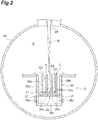
FIG. 2 is a diagram illustrating a molding tank in a pressure vessel and a manufactured object molded in the molding tank. -
FIG. 3 is a diagram for describing a gas supplying step in the additive manufacturing device. - An additive manufacturing device according to one aspect of the present disclosure includes a molding unit including a molding tank accommodating a manufactured object and forming the manufactured object in the molding tank, a pressure vessel accommodating the molding unit, and a gas supply unit connected to the pressure vessel, supplying a gas into the pressure vessel, and configured to pressurize an inner portion of the pressure vessel.
- According to this additive manufacturing device, the molding unit is accommodated in the pressure vessel and the gas is supplied into the pressure vessel by the gas supply unit. For example, the inner portion of the pressure vessel is pressurized after the additive manufacturing of the powder in a vacuum. With the pressure increased, the gas is capable of surrounding the molding tank and flowing into the molding tank, and thus the manufactured object can be rapidly cooled by the gas. As a result, the cooling of the manufactured object can be more effectively promoted than in the case of the related art where radiational cooling is performed with a manufactured object held in a vacuum or the atmosphere or a molding box is cooled by a refrigerant being allowed to flow through a flow path of a molding box.
- In some embodiments, a hole portion allowing an inside and an outside of a wall portion of the molding tank to communicate with each other is provided in the wall portion. In this case, the gas increased in pressure easily flows into the molding tank through the hole portion provided in the wall portion of the molding tank. As a result, the cooling of the manufactured object by the gas is further effectively promoted.
- In some embodiments, the molding tank is configured such that the hole portion remains closed during the molding of the manufactured object and the hole portion opens after the molding of the manufactured object. According to the molding tank configured as described above, the atmosphere in the molding tank (including a vacuum state) is maintained during the molding of the manufactured object and a gas flows into the molding tank after the molding of the manufactured object. As a result, molding and cooling are appropriately performed.
- Another aspect of the present disclosure is a manufacturing method for an additive-manufactured object using a molding unit molding an additive-manufactured object in a molding tank and a pressure vessel accommodating the molding unit. The manufacturing method includes a molding step of molding the additive-manufactured object in the molding tank and a gas supplying step of pressurizing an inner portion of the pressure vessel by supplying a gas into the pressure vessel after the molding step is completed.
- According to this manufacturing method for an additive-manufactured object, the gas supplying step is performed after the molding step is completed, the gas is supplied into the pressure vessel, and the inner portion of the pressure vessel is pressurized. With the pressure increased, the gas is capable of surrounding the molding tank and flowing into the molding tank, and thus the additive-manufactured object can be rapidly cooled by the gas. As a result, the cooling of the additive-manufactured object can be more effectively promoted than in the case of the related art where radiational cooling is performed with a manufactured object held in a vacuum or the atmosphere or a molding box is cooled by a refrigerant being allowed to flow through a flow path of a molding box.
- In some embodiments, a hole portion allowing an inside and an outside of a wall portion of the molding tank to communicate with each other is provided in the wall portion, the hole portion is closed in the molding step, and the hole portion is opened and the gas is introduced into the hole portion in the gas supplying step. When the hole portion is opened/closed at such a timing, the atmosphere in the molding tank (including a vacuum state) is maintained during the molding of the manufactured object and a gas flows into the molding tank after the molding of the manufactured object. As a result, molding and cooling are appropriately performed.
- Hereinafter, an embodiment of the present disclosure will be described with reference to the drawings. It should be noted that the same elements will be denoted by the same reference symbols without redundant description in the description of the drawings.
- A basic configuration of an
additive manufacturing device 1 according to the present embodiment will be described with reference toFIG. 1 . As illustrated inFIG. 1 , theadditive manufacturing device 1 is a device that molds a three-dimensional object by melting and solidifying powder A by irradiating the powder A with an electron beam B. Theadditive manufacturing device 1 includes an electronbeam emission unit 2, amolding unit 3, and acontrol unit 4. - The electron
beam emission unit 2 melts the powder A by emitting the electron beam B to the powder A of themolding unit 3. The electronbeam emission unit 2 may preheat the powder A by irradiating the powder A with the electron beam B before the molding of the object is performed. - The electron
beam emission unit 2 includes anelectron gun unit 21, anaberration coil 22, afocus coil 23, and adeflection coil 24. Theelectron gun unit 21 is electrically connected to thecontrol unit 4, operates in response to a control signal from thecontrol unit 4, and emits the electron beam B. Theelectron gun unit 21 is provided so as to, for example, emit the electron beam B downward. Theaberration coil 22 is electrically connected to thecontrol unit 4 and operates in response to a control signal from thecontrol unit 4. Theaberration coil 22 is installed around the electron beam B emitted from theelectron gun unit 21 and corrects the aberration of the electron beam B. Thefocus coil 23 is electrically connected to thecontrol unit 4 and operates in response to a control signal from thecontrol unit 4. Thefocus coil 23 is installed around the electron beam B emitted from theelectron gun unit 21, converges the electron beam B, and adjusts the focus state at the irradiation position of the electron beam B. Thedeflection coil 24 is electrically connected to thecontrol unit 4 and operates in response to a control signal from thecontrol unit 4. Thedeflection coil 24 is installed around the electron beam B emitted from theelectron gun unit 21 and adjusts the irradiation position of the electron beam B in accordance with a control signal. It should be noted that theaberration coil 22 may be omitted. - The
electron gun unit 21, theaberration coil 22, thefocus coil 23, and thedeflection coil 24 are installed in, for example, atubular column 26. The electronbeam emission unit 2 emits the electron beam B from anemission port 2a provided at the lower end of thecolumn 26 toward a molding surface formed in themolding unit 3. - The
molding unit 3 is a part where a manufactured object C (additive-manufactured object, seeFIG. 2 ), which is a desired object, is molded. Themolding unit 3 includes amolding tank 36, aplate 31, a lifting and loweringdevice 10, twohoppers 34, and anapplication mechanism 33. Themolding unit 3 is provided below the electronbeam emission unit 2. Themolding unit 3 molds the manufactured object C in themolding tank 36. The equipment constituting themolding unit 3 may be unitized. - The
plate 31 is a flat plate-shaped member disposed in themolding tank 36. Theplate 31 supports the object to be molded. Theplate 31 has a circular shape or the like. The shape of theplate 31 corresponds to the shape of a molding region. Theplate 31 has a diameter smaller than the inner diameter of themolding tank 36 and a gap is formed between theplate 31 and aside wall 36a of theside wall 36a. Theplate 31 is disposed on an extension line in the emission direction of the electron beam B and is provided toward, for example, a horizontal direction. Theplate 31 and themolding tank 36 are installed concentrically. - The lifting and lowering
device 10 supports theplate 31 and lifts and lowers theplate 31 in an up-down direction in themolding tank 36. The lifting and loweringdevice 10 has a lifting and loweringstage 35 installed below theplate 31 and supporting theplate 31 and a lifting and loweringmachine 32 lifting and lowering theplate 31 and the lifting and loweringstage 35. The lifting and loweringmachine 32 is electrically connected to thecontrol unit 4 and operates in response to a control signal from thecontrol unit 4. The lifting and loweringmachine 32 moves theplate 31 and the lifting and loweringstage 35 upward in the early stage of the object molding and lowers theplate 31 each time the powder A is melted, solidified, and layered on theplate 31. The manufactured object C is molded on theplate 31. The molding surface is formed on the upper surface of the manufactured object C. Specific configurations of the lifting and loweringdevice 10 and the lifting and loweringmachine 32 are not limited to the above-described configurations and may be other known configurations. The shapes of theplate 31, the lifting and loweringstage 35, and themolding tank 36 can be appropriately changed in accordance with the shape of the manufactured object C or the like. - The
molding tank 36 accommodates the manufactured object C to be molded on theplate 31 and the powder A that has not been melted. Themolding tank 36 is formed in, for example, a cylindrical shape and extends toward the movement direction of theplate 31. Thismolding tank 36 is formed in a circular cross section concentric with theplate 31. As illustrated inFIG. 2 , themolding tank 36 includes the cylindrical side wall (wall portion) 36a and abottom wall 36b closing the lower end of theside wall 36a. The lifting and loweringstage 35 is formed in accordance with the shape of the inner surface of themolding tank 36, that is, theside wall 36a. In a case where the inner surface of themolding tank 36 is circular in a horizontal cross section, the outer shape of the lifting and loweringstage 35 is also circular. As a result, downward leakage of the powder A supplied to themolding tank 36 from the lifting and loweringstage 35 is suppressed. It should be noted that a seal material may be provided in the outer edge portion of the lifting and loweringstage 35 so that downward leakage of the powder A from the lifting and loweringstage 35 is suppressed. The shape of themolding tank 36 is not limited to a cylindrical shape and the shape of themolding tank 36 may be a square tube shape having a rectangular cross section. - The
application mechanism 33 is a member that supplies the powder A onto theplate 31 and levels the surface of the powder A and theapplication mechanism 33 functions as a recoater. For example, a rod-shaped or plate-shaped member is used as theapplication mechanism 33 and theapplication mechanism 33 supplies the powder A to the irradiation region of the electron beam B by moving in the horizontal direction and levels the surface of the powder A. The movement of theapplication mechanism 33 is controlled by an actuator (not illustrated) and a mechanism (not illustrated). Theapplication mechanism 33 operates in response to a control signal from thecontrol unit 4. It should be noted that a known mechanism other than theapplication mechanism 33 may be used as a mechanism leveling the powder A. - The
hopper 34 is a container accommodating the powder A. Adischarge port 34a for discharging the powder A is formed in the lower portion of thehopper 34. The powder A discharged from thedischarge port 34a flows in onto theplate 31 or is supplied onto theplate 31 by theapplication mechanism 33. It should be noted that a mechanism other than theapplication mechanism 33 and thehopper 34 can be used as a mechanism supplying the powder A in layers onto theplate 31. - Multiple powder bodies constitute the powder A. Metallic powder or the like is used as the powder A. In addition, granules larger in particle size than the powder may be used as the powder A insofar as the granules can be melted and solidified by being irradiated with the electron beam B.
- The
control unit 4 is an electronic control unit controlling the entireadditive manufacturing device 1. Thecontrol unit 4 is configured to include a computer and hardware such as a central processing unit (CPU), a read only memory (ROM), and a random access memory (RAM) and software such as a program stored in the ROM constitute the computer. Thecontrol unit 4 executes lifting and lowering control on theplate 31, operation control on theapplication mechanism 33, emission control on the electron beam B, operation control on thedeflection coil 24, and so on. Thecontrol unit 4 outputs a control signal to the lifting and loweringmachine 32, operates the lifting and loweringmachine 32, and adjusts the up-down position of theplate 31 as the lifting and lowering control on theplate 31. Thecontrol unit 4 operates theapplication mechanism 33 before the emission of the electron beam B and causes the powder A to be supplied onto theplate 31 and leveled as the operation control on theapplication mechanism 33. Thecontrol unit 4 outputs a control signal to theelectron gun unit 21 and causes theelectron gun unit 21 to emit the electron beam B as the emission control on the electron beam B. - The
control unit 4 outputs a control signal to thedeflection coil 24 and controls the irradiation position of the electron beam B as the operation control on thedeflection coil 24. For example, three-dimensional computer-aided design (CAD) data on the manufactured object C, which is an object to be molded, is input to thecontrol unit 4. Thecontrol unit 4 generates two-dimensional slice data on the basis of this three-dimensional CAD data. The slice data is, for example, data on a horizontal cross section of the manufactured object C and an aggregate of multiple data corresponding to an up-down position. The region where the powder A on the molding surface is irradiated with the electron beam B is determined on the basis of this slice data and a control signal is output to thedeflection coil 24 in accordance with that region. - In the
additive manufacturing device 1 of the present embodiment, themolding unit 3 is provided in, for example, acylindrical pressure vessel 40. In other words, theadditive manufacturing device 1 accommodates themolding unit 3 including themolding tank 36, theplate 31, the lifting and loweringdevice 10, thehopper 34, and theapplication mechanism 33. In the molding step of molding the manufactured object C in theadditive manufacturing device 1, the inside of thepressure vessel 40 is put into a vacuum or a substantially vacuum state. On the other hand, after the molding of the manufactured object C is completed, that is, after the molding step is completed, an inert gas is supplied into thepressure vessel 40 and an internal space S of thepressure vessel 40 is pressurized. A manufacturing method for the manufactured object C using theadditive manufacturing device 1 includes such a process, and thus the cooling of the manufactured object C is effectively promoted. - Hereinafter, a configuration related to the cooling of the manufactured object C will be described in detail. The
pressure vessel 40 is made of, for example, a steel plate. Thepressure vessel 40 includes, for example, a cylinder portion and end plates joined to both axial ends of the cylinder portion. A clutch ring or the like may be provided in the portion where the cylinder portion and the end plate are joined to each other. Thepressure vessel 40 is installed in a state where the central axis of the cylinder portion is directed in the horizontal direction. In other words, the direction of the central axis of thepressure vessel 40 is substantially orthogonal to the direction of each of the central axes of thecolumn 26 and themolding tank 36. - The
pressure vessel 40 is connected to the lower end of thecolumn 26 of the electronbeam emission unit 2. The inner portions of the electronbeam emission unit 2 and thepressure vessel 40 are airtight with respect to the outside. The lower end of thecolumn 26 may be fitted into a through hole formed in the cylinder portion of thepressure vessel 40 and then joined to the cylinder portion by welding or the like. Alternatively, the lower end of thecolumn 26 may be joined by means of a fastening member or the like to a nozzle (piping, a flange, or the like) attached to the cylinder portion of thepressure vessel 40. The form of connection of thepressure vessel 40 to thecolumn 26 is not limited to the above and may be another form in which airtightness can be maintained. Thepressure vessel 40 may be installed in, for example, a state where the central axis of the cylinder portion is directed vertically (vertical installation) instead of horizontally (horizontal installation). In other words, the direction of the central axis of thepressure vessel 40 and the direction of each of the central axes of thecolumn 26 and themolding tank 36 may be in the same direction. - The
pressure vessel 40 has a structure capable of withstanding a pressure of, for example, approximately 1 MPa. Thepressure vessel 40 may be configured to, for example, comply with theClass 2 pressure vessel standards. The shape of thepressure vessel 40 is not limited to a cylindrical shape and the shape may be a square tube shape having a rectangular cross section. - The
molding tank 36, the lifting and loweringdevice 10, thehopper 34, and theapplication mechanism 33 of themolding unit 3 are fixed to the inner surface side of thepressure vessel 40 directly or via a support member or the like. In a case where the equipment of themolding unit 3 is unitized, the unit may be fixed to the inner surface side of thepressure vessel 40. A plurality of leg portions for installing thepressure vessel 40 and the electronbeam emission unit 2 in a self-standing state are attached in the lower portion of the outer peripheral surface of thepressure vessel 40. - The
additive manufacturing device 1 further includes agas supply unit 41 connected to thepressure vessel 40 and supplying an inert gas into thepressure vessel 40. The inert gas used in theadditive manufacturing device 1 is, for example, nitrogen. Thegas supply unit 41 is disposed outside thepressure vessel 40. Thegas supply unit 41 is connected to thepressure vessel 40 by, for example, agas line 42. Thegas line 42, which is piping, communicates with the internal space S of thepressure vessel 40 and introduces the inert gas that is sent from thegas supply unit 41 into the internal space S of thepressure vessel 40. Thegas line 42 may be provided with valves or the like that enable or disable gas supply to thepressure vessel 40. - The
gas supply unit 41 includes, for example, an inert gas storage tank (not illustrated) and air supply means (not illustrated) such as a pump and a blower for sending the inert gas that is stored in the storage tank to thepressure vessel 40. In other words, in the present embodiment, the inert gas has a gas source disposed outside thepressure vessel 40. The air supply means of thegas supply unit 41 operates in response to, for example, a control signal from thecontrol unit 4. Thepressure vessel 40 may be provided with a pressure gauge (not illustrated) detecting the pressure of the internal space S. Thecontrol unit 4 may control the air supply means of thegas supply unit 41 on the basis of a signal indicating the pressure of the internal space S output from the pressure gauge. - The
gas supply unit 41 supplies an inert gas into thepressure vessel 40 under the control of thecontrol unit 4 such that the pressure of the internal space S of thepressure vessel 40 becomes, for example, a value in the range of 0.1 to 1 MPa. In this manner, thegas supply unit 41 is configured to pressurize the inner portion of thepressure vessel 40 to the atmospheric pressure or a higher-than-atmospheric pressure. The degree of pressurization by thegas supply unit 41 can be appropriately set in accordance with the size of themolding tank 36, the size of the manufactured object C, the material of the powder A, the required cooling time, or the like. It should be noted that the gas in thepressure vessel 40 is not discharged to the outside when the inner portion of thepressure vessel 40 is pressurized by the inert gas being supplied. - A
fan 46 and a radiator (heat exchanger) 47 may be attached to the cylinder portion of thepressure vessel 40. Thefan 46 and theradiator 47 can be controlled by thecontrol unit 4. An electric current is supplied from an external electric power source, the blade portions of thefan 46 rotate, and the inert gas of the internal space S of thepressure vessel 40 is passed with respect to theradiator 47 through which cooling water or the like flows. As a result, the inert gas in thepressure vessel 40 is cooled and the cooling of the manufactured object C is further promoted. Aduct 48 for promoting inert gas convection may be provided on the inner surface side of thepressure vessel 40. The cooling of the manufactured object C can be accelerated by means of thefan 46, theradiator 47, and theduct 48. Thefan 46 and theradiator 47 may be installed outside thepressure vessel 40. Thefan 46 and theradiator 47 may be connected to the internal space S of thepressure vessel 40 via a pipe (flow path, not illustrated). - The configuration of the
molding tank 36 and its surroundings will be described in detail with reference toFIG. 2 . Theside wall 36a of thecylindrical molding tank 36 is provided with a plurality ofhole portions 36c allowing the inside and the outside of theside wall 36a to communicate with each other. The plurality ofhole portions 36c may be formed in the lower portion theside wall 36a. The plurality ofhole portions 36c may be formed at equal intervals in a circumferential direction. It should be noted that only onehole portion 36c may be formed. - A plurality of opening/
closing portions 37 respectively covering and closing thehole portions 36c are attached to theside wall 36a of themolding tank 36. The opening/closing portions 37 are controlled by, for example, thecontrol unit 4 and are capable of opening and closing therespective hole portions 36c. The structure of the opening/closing mechanism of thehole portion 36c is not particularly limited. For example, eachhole portion 36c may be opened/closed by the plurality of opening/closing portions 37 being attached to a drive ring disposed on the outer peripheral side of themolding tank 36 and the drive ring being moved along the circumferential direction by an actuator. - The lifting and lowering
stage 35 is provided with a plurality ofventilation holes 35a penetrating the lifting and loweringstage 35 in the plate thickness direction (up-down direction). The plurality ofventilation holes 35a may be uniformly formed in the entire region that is positioned below theplate 31. It should be noted that only oneventilation hole 35a may be formed. - Further, the
plate 31 is provided with one ormore ventilation holes 31a penetrating theplate 31 in the plate thickness direction (up-down direction). Theventilation hole 31a may be formed so as to correspond to the shape of the bottom portion of the manufactured object C. In other words, theventilation hole 31a may be formed at a position corresponding to a gap Ca of the manufactured object C. It should be noted that the manufactured object C that has a plurality of columnar structures is illustrated and the gap Ca is formed between the columns in the example ofFIG. 2 . Further, theventilation hole 31a is formed at the position of the lower end of the gap Ca. - These
hole portion 36c,ventilation hole 35a, andventilation hole 31a promote the cooling of the inner portion of themolding tank 36 by allowing the inert gas supplied from thegas supply unit 41 to be introduced into themolding tank 36 after the molding of the manufactured object C is completed. It should be noted that theventilation hole 35a and theventilation hole 31a may be omitted. In addition, one or more hole portions may be provided in thebottom wall 36b of themolding tank 36. In that case, an opening/closing mechanism opening/closing the hole portion provided in thebottom wall 36b may be provided. - As described above, the space in the
column 26 and the internal space S of thepressure vessel 40 are connected to each other. The internal space of thepressure vessel 40 communicates with the internal space of thecolumn 26. During the molding step, the electron beam B passes through these communicating spaces (seeFIG. 2 ). As illustrated inFIG. 1 , a sealingvalve 43 is attached via an O-ring 44 to the lower end of the electronbeam emission unit 2, that is, the lower end of thecolumn 26. The sealingvalve 43 is controlled by, for example, thecontrol unit 4 and is capable of opening/closing theemission port 2a. In a state where the sealingvalve 43 is closed, the sealingvalve 43 shields the space in thecolumn 26 from the internal space S of thepressure vessel 40. Specifically, the sealingvalve 43 seals theemission port 2a after the completion of the molding step and before thegas supply unit 41 supplies the inert gas to thepressure vessel 40. As a result, inert gas intrusion into the electronbeam emission unit 2 is prevented and the electronbeam emission unit 2 is protected. It should be noted that the sealingvalve 43 and the O-ring 44 are not illustrated inFIG. 2 . - Subsequently, a manufacturing method for the manufactured object C of the present embodiment will be described with reference to
FIGS. 2 and3 . First, a molding step of molding the manufactured object C is performed. As illustrated inFIG. 2 , in the molding step, the inside of thepressure vessel 40 is put into a vacuum or a substantially vacuum state and theemission port 2a is opened. Thehole portion 36c of themolding tank 36 remains closed by the opening/closingportion 37. Meanwhile, the powder A is discharged through thedischarge port 34a of thehopper 34 and the powder A is supplied onto theplate 31 by theapplication mechanism 33. The electronbeam emission unit 2 is controlled by thecontrol unit 4 and the powder A on the molding surface is irradiated with the electron beam B. For example, in the molding step, one or more preheating processes and a main melting process are performed for each layer. A predetermined region is irradiated with the electron beam B in each of the plurality of layers and the powder A is melt and solidified into a desired shape. The manufactured object C is molded as a result of the molding step. The gap Ca of the manufactured object C and agap 36d between the manufactured object C and thebottom wall 36b remain filled with the powder A. - Next, the emission of the electron beam B is stopped and the sealing
valve 43 is closed as illustrated inFIG. 3 . A gas supplying step of supplying a gas into thepressure vessel 40 is performed after the completion of the molding step. In the gas supplying step, an inert gas is supplied from thegas supply unit 41 to the internal space S of thepressure vessel 40 and the inner portion of thepressure vessel 40 is pressurized until the inside of thepressure vessel 40 reaches a predetermined value in the range of, for example, 0.1 to 1 MPa. At the point in time when the molding step is completed, the lifting and loweringstage 35 is positioned below thehole portion 36c. The opening/closingportion 37 is driven in the opening direction and thehole portion 36c opens to the outside. As a result, the inert gas is introduced into thehole portion 36c, passes through the gap Ca through theventilation hole 31a, and passes through thegap 36d through the space between theplate 31 and theside wall 36a (see the arrow in the drawing). The inert gas cools the powder A present in the gap Ca and thegap 36d and cools the manufactured object C. In addition, the inert gas surrounds themolding tank 36 and cools themolding tank 36 from the outer peripheral side. On the other hand, when the inert gas is supplied to thepressure vessel 40, thefan 46 and theradiator 47 are operated and the convection of the inert gas is promoted. The manufactured object C is taken out when the temperature of the manufactured object C reaches a predetermined value or less and the cooling is completed. It should be noted thatFIG. 3 schematically illustrates how the opening/closingportion 37 opens. - It should be noted that the
plate 31 may be positioned above thehole portion 36c at the point in time when the molding step is completed. In this case, the gas introduced into themolding tank 36 through thehole portion 36c is supplied onto theplate 31 through theventilation hole 31 a from below theplate 31. - In addition, the lifting and lowering
stage 35 may be positioned above thehole portion 36c although the lifting and loweringstage 35 is positioned below thehole portion 36c at the point in time when the molding step is completed in the above-described form. In other words, theventilation hole 35a and theventilation hole 31a may be positioned above thehole portion 36c at the point in time when the molding step is completed. In this case, the gas introduced into themolding tank 36 through thehole portion 36c is capable of flowing in onto theplate 31 through theventilation hole 35a and theventilation hole 31a from below the lifting and loweringstage 35. - In a case where a hole portion is provided in the
bottom wall 36b of themolding tank 36, the gas introduced into themolding tank 36 through the hole portion of thebottom wall 36b is capable of flowing in onto theplate 31 through theventilation hole 35a and theventilation hole 31a from below the lifting and loweringstage 35. - According to the
additive manufacturing device 1 and the manufacturing method for the manufactured object C of the present embodiment, the gas supplying step is performed after the molding step is completed, the inert gas is supplied into thepressure vessel 40, and the inner portion of thepressure vessel 40 is pressurized. For example, the inner portion of thepressure vessel 40 is pressurized after the additive manufacturing of the powder in a vacuum. With the pressure increased, the inert gas is capable of surrounding themolding tank 36 of themolding unit 3 and flowing into themolding tank 36, and thus the manufactured object C can be rapidly cooled by the inert gas. As a result, the cooling of the manufactured object C can be more effectively promoted than in the case of the related art where radiational cooling is performed with a manufactured object held in a vacuum or the atmosphere or a molding box is cooled by a refrigerant being allowed to flow through a flow path of a molding box. According to the present embodiment, the manufactured object C is rapidly cooled. The cooling time of the manufactured object C according to the present embodiment is significantly shorter than (is, for example, approximately 10% of) the cooling time in a vacuum or the atmosphere of the related art. - The inert gas increased in pressure easily flows into the
molding tank 36 through thehole portion 36c provided in theside wall 36a of themolding tank 36. As a result, the cooling of the manufactured object C by the inert gas is further effectively promoted. - The
hole portion 36c remains closed during the molding of the manufactured object C and is opened after the manufactured object C is molded. In other words, thehole portion 36c is closed in the molding step and thehole portion 36c is opened and an inert gas is introduced into thehole portion 36c in the gas supplying step. When thehole portion 36c is opened/closed at such a timing in themolding tank 36, the atmosphere in the molding tank 36 (including a vacuum state) is maintained during the molding of the manufactured object C and an inert gas flows into themolding tank 36 after the molding of the manufactured object C. As a result, molding and cooling are appropriately performed. - The present invention is not limited to the embodiment of the present disclosure that has been described above. For example, the type of the gas that is used for the cooling may be an inert gas other than nitrogen. For example, the powder material is not limited to metal and the powder material may be resin, ceramic, or the like. In addition, argon, helium, or the like may be used as a cooling gas. In addition, another type of gas may be used insofar as the gas does not adversely affect the manufactured object C. For example, another type of gas may be used insofar as the gas does not cause a reaction even in touching the manufactured object C. For example, an oxygen-containing gas (such as air) may be used with respect to the manufactured object C made of ceramic.
- A hole portion may be provided at a part other than the lower portion of the
side wall 36a of themolding tank 36. The hole portion may be configured to be opened during molding. The hole portion may be provided in the upper portion of theside wall 36a and the opening/closingportion 37 covering thehole portion 36c may be omitted. No hole portion may be provided with respect to themolding tank 36. - In addition, in the manufacturing method for an additive-manufactured object, cooling can also be performed by means of a device different from the
additive manufacturing device 1. In other words, thepressure vessel 40 may be removed from theadditive manufacturing device 1 and the cooling of themolding unit 3 and the manufactured object C by gas supply and pressurization may be performed in another place without the cooling and the preceding processes being performed in theadditive manufacturing device 1. In this case, thepressure vessel 40 may be configured to be removable from theadditive manufacturing device 1 in a state where themolding unit 3 is incorporated. Thegas supply unit 41 and thegas line 42 may be omitted in theadditive manufacturing device 1. In addition, the vessel accommodating themolding unit 3 may be another vessel that is capable of withstanding vacuumization and is not a pressure vessel, themolding unit 3 may be moved under a certain vacuum environment after being taken out of the vessel after molding, and the manufactured object C may be cooled in a pressure vessel provided in a place different from a molding area. The manufactured object C after the molding may be moved in the atmosphere in a case where the manufactured object C is made of a material (non-metal material) that does not react with oxygen or the like even when exposed to the atmosphere. In that case, a gas supply unit is connected to the pressure vessel. - The pressure in the case of pressurization of the inner portion of the pressure vessel can be appropriately changed. The pressure vessel may not be configured to comply with standards. Pressure setting based on no established standards may be performed with respect to the pressure vessel.
- The additive manufacturing device is not limited to a molding device to which an electron beam melting method is applied and the additive manufacturing device may be, for example, a molding device to which a laser melting method is applied. In other words, the beam that is emitted to the powder A in the additive manufacturing device may be a laser beam. The beam that is emitted to the powder A in the additive manufacturing device may be a charged particle beam, which is a concept including an electron beam and an ion beam. The beam that is emitted to the powder A in the additive manufacturing device may be an energy beam capable of supplying energy to the powder A.
- According to several aspects of the present disclosure, cooling of a manufactured object can be effectively promoted.
- 1: additive manufacturing device, 2: electron beam emission unit, 3: molding unit, 4: control unit, 31: plate, 33: application mechanism, 34: hopper, 35: lifting and lowering stage, 36: molding tank, 36a: side wall (wall portion), 36c: hole portion, 37: opening/closing portion, 40: pressure vessel, 41: gas supply unit, 42: gas line, A: powder, C: manufactured object (additive-manufactured object), Ca: gap, S: internal space.
Claims (5)
- An additive manufacturing device comprising:a molding unit including a molding tank accommodating a manufactured object and forming the manufactured object in the molding tank;a pressure vessel accommodating the molding unit; anda gas supply unit connected to the pressure vessel, supplying a gas into the pressure vessel, and configured to pressurize an inner portion of the pressure vessel.
- The additive manufacturing device according to claim 1, wherein a hole portion allowing an inside and an outside of a wall portion of the molding tank to communicate with each other is provided in the wall portion.
- The additive manufacturing device according to claim 2, wherein the molding tank is configured such that the hole portion remains closed during the molding of the manufactured object and the hole portion opens after the molding of the manufactured object.
- A manufacturing method for an additive-manufactured object using a molding unit molding the additive-manufactured object in a molding tank and a pressure vessel accommodating the molding unit, the manufacturing method comprising:a molding step of molding the additive-manufactured object in the molding tank; anda gas supplying step of pressurizing an inner portion of the pressure vessel by supplying a gas into the pressure vessel after the molding step is completed.
- The manufacturing method for an additive-manufactured object according to claim 4, wherein
a hole portion allowing an inside and an outside of a wall portion of the molding tank to communicate with each other is provided in the wall portion,
the hole portion is closed in the molding step, and
the hole portion is opened and the gas is introduced into the hole portion in the gas supplying step.
Applications Claiming Priority (2)
| Application Number | Priority Date | Filing Date | Title |
|---|---|---|---|
| JP2017211075 | 2017-10-31 | ||
| PCT/JP2018/040173 WO2019088043A1 (en) | 2017-10-31 | 2018-10-29 | 3d layering/molding device and manufacturing method for 3d layered/molded object |
Publications (3)
| Publication Number | Publication Date |
|---|---|
| EP3705268A1 true EP3705268A1 (en) | 2020-09-09 |
| EP3705268A4 EP3705268A4 (en) | 2020-12-16 |
| EP3705268B1 EP3705268B1 (en) | 2023-04-05 |
Family
ID=66333519
Family Applications (1)
| Application Number | Title | Priority Date | Filing Date |
|---|---|---|---|
| EP18874726.5A Active EP3705268B1 (en) | 2017-10-31 | 2018-10-29 | 3d layering/molding device and manufacturing method for 3d layered/molded object |
Country Status (5)
| Country | Link |
|---|---|
| US (1) | US11383443B2 (en) |
| EP (1) | EP3705268B1 (en) |
| JP (1) | JP6881595B2 (en) |
| CN (1) | CN111278629B (en) |
| WO (1) | WO2019088043A1 (en) |
Families Citing this family (1)
| Publication number | Priority date | Publication date | Assignee | Title |
|---|---|---|---|---|
| DE102017104351A1 (en) * | 2017-03-02 | 2018-09-06 | Cl Schutzrechtsverwaltungs Gmbh | Device for the additive production of three-dimensional objects |
Family Cites Families (26)
| Publication number | Priority date | Publication date | Assignee | Title |
|---|---|---|---|---|
| US4818562A (en) | 1987-03-04 | 1989-04-04 | Westinghouse Electric Corp. | Casting shapes |
| EP0289116A1 (en) | 1987-03-04 | 1988-11-02 | Westinghouse Electric Corporation | Method and device for casting powdered materials |
| AU9065991A (en) | 1990-11-09 | 1992-06-11 | Dtm Corporation | Controlled gas flow for selective laser sintering |
| DE10105504A1 (en) | 2001-02-07 | 2002-08-14 | Eos Electro Optical Syst | Powder treatment device for a device for producing a three-dimensional object, device for producing a three-dimensional object and method for producing a three-dimensional object |
| DE10342883B4 (en) | 2003-09-15 | 2007-07-19 | Trumpf Werkzeugmaschinen Gmbh + Co. Kg | Method and device for producing a three-dimensional molded body |
| DE10342882A1 (en) | 2003-09-15 | 2005-05-19 | Trumpf Werkzeugmaschinen Gmbh + Co. Kg | Apparatus and method for producing a three-dimensional shaped body |
| US7521652B2 (en) | 2004-12-07 | 2009-04-21 | 3D Systems, Inc. | Controlled cooling methods and apparatus for laser sintering part-cake |
| JP3980610B2 (en) | 2005-07-26 | 2007-09-26 | 株式会社アスペクト | Powder sintering additive manufacturing equipment |
| DE102006053121B3 (en) | 2006-11-10 | 2007-12-27 | Eos Gmbh Electro Optical Systems | Coating device for applying powdered layers to a device for producing a three-dimensional object comprises longitudinal walls joined together, a unit for fluidizing powdered material and a controlling and/or regulating unit |
| KR101491678B1 (en) | 2007-05-15 | 2015-02-09 | 아르켐 에이비 | Method and apparatus for manufacturing a three-dimensional object |
| US8373092B2 (en) * | 2008-04-09 | 2013-02-12 | The Boeing Company | Purge and sealant cap for selective laser sintering build frame |
| JP5301217B2 (en) * | 2008-08-22 | 2013-09-25 | パナソニック株式会社 | Manufacturing method and manufacturing apparatus for three-dimensional shaped object |
| JP5250338B2 (en) | 2008-08-22 | 2013-07-31 | パナソニック株式会社 | Manufacturing method of three-dimensional shaped object, manufacturing apparatus thereof, and three-dimensional shaped object |
| DE102011085154A1 (en) | 2011-10-25 | 2013-04-25 | Evonik Industries Ag | Device for preventing deposits on optical components in laser sintering |
| RU2580145C2 (en) * | 2013-11-21 | 2016-04-10 | Юрий Александрович Чивель | Production of 3d articles with gradient of properties of powders and device to this end |
| JP6338422B2 (en) | 2014-03-31 | 2018-06-06 | 三菱重工業株式会社 | 3D laminating equipment |
| JP2015193187A (en) | 2014-03-31 | 2015-11-05 | 日本電子株式会社 | Three-dimensional laminate molding apparatus and three-dimensional laminate molding method |
| JP5841649B1 (en) * | 2014-10-08 | 2016-01-13 | 株式会社ソディック | Additive manufacturing equipment |
| CN104493165A (en) * | 2014-12-30 | 2015-04-08 | 深圳市圆梦精密技术研究院 | Electron beam melting and laser milling composite 3D printing equipment |
| US9981312B2 (en) * | 2015-05-11 | 2018-05-29 | Wisconsin Alumni Research Foundation | Three-dimension printer with mechanically scanned cathode-comb |
| JP6545586B2 (en) | 2015-09-14 | 2019-07-17 | 株式会社東芝 | Additive manufacturing equipment |
| US20180169938A1 (en) | 2015-11-13 | 2018-06-21 | Technology Research Association For Future Additive Manufacturing | Three-dimensional laminating and shaping apparatus, method of manufacturing three-dimensional laminating and shaping apparatus, and program for manufacturing three-dimensional laminating and shaping apparatus |
| US20170165911A1 (en) | 2015-12-15 | 2017-06-15 | Nabtesco Corporation | Three dimensional modeling apparatus |
| JP2017109355A (en) | 2015-12-15 | 2017-06-22 | ナブテスコ株式会社 | 3D modeling equipment |
| JP6701783B2 (en) | 2016-02-16 | 2020-05-27 | 日本ポリプロ株式会社 | Multilayer foamed sheet having a non-foamed layer containing a long-chain branched polypropylene resin composition |
| JP6653590B2 (en) | 2016-02-16 | 2020-02-26 | 株式会社アスペクト | Cooling optimization device and cooling optimization method |
-
2018
- 2018-10-29 EP EP18874726.5A patent/EP3705268B1/en active Active
- 2018-10-29 JP JP2019550381A patent/JP6881595B2/en active Active
- 2018-10-29 US US16/759,516 patent/US11383443B2/en active Active
- 2018-10-29 WO PCT/JP2018/040173 patent/WO2019088043A1/en not_active Ceased
- 2018-10-29 CN CN201880069820.2A patent/CN111278629B/en active Active
Also Published As
| Publication number | Publication date |
|---|---|
| JP6881595B2 (en) | 2021-06-02 |
| JPWO2019088043A1 (en) | 2020-07-27 |
| EP3705268A4 (en) | 2020-12-16 |
| US20200276762A1 (en) | 2020-09-03 |
| CN111278629A (en) | 2020-06-12 |
| EP3705268B1 (en) | 2023-04-05 |
| CN111278629B (en) | 2022-06-07 |
| WO2019088043A1 (en) | 2019-05-09 |
| US11383443B2 (en) | 2022-07-12 |
Similar Documents
| Publication | Publication Date | Title |
|---|---|---|
| KR102316508B1 (en) | Multi-chamber deposition equipment for arbitrary shape fabrication | |
| US20200331198A1 (en) | Additive manufacturing device and additive manufacturing method | |
| US11110518B2 (en) | Method and apparatus for manufacturing a three-dimensional object | |
| JP2019081937A (en) | Powder saving device and powder saving method | |
| EP3705213A1 (en) | Three-dimensional shaping device and three-dimensional shaping method | |
| WO2019088091A1 (en) | Three-dimensional shaping device and three-dimensional shaping method | |
| US20150314389A1 (en) | Machine and Method for Additive Manufacturing | |
| EP3705268B1 (en) | 3d layering/molding device and manufacturing method for 3d layered/molded object | |
| US11618074B2 (en) | Method of manufacturing metal member | |
| US11554442B2 (en) | Additive manufacturing device and additive manufacturing method | |
| WO2019220901A1 (en) | Three-dimensional shaping device and three-dimensional shaping method | |
| JP6870579B2 (en) | Three-dimensional laminated modeling equipment | |
| EP3427867B1 (en) | Device for manufacturing three-dimensional shaped object | |
| KR20180006822A (en) | 3D printer chamber structure with separated laser |
Legal Events
| Date | Code | Title | Description |
|---|---|---|---|
| STAA | Information on the status of an ep patent application or granted ep patent |
Free format text: STATUS: THE INTERNATIONAL PUBLICATION HAS BEEN MADE |
|
| PUAI | Public reference made under article 153(3) epc to a published international application that has entered the european phase |
Free format text: ORIGINAL CODE: 0009012 |
|
| STAA | Information on the status of an ep patent application or granted ep patent |
Free format text: STATUS: REQUEST FOR EXAMINATION WAS MADE |
|
| 17P | Request for examination filed |
Effective date: 20200507 |
|
| AK | Designated contracting states |
Kind code of ref document: A1 Designated state(s): AL AT BE BG CH CY CZ DE DK EE ES FI FR GB GR HR HU IE IS IT LI LT LU LV MC MK MT NL NO PL PT RO RS SE SI SK SM TR |
|
| AX | Request for extension of the european patent |
Extension state: BA ME |
|
| A4 | Supplementary search report drawn up and despatched |
Effective date: 20201112 |
|
| RIC1 | Information provided on ipc code assigned before grant |
Ipc: B33Y 30/00 20150101ALI20201106BHEP Ipc: B29C 64/371 20170101AFI20201106BHEP Ipc: B22F 3/16 20060101ALI20201106BHEP Ipc: B33Y 40/20 20200101ALI20201106BHEP Ipc: B29C 64/25 20170101ALI20201106BHEP Ipc: B22F 3/105 20060101ALI20201106BHEP Ipc: B22F 3/24 20060101ALN20201106BHEP Ipc: B33Y 10/00 20150101ALI20201106BHEP |
|
| DAV | Request for validation of the european patent (deleted) | ||
| DAX | Request for extension of the european patent (deleted) | ||
| GRAP | Despatch of communication of intention to grant a patent |
Free format text: ORIGINAL CODE: EPIDOSNIGR1 |
|
| STAA | Information on the status of an ep patent application or granted ep patent |
Free format text: STATUS: GRANT OF PATENT IS INTENDED |
|
| RIC1 | Information provided on ipc code assigned before grant |
Ipc: B22F 3/24 20060101ALN20220926BHEP Ipc: B29C 64/364 20170101ALI20220926BHEP Ipc: B29C 64/268 20170101ALI20220926BHEP Ipc: B22F 12/70 20210101ALI20220926BHEP Ipc: B33Y 40/20 20200101ALI20220926BHEP Ipc: B33Y 30/00 20150101ALI20220926BHEP Ipc: B33Y 10/00 20150101ALI20220926BHEP Ipc: B29C 64/25 20170101ALI20220926BHEP Ipc: B22F 3/16 20060101ALI20220926BHEP Ipc: B22F 3/105 20060101ALI20220926BHEP Ipc: B29C 64/371 20170101AFI20220926BHEP |
|
| INTG | Intention to grant announced |
Effective date: 20221027 |
|
| GRAS | Grant fee paid |
Free format text: ORIGINAL CODE: EPIDOSNIGR3 |
|
| GRAA | (expected) grant |
Free format text: ORIGINAL CODE: 0009210 |
|
| STAA | Information on the status of an ep patent application or granted ep patent |
Free format text: STATUS: THE PATENT HAS BEEN GRANTED |
|
| AK | Designated contracting states |
Kind code of ref document: B1 Designated state(s): AL AT BE BG CH CY CZ DE DK EE ES FI FR GB GR HR HU IE IS IT LI LT LU LV MC MK MT NL NO PL PT RO RS SE SI SK SM TR |
|
| REG | Reference to a national code |
Ref country code: GB Ref legal event code: FG4D |
|
| REG | Reference to a national code |
Ref country code: CH Ref legal event code: EP |
|
| REG | Reference to a national code |
Ref country code: AT Ref legal event code: REF Ref document number: 1557913 Country of ref document: AT Kind code of ref document: T Effective date: 20230415 |
|
| REG | Reference to a national code |
Ref country code: SE Ref legal event code: TRGR |
|
| REG | Reference to a national code |
Ref country code: DE Ref legal event code: R096 Ref document number: 602018048193 Country of ref document: DE |
|
| REG | Reference to a national code |
Ref country code: IE Ref legal event code: FG4D |
|
| REG | Reference to a national code |
Ref country code: LT Ref legal event code: MG9D |
|
| REG | Reference to a national code |
Ref country code: NL Ref legal event code: MP Effective date: 20230405 |
|
| REG | Reference to a national code |
Ref country code: AT Ref legal event code: MK05 Ref document number: 1557913 Country of ref document: AT Kind code of ref document: T Effective date: 20230405 |
|
| PG25 | Lapsed in a contracting state [announced via postgrant information from national office to epo] |
Ref country code: NL Free format text: LAPSE BECAUSE OF FAILURE TO SUBMIT A TRANSLATION OF THE DESCRIPTION OR TO PAY THE FEE WITHIN THE PRESCRIBED TIME-LIMIT Effective date: 20230405 |
|
| PG25 | Lapsed in a contracting state [announced via postgrant information from national office to epo] |
Ref country code: PT Free format text: LAPSE BECAUSE OF FAILURE TO SUBMIT A TRANSLATION OF THE DESCRIPTION OR TO PAY THE FEE WITHIN THE PRESCRIBED TIME-LIMIT Effective date: 20230807 Ref country code: NO Free format text: LAPSE BECAUSE OF FAILURE TO SUBMIT A TRANSLATION OF THE DESCRIPTION OR TO PAY THE FEE WITHIN THE PRESCRIBED TIME-LIMIT Effective date: 20230705 Ref country code: ES Free format text: LAPSE BECAUSE OF FAILURE TO SUBMIT A TRANSLATION OF THE DESCRIPTION OR TO PAY THE FEE WITHIN THE PRESCRIBED TIME-LIMIT Effective date: 20230405 Ref country code: AT Free format text: LAPSE BECAUSE OF FAILURE TO SUBMIT A TRANSLATION OF THE DESCRIPTION OR TO PAY THE FEE WITHIN THE PRESCRIBED TIME-LIMIT Effective date: 20230405 |
|
| PG25 | Lapsed in a contracting state [announced via postgrant information from national office to epo] |
Ref country code: RS Free format text: LAPSE BECAUSE OF FAILURE TO SUBMIT A TRANSLATION OF THE DESCRIPTION OR TO PAY THE FEE WITHIN THE PRESCRIBED TIME-LIMIT Effective date: 20230405 Ref country code: PL Free format text: LAPSE BECAUSE OF FAILURE TO SUBMIT A TRANSLATION OF THE DESCRIPTION OR TO PAY THE FEE WITHIN THE PRESCRIBED TIME-LIMIT Effective date: 20230405 Ref country code: LV Free format text: LAPSE BECAUSE OF FAILURE TO SUBMIT A TRANSLATION OF THE DESCRIPTION OR TO PAY THE FEE WITHIN THE PRESCRIBED TIME-LIMIT Effective date: 20230405 Ref country code: LT Free format text: LAPSE BECAUSE OF FAILURE TO SUBMIT A TRANSLATION OF THE DESCRIPTION OR TO PAY THE FEE WITHIN THE PRESCRIBED TIME-LIMIT Effective date: 20230405 Ref country code: IS Free format text: LAPSE BECAUSE OF FAILURE TO SUBMIT A TRANSLATION OF THE DESCRIPTION OR TO PAY THE FEE WITHIN THE PRESCRIBED TIME-LIMIT Effective date: 20230805 Ref country code: HR Free format text: LAPSE BECAUSE OF FAILURE TO SUBMIT A TRANSLATION OF THE DESCRIPTION OR TO PAY THE FEE WITHIN THE PRESCRIBED TIME-LIMIT Effective date: 20230405 Ref country code: GR Free format text: LAPSE BECAUSE OF FAILURE TO SUBMIT A TRANSLATION OF THE DESCRIPTION OR TO PAY THE FEE WITHIN THE PRESCRIBED TIME-LIMIT Effective date: 20230706 Ref country code: AL Free format text: LAPSE BECAUSE OF FAILURE TO SUBMIT A TRANSLATION OF THE DESCRIPTION OR TO PAY THE FEE WITHIN THE PRESCRIBED TIME-LIMIT Effective date: 20230405 |
|
| PG25 | Lapsed in a contracting state [announced via postgrant information from national office to epo] |
Ref country code: FI Free format text: LAPSE BECAUSE OF FAILURE TO SUBMIT A TRANSLATION OF THE DESCRIPTION OR TO PAY THE FEE WITHIN THE PRESCRIBED TIME-LIMIT Effective date: 20230405 |
|
| REG | Reference to a national code |
Ref country code: DE Ref legal event code: R097 Ref document number: 602018048193 Country of ref document: DE |
|
| PG25 | Lapsed in a contracting state [announced via postgrant information from national office to epo] |
Ref country code: SK Free format text: LAPSE BECAUSE OF FAILURE TO SUBMIT A TRANSLATION OF THE DESCRIPTION OR TO PAY THE FEE WITHIN THE PRESCRIBED TIME-LIMIT Effective date: 20230405 |
|
| PG25 | Lapsed in a contracting state [announced via postgrant information from national office to epo] |
Ref country code: SM Free format text: LAPSE BECAUSE OF FAILURE TO SUBMIT A TRANSLATION OF THE DESCRIPTION OR TO PAY THE FEE WITHIN THE PRESCRIBED TIME-LIMIT Effective date: 20230405 Ref country code: SK Free format text: LAPSE BECAUSE OF FAILURE TO SUBMIT A TRANSLATION OF THE DESCRIPTION OR TO PAY THE FEE WITHIN THE PRESCRIBED TIME-LIMIT Effective date: 20230405 Ref country code: RO Free format text: LAPSE BECAUSE OF FAILURE TO SUBMIT A TRANSLATION OF THE DESCRIPTION OR TO PAY THE FEE WITHIN THE PRESCRIBED TIME-LIMIT Effective date: 20230405 Ref country code: EE Free format text: LAPSE BECAUSE OF FAILURE TO SUBMIT A TRANSLATION OF THE DESCRIPTION OR TO PAY THE FEE WITHIN THE PRESCRIBED TIME-LIMIT Effective date: 20230405 Ref country code: DK Free format text: LAPSE BECAUSE OF FAILURE TO SUBMIT A TRANSLATION OF THE DESCRIPTION OR TO PAY THE FEE WITHIN THE PRESCRIBED TIME-LIMIT Effective date: 20230405 Ref country code: CZ Free format text: LAPSE BECAUSE OF FAILURE TO SUBMIT A TRANSLATION OF THE DESCRIPTION OR TO PAY THE FEE WITHIN THE PRESCRIBED TIME-LIMIT Effective date: 20230405 |
|
| PLBE | No opposition filed within time limit |
Free format text: ORIGINAL CODE: 0009261 |
|
| STAA | Information on the status of an ep patent application or granted ep patent |
Free format text: STATUS: NO OPPOSITION FILED WITHIN TIME LIMIT |
|
| 26N | No opposition filed |
Effective date: 20240108 |
|
| PG25 | Lapsed in a contracting state [announced via postgrant information from national office to epo] |
Ref country code: SI Free format text: LAPSE BECAUSE OF FAILURE TO SUBMIT A TRANSLATION OF THE DESCRIPTION OR TO PAY THE FEE WITHIN THE PRESCRIBED TIME-LIMIT Effective date: 20230405 |
|
| PG25 | Lapsed in a contracting state [announced via postgrant information from national office to epo] |
Ref country code: SI Free format text: LAPSE BECAUSE OF FAILURE TO SUBMIT A TRANSLATION OF THE DESCRIPTION OR TO PAY THE FEE WITHIN THE PRESCRIBED TIME-LIMIT Effective date: 20230405 Ref country code: IT Free format text: LAPSE BECAUSE OF FAILURE TO SUBMIT A TRANSLATION OF THE DESCRIPTION OR TO PAY THE FEE WITHIN THE PRESCRIBED TIME-LIMIT Effective date: 20230405 Ref country code: MC Free format text: LAPSE BECAUSE OF FAILURE TO SUBMIT A TRANSLATION OF THE DESCRIPTION OR TO PAY THE FEE WITHIN THE PRESCRIBED TIME-LIMIT Effective date: 20230405 |
|
| REG | Reference to a national code |
Ref country code: CH Ref legal event code: PL |
|
| REG | Reference to a national code |
Ref country code: BE Ref legal event code: MM Effective date: 20231031 |
|
| PG25 | Lapsed in a contracting state [announced via postgrant information from national office to epo] |
Ref country code: LU Free format text: LAPSE BECAUSE OF NON-PAYMENT OF DUE FEES Effective date: 20231029 |
|
| PG25 | Lapsed in a contracting state [announced via postgrant information from national office to epo] |
Ref country code: LU Free format text: LAPSE BECAUSE OF NON-PAYMENT OF DUE FEES Effective date: 20231029 |
|
| PG25 | Lapsed in a contracting state [announced via postgrant information from national office to epo] |
Ref country code: CH Free format text: LAPSE BECAUSE OF NON-PAYMENT OF DUE FEES Effective date: 20231031 |
|
| PG25 | Lapsed in a contracting state [announced via postgrant information from national office to epo] |
Ref country code: CH Free format text: LAPSE BECAUSE OF NON-PAYMENT OF DUE FEES Effective date: 20231031 |
|
| PG25 | Lapsed in a contracting state [announced via postgrant information from national office to epo] |
Ref country code: BE Free format text: LAPSE BECAUSE OF NON-PAYMENT OF DUE FEES Effective date: 20231031 |
|
| PG25 | Lapsed in a contracting state [announced via postgrant information from national office to epo] |
Ref country code: IE Free format text: LAPSE BECAUSE OF NON-PAYMENT OF DUE FEES Effective date: 20231029 |
|
| PG25 | Lapsed in a contracting state [announced via postgrant information from national office to epo] |
Ref country code: IE Free format text: LAPSE BECAUSE OF NON-PAYMENT OF DUE FEES Effective date: 20231029 |
|
| PG25 | Lapsed in a contracting state [announced via postgrant information from national office to epo] |
Ref country code: BG Free format text: LAPSE BECAUSE OF FAILURE TO SUBMIT A TRANSLATION OF THE DESCRIPTION OR TO PAY THE FEE WITHIN THE PRESCRIBED TIME-LIMIT Effective date: 20230405 |
|
| PG25 | Lapsed in a contracting state [announced via postgrant information from national office to epo] |
Ref country code: BG Free format text: LAPSE BECAUSE OF FAILURE TO SUBMIT A TRANSLATION OF THE DESCRIPTION OR TO PAY THE FEE WITHIN THE PRESCRIBED TIME-LIMIT Effective date: 20230405 |
|
| PG25 | Lapsed in a contracting state [announced via postgrant information from national office to epo] |
Ref country code: CY Free format text: LAPSE BECAUSE OF FAILURE TO SUBMIT A TRANSLATION OF THE DESCRIPTION OR TO PAY THE FEE WITHIN THE PRESCRIBED TIME-LIMIT; INVALID AB INITIO Effective date: 20181029 |
|
| PG25 | Lapsed in a contracting state [announced via postgrant information from national office to epo] |
Ref country code: HU Free format text: LAPSE BECAUSE OF FAILURE TO SUBMIT A TRANSLATION OF THE DESCRIPTION OR TO PAY THE FEE WITHIN THE PRESCRIBED TIME-LIMIT; INVALID AB INITIO Effective date: 20181029 |
|
| PGFP | Annual fee paid to national office [announced via postgrant information from national office to epo] |
Ref country code: GB Payment date: 20250923 Year of fee payment: 8 |
|
| PGFP | Annual fee paid to national office [announced via postgrant information from national office to epo] |
Ref country code: FR Payment date: 20250924 Year of fee payment: 8 |
|
| PGFP | Annual fee paid to national office [announced via postgrant information from national office to epo] |
Ref country code: SE Payment date: 20250923 Year of fee payment: 8 |
|
| PG25 | Lapsed in a contracting state [announced via postgrant information from national office to epo] |
Ref country code: TR Free format text: LAPSE BECAUSE OF FAILURE TO SUBMIT A TRANSLATION OF THE DESCRIPTION OR TO PAY THE FEE WITHIN THE PRESCRIBED TIME-LIMIT Effective date: 20230405 |
|
| PGFP | Annual fee paid to national office [announced via postgrant information from national office to epo] |
Ref country code: DE Payment date: 20250923 Year of fee payment: 8 |