EP3705256A1 - Method for manufacturing spline telescopic shaft and spline telescopic shaft - Google Patents
Method for manufacturing spline telescopic shaft and spline telescopic shaft Download PDFInfo
- Publication number
- EP3705256A1 EP3705256A1 EP20159527.9A EP20159527A EP3705256A1 EP 3705256 A1 EP3705256 A1 EP 3705256A1 EP 20159527 A EP20159527 A EP 20159527A EP 3705256 A1 EP3705256 A1 EP 3705256A1
- Authority
- EP
- European Patent Office
- Prior art keywords
- shaft
- resin layer
- spline
- toothless portion
- tooth
- Prior art date
- Legal status (The legal status is an assumption and is not a legal conclusion. Google has not performed a legal analysis and makes no representation as to the accuracy of the status listed.)
- Granted
Links
Images


Classifications
-
- F—MECHANICAL ENGINEERING; LIGHTING; HEATING; WEAPONS; BLASTING
- F16—ENGINEERING ELEMENTS AND UNITS; GENERAL MEASURES FOR PRODUCING AND MAINTAINING EFFECTIVE FUNCTIONING OF MACHINES OR INSTALLATIONS; THERMAL INSULATION IN GENERAL
- F16C—SHAFTS; FLEXIBLE SHAFTS; ELEMENTS OR CRANKSHAFT MECHANISMS; ROTARY BODIES OTHER THAN GEARING ELEMENTS; BEARINGS
- F16C3/00—Shafts; Axles; Cranks; Eccentrics
- F16C3/02—Shafts; Axles
- F16C3/03—Shafts; Axles telescopic
-
- B—PERFORMING OPERATIONS; TRANSPORTING
- B62—LAND VEHICLES FOR TRAVELLING OTHERWISE THAN ON RAILS
- B62D—MOTOR VEHICLES; TRAILERS
- B62D3/00—Steering gears
- B62D3/02—Steering gears mechanical
-
- B—PERFORMING OPERATIONS; TRANSPORTING
- B23—MACHINE TOOLS; METAL-WORKING NOT OTHERWISE PROVIDED FOR
- B23P—METAL-WORKING NOT OTHERWISE PROVIDED FOR; COMBINED OPERATIONS; UNIVERSAL MACHINE TOOLS
- B23P15/00—Making specific metal objects by operations not covered by a single other subclass or a group in this subclass
-
- B—PERFORMING OPERATIONS; TRANSPORTING
- B29—WORKING OF PLASTICS; WORKING OF SUBSTANCES IN A PLASTIC STATE IN GENERAL
- B29C—SHAPING OR JOINING OF PLASTICS; SHAPING OF MATERIAL IN A PLASTIC STATE, NOT OTHERWISE PROVIDED FOR; AFTER-TREATMENT OF THE SHAPED PRODUCTS, e.g. REPAIRING
- B29C45/00—Injection moulding, i.e. forcing the required volume of moulding material through a nozzle into a closed mould; Apparatus therefor
- B29C45/14—Injection moulding, i.e. forcing the required volume of moulding material through a nozzle into a closed mould; Apparatus therefor incorporating preformed parts or layers, e.g. injection moulding around inserts or for coating articles
- B29C45/14598—Coating tubular articles
- B29C45/14622—Lining the inner or outer surface of tubular articles
-
- B—PERFORMING OPERATIONS; TRANSPORTING
- B29—WORKING OF PLASTICS; WORKING OF SUBSTANCES IN A PLASTIC STATE IN GENERAL
- B29C—SHAPING OR JOINING OF PLASTICS; SHAPING OF MATERIAL IN A PLASTIC STATE, NOT OTHERWISE PROVIDED FOR; AFTER-TREATMENT OF THE SHAPED PRODUCTS, e.g. REPAIRING
- B29C45/00—Injection moulding, i.e. forcing the required volume of moulding material through a nozzle into a closed mould; Apparatus therefor
- B29C45/17—Component parts, details or accessories; Auxiliary operations
- B29C45/72—Heating or cooling
- B29C45/7207—Heating or cooling of the moulded articles
-
- B—PERFORMING OPERATIONS; TRANSPORTING
- B62—LAND VEHICLES FOR TRAVELLING OTHERWISE THAN ON RAILS
- B62D—MOTOR VEHICLES; TRAILERS
- B62D1/00—Steering controls, i.e. means for initiating a change of direction of the vehicle
- B62D1/02—Steering controls, i.e. means for initiating a change of direction of the vehicle vehicle-mounted
- B62D1/16—Steering columns
-
- B—PERFORMING OPERATIONS; TRANSPORTING
- B62—LAND VEHICLES FOR TRAVELLING OTHERWISE THAN ON RAILS
- B62D—MOTOR VEHICLES; TRAILERS
- B62D1/00—Steering controls, i.e. means for initiating a change of direction of the vehicle
- B62D1/02—Steering controls, i.e. means for initiating a change of direction of the vehicle vehicle-mounted
- B62D1/16—Steering columns
- B62D1/20—Connecting steering column to steering gear
-
- F—MECHANICAL ENGINEERING; LIGHTING; HEATING; WEAPONS; BLASTING
- F16—ENGINEERING ELEMENTS AND UNITS; GENERAL MEASURES FOR PRODUCING AND MAINTAINING EFFECTIVE FUNCTIONING OF MACHINES OR INSTALLATIONS; THERMAL INSULATION IN GENERAL
- F16D—COUPLINGS FOR TRANSMITTING ROTATION; CLUTCHES; BRAKES
- F16D1/00—Couplings for rigidly connecting two coaxial shafts or other movable machine elements
- F16D1/10—Quick-acting couplings in which the parts are connected by simply bringing them together axially
-
- F—MECHANICAL ENGINEERING; LIGHTING; HEATING; WEAPONS; BLASTING
- F16—ENGINEERING ELEMENTS AND UNITS; GENERAL MEASURES FOR PRODUCING AND MAINTAINING EFFECTIVE FUNCTIONING OF MACHINES OR INSTALLATIONS; THERMAL INSULATION IN GENERAL
- F16N—LUBRICATING
- F16N1/00—Constructional modifications of parts of machines or apparatus for the purpose of lubrication
-
- B—PERFORMING OPERATIONS; TRANSPORTING
- B29—WORKING OF PLASTICS; WORKING OF SUBSTANCES IN A PLASTIC STATE IN GENERAL
- B29K—INDEXING SCHEME ASSOCIATED WITH SUBCLASSES B29B, B29C OR B29D, RELATING TO MOULDING MATERIALS OR TO MATERIALS FOR MOULDS, REINFORCEMENTS, FILLERS OR PREFORMED PARTS, e.g. INSERTS
- B29K2705/00—Use of metals, their alloys or their compounds, for preformed parts, e.g. for inserts
- B29K2705/02—Aluminium
-
- B—PERFORMING OPERATIONS; TRANSPORTING
- B29—WORKING OF PLASTICS; WORKING OF SUBSTANCES IN A PLASTIC STATE IN GENERAL
- B29L—INDEXING SCHEME ASSOCIATED WITH SUBCLASS B29C, RELATING TO PARTICULAR ARTICLES
- B29L2023/00—Tubular articles
-
- B—PERFORMING OPERATIONS; TRANSPORTING
- B62—LAND VEHICLES FOR TRAVELLING OTHERWISE THAN ON RAILS
- B62D—MOTOR VEHICLES; TRAILERS
- B62D1/00—Steering controls, i.e. means for initiating a change of direction of the vehicle
- B62D1/02—Steering controls, i.e. means for initiating a change of direction of the vehicle vehicle-mounted
- B62D1/16—Steering columns
- B62D1/18—Steering columns yieldable or adjustable, e.g. tiltable
- B62D1/185—Steering columns yieldable or adjustable, e.g. tiltable adjustable by axial displacement, e.g. telescopically
-
- F—MECHANICAL ENGINEERING; LIGHTING; HEATING; WEAPONS; BLASTING
- F16—ENGINEERING ELEMENTS AND UNITS; GENERAL MEASURES FOR PRODUCING AND MAINTAINING EFFECTIVE FUNCTIONING OF MACHINES OR INSTALLATIONS; THERMAL INSULATION IN GENERAL
- F16C—SHAFTS; FLEXIBLE SHAFTS; ELEMENTS OR CRANKSHAFT MECHANISMS; ROTARY BODIES OTHER THAN GEARING ELEMENTS; BEARINGS
- F16C2204/00—Metallic materials; Alloys
- F16C2204/20—Alloys based on aluminium
-
- F—MECHANICAL ENGINEERING; LIGHTING; HEATING; WEAPONS; BLASTING
- F16—ENGINEERING ELEMENTS AND UNITS; GENERAL MEASURES FOR PRODUCING AND MAINTAINING EFFECTIVE FUNCTIONING OF MACHINES OR INSTALLATIONS; THERMAL INSULATION IN GENERAL
- F16C—SHAFTS; FLEXIBLE SHAFTS; ELEMENTS OR CRANKSHAFT MECHANISMS; ROTARY BODIES OTHER THAN GEARING ELEMENTS; BEARINGS
- F16C2220/00—Shaping
- F16C2220/02—Shaping by casting
- F16C2220/04—Shaping by casting by injection-moulding
-
- F—MECHANICAL ENGINEERING; LIGHTING; HEATING; WEAPONS; BLASTING
- F16—ENGINEERING ELEMENTS AND UNITS; GENERAL MEASURES FOR PRODUCING AND MAINTAINING EFFECTIVE FUNCTIONING OF MACHINES OR INSTALLATIONS; THERMAL INSULATION IN GENERAL
- F16C—SHAFTS; FLEXIBLE SHAFTS; ELEMENTS OR CRANKSHAFT MECHANISMS; ROTARY BODIES OTHER THAN GEARING ELEMENTS; BEARINGS
- F16C2226/00—Joining parts; Fastening; Assembling or mounting parts
- F16C2226/50—Positive connections
- F16C2226/80—Positive connections with splines, serrations or similar profiles to prevent movement between joined parts
-
- F—MECHANICAL ENGINEERING; LIGHTING; HEATING; WEAPONS; BLASTING
- F16—ENGINEERING ELEMENTS AND UNITS; GENERAL MEASURES FOR PRODUCING AND MAINTAINING EFFECTIVE FUNCTIONING OF MACHINES OR INSTALLATIONS; THERMAL INSULATION IN GENERAL
- F16C—SHAFTS; FLEXIBLE SHAFTS; ELEMENTS OR CRANKSHAFT MECHANISMS; ROTARY BODIES OTHER THAN GEARING ELEMENTS; BEARINGS
- F16C2326/00—Articles relating to transporting
- F16C2326/01—Parts of vehicles in general
-
- F—MECHANICAL ENGINEERING; LIGHTING; HEATING; WEAPONS; BLASTING
- F16—ENGINEERING ELEMENTS AND UNITS; GENERAL MEASURES FOR PRODUCING AND MAINTAINING EFFECTIVE FUNCTIONING OF MACHINES OR INSTALLATIONS; THERMAL INSULATION IN GENERAL
- F16C—SHAFTS; FLEXIBLE SHAFTS; ELEMENTS OR CRANKSHAFT MECHANISMS; ROTARY BODIES OTHER THAN GEARING ELEMENTS; BEARINGS
- F16C2326/00—Articles relating to transporting
- F16C2326/20—Land vehicles
- F16C2326/24—Steering systems, e.g. steering rods or columns
-
- F—MECHANICAL ENGINEERING; LIGHTING; HEATING; WEAPONS; BLASTING
- F16—ENGINEERING ELEMENTS AND UNITS; GENERAL MEASURES FOR PRODUCING AND MAINTAINING EFFECTIVE FUNCTIONING OF MACHINES OR INSTALLATIONS; THERMAL INSULATION IN GENERAL
- F16C—SHAFTS; FLEXIBLE SHAFTS; ELEMENTS OR CRANKSHAFT MECHANISMS; ROTARY BODIES OTHER THAN GEARING ELEMENTS; BEARINGS
- F16C33/00—Parts of bearings; Special methods for making bearings or parts thereof
- F16C33/02—Parts of sliding-contact bearings
- F16C33/04—Brasses; Bushes; Linings
- F16C33/20—Sliding surface consisting mainly of plastics
-
- F—MECHANICAL ENGINEERING; LIGHTING; HEATING; WEAPONS; BLASTING
- F16—ENGINEERING ELEMENTS AND UNITS; GENERAL MEASURES FOR PRODUCING AND MAINTAINING EFFECTIVE FUNCTIONING OF MACHINES OR INSTALLATIONS; THERMAL INSULATION IN GENERAL
- F16D—COUPLINGS FOR TRANSMITTING ROTATION; CLUTCHES; BRAKES
- F16D1/00—Couplings for rigidly connecting two coaxial shafts or other movable machine elements
- F16D1/10—Quick-acting couplings in which the parts are connected by simply bringing them together axially
- F16D2001/103—Quick-acting couplings in which the parts are connected by simply bringing them together axially the torque is transmitted via splined connections
Definitions
- the present invention relates to a method for manufacturing a spline telescopic shaft, and to a spline telescopic shaft.
- JP 2014-238173 A discloses a spline telescopic shaft mounted on a vehicle steering system.
- the spline telescopic shaft is provided by spline-fitting an inner shaft and a tubular outer shaft so that the inner shaft and the outer shaft are slidable along an axial direction and a torque is transmissible therebetween.
- the outer peripheral surface of the inner shaft is coated with a resin by fluidized-bed coating to provide a resin layer.
- the resin layer is provided with a spline to be fitted to a spline formed on the inner peripheral surface of the outer shaft.
- the resin layer may be provided with recesses formed by laser beam machining to use the recesses as lubricant reservoirs.
- the resin layer may be formed by injection molding.
- the resin layer may detach from the inner shaft due to low adhesion to the inner shaft.
- the recesses serving as lubricant reservoirs are formed in this resin layer by laser beam machining, the resin layer including the recesses may peel off due to the low adhesion. Similar problems may arise in a case where the resin layer is provided on the outer shaft.
- the present invention provides a method for manufacturing a spline telescopic shaft, and a spline telescopic shaft in which lubricant reservoirs are easily formed while maintaining retention of a resin layer on an inner shaft or an outer shaft.
- a method for manufacturing a spline telescopic shaft is a method for manufacturing a spline telescopic shaft including an inner shaft provided with an external spline on an outer peripheral surface of the inner shaft, and an outer shaft provided with an internal spline on an inner peripheral surface of the outer shaft and configured such that the external spline of the inner shaft slides in an axial direction relative to the internal spline.
- the method includes a toothless portion forming step, a resin layer forming step, and a cooling step.
- the toothless portion forming step is a step of forming a toothless portion in one of an external tooth provided on an outer peripheral surface of a shaft body included in the inner shaft to extend in the axial direction and an internal tooth provided on an inner peripheral surface of a tubular body included in the outer shaft to extend in the axial direction.
- the resin layer forming step is a step of forming a resin layer, which covers one of the external tooth and the internal tooth and fills the toothless portion, by arranging one of the shaft body including the toothless portion and the tubular body including the toothless portion in a mold including a cavity and injecting a resin into the cavity.
- the cavity is included in a flat receiving surface that faces tooth flanks of one of the external tooth of the shaft body including the toothless portion and the internal tooth of the tubular body including the toothless portion.
- the cooling step is a step of cooling one of the shaft body including the resin layer and the tubular body including the resin layer to form a lubricant reservoir such that a portion of the resin layer corresponding to the toothless portion is recessed as compared to other portions.
- a spline telescopic shaft includes an inner shaft provided with an external spline on an outer peripheral surface of the inner shaft, and an outer shaft provided with an internal spline on an inner peripheral surface of the outer shaft and configured such that the external spline of the inner shaft slides relative to the internal spline.
- the inner shaft includes a shaft body including an external tooth serving as at least a part of the external spline on the outer peripheral surface.
- the outer shaft includes a tubular body including an internal tooth serving as at least a part of the internal spline on the inner peripheral surface.
- One of the shaft body and the tubular body includes a resin layer, which covers one of the external tooth and the internal tooth.
- a toothless portion filled with the resin layer is provided in one of the external tooth covered with the resin layer and the internal tooth covered with the resin layer.
- a portion of the resin layer corresponding to the toothless portion is a lubricant reservoir recessed as compared to other portions.
- the present invention it is possible to provide the method for manufacturing a spline telescopic shaft, and the spline telescopic shaft in which the lubricant reservoirs are easily formed while maintaining the retention of the resin layer on the inner shaft or the outer shaft.
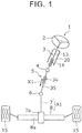
- FIG. 1 is a schematic structural diagram of a vehicle steering system including an intermediate shaft to which a spline telescopic shaft according to the embodiment is applied.
- a vehicle steering system 1 includes a steering shaft 3, an intermediate shaft 5, a pinion shaft 7, and a rack shaft 8.
- the steering shaft 3 is coupled to a steering member 2 such as a steering wheel.
- the intermediate shaft 5 serves as the spline telescopic shaft coupled to the steering shaft 3 through a universal joint 4.
- the pinion shaft 7 is coupled to the intermediate shaft 5 through a universal joint 6.
- the rack shaft 8 serves as a steering operation shaft including a rack 8a that meshes with a pinion 7a provided near the end of the pinion shaft 7.
- a steering operation mechanism A1 is constructed of a rack and pinion mechanism including the pinion shaft 7 and the rack shaft 8.
- the rack shaft 8 is supported by a housing (not illustrated) so as to be movable in an axial direction along a lateral direction of a vehicle (direction along the drawing sheet). Although illustration is omitted, the ends of the rack shaft 8 are coupled to corresponding steered wheels through corresponding tie rods and corresponding knuckle arms.
- the steering shaft 3 includes an upper shaft 13 and a lower shaft 14 fitted together by spline coupling so as to be rotatable together and slidable relative to each other in an axial direction.
- One of the upper shaft 13 and the lower shaft 14 is an inner shaft, and the other is a tubular outer shaft.
- the upper shaft 13 and the lower shaft 14 are supported on a vehicle body through a steering column 20.
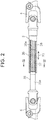
- FIG. 2 is a partially cutaway side view of the intermediate shaft 5 according to the embodiment.
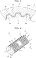
- FIG. 3 is a sectional view illustrating the sectional profile of a part of the intermediate shaft 5 according to the embodiment. Specifically, FIG. 3 is a sectional view illustrating a cutting plane including a line III-III in FIG. 2 .
- the intermediate shaft 5 serving as the spline telescopic shaft is formed by spline-fitting an inner shaft 35 and a tubular outer shaft 36 so that the inner shaft 35 and the outer shaft 36 are slidable along an axial direction X1 and a torque is transmissible therebetween.
- One of the inner shaft 35 and the outer shaft 36 is an upper shaft, and the other is a lower shaft.
- the outer shaft 36 is coupled to the universal joint 4 as the upper shaft, and the inner shaft 35 is coupled to the universal joint 6 as the lower shaft.
- spline telescopic shaft is applied to the intermediate shaft 5.
- the spline telescopic shaft of the present invention may be applied to the steering shaft 3, and the steering shaft 3 may exert a telescopic adjustment function and a shock absorbing function.
- the spline telescopic shaft of the present invention may be applied to an electric or hydraulic power steering system.
- An outer peripheral surface 35a of the inner shaft 35 is provided with an external spline 37.
- An inner peripheral surface 36a of the outer shaft 36 is provided with an internal spline 38.
- the external spline 37 and the internal spline 38 are slidable while being fitted together.
- the inner shaft 35 and the outer shaft 36 move relative to each other, such that the entire intermediate shaft 5 extends or contracts.
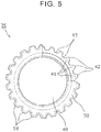
- FIG. 4 is a perspective view illustrating the inner shaft 35 according to the embodiment.
- FIG. 5 is a plan view of the inner shaft 35 according to the embodiment that is viewed in the axial direction.
- FIG. 6 is a side view illustrating the inner shaft 35 according to the embodiment.
- a resin layer 50 provided on the inner shaft 35 is partially omitted.
- the resin layer 50 continuously covers the outer peripheral surface of a shaft body 40 so as to cover the entire circumference of the shaft body 40.
- the inner shaft 35 includes the shaft body 40 and the resin layer 50.
- the shaft body 40 is an elongated member extending along the axial direction X1.
- the shaft body 40 is made of a metal that is relatively light in terms of specific gravity.
- the shaft body 40 is integrally formed by using aluminum or an aluminum alloy.
- a plurality of external teeth 41 are provided on the outer peripheral surface of one end of the shaft body 40.
- the external teeth 41 are radially provided about an axis center of the shaft body 40.
- the number of external teeth 41 to be provided in a circumferential direction may be two or more, but may be four or more from the viewpoint of achieving stable torque transmission.
- the external teeth 41 extend along the axial direction X1.
- a plurality of tooth spaces 43 each provided between the external teeth 41 in the circumferential direction also extend along the axial direction X1.
- a plurality of toothless portions 44, 45, and 46 are provided in tip surfaces 42 of the external teeth 41.
- the toothless portion 44 is arranged closest to the distal end of the shaft body 40.
- the toothless portion 46 is arranged closest to the other end of the shaft body 40.
- the toothless portion 45 is arranged between the toothless portion 44 and the toothless portion 46.
- the lengths of the toothless portion 44 and the toothless portion 46 in the axial direction X1 are equal.
- the length of the toothless portion 45 in the axial direction X1 is larger than the length of the toothless portion 44 in the axial direction X1.
- the toothless portions 44, 45, and 46 are formed by cutting the external teeth 41 in a range from the tip surfaces 42 of the external teeth 41 to the bottom lands of the tooth spaces 43. That is, the bottom surfaces of the toothless portions 44, 45, and 46 are flush with the bottom lands of the tooth spaces 43.
- the toothless portions 44 of the external teeth 41 are arrayed in line over the entire circumference of the shaft body 40.
- the toothless portions 45 of the external teeth 41 are arrayed in line over the entire circumference of the shaft body 40 at positions different from those of the toothless portions 44 in the axial direction X1.
- the toothless portions 46 of the external teeth 41 are arrayed in line over the entire circumference of the shaft body 40 at positions different from those of the toothless portions 44 and the toothless portions 45 in the axial direction X1.
- the resin layer 50 is laminated on the external teeth 41 and the tooth spaces 43 at a substantially uniform thickness.
- the tip end faces of the resin layer 50 corresponding to the external teeth 41 are referred to as tip surfaces 59.
- the resin layer 50 fills the toothless portions 44, 45, and 46 provided in the external teeth 41.
- the outer profile of the entire external spline 37 is substantially uniform along the axial direction X1. That is, each tip surface 59 of the resin layer 50 has a uniform profile along the axial direction X1.
- Portions of the resin layer 50 that fill the toothless portions 44, 45, and 46 are referred to as filling portions 51.
- the thickness of the filling portion 51 is larger than those of portions of the resin layer 50 that are laminated on the external teeth 41 and the tooth spaces 43.
- the filling portions 51 fill the toothless portions 44, 45, and 46, the filling portions 51 are caught on the external teeth 41 in the toothless portions 44, 45, and 46 even if the resin layer 50 may move in the axial direction X1 relative to the shaft body 40. Thus, the movement of the resin layer 50 in the axial direction X1 is restricted, and the resin layer 50 is unlikely to detach from the shaft body 40.
- the outer surfaces of the filling portions 51 are provided with lubricant reservoirs 52 recessed as compared to other portions.
- the lubricant reservoirs 52 are provided at positions corresponding to those of the toothless portions 44, 45, and 46. That is, the lubricant reservoirs 52 are arrayed in a plurality of lines corresponding to the toothless portions 44, 45, and 46 over the entire circumference of the shaft body 40.
- the lubricant reservoirs 52 are successively provided in the tooth flanks of the external spline 37.
- a lubricant is stored in the lubricant reservoir 52.
- the stored lubricant can increase the slidability of the internal spline 38 relative to the external spline 37.
- the lubricant includes a liquid lubricant such as lubricating oil, a semisolid lubricant such as grease, and a solid lubricant composed of a soft metal such as molybdenum disulfide.
- the tooth flanks of the external spline 37 mesh with the tooth flanks of the internal spline 38.
- the slidability of the internal spline 38 relative to the external spline 37 can be increased if the lubricant enters the meshing portions.
- the lubricant reservoirs 52 are successively provided in the tooth flanks of the external spline 37. Therefore, the lubricant can enter the meshing portions.
- FIG. 7 is a flowchart illustrating a flow of the method for manufacturing the intermediate shaft 5 according to the embodiment.
- the shaft body 40 is formed by forming the external teeth 41 on a metal round bar as illustrated in FIG. 5 .
- the external teeth 41 are formed on the outer peripheral surface of the round bar by drawing the round bar.
- the toothless portions 44, 45, and 46 are formed by, for example, cutting the tip surfaces 42 of the external teeth 41 of the shaft body 40 formed in the tooth forming step.
- FIG. 8 and FIG. 9 are sectional views illustrating the condition of the shaft body 40 in the resin layer forming step S3 according to the embodiment.
- FIG. 9 is a sectional view illustrating a cutting plane including a line IX-IX in FIG. 8 .
- one end of the shaft body 40 is housed in a cavity 91 of a mold 90.
- the cavity 91 of the mold 90 has a surface profile conforming to the outer profile of the resin layer 50.
- each receiving surface 92 for the tip surface 42 of the shaft body 40 has a flat profile.
- the receiving surface 92 faces the tip surface 42 at a predetermined distance.
- the receiving surface 92 is a surface for molding the tip surface 59 of the resin layer 50.
- the receiving surface 92 has a uniform profile along the axial direction X1.
- the receiving surface 92 also has a linear profile when viewed in the axial direction.
- the profile is uniform along the axial direction X1.
- the receiving surface 92 also has a curved profile when viewed in the axial direction.
- the profile is uniform along the axial direction X1. That is, the flat profile of the receiving surface 92 means that the entire receiving surface 92 has a uniform profile along the axial direction X1.
- the resin layer forming step S3 when one end of the shaft body 40 is arranged in the cavity 91 of the mold 90, the resin is injected into the cavity 91 for injection molding. Thus, the resin layer 50 that covers the external teeth 41 and the tooth spaces 43 is formed. At this time, the filling portions 51 are formed by filling the toothless portions 44, 45, and 46 with the resin.
- the shaft body 40 including the resin layer 50 is cooled.
- the shaft body 40 may be cooled in still air or by using a cooler.
- the resin layer 50 is cured by the cooling.
- the resin layer 50 shrinks during the cooling.
- the thickness of the filling portion 51 of the resin layer 50 is larger than those of portions of the resin layer 50 that are laminated on the external teeth 41. That is, the shrinkage of the filling portion 51 is larger than those of the portions laminated on the external teeth 41. Therefore, the outer surface of the filling portion 51 is recessed as compared to the surrounding portions.
- the recess serves as the lubricant reservoir 52 (see FIG. 6 ).
- the shaft body 40 including the resin layer 50 serves as the inner shaft 35 including the external spline 37.
- the inner shaft 35 is attached to the outer shaft 36 including the internal spline 38 provided on the inner peripheral surface. Specifically, lubricating oil is applied to at least one of the outer surface of the external spline 37 and the inner surface of the internal spline 38. Then, the inner shaft 35 is attached to the outer shaft 36 by inserting and fitting the external spline 37 of the inner shaft 35 into the internal spline 38 of the outer shaft 36. After the attachment, the lubricating oil is located between the external spline 37 and the internal spline 38. In particular, the lubricating oil is stored in the lubricant reservoirs 52 of the external spline 37. Therefore, the relative slidability between the external spline 37 and the internal spline 38 can be maintained stably over a long period. Thus, the intermediate shaft 5 is completed.
- a part of the resin layer 50 formed by injection molding fills the toothless portions 44, 45, and 46 provided in the external teeth 41 of the shaft body 40. Since the filling portions 51 of the resin layer 50 fill the toothless portions 44, 45, and 46, the filling portions 51 are caught on the external teeth 41 in the toothless portions 44, 45, and 46 even if the resin layer 50 may move in the axial direction X1 relative to the shaft body 40. Thus, the movement of the resin layer 50 in the axial direction X1 is restricted. Accordingly, retention on the shaft body 40 can be maintained even in the case of the resin layer 50 formed by injection molding.
- portions of the resin layer 50 corresponding to the toothless portions 44, 45, and 46 are recessed as compared to other portions when cured.
- the recesses serve as the lubricant reservoirs 52. That is, the lubricant reservoirs 52 can definitely be formed during the curing without cutting or melting the resin layer 50. Therefore, the lubricant reservoirs 52 can be formed without performing additional work (machining).
- the lubricant reservoirs may be formed such that protrusions for forming the lubricant reservoirs be provided in the cavity of the mold.
- the protrusions are obstacles that make it difficult to pull out the shaft body from the mold in the axial direction after the resin layer is cured. Therefore, it is necessary to prepare the mold so that the mold is splittable into many parts. This case is not preferable because the mold is complicated.
- This embodiment is advantageous in that the lubricant reservoirs 52 can be formed without providing the protrusions for the lubricant reservoirs in the cavity of the mold.
- the shaft body 40 is made of aluminum or an aluminum alloy.
- Aluminum or an aluminum alloy is light in weight. By employing aluminum or an aluminum alloy for the shaft body 40, the weight of the spline telescopic shaft can be reduced. However, the melting point of aluminum or an aluminum alloy is relatively low. If aluminum or an aluminum alloy is employed for the shaft body 40 and the resin layer is laminated by fluidized-bed coating, the strength is likely to decrease due to influence of heat generated during the fluidized-bed coating. With the method for manufacturing the spline telescopic shaft and with the spline telescopic shaft, the decrease in the strength of the shaft body 40 made of aluminum or an aluminum alloy can be suppressed because the resin layer 50 is formed by injection molding.
- the toothless portions 44, 45, and 46 are provided in all the tip surfaces 42 of the external teeth 41 so as to be arrayed over the entire circumference of the shaft body 40.
- the lubricant reservoirs 52 are provided at portions of the resin layer 50 corresponding to all the toothless portions 44, 45, and 46.
- the lubricant reservoirs 52 are provided at portions corresponding to all the toothless portions 44, 45, and 46 arrayed over the entire circumference of the shaft body 40, the lubricating oil stored in the lubricant reservoirs 52 can be distributed over the entire circumference of the shaft body 40.
- the relative slidability between the external spline 37 and the internal spline 38 can further be stabilized.
- the toothless portions 44, 45, and 46 are provided in all the tip surfaces 42 of the external teeth 41 at a plurality of positions spaced away from each other in the axial direction X1 of the shaft body 40 so as to be arrayed over the entire circumference of the shaft body 40.
- the lubricant reservoirs 52 are provided at portions corresponding to all the toothless portions 44, 45, and 46 arrayed in a plurality of lines over the entire circumference of the shaft body 40, the lubricating oil can be retained at a plurality of positions in the axial direction X1.
- the relative slidability between the external spline 37 and the internal spline 38 can further be stabilized.
- FIG. 10 is a perspective view illustrating a toothless portion 44a of a shaft body 40a according to Modified Example 1.
- FIG. 11 is a sectional view illustrating the toothless portion 44a and its surrounding structure according to Modified Example 1.
- the toothless portion 44a provided in the shaft body 40a according to Modified Example 1 is formed by pressing each external tooth 41a. Therefore, a part of the external tooth 41a is plastically deformed. Thus, a bottom 47a of the toothless portion 44a laterally protrudes from the tooth flanks of the external tooth 41a. Those portions are referred to as protruding portions 49a.
- protruding portions 49a In Modified Example 1, description is given of an exemplary case where the protruding portions 49a protrude from the respective tooth flanks of the external tooth 41a.
- the protruding portion 49a may protrude from one tooth flank alone.
- the protrusion amount of the protruding portion 49a is smaller than the thickness of a resin layer 50a. Thus, the entire protruding portion 49a is embedded in the resin layer 50a.
- FIG. 11 illustrates a state in which the external tooth 41a meshes with the internal spline 38.
- a long dashed double-short dashed line in FIG. 11 represents the outer profile of the external tooth 41a at a portion that is not pressed.
- the resin layer 50a is evenly laminated.
- the resin layer 50a overlaps the protruding portions 49a when viewed in the axial direction (portions represented by dashed-line hatching in FIG. 11 ).
- the resin layer 50a is caught on the protruding portions 49a, and the movement of the resin layer 50a in the axial direction X1 is restricted.
- a lubricant reservoir 52a recessed as compared to other portions is formed at a portion of the resin layer 50a (filling portion 51a) corresponding to the toothless portion 44a.
- dot hatching represents a state in which lubricating oil G is stored in the lubricant reservoir 52a.
- lubricating oil is also applied to the surface of the resin layer 50a and the surface of the internal spline 38 in actuality.
- the position of a bottom surface 48a of the bottom 47a may be substantially the same position as those of tip surfaces 38a of the internal spline 38.
- the lubricant reservoir 52a to be formed by the presence of the toothless portion 44a can be formed to have a size corresponding to those of the tooth flanks where the inner shaft 35 and the outer shaft 36 slide in contact with each other. Accordingly, the lubricating oil G stored in the lubricant reservoir 52a can securely be distributed over the tooth flanks of the internal spline 38.
- a shaft body 40a including external teeth 41a with no toothless portions 44a is prepared first.
- the toothless portions 44a are formed by, for example, pressing tip surfaces 42a of the external teeth 41a of the shaft body 40a. At this time, the tip surface 42a of each external tooth 41a is plastically deformed. Thus, a part of the bottom 47a of the toothless portion 44a laterally protrudes from the tooth flanks of the external tooth 41a as the protruding portions 49a.
- the part of the bottom 47a of the toothless portion 44a is caught on the resin layer 50a as the protruding portions 49a.
- the movement of the resin layer 50a in the axial direction X1 can be restricted. Accordingly, retention on the shaft body 40a can be maintained more securely even in the case of the resin layer 50a formed by injection molding.
- FIG. 12 is a perspective view schematically illustrating an inner shaft 35b according to Modified Example 2.
- toothless portions 44b and lubricant reservoirs 52b are schematically represented by long dashed double-short dashed lines so that their arrangement positions coincide with each other.
- the toothless portions 44b and the lubricant reservoirs 52b are provided in a plurality of lines along a circumferential direction of a shaft body 40b.
- the toothless portions 44b are provided in at least two tip surfaces 42b of external teeth 41b at a plurality of positions spaced away from each other in the axial direction X1 of the shaft body 40b so as to be arrayed in the circumferential direction.
- the lubricant reservoirs 52b are provided at portions of a resin layer 50b corresponding to all the toothless portions 44b.
- each array of the toothless portions 44b and the lubricant reservoirs 52b is provided in an area corresponding to a semiperimeter of the shaft body 40b. If a first array is an odd-numbered array and a second array is an even-numbered array from the distal end of the shaft body 40b in the axial direction X1, the second array is located so as not to overlap the first array in the axial direction X1.
- the toothless portions 44b are provided in at least two tip surfaces 42b of the external teeth 41b at a plurality of positions spaced away from each other in the axial direction X1 of the shaft body 40b so as to be arrayed in the circumferential direction.
- the number of processes for forming the toothless portions can be reduced as compared to the case where the toothless portions are formed over the entire circumference. If the first arrays and the second arrays are alternately provided as described above, lubricating oil stored in the lubricant reservoirs 52b can be distributed over the entire circumference of the shaft body 40b.
- the resin layer 50 is provided on the shaft body 40 of the inner shaft 35.
- the resin layer may be provided on the outer shaft.
- description is given of a case where the resin layer is provided on a tubular body of the outer shaft.
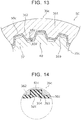
- FIG. 13 is a sectional view illustrating the sectional profile of a part of an intermediate shaft 5C according to Modified Example 3. Specifically, FIG. 13 corresponds to FIG. 3 .
- an inner shaft 35c according to Modified Example 3 does not include the resin layer, and a resin layer 50c is provided on an outer shaft 36c.
- the outer shaft 36c includes a tubular body 361 and the resin layer 50c.
- the tubular body 361 is a cylindrical body.
- a plurality of internal teeth 362 extending in the axial direction X1 are formed on the inner peripheral surface of the tubular body 361.
- the internal teeth 362 are radially provided about an axis center of the tubular body 361.
- FIG. 14 is a sectional view illustrating a cutting plane including a line XIV-XIV in FIG. 13 . As illustrated in FIG. 14 , at least one toothless portion 364 is formed in a tip surface 363 of each of the internal teeth 362.
- the resin layer 50c is laminated on an inner peripheral surface 369 of the outer shaft 36c so as to cover the entire inner peripheral surface 369.
- the resin layer 50c fills the toothless portions 364 provided in the internal teeth 362. Portions of the resin layer 50c that fill the toothless portions 364 are referred to as filling portions 51c.
- the thickness of the filling portion 51c is larger than those of portions of the resin layer 50c that are laminated on the internal teeth 362. Since the filling portions 51c fill the toothless portions 364, the filling portions 51c are caught on the internal teeth 362 in the toothless portions 364 even if the resin layer 50c may move in the axial direction X1 relative to the tubular body 361. Thus, the movement of the resin layer 50c in the axial direction X1 is restricted, and the resin layer 50c is unlikely to detach from the tubular body 361.
- the outer surfaces of the filling portions 51c are provided with lubricant reservoirs 52c recessed as compared to other portions. Specifically, the lubricant reservoirs 52c are provided at positions corresponding to those of the toothless portions 364. For example, a lubricant is stored in the lubricant reservoir 52c. The stored lubricant can increase the slidability of the internal spline 38 relative to the external spline 37.
- the outer shaft 36c according to Modified Example 3 can be formed through steps similar to the steps for manufacturing the inner shaft 35 described above (tooth forming step S1, toothless portion forming step S2, resin layer forming step S3, and cooling step S4).
- the present invention is not limited to the embodiment.
- the shaft body 40 is made of aluminum.
- the shaft body 40 may be made of other metals.
- the lubricant reservoir is formed at a portion of the resin layer corresponding to the toothless portion.
- the toothless portions 44, 45, and 46 are formed in the shaft body 40 including the external teeth 41 formed in advance.
- the external teeth may be formed after recesses serving as the toothless portions are formed in a shaft body including no external teeth.
- the present invention encompasses embodiments attained by various modifications conceivable by persons skilled in the art to the embodiment, and embodiments attained by arbitrarily combining the constituent elements and functions of the embodiment and the modified examples without departing from the spirit of the present invention.
- the present invention is applicable to a spline telescopic shaft including an external spline that has a resin layer.
Landscapes
- Engineering & Computer Science (AREA)
- Mechanical Engineering (AREA)
- General Engineering & Computer Science (AREA)
- Manufacturing & Machinery (AREA)
- Chemical & Material Sciences (AREA)
- Combustion & Propulsion (AREA)
- Transportation (AREA)
- Ocean & Marine Engineering (AREA)
- Shafts, Cranks, Connecting Bars, And Related Bearings (AREA)
- Steering Controls (AREA)
- Power Steering Mechanism (AREA)
Abstract
Description
- The present invention relates to a method for manufacturing a spline telescopic shaft, and to a spline telescopic shaft.
- Japanese Unexamined Patent Application Publication No.
2014-238173 JP 2014-238173 A - Various metals may be used as materials for forming the inner shaft. Depending on the metals, the strength may decrease due to influence of heat generated during the fluidized bed coating. In view of the circumstances, the resin layer may be formed by injection molding. When the resin layer is formed by injection molding, the resin layer may detach from the inner shaft due to low adhesion to the inner shaft. Even if the recesses serving as lubricant reservoirs are formed in this resin layer by laser beam machining, the resin layer including the recesses may peel off due to the low adhesion. Similar problems may arise in a case where the resin layer is provided on the outer shaft.
- The present invention provides a method for manufacturing a spline telescopic shaft, and a spline telescopic shaft in which lubricant reservoirs are easily formed while maintaining retention of a resin layer on an inner shaft or an outer shaft.
- A method for manufacturing a spline telescopic shaft according to a first aspect of the present invention is a method for manufacturing a spline telescopic shaft including an inner shaft provided with an external spline on an outer peripheral surface of the inner shaft, and an outer shaft provided with an internal spline on an inner peripheral surface of the outer shaft and configured such that the external spline of the inner shaft slides in an axial direction relative to the internal spline. The method includes a toothless portion forming step, a resin layer forming step, and a cooling step. The toothless portion forming step is a step of forming a toothless portion in one of an external tooth provided on an outer peripheral surface of a shaft body included in the inner shaft to extend in the axial direction and an internal tooth provided on an inner peripheral surface of a tubular body included in the outer shaft to extend in the axial direction. The resin layer forming step is a step of forming a resin layer, which covers one of the external tooth and the internal tooth and fills the toothless portion, by arranging one of the shaft body including the toothless portion and the tubular body including the toothless portion in a mold including a cavity and injecting a resin into the cavity. The cavity is included in a flat receiving surface that faces tooth flanks of one of the external tooth of the shaft body including the toothless portion and the internal tooth of the tubular body including the toothless portion. The cooling step is a step of cooling one of the shaft body including the resin layer and the tubular body including the resin layer to form a lubricant reservoir such that a portion of the resin layer corresponding to the toothless portion is recessed as compared to other portions.
- A spline telescopic shaft according to a second aspect of the present invention includes an inner shaft provided with an external spline on an outer peripheral surface of the inner shaft, and an outer shaft provided with an internal spline on an inner peripheral surface of the outer shaft and configured such that the external spline of the inner shaft slides relative to the internal spline. The inner shaft includes a shaft body including an external tooth serving as at least a part of the external spline on the outer peripheral surface. The outer shaft includes a tubular body including an internal tooth serving as at least a part of the internal spline on the inner peripheral surface. One of the shaft body and the tubular body includes a resin layer, which covers one of the external tooth and the internal tooth. A toothless portion filled with the resin layer is provided in one of the external tooth covered with the resin layer and the internal tooth covered with the resin layer. A portion of the resin layer corresponding to the toothless portion is a lubricant reservoir recessed as compared to other portions.
- According to the present invention, it is possible to provide the method for manufacturing a spline telescopic shaft, and the spline telescopic shaft in which the lubricant reservoirs are easily formed while maintaining the retention of the resin layer on the inner shaft or the outer shaft.
- Features, advantages, and technical and industrial significance of exemplary embodiments of the invention will be described below with reference to the accompanying drawings, in which like numerals denote like elements, and wherein:
-
FIG. 1 is a schematic structural diagram of a vehicle steering system including an intermediate shaft to which a spline telescopic shaft according to an embodiment is applied; -
FIG. 2 is a partially cutaway side view of the intermediate shaft according to the embodiment; -
FIG. 3 is a sectional view illustrating the sectional profile of a part of the intermediate shaft according to the embodiment; -
FIG. 4 is a perspective view illustrating an inner shaft according to the embodiment; -
FIG. 5 is a plan of the inner shaft according to the embodiment that is viewed in an axial direction; -
FIG. 6 is a side view illustrating the inner shaft according to the embodiment; -
FIG. 7 is a flowchart illustrating a flow of a method for manufacturing the intermediate shaft according to the embodiment; -
FIG. 8 is a sectional view illustrating the condition of a shaft body in a resin layer forming step according to the embodiment; -
FIG. 9 is a sectional view illustrating a cutting plane including a line IX-IX inFIG. 8 , illustrating the condition of the shaft body in the resin layer forming step according to the embodiment; -
FIG. 10 is a perspective view illustrating a toothless portion of a shaft body according to Modified Example 1; -
FIG. 11 is a sectional view illustrating the toothless portion and its surrounding structure according to Modified Example 1; -
FIG. 12 is a perspective view schematically illustrating an inner shaft according to Modified Example 2; -
FIG. 13 is a sectional view illustrating the sectional profile of a part of an intermediate shaft according to Modified Example 3; and -
FIG. 14 is a sectional view illustrating a cutting plane including a line XIV-XIV inFIG. 13 . - An embodiment is described below in detail with reference to the drawings. The embodiment described below demonstrates a comprehensive or specific example. Numerical values, shapes, materials, constituent elements, arrangement positions and connection forms of the constituent elements, and the like described in the following embodiment are examples, and are not intended to limit the present invention. Among the constituent elements of the following embodiment, constituent elements that are not described in independent claims that demonstrate the broadest concept are described as optional constituent elements.
- The drawings are schematic drawings in which elements are emphasized, omitted, or adjusted in their proportions as appropriate to demonstrate the present invention. Shapes, positional relationships, or proportions may differ from actual shapes, positional relationships, or proportions.
-
FIG. 1 is a schematic structural diagram of a vehicle steering system including an intermediate shaft to which a spline telescopic shaft according to the embodiment is applied. As illustrated inFIG. 1 , avehicle steering system 1 includes asteering shaft 3, anintermediate shaft 5, a pinion shaft 7, and a rack shaft 8. Thesteering shaft 3 is coupled to a steering member 2 such as a steering wheel. Theintermediate shaft 5 serves as the spline telescopic shaft coupled to thesteering shaft 3 through auniversal joint 4. The pinion shaft 7 is coupled to theintermediate shaft 5 through auniversal joint 6. The rack shaft 8 serves as a steering operation shaft including arack 8a that meshes with apinion 7a provided near the end of the pinion shaft 7. - A steering operation mechanism A1 is constructed of a rack and pinion mechanism including the pinion shaft 7 and the rack shaft 8. The rack shaft 8 is supported by a housing (not illustrated) so as to be movable in an axial direction along a lateral direction of a vehicle (direction along the drawing sheet). Although illustration is omitted, the ends of the rack shaft 8 are coupled to corresponding steered wheels through corresponding tie rods and corresponding knuckle arms.
- The
steering shaft 3 includes anupper shaft 13 and alower shaft 14 fitted together by spline coupling so as to be rotatable together and slidable relative to each other in an axial direction. One of theupper shaft 13 and thelower shaft 14 is an inner shaft, and the other is a tubular outer shaft. Theupper shaft 13 and thelower shaft 14 are supported on a vehicle body through asteering column 20. -
FIG. 2 is a partially cutaway side view of theintermediate shaft 5 according to the embodiment.FIG. 3 is a sectional view illustrating the sectional profile of a part of theintermediate shaft 5 according to the embodiment. Specifically,FIG. 3 is a sectional view illustrating a cutting plane including a line III-III inFIG. 2 . - As illustrated in
FIG. 1 to FIG. 3 , theintermediate shaft 5 serving as the spline telescopic shaft is formed by spline-fitting aninner shaft 35 and a tubularouter shaft 36 so that theinner shaft 35 and theouter shaft 36 are slidable along an axial direction X1 and a torque is transmissible therebetween. One of theinner shaft 35 and theouter shaft 36 is an upper shaft, and the other is a lower shaft. In this embodiment, theouter shaft 36 is coupled to theuniversal joint 4 as the upper shaft, and theinner shaft 35 is coupled to theuniversal joint 6 as the lower shaft. - In this embodiment, description is given of a case where the spline telescopic shaft is applied to the
intermediate shaft 5. The spline telescopic shaft of the present invention may be applied to thesteering shaft 3, and thesteering shaft 3 may exert a telescopic adjustment function and a shock absorbing function. In this embodiment, description is given of a case where thevehicle steering system 1 is a manual steering system. The spline telescopic shaft of the present invention may be applied to an electric or hydraulic power steering system. - An outer
peripheral surface 35a of theinner shaft 35 is provided with anexternal spline 37. An innerperipheral surface 36a of theouter shaft 36 is provided with aninternal spline 38. Theexternal spline 37 and theinternal spline 38 are slidable while being fitted together. Theinner shaft 35 and theouter shaft 36 move relative to each other, such that the entireintermediate shaft 5 extends or contracts. - Next, the
inner shaft 35 is described in detail. -
FIG. 4 is a perspective view illustrating theinner shaft 35 according to the embodiment.FIG. 5 is a plan view of theinner shaft 35 according to the embodiment that is viewed in the axial direction.FIG. 6 is a side view illustrating theinner shaft 35 according to the embodiment. InFIG. 4 to FIG. 6 , aresin layer 50 provided on theinner shaft 35 is partially omitted. In actuality, theresin layer 50 continuously covers the outer peripheral surface of ashaft body 40 so as to cover the entire circumference of theshaft body 40. - As illustrated in
FIG. 4 to FIG. 6 , theinner shaft 35 includes theshaft body 40 and theresin layer 50. Theshaft body 40 is an elongated member extending along the axial direction X1. Theshaft body 40 is made of a metal that is relatively light in terms of specific gravity. Specifically, theshaft body 40 is integrally formed by using aluminum or an aluminum alloy. A plurality ofexternal teeth 41 are provided on the outer peripheral surface of one end of theshaft body 40. Theexternal teeth 41 are radially provided about an axis center of theshaft body 40. The number ofexternal teeth 41 to be provided in a circumferential direction may be two or more, but may be four or more from the viewpoint of achieving stable torque transmission. - The
external teeth 41 extend along the axial direction X1. Thus, a plurality oftooth spaces 43 each provided between theexternal teeth 41 in the circumferential direction also extend along the axial direction X1. - A plurality of
toothless portions external teeth 41. Thetoothless portion 44 is arranged closest to the distal end of theshaft body 40. Thetoothless portion 46 is arranged closest to the other end of theshaft body 40. Thetoothless portion 45 is arranged between thetoothless portion 44 and thetoothless portion 46. The lengths of thetoothless portion 44 and thetoothless portion 46 in the axial direction X1 are equal. The length of thetoothless portion 45 in the axial direction X1 is larger than the length of thetoothless portion 44 in the axial direction X1. Thetoothless portions external teeth 41 in a range from the tip surfaces 42 of theexternal teeth 41 to the bottom lands of thetooth spaces 43. That is, the bottom surfaces of thetoothless portions tooth spaces 43. - The
toothless portions 44 of theexternal teeth 41 are arrayed in line over the entire circumference of theshaft body 40. Thetoothless portions 45 of theexternal teeth 41 are arrayed in line over the entire circumference of theshaft body 40 at positions different from those of thetoothless portions 44 in the axial direction X1. Thetoothless portions 46 of theexternal teeth 41 are arrayed in line over the entire circumference of theshaft body 40 at positions different from those of thetoothless portions 44 and thetoothless portions 45 in the axial direction X1. - The
resin layer 50 is laminated on theexternal teeth 41 and thetooth spaces 43 at a substantially uniform thickness. The tip end faces of theresin layer 50 corresponding to theexternal teeth 41 are referred to as tip surfaces 59. Theresin layer 50 fills thetoothless portions external teeth 41. With theresin layer 50, the outer profile of the entireexternal spline 37 is substantially uniform along the axial direction X1. That is, eachtip surface 59 of theresin layer 50 has a uniform profile along the axial direction X1. Portions of theresin layer 50 that fill thetoothless portions portions 51. The thickness of the fillingportion 51 is larger than those of portions of theresin layer 50 that are laminated on theexternal teeth 41 and thetooth spaces 43. Since the fillingportions 51 fill thetoothless portions portions 51 are caught on theexternal teeth 41 in thetoothless portions resin layer 50 may move in the axial direction X1 relative to theshaft body 40. Thus, the movement of theresin layer 50 in the axial direction X1 is restricted, and theresin layer 50 is unlikely to detach from theshaft body 40. - As illustrated in
FIG. 6 , the outer surfaces of the fillingportions 51 are provided withlubricant reservoirs 52 recessed as compared to other portions. Specifically, thelubricant reservoirs 52 are provided at positions corresponding to those of thetoothless portions lubricant reservoirs 52 are arrayed in a plurality of lines corresponding to thetoothless portions shaft body 40. Thus, thelubricant reservoirs 52 are successively provided in the tooth flanks of theexternal spline 37. For example, a lubricant is stored in thelubricant reservoir 52. The stored lubricant can increase the slidability of theinternal spline 38 relative to theexternal spline 37. The lubricant includes a liquid lubricant such as lubricating oil, a semisolid lubricant such as grease, and a solid lubricant composed of a soft metal such as molybdenum disulfide. - As illustrated in
FIG. 3 , the tooth flanks of theexternal spline 37 mesh with the tooth flanks of theinternal spline 38. The slidability of theinternal spline 38 relative to theexternal spline 37 can be increased if the lubricant enters the meshing portions. As described above, thelubricant reservoirs 52 are successively provided in the tooth flanks of theexternal spline 37. Therefore, the lubricant can enter the meshing portions. - Next, description is given of a method for manufacturing the
intermediate shaft 5 serving as the spline telescopic shaft.FIG. 7 is a flowchart illustrating a flow of the method for manufacturing theintermediate shaft 5 according to the embodiment. - In a tooth forming step S1, the
shaft body 40 is formed by forming theexternal teeth 41 on a metal round bar as illustrated inFIG. 5 . Specifically, theexternal teeth 41 are formed on the outer peripheral surface of the round bar by drawing the round bar. - In a toothless portion forming step S2, the
toothless portions external teeth 41 of theshaft body 40 formed in the tooth forming step. - In a resin layer forming step S3, the
resin layer 50 is formed by injection molding of theshaft body 40 using a resin.FIG. 8 andFIG. 9 are sectional views illustrating the condition of theshaft body 40 in the resin layer forming step S3 according to the embodiment.FIG. 9 is a sectional view illustrating a cutting plane including a line IX-IX inFIG. 8 . As illustrated inFIG. 8 andFIG. 9 , in the resin layer forming step S3, one end of theshaft body 40 is housed in acavity 91 of amold 90. Thecavity 91 of themold 90 has a surface profile conforming to the outer profile of theresin layer 50. In thecavity 91, each receivingsurface 92 for thetip surface 42 of theshaft body 40 has a flat profile. - The receiving
surface 92 faces thetip surface 42 at a predetermined distance. The receivingsurface 92 is a surface for molding thetip surface 59 of theresin layer 50. The receivingsurface 92 has a uniform profile along the axial direction X1. For example, if thetip surface 59 of theresin layer 50 has a linear profile when viewed in the axial direction, the receivingsurface 92 also has a linear profile when viewed in the axial direction. The profile is uniform along the axial direction X1. If thetip surface 59 of theresin layer 50 has a curved profile when viewed in the axial direction, the receivingsurface 92 also has a curved profile when viewed in the axial direction. The profile is uniform along the axial direction X1. That is, the flat profile of the receivingsurface 92 means that the entire receivingsurface 92 has a uniform profile along the axial direction X1. - In the resin layer forming step S3, when one end of the
shaft body 40 is arranged in thecavity 91 of themold 90, the resin is injected into thecavity 91 for injection molding. Thus, theresin layer 50 that covers theexternal teeth 41 and thetooth spaces 43 is formed. At this time, the fillingportions 51 are formed by filling thetoothless portions - In a cooling step S4 illustrated in
FIG. 7 , theshaft body 40 including theresin layer 50 is cooled. Theshaft body 40 may be cooled in still air or by using a cooler. Theresin layer 50 is cured by the cooling. Theresin layer 50 shrinks during the cooling. The thickness of the fillingportion 51 of theresin layer 50 is larger than those of portions of theresin layer 50 that are laminated on theexternal teeth 41. That is, the shrinkage of the fillingportion 51 is larger than those of the portions laminated on theexternal teeth 41. Therefore, the outer surface of the fillingportion 51 is recessed as compared to the surrounding portions. The recess serves as the lubricant reservoir 52 (seeFIG. 6 ). When theresin layer 50 is cured, theshaft body 40 is released from themold 90. Theshaft body 40 including theresin layer 50 serves as theinner shaft 35 including theexternal spline 37. - In an assembling step S5, the
inner shaft 35 is attached to theouter shaft 36 including theinternal spline 38 provided on the inner peripheral surface. Specifically, lubricating oil is applied to at least one of the outer surface of theexternal spline 37 and the inner surface of theinternal spline 38. Then, theinner shaft 35 is attached to theouter shaft 36 by inserting and fitting theexternal spline 37 of theinner shaft 35 into theinternal spline 38 of theouter shaft 36. After the attachment, the lubricating oil is located between theexternal spline 37 and theinternal spline 38. In particular, the lubricating oil is stored in thelubricant reservoirs 52 of theexternal spline 37. Therefore, the relative slidability between theexternal spline 37 and theinternal spline 38 can be maintained stably over a long period. Thus, theintermediate shaft 5 is completed. - As described above, a part of the
resin layer 50 formed by injection molding fills thetoothless portions external teeth 41 of theshaft body 40. Since the fillingportions 51 of theresin layer 50 fill thetoothless portions portions 51 are caught on theexternal teeth 41 in thetoothless portions resin layer 50 may move in the axial direction X1 relative to theshaft body 40. Thus, the movement of theresin layer 50 in the axial direction X1 is restricted. Accordingly, retention on theshaft body 40 can be maintained even in the case of theresin layer 50 formed by injection molding. - From the viewpoint of manufacture, portions of the
resin layer 50 corresponding to thetoothless portions lubricant reservoirs 52. That is, thelubricant reservoirs 52 can definitely be formed during the curing without cutting or melting theresin layer 50. Therefore, thelubricant reservoirs 52 can be formed without performing additional work (machining). - The lubricant reservoirs may be formed such that protrusions for forming the lubricant reservoirs be provided in the cavity of the mold. In this case, the protrusions are obstacles that make it difficult to pull out the shaft body from the mold in the axial direction after the resin layer is cured. Therefore, it is necessary to prepare the mold so that the mold is splittable into many parts. This case is not preferable because the mold is complicated. This embodiment is advantageous in that the
lubricant reservoirs 52 can be formed without providing the protrusions for the lubricant reservoirs in the cavity of the mold. - The
shaft body 40 is made of aluminum or an aluminum alloy. - Aluminum or an aluminum alloy is light in weight. By employing aluminum or an aluminum alloy for the
shaft body 40, the weight of the spline telescopic shaft can be reduced. However, the melting point of aluminum or an aluminum alloy is relatively low. If aluminum or an aluminum alloy is employed for theshaft body 40 and the resin layer is laminated by fluidized-bed coating, the strength is likely to decrease due to influence of heat generated during the fluidized-bed coating. With the method for manufacturing the spline telescopic shaft and with the spline telescopic shaft, the decrease in the strength of theshaft body 40 made of aluminum or an aluminum alloy can be suppressed because theresin layer 50 is formed by injection molding. - The
toothless portions external teeth 41 so as to be arrayed over the entire circumference of theshaft body 40. Thelubricant reservoirs 52 are provided at portions of theresin layer 50 corresponding to all thetoothless portions - Since the
lubricant reservoirs 52 are provided at portions corresponding to all thetoothless portions shaft body 40, the lubricating oil stored in thelubricant reservoirs 52 can be distributed over the entire circumference of theshaft body 40. Thus, the relative slidability between theexternal spline 37 and theinternal spline 38 can further be stabilized. - The
toothless portions external teeth 41 at a plurality of positions spaced away from each other in the axial direction X1 of theshaft body 40 so as to be arrayed over the entire circumference of theshaft body 40. - Since the
lubricant reservoirs 52 are provided at portions corresponding to all thetoothless portions shaft body 40, the lubricating oil can be retained at a plurality of positions in the axial direction X1. Thus, the relative slidability between theexternal spline 37 and theinternal spline 38 can further be stabilized. - In the embodiment described above, description is given of the exemplary case where the
toothless portions -
FIG. 10 is a perspective view illustrating atoothless portion 44a of ashaft body 40a according to Modified Example 1.FIG. 11 is a sectional view illustrating thetoothless portion 44a and its surrounding structure according to Modified Example 1. - As illustrated in
FIG. 10 andFIG. 11 , thetoothless portion 44a provided in theshaft body 40a according to Modified Example 1 is formed by pressing eachexternal tooth 41a. Therefore, a part of theexternal tooth 41a is plastically deformed. Thus, a bottom 47a of thetoothless portion 44a laterally protrudes from the tooth flanks of theexternal tooth 41a. Those portions are referred to as protrudingportions 49a. In Modified Example 1, description is given of an exemplary case where the protrudingportions 49a protrude from the respective tooth flanks of theexternal tooth 41a. The protrudingportion 49a may protrude from one tooth flank alone. The protrusion amount of the protrudingportion 49a is smaller than the thickness of aresin layer 50a. Thus, the entire protrudingportion 49a is embedded in theresin layer 50a. -
FIG. 11 illustrates a state in which theexternal tooth 41a meshes with theinternal spline 38. A long dashed double-short dashed line inFIG. 11 represents the outer profile of theexternal tooth 41a at a portion that is not pressed. At this portion, theresin layer 50a is evenly laminated. Theresin layer 50a overlaps the protrudingportions 49a when viewed in the axial direction (portions represented by dashed-line hatching inFIG. 11 ). Thus, theresin layer 50a is caught on the protrudingportions 49a, and the movement of theresin layer 50a in the axial direction X1 is restricted. - A
lubricant reservoir 52a recessed as compared to other portions is formed at a portion of theresin layer 50a (fillingportion 51a) corresponding to thetoothless portion 44a. InFIG. 11 , dot hatching represents a state in which lubricating oil G is stored in thelubricant reservoir 52a. Although illustration is omitted inFIG. 11 , lubricating oil is also applied to the surface of theresin layer 50a and the surface of theinternal spline 38 in actuality. - As illustrated in
FIG. 11 , the position of abottom surface 48a of the bottom 47a may be substantially the same position as those oftip surfaces 38a of theinternal spline 38. Thus, thelubricant reservoir 52a to be formed by the presence of thetoothless portion 44a can be formed to have a size corresponding to those of the tooth flanks where theinner shaft 35 and theouter shaft 36 slide in contact with each other. Accordingly, the lubricating oil G stored in thelubricant reservoir 52a can securely be distributed over the tooth flanks of theinternal spline 38. - In the toothless portion forming step S2 for forming the
toothless portion 44a, ashaft body 40a includingexternal teeth 41a with notoothless portions 44a is prepared first. Thetoothless portions 44a are formed by, for example, pressing tip surfaces 42a of theexternal teeth 41a of theshaft body 40a. At this time, thetip surface 42a of eachexternal tooth 41a is plastically deformed. Thus, a part of the bottom 47a of thetoothless portion 44a laterally protrudes from the tooth flanks of theexternal tooth 41a as the protrudingportions 49a. - The part of the bottom 47a of the
toothless portion 44a is caught on theresin layer 50a as the protrudingportions 49a. Thus, the movement of theresin layer 50a in the axial direction X1 can be restricted. Accordingly, retention on theshaft body 40a can be maintained more securely even in the case of theresin layer 50a formed by injection molding. - In the embodiment described above, description is given of the exemplary case where the
toothless portions external teeth 41 so as to be arrayed over the entire circumference of the shaft body. In Modified Example 2, description is given of a case where the toothless portions are provided in at least two tip surfaces of the external teeth. -
FIG. 12 is a perspective view schematically illustrating an inner shaft 35b according to Modified Example 2. InFIG. 12 ,toothless portions 44b andlubricant reservoirs 52b are schematically represented by long dashed double-short dashed lines so that their arrangement positions coincide with each other. As illustrated inFIG. 12 , thetoothless portions 44b and thelubricant reservoirs 52b are provided in a plurality of lines along a circumferential direction of ashaft body 40b. Specifically, thetoothless portions 44b are provided in at least twotip surfaces 42b ofexternal teeth 41b at a plurality of positions spaced away from each other in the axial direction X1 of theshaft body 40b so as to be arrayed in the circumferential direction. Thelubricant reservoirs 52b are provided at portions of aresin layer 50b corresponding to all thetoothless portions 44b. - In
FIG. 12 , each array of thetoothless portions 44b and thelubricant reservoirs 52b is provided in an area corresponding to a semiperimeter of theshaft body 40b. If a first array is an odd-numbered array and a second array is an even-numbered array from the distal end of theshaft body 40b in the axial direction X1, the second array is located so as not to overlap the first array in the axial direction X1. - As described above, the
toothless portions 44b are provided in at least twotip surfaces 42b of theexternal teeth 41b at a plurality of positions spaced away from each other in the axial direction X1 of theshaft body 40b so as to be arrayed in the circumferential direction. With this structure, the number of processes for forming the toothless portions can be reduced as compared to the case where the toothless portions are formed over the entire circumference. If the first arrays and the second arrays are alternately provided as described above, lubricating oil stored in thelubricant reservoirs 52b can be distributed over the entire circumference of theshaft body 40b. - In the embodiment described above, description is given of the exemplary case where the
resin layer 50 is provided on theshaft body 40 of theinner shaft 35. The resin layer may be provided on the outer shaft. In Modified Example 3, description is given of a case where the resin layer is provided on a tubular body of the outer shaft. -
FIG. 13 is a sectional view illustrating the sectional profile of a part of anintermediate shaft 5C according to Modified Example 3. Specifically,FIG. 13 corresponds toFIG. 3 . As illustrated inFIG. 13 , aninner shaft 35c according to Modified Example 3 does not include the resin layer, and aresin layer 50c is provided on anouter shaft 36c. Specifically, theouter shaft 36c includes atubular body 361 and theresin layer 50c. Thetubular body 361 is a cylindrical body. A plurality ofinternal teeth 362 extending in the axial direction X1 are formed on the inner peripheral surface of thetubular body 361. Theinternal teeth 362 are radially provided about an axis center of thetubular body 361. -
FIG. 14 is a sectional view illustrating a cutting plane including a line XIV-XIV inFIG. 13 . As illustrated inFIG. 14 , at least onetoothless portion 364 is formed in atip surface 363 of each of theinternal teeth 362. - The
resin layer 50c is laminated on an innerperipheral surface 369 of theouter shaft 36c so as to cover the entire innerperipheral surface 369. Theresin layer 50c fills thetoothless portions 364 provided in theinternal teeth 362. Portions of theresin layer 50c that fill thetoothless portions 364 are referred to as fillingportions 51c. The thickness of the fillingportion 51c is larger than those of portions of theresin layer 50c that are laminated on theinternal teeth 362. Since the fillingportions 51c fill thetoothless portions 364, the fillingportions 51c are caught on theinternal teeth 362 in thetoothless portions 364 even if theresin layer 50c may move in the axial direction X1 relative to thetubular body 361. Thus, the movement of theresin layer 50c in the axial direction X1 is restricted, and theresin layer 50c is unlikely to detach from thetubular body 361. - The outer surfaces of the filling
portions 51c are provided withlubricant reservoirs 52c recessed as compared to other portions. Specifically, thelubricant reservoirs 52c are provided at positions corresponding to those of thetoothless portions 364. For example, a lubricant is stored in thelubricant reservoir 52c. The stored lubricant can increase the slidability of theinternal spline 38 relative to theexternal spline 37. - The
outer shaft 36c according to Modified Example 3 can be formed through steps similar to the steps for manufacturing theinner shaft 35 described above (tooth forming step S1, toothless portion forming step S2, resin layer forming step S3, and cooling step S4). - Although the method for manufacturing the spline telescopic shaft and the spline telescopic shaft according to the present invention are described above based on the embodiment, the present invention is not limited to the embodiment.
- For example, in the embodiment described above, description is given of the exemplary case where the
shaft body 40 is made of aluminum. Theshaft body 40 may be made of other metals. - In the embodiment described above, description is given of the exemplary case where the plurality of
toothless portions tip surface 42 of oneexternal tooth 41. It is only necessary that at least one toothless portion be provided in thetip surface 42 of oneexternal tooth 41. In the embodiment described above, description is given of the exemplary case where thetoothless portions external teeth 41. It is only necessary that the toothless portions be provided in thetip surface 42 of at least one of theexternal teeth 41. In any case, the lubricant reservoir is formed at a portion of the resin layer corresponding to the toothless portion. - In the embodiment described above, description is given of the exemplary case where the
toothless portions shaft body 40 including theexternal teeth 41 formed in advance. The external teeth may be formed after recesses serving as the toothless portions are formed in a shaft body including no external teeth. - The present invention encompasses embodiments attained by various modifications conceivable by persons skilled in the art to the embodiment, and embodiments attained by arbitrarily combining the constituent elements and functions of the embodiment and the modified examples without departing from the spirit of the present invention.
- The present invention is applicable to a spline telescopic shaft including an external spline that has a resin layer.
Claims (8)
- A method for manufacturing a spline telescopic shaft, the spline telescopic shaft including an inner shaft (35) provided with an external spline (37) on an outer peripheral surface of the inner shaft (35), and an outer shaft (36) provided with an internal spline (38) on an inner peripheral surface of the outer shaft (36) and configured such that the external spline (37) of the inner shaft (35) slides in an axial direction relative to the internal spline (38),
the method characterized by comprising:a toothless portion forming step (S2) of forming a toothless portion in one of an external tooth provided on an outer peripheral surface of a shaft body (40) included in the inner shaft (35) to extend in the axial direction and an internal tooth provided on an inner peripheral surface of a tubular body included in the outer shaft (36) to extend in the axial direction;a resin layer forming step (S3) of forming a resin layer (50), which covers one of the external tooth and the internal tooth and fills the toothless portion, by arranging one of the shaft body (40) including the toothless portion and the tubular body including the toothless portion in a mold including a cavity and injecting a resin into the cavity, the cavity being included in a flat receiving surface that faces tooth flanks of one of the external tooth of the shaft body (40) including the toothless portion and the internal tooth of the tubular body including the toothless portion; anda cooling step (S4) of cooling one of the shaft body (40) including the resin layer (50) and the tubular body including the resin layer (50) to form a lubricant reservoir (52) such that a portion of the resin layer (50) corresponding to the toothless portion is recessed as compared to other portions. - The method for manufacturing the spline telescopic shaft according to claim 1, characterized in that, in the toothless portion forming step (S2), one of the external tooth and the internal tooth is plastically deformed to form the toothless portion and form a protruding portion that protrudes in a lateral direction of the toothless portion.
- The method for manufacturing the spline telescopic shaft according to claim 1 or 2, characterized in that the shaft body (40) is made of aluminum or an aluminum alloy.
- The method for manufacturing the spline telescopic shaft according to any one of claims 1 to 3, characterized in that the lubricant reservoir (52) is formed in the resin layer (50) by forming the toothless portion in the external tooth of the inner shaft (35) in the toothless portion forming step (S2), forming the resin layer (50) on the external tooth of the inner shaft (35) in the resin layer forming step (S3), and cooling the shaft body (40) in the cooling step (S4).
- A spline telescopic shaft characterized by comprising:an inner shaft (35) provided with an external spline (37) on an outer peripheral surface (35a) of the inner shaft (35); andan outer shaft (36) provided with an internal spline (38) on an inner peripheral surface of the outer shaft (36) and configured such that the external spline (37) of the inner shaft (35) slides relative to the internal spline (38), whereinthe inner shaft (35) includes a shaft body (40) including an external tooth serving as at least a part of the external spline (37) on the outer peripheral surface (35a), and the outer shaft (36) includes a tubular body including an internal tooth serving as at least a part of the internal spline (38) on the inner peripheral surface, and whereinone of the shaft body (40) and the tubular body includes a resin layer (50), which covers one of the external tooth and the internal tooth, a toothless portion filled with the resin layer (50) is provided in one of the external tooth covered with the resin layer (50) and the internal tooth covered with the resin layer (50), and a portion of the resin layer (50) corresponding to the toothless portion is a lubricant reservoir (52) recessed as compared to other portions.
- The spline telescopic shaft according to claim 5, characterized in that one of the inner shaft (35) and the outer shaft (36) is provided with a protruding portion that protrudes in a lateral direction of the toothless portion.
- The spline telescopic shaft according to claim 5 or 6, characterized in that the shaft body (40) is made of aluminum or an aluminum alloy.
- The spline telescopic shaft according to any one of claims 5 to 7, characterized in that the inner shaft (35) includes the resin layer (50), and the toothless portion is provided in the external tooth.
Applications Claiming Priority (1)
| Application Number | Priority Date | Filing Date | Title |
|---|---|---|---|
| JP2019042509A JP2020143766A (en) | 2019-03-08 | 2019-03-08 | Manufacturing method of spline telescopic shaft and spline telescopic shaft |
Publications (2)
| Publication Number | Publication Date |
|---|---|
| EP3705256A1 true EP3705256A1 (en) | 2020-09-09 |
| EP3705256B1 EP3705256B1 (en) | 2022-01-12 |
Family
ID=69726525
Family Applications (1)
| Application Number | Title | Priority Date | Filing Date |
|---|---|---|---|
| EP20159527.9A Not-in-force EP3705256B1 (en) | 2019-03-08 | 2020-02-26 | Method for manufacturing spline telescopic shaft and spline telescopic shaft |
Country Status (4)
| Country | Link |
|---|---|
| US (1) | US20200284289A1 (en) |
| EP (1) | EP3705256B1 (en) |
| JP (1) | JP2020143766A (en) |
| CN (1) | CN111661138A (en) |
Families Citing this family (2)
| Publication number | Priority date | Publication date | Assignee | Title |
|---|---|---|---|---|
| CN113085235B (en) * | 2021-05-18 | 2024-10-18 | 北京化工大学 | Stepped tire direct pressure vulcanization inner mold |
| WO2024009794A1 (en) * | 2022-07-04 | 2024-01-11 | 日本精工株式会社 | Steering shaft |
Citations (4)
| Publication number | Priority date | Publication date | Assignee | Title |
|---|---|---|---|---|
| JP2013141957A (en) * | 2012-01-12 | 2013-07-22 | Yamada Seisakusho Co Ltd | Steering shaft |
| JP2014238173A (en) | 2014-07-31 | 2014-12-18 | 株式会社ジェイテクト | Spline telescopic shaft and its manufacturing method |
| DE102016203625B3 (en) * | 2016-03-07 | 2017-03-30 | Thyssenkrupp Ag | Method for producing a variable length steering shaft and injection molding apparatus for carrying out the method |
| DE102016203627B3 (en) * | 2016-03-07 | 2017-03-30 | Thyssenkrupp Ag | Method for producing a variable length steering shaft and injection molding apparatus for carrying out the method |
Family Cites Families (8)
| Publication number | Priority date | Publication date | Assignee | Title |
|---|---|---|---|---|
| US3203201A (en) * | 1963-02-25 | 1965-08-31 | Hyster Co | Slip joint for a mechanical drive |
| US4033020A (en) * | 1975-08-04 | 1977-07-05 | Trw Inc. | Method of making a slip joint |
| FR2432380A1 (en) * | 1978-08-04 | 1980-02-29 | Nacam | Injection moulded coatings for sliding rotary shaft gears - to obtain close tolerance profiles without extensive machining of gears or coatings |
| JP2832934B2 (en) * | 1987-08-22 | 1998-12-09 | アイシン精機株式会社 | Method of manufacturing telescopic shaft |
| DE102009004407B4 (en) * | 2008-01-15 | 2023-02-23 | Dana Automotive Systems Group, Llc | Tubular element with a variety of different sized splines |
| JP5104332B2 (en) * | 2008-01-18 | 2012-12-19 | 日本精工株式会社 | Telescopic shaft manufacturing method and telescopic shaft manufactured by this manufacturing method |
| JP2016148371A (en) * | 2015-02-10 | 2016-08-18 | トヨタ自動車株式会社 | Vehicular shaft |
| CN205686462U (en) * | 2016-06-28 | 2016-11-16 | 长城汽车股份有限公司 | Splined shaft and steering drive axle |
-
2019
- 2019-03-08 JP JP2019042509A patent/JP2020143766A/en active Pending
-
2020
- 2020-02-21 US US16/797,143 patent/US20200284289A1/en not_active Abandoned
- 2020-02-26 EP EP20159527.9A patent/EP3705256B1/en not_active Not-in-force
- 2020-03-05 CN CN202010147593.XA patent/CN111661138A/en active Pending
Patent Citations (4)
| Publication number | Priority date | Publication date | Assignee | Title |
|---|---|---|---|---|
| JP2013141957A (en) * | 2012-01-12 | 2013-07-22 | Yamada Seisakusho Co Ltd | Steering shaft |
| JP2014238173A (en) | 2014-07-31 | 2014-12-18 | 株式会社ジェイテクト | Spline telescopic shaft and its manufacturing method |
| DE102016203625B3 (en) * | 2016-03-07 | 2017-03-30 | Thyssenkrupp Ag | Method for producing a variable length steering shaft and injection molding apparatus for carrying out the method |
| DE102016203627B3 (en) * | 2016-03-07 | 2017-03-30 | Thyssenkrupp Ag | Method for producing a variable length steering shaft and injection molding apparatus for carrying out the method |
Also Published As
| Publication number | Publication date |
|---|---|
| CN111661138A (en) | 2020-09-15 |
| EP3705256B1 (en) | 2022-01-12 |
| JP2020143766A (en) | 2020-09-10 |
| US20200284289A1 (en) | 2020-09-10 |
Similar Documents
| Publication | Publication Date | Title |
|---|---|---|
| JP5867773B2 (en) | Manufacturing method of power transmission shaft | |
| JP5453012B2 (en) | Spline telescopic shaft manufacturing method | |
| GB2316150A (en) | Resin filled telescopic splined connection. | |
| EP3705256B1 (en) | Method for manufacturing spline telescopic shaft and spline telescopic shaft | |
| CN105473882B (en) | Torque transmission axle and its manufacturing method and telescopic shaft with universal joint fork yoke | |
| JP5549658B2 (en) | Telescopic shaft manufacturing method and telescopic shaft manufactured by this manufacturing method | |
| US9403210B2 (en) | Steering column and manufacturing method thereof, and steering apparatus using this steering column | |
| US9566998B2 (en) | Inner shaft for extendable and contractible shaft and manufacturing method thereof | |
| JP5305005B2 (en) | Steering column device | |
| EP2711575A1 (en) | Rotation transmitting apparatus, vehicle steering system, and intermediate shaft | |
| EP2787235A1 (en) | Telescopic shaft | |
| JP2017025964A (en) | Telescopic shaft and manufacturing method thereof | |
| JP5854261B2 (en) | Worm wheel | |
| US20190092370A1 (en) | Method for producing a variable-length steering shaft and injection molding device for carrying out the method | |
| US11325637B2 (en) | Steering system and method for manufacturing the same | |
| WO2015137036A1 (en) | Steering device and method for manufacturing steering device | |
| EP3835173A1 (en) | Telescopic shaft and steering system | |
| JP7648127B2 (en) | Worm wheel, electric power steering device, and method for manufacturing worm wheel | |
| EP4552947A1 (en) | Steering shaft | |
| US6473968B1 (en) | Telescoping joint assembly and a method for making the same | |
| KR101611570B1 (en) | Clearance compansation type rack bush assembly for vehicle | |
| EP3901483A1 (en) | Extendable shaft | |
| JP2006207639A (en) | Manufacturing method of female spline shaft provided with oil sump, and female spline shaft manufactured by this manufacturing method | |
| JP6057139B2 (en) | Manufacturing method of power transmission shaft | |
| JP2025004378A (en) | Telescopic shaft and its manufacturing method |
Legal Events
| Date | Code | Title | Description |
|---|---|---|---|
| PUAI | Public reference made under article 153(3) epc to a published international application that has entered the european phase |
Free format text: ORIGINAL CODE: 0009012 |
|
| STAA | Information on the status of an ep patent application or granted ep patent |
Free format text: STATUS: THE APPLICATION HAS BEEN PUBLISHED |
|
| AK | Designated contracting states |
Kind code of ref document: A1 Designated state(s): AL AT BE BG CH CY CZ DE DK EE ES FI FR GB GR HR HU IE IS IT LI LT LU LV MC MK MT NL NO PL PT RO RS SE SI SK SM TR |
|
| AX | Request for extension of the european patent |
Extension state: BA ME |
|
| STAA | Information on the status of an ep patent application or granted ep patent |
Free format text: STATUS: REQUEST FOR EXAMINATION WAS MADE |
|
| 17P | Request for examination filed |
Effective date: 20210308 |
|
| RBV | Designated contracting states (corrected) |
Designated state(s): AL AT BE BG CH CY CZ DE DK EE ES FI FR GB GR HR HU IE IS IT LI LT LU LV MC MK MT NL NO PL PT RO RS SE SI SK SM TR |
|
| GRAP | Despatch of communication of intention to grant a patent |
Free format text: ORIGINAL CODE: EPIDOSNIGR1 |
|
| STAA | Information on the status of an ep patent application or granted ep patent |
Free format text: STATUS: GRANT OF PATENT IS INTENDED |
|
| RIC1 | Information provided on ipc code assigned before grant |
Ipc: B29C 45/00 20060101AFI20210325BHEP Ipc: F16C 3/03 20060101ALI20210325BHEP |
|
| INTG | Intention to grant announced |
Effective date: 20210421 |
|
| GRAJ | Information related to disapproval of communication of intention to grant by the applicant or resumption of examination proceedings by the epo deleted |
Free format text: ORIGINAL CODE: EPIDOSDIGR1 |
|
| STAA | Information on the status of an ep patent application or granted ep patent |
Free format text: STATUS: REQUEST FOR EXAMINATION WAS MADE |
|
| GRAP | Despatch of communication of intention to grant a patent |
Free format text: ORIGINAL CODE: EPIDOSNIGR1 |
|
| STAA | Information on the status of an ep patent application or granted ep patent |
Free format text: STATUS: GRANT OF PATENT IS INTENDED |
|
| INTC | Intention to grant announced (deleted) | ||
| INTG | Intention to grant announced |
Effective date: 20210831 |
|
| GRAS | Grant fee paid |
Free format text: ORIGINAL CODE: EPIDOSNIGR3 |
|
| GRAA | (expected) grant |
Free format text: ORIGINAL CODE: 0009210 |
|
| STAA | Information on the status of an ep patent application or granted ep patent |
Free format text: STATUS: THE PATENT HAS BEEN GRANTED |
|
| AK | Designated contracting states |
Kind code of ref document: B1 Designated state(s): AL AT BE BG CH CY CZ DE DK EE ES FI FR GB GR HR HU IE IS IT LI LT LU LV MC MK MT NL NO PL PT RO RS SE SI SK SM TR |
|
| RAP3 | Party data changed (applicant data changed or rights of an application transferred) |
Owner name: KOYO MACHINE INDUSTRIES CO., LTD. Owner name: JTEKT CORPORATION |
|
| REG | Reference to a national code |
Ref country code: GB Ref legal event code: FG4D |
|
| REG | Reference to a national code |
Ref country code: CH Ref legal event code: EP |
|
| REG | Reference to a national code |
Ref country code: IE Ref legal event code: FG4D |
|
| REG | Reference to a national code |
Ref country code: DE Ref legal event code: R096 Ref document number: 602020001555 Country of ref document: DE |
|
| REG | Reference to a national code |
Ref country code: AT Ref legal event code: REF Ref document number: 1462075 Country of ref document: AT Kind code of ref document: T Effective date: 20220215 |
|
| RAP4 | Party data changed (patent owner data changed or rights of a patent transferred) |
Owner name: KOYO MACHINE INDUSTRIES CO., LTD. Owner name: JTEKT CORPORATION |
|
| PGFP | Annual fee paid to national office [announced via postgrant information from national office to epo] |
Ref country code: DE Payment date: 20220131 Year of fee payment: 3 |
|
| REG | Reference to a national code |
Ref country code: LT Ref legal event code: MG9D |
|
| REG | Reference to a national code |
Ref country code: NL Ref legal event code: MP Effective date: 20220112 |
|
| PGFP | Annual fee paid to national office [announced via postgrant information from national office to epo] |
Ref country code: FR Payment date: 20220221 Year of fee payment: 3 |
|
| REG | Reference to a national code |
Ref country code: AT Ref legal event code: MK05 Ref document number: 1462075 Country of ref document: AT Kind code of ref document: T Effective date: 20220112 |
|
| PG25 | Lapsed in a contracting state [announced via postgrant information from national office to epo] |
Ref country code: NL Free format text: LAPSE BECAUSE OF FAILURE TO SUBMIT A TRANSLATION OF THE DESCRIPTION OR TO PAY THE FEE WITHIN THE PRESCRIBED TIME-LIMIT Effective date: 20220112 |
|
| PG25 | Lapsed in a contracting state [announced via postgrant information from national office to epo] |
Ref country code: SE Free format text: LAPSE BECAUSE OF FAILURE TO SUBMIT A TRANSLATION OF THE DESCRIPTION OR TO PAY THE FEE WITHIN THE PRESCRIBED TIME-LIMIT Effective date: 20220112 Ref country code: RS Free format text: LAPSE BECAUSE OF FAILURE TO SUBMIT A TRANSLATION OF THE DESCRIPTION OR TO PAY THE FEE WITHIN THE PRESCRIBED TIME-LIMIT Effective date: 20220112 Ref country code: PT Free format text: LAPSE BECAUSE OF FAILURE TO SUBMIT A TRANSLATION OF THE DESCRIPTION OR TO PAY THE FEE WITHIN THE PRESCRIBED TIME-LIMIT Effective date: 20220512 Ref country code: NO Free format text: LAPSE BECAUSE OF FAILURE TO SUBMIT A TRANSLATION OF THE DESCRIPTION OR TO PAY THE FEE WITHIN THE PRESCRIBED TIME-LIMIT Effective date: 20220412 Ref country code: LT Free format text: LAPSE BECAUSE OF FAILURE TO SUBMIT A TRANSLATION OF THE DESCRIPTION OR TO PAY THE FEE WITHIN THE PRESCRIBED TIME-LIMIT Effective date: 20220112 Ref country code: HR Free format text: LAPSE BECAUSE OF FAILURE TO SUBMIT A TRANSLATION OF THE DESCRIPTION OR TO PAY THE FEE WITHIN THE PRESCRIBED TIME-LIMIT Effective date: 20220112 Ref country code: ES Free format text: LAPSE BECAUSE OF FAILURE TO SUBMIT A TRANSLATION OF THE DESCRIPTION OR TO PAY THE FEE WITHIN THE PRESCRIBED TIME-LIMIT Effective date: 20220112 Ref country code: BG Free format text: LAPSE BECAUSE OF FAILURE TO SUBMIT A TRANSLATION OF THE DESCRIPTION OR TO PAY THE FEE WITHIN THE PRESCRIBED TIME-LIMIT Effective date: 20220412 |
|
| PG25 | Lapsed in a contracting state [announced via postgrant information from national office to epo] |
Ref country code: PL Free format text: LAPSE BECAUSE OF FAILURE TO SUBMIT A TRANSLATION OF THE DESCRIPTION OR TO PAY THE FEE WITHIN THE PRESCRIBED TIME-LIMIT Effective date: 20220112 Ref country code: LV Free format text: LAPSE BECAUSE OF FAILURE TO SUBMIT A TRANSLATION OF THE DESCRIPTION OR TO PAY THE FEE WITHIN THE PRESCRIBED TIME-LIMIT Effective date: 20220112 Ref country code: GR Free format text: LAPSE BECAUSE OF FAILURE TO SUBMIT A TRANSLATION OF THE DESCRIPTION OR TO PAY THE FEE WITHIN THE PRESCRIBED TIME-LIMIT Effective date: 20220413 Ref country code: FI Free format text: LAPSE BECAUSE OF FAILURE TO SUBMIT A TRANSLATION OF THE DESCRIPTION OR TO PAY THE FEE WITHIN THE PRESCRIBED TIME-LIMIT Effective date: 20220112 Ref country code: AT Free format text: LAPSE BECAUSE OF FAILURE TO SUBMIT A TRANSLATION OF THE DESCRIPTION OR TO PAY THE FEE WITHIN THE PRESCRIBED TIME-LIMIT Effective date: 20220112 |
|
| PG25 | Lapsed in a contracting state [announced via postgrant information from national office to epo] |
Ref country code: IS Free format text: LAPSE BECAUSE OF FAILURE TO SUBMIT A TRANSLATION OF THE DESCRIPTION OR TO PAY THE FEE WITHIN THE PRESCRIBED TIME-LIMIT Effective date: 20220512 |
|
| REG | Reference to a national code |
Ref country code: DE Ref legal event code: R097 Ref document number: 602020001555 Country of ref document: DE |
|
| REG | Reference to a national code |
Ref country code: BE Ref legal event code: MM Effective date: 20220228 |
|
| PG25 | Lapsed in a contracting state [announced via postgrant information from national office to epo] |
Ref country code: SM Free format text: LAPSE BECAUSE OF FAILURE TO SUBMIT A TRANSLATION OF THE DESCRIPTION OR TO PAY THE FEE WITHIN THE PRESCRIBED TIME-LIMIT Effective date: 20220112 Ref country code: SK Free format text: LAPSE BECAUSE OF FAILURE TO SUBMIT A TRANSLATION OF THE DESCRIPTION OR TO PAY THE FEE WITHIN THE PRESCRIBED TIME-LIMIT Effective date: 20220112 Ref country code: RO Free format text: LAPSE BECAUSE OF FAILURE TO SUBMIT A TRANSLATION OF THE DESCRIPTION OR TO PAY THE FEE WITHIN THE PRESCRIBED TIME-LIMIT Effective date: 20220112 Ref country code: MC Free format text: LAPSE BECAUSE OF FAILURE TO SUBMIT A TRANSLATION OF THE DESCRIPTION OR TO PAY THE FEE WITHIN THE PRESCRIBED TIME-LIMIT Effective date: 20220112 Ref country code: LU Free format text: LAPSE BECAUSE OF NON-PAYMENT OF DUE FEES Effective date: 20220226 Ref country code: EE Free format text: LAPSE BECAUSE OF FAILURE TO SUBMIT A TRANSLATION OF THE DESCRIPTION OR TO PAY THE FEE WITHIN THE PRESCRIBED TIME-LIMIT Effective date: 20220112 Ref country code: DK Free format text: LAPSE BECAUSE OF FAILURE TO SUBMIT A TRANSLATION OF THE DESCRIPTION OR TO PAY THE FEE WITHIN THE PRESCRIBED TIME-LIMIT Effective date: 20220112 Ref country code: CZ Free format text: LAPSE BECAUSE OF FAILURE TO SUBMIT A TRANSLATION OF THE DESCRIPTION OR TO PAY THE FEE WITHIN THE PRESCRIBED TIME-LIMIT Effective date: 20220112 |
|
| PLBE | No opposition filed within time limit |
Free format text: ORIGINAL CODE: 0009261 |
|
| STAA | Information on the status of an ep patent application or granted ep patent |
Free format text: STATUS: NO OPPOSITION FILED WITHIN TIME LIMIT |
|
| PG25 | Lapsed in a contracting state [announced via postgrant information from national office to epo] |
Ref country code: AL Free format text: LAPSE BECAUSE OF FAILURE TO SUBMIT A TRANSLATION OF THE DESCRIPTION OR TO PAY THE FEE WITHIN THE PRESCRIBED TIME-LIMIT Effective date: 20220112 |
|
| 26N | No opposition filed |
Effective date: 20221013 |
|
| PG25 | Lapsed in a contracting state [announced via postgrant information from national office to epo] |
Ref country code: IE Free format text: LAPSE BECAUSE OF NON-PAYMENT OF DUE FEES Effective date: 20220226 |
|
| PG25 | Lapsed in a contracting state [announced via postgrant information from national office to epo] |
Ref country code: SI Free format text: LAPSE BECAUSE OF FAILURE TO SUBMIT A TRANSLATION OF THE DESCRIPTION OR TO PAY THE FEE WITHIN THE PRESCRIBED TIME-LIMIT Effective date: 20220112 Ref country code: BE Free format text: LAPSE BECAUSE OF NON-PAYMENT OF DUE FEES Effective date: 20220228 |
|
| PG25 | Lapsed in a contracting state [announced via postgrant information from national office to epo] |
Ref country code: IT Free format text: LAPSE BECAUSE OF FAILURE TO SUBMIT A TRANSLATION OF THE DESCRIPTION OR TO PAY THE FEE WITHIN THE PRESCRIBED TIME-LIMIT Effective date: 20220112 |
|
| REG | Reference to a national code |
Ref country code: DE Ref legal event code: R119 Ref document number: 602020001555 Country of ref document: DE |
|
| REG | Reference to a national code |
Ref country code: CH Ref legal event code: PL |
|
| PG25 | Lapsed in a contracting state [announced via postgrant information from national office to epo] |
Ref country code: LI Free format text: LAPSE BECAUSE OF NON-PAYMENT OF DUE FEES Effective date: 20230228 Ref country code: CH Free format text: LAPSE BECAUSE OF NON-PAYMENT OF DUE FEES Effective date: 20230228 |
|
| PG25 | Lapsed in a contracting state [announced via postgrant information from national office to epo] |
Ref country code: FR Free format text: LAPSE BECAUSE OF NON-PAYMENT OF DUE FEES Effective date: 20230228 Ref country code: DE Free format text: LAPSE BECAUSE OF NON-PAYMENT OF DUE FEES Effective date: 20230901 |
|
| PG25 | Lapsed in a contracting state [announced via postgrant information from national office to epo] |
Ref country code: MK Free format text: LAPSE BECAUSE OF FAILURE TO SUBMIT A TRANSLATION OF THE DESCRIPTION OR TO PAY THE FEE WITHIN THE PRESCRIBED TIME-LIMIT Effective date: 20220112 Ref country code: CY Free format text: LAPSE BECAUSE OF FAILURE TO SUBMIT A TRANSLATION OF THE DESCRIPTION OR TO PAY THE FEE WITHIN THE PRESCRIBED TIME-LIMIT Effective date: 20220112 |
|
| PG25 | Lapsed in a contracting state [announced via postgrant information from national office to epo] |
Ref country code: HU Free format text: LAPSE BECAUSE OF FAILURE TO SUBMIT A TRANSLATION OF THE DESCRIPTION OR TO PAY THE FEE WITHIN THE PRESCRIBED TIME-LIMIT; INVALID AB INITIO Effective date: 20200226 |
|
| PG25 | Lapsed in a contracting state [announced via postgrant information from national office to epo] |
Ref country code: MT Free format text: LAPSE BECAUSE OF FAILURE TO SUBMIT A TRANSLATION OF THE DESCRIPTION OR TO PAY THE FEE WITHIN THE PRESCRIBED TIME-LIMIT Effective date: 20220112 |
|
| GBPC | Gb: european patent ceased through non-payment of renewal fee |
Effective date: 20240226 |
|
| PG25 | Lapsed in a contracting state [announced via postgrant information from national office to epo] |
Ref country code: GB Free format text: LAPSE BECAUSE OF NON-PAYMENT OF DUE FEES Effective date: 20240226 |
|
| PG25 | Lapsed in a contracting state [announced via postgrant information from national office to epo] |
Ref country code: GB Free format text: LAPSE BECAUSE OF NON-PAYMENT OF DUE FEES Effective date: 20240226 |
|
| PG25 | Lapsed in a contracting state [announced via postgrant information from national office to epo] |
Ref country code: TR Free format text: LAPSE BECAUSE OF FAILURE TO SUBMIT A TRANSLATION OF THE DESCRIPTION OR TO PAY THE FEE WITHIN THE PRESCRIBED TIME-LIMIT Effective date: 20220112 |