EP3705055A1 - Surgical stapler with small diameter endoscopic portion - Google Patents
Surgical stapler with small diameter endoscopic portion Download PDFInfo
- Publication number
- EP3705055A1 EP3705055A1 EP20161545.7A EP20161545A EP3705055A1 EP 3705055 A1 EP3705055 A1 EP 3705055A1 EP 20161545 A EP20161545 A EP 20161545A EP 3705055 A1 EP3705055 A1 EP 3705055A1
- Authority
- EP
- European Patent Office
- Prior art keywords
- assembly
- stapler reload
- stapler
- body portion
- reload
- Prior art date
- Legal status (The legal status is an assumption and is not a legal conclusion. Google has not performed a legal analysis and makes no representation as to the accuracy of the status listed.)
- Withdrawn
Links
- 230000008878 coupling Effects 0.000 claims description 34
- 238000010168 coupling process Methods 0.000 claims description 34
- 238000005859 coupling reaction Methods 0.000 claims description 34
- 238000010304 firing Methods 0.000 claims description 9
- 238000000926 separation method Methods 0.000 claims description 8
- 230000001154 acute effect Effects 0.000 claims description 3
- 230000001419 dependent effect Effects 0.000 claims 1
- 230000000694 effects Effects 0.000 description 6
- 230000014759 maintenance of location Effects 0.000 description 5
- 230000000712 assembly Effects 0.000 description 4
- 238000000429 assembly Methods 0.000 description 4
- 238000001356 surgical procedure Methods 0.000 description 4
- 208000014674 injury Diseases 0.000 description 3
- 239000000463 material Substances 0.000 description 3
- 230000008733 trauma Effects 0.000 description 3
- 230000000903 blocking effect Effects 0.000 description 2
- 239000011248 coating agent Substances 0.000 description 2
- 238000000576 coating method Methods 0.000 description 2
- 238000000034 method Methods 0.000 description 2
- 238000003466 welding Methods 0.000 description 2
- 0 CCC(CC1C2C3C(C4)C5CC6(C7CC8(C9C8)C9C8C(C)*8)P)C1*2C34C7(C)C(C1)=NC51C6=C Chemical compound CCC(CC1C2C3C(C4)C5CC6(C7CC8(C9C8)C9C8C(C)*8)P)C1*2C34C7(C)C(C1)=NC51C6=C 0.000 description 1
- 229910000639 Spring steel Inorganic materials 0.000 description 1
- 239000000853 adhesive Substances 0.000 description 1
- 230000001070 adhesive effect Effects 0.000 description 1
- 238000002224 dissection Methods 0.000 description 1
- 238000004090 dissolution Methods 0.000 description 1
- -1 e.g. Substances 0.000 description 1
- 238000012976 endoscopic surgical procedure Methods 0.000 description 1
- 238000007667 floating Methods 0.000 description 1
- 238000003780 insertion Methods 0.000 description 1
- 230000037431 insertion Effects 0.000 description 1
- 238000002355 open surgical procedure Methods 0.000 description 1
- 239000012858 resilient material Substances 0.000 description 1
- 238000007789 sealing Methods 0.000 description 1
- 229910001220 stainless steel Inorganic materials 0.000 description 1
- 239000010935 stainless steel Substances 0.000 description 1
- 210000000115 thoracic cavity Anatomy 0.000 description 1
Images











Classifications
-
- A—HUMAN NECESSITIES
- A61—MEDICAL OR VETERINARY SCIENCE; HYGIENE
- A61B—DIAGNOSIS; SURGERY; IDENTIFICATION
- A61B90/00—Instruments, implements or accessories specially adapted for surgery or diagnosis and not covered by any of the groups A61B1/00 - A61B50/00, e.g. for luxation treatment or for protecting wound edges
- A61B90/03—Automatic limiting or abutting means, e.g. for safety
-
- A—HUMAN NECESSITIES
- A61—MEDICAL OR VETERINARY SCIENCE; HYGIENE
- A61B—DIAGNOSIS; SURGERY; IDENTIFICATION
- A61B17/00—Surgical instruments, devices or methods
- A61B17/068—Surgical staplers, e.g. containing multiple staples or clamps
- A61B17/072—Surgical staplers, e.g. containing multiple staples or clamps for applying a row of staples in a single action, e.g. the staples being applied simultaneously
- A61B17/07207—Surgical staplers, e.g. containing multiple staples or clamps for applying a row of staples in a single action, e.g. the staples being applied simultaneously the staples being applied sequentially
-
- A—HUMAN NECESSITIES
- A61—MEDICAL OR VETERINARY SCIENCE; HYGIENE
- A61B—DIAGNOSIS; SURGERY; IDENTIFICATION
- A61B17/00—Surgical instruments, devices or methods
- A61B2017/0046—Surgical instruments, devices or methods with a releasable handle; with handle and operating part separable
- A61B2017/00464—Surgical instruments, devices or methods with a releasable handle; with handle and operating part separable for use with different instruments
-
- A—HUMAN NECESSITIES
- A61—MEDICAL OR VETERINARY SCIENCE; HYGIENE
- A61B—DIAGNOSIS; SURGERY; IDENTIFICATION
- A61B17/00—Surgical instruments, devices or methods
- A61B2017/0046—Surgical instruments, devices or methods with a releasable handle; with handle and operating part separable
- A61B2017/00473—Distal part, e.g. tip or head
-
- A—HUMAN NECESSITIES
- A61—MEDICAL OR VETERINARY SCIENCE; HYGIENE
- A61B—DIAGNOSIS; SURGERY; IDENTIFICATION
- A61B17/00—Surgical instruments, devices or methods
- A61B17/068—Surgical staplers, e.g. containing multiple staples or clamps
- A61B17/072—Surgical staplers, e.g. containing multiple staples or clamps for applying a row of staples in a single action, e.g. the staples being applied simultaneously
- A61B2017/07214—Stapler heads
- A61B2017/07257—Stapler heads characterised by its anvil
-
- A—HUMAN NECESSITIES
- A61—MEDICAL OR VETERINARY SCIENCE; HYGIENE
- A61B—DIAGNOSIS; SURGERY; IDENTIFICATION
- A61B17/00—Surgical instruments, devices or methods
- A61B17/068—Surgical staplers, e.g. containing multiple staples or clamps
- A61B17/072—Surgical staplers, e.g. containing multiple staples or clamps for applying a row of staples in a single action, e.g. the staples being applied simultaneously
- A61B2017/07214—Stapler heads
- A61B2017/07285—Stapler heads characterised by its cutter
-
- A—HUMAN NECESSITIES
- A61—MEDICAL OR VETERINARY SCIENCE; HYGIENE
- A61B—DIAGNOSIS; SURGERY; IDENTIFICATION
- A61B17/00—Surgical instruments, devices or methods
- A61B17/28—Surgical forceps
- A61B17/29—Forceps for use in minimally invasive surgery
- A61B2017/2926—Details of heads or jaws
- A61B2017/2927—Details of heads or jaws the angular position of the head being adjustable with respect to the shaft
-
- A—HUMAN NECESSITIES
- A61—MEDICAL OR VETERINARY SCIENCE; HYGIENE
- A61B—DIAGNOSIS; SURGERY; IDENTIFICATION
- A61B90/00—Instruments, implements or accessories specially adapted for surgery or diagnosis and not covered by any of the groups A61B1/00 - A61B50/00, e.g. for luxation treatment or for protecting wound edges
- A61B90/03—Automatic limiting or abutting means, e.g. for safety
- A61B2090/038—Automatic limiting or abutting means, e.g. for safety during shipment
Definitions
- the present disclosure relates to surgical staplers, and, more particularly, to endoscopic surgical staplers including small diameter endoscopic portions suitable for performing endoscopic surgical procedures including, inter alia, pediatric and thoracic surgical procedures.
- Surgical staplers that effect simultaneous dissection and suturing of tissue are well known in the art.
- the advent of surgical staplers has increased the speed of tissue suturing and thus, increased the speed of surgical procedures to reduce patient trauma.
- Endoscopic surgical staplers for suturing tissue endoscopically through small incisions in the skin or through a cannula rather than by performing open surgical procedures are also well known in the art and have also reduced patient trauma.
- endoscopic surgical staplers typically include an elongated body that supports a tool assembly.
- the elongated body and tool assembly (endoscopic portion) are dimensioned to pass through the small incision in the skin or the cannula. It is advantageous to minimize the dimensions of the elongated body and the tool assembly to minimize trauma to the patient. Thus, a continuing need exists for small diameter surgical staplers suitable for endoscopic use.
- a surgical stapler in accordance with the present disclosure, includes a body portion that has a distal portion of a reduced diameter to facilitate insertion of the endoscopic portion through a small diameter trocar assembly.
- the surgical stapler includes an actuation device, and a stapler reload releasably secured to the actuation device.
- the stapler reload includes a body portion, a tool assembly, and a drive assembly movable within tool assembly.
- the body portion includes a large diameter portion defining a first diameter and a small diameter portion defining a second diameter extending distally from the large diameter portion.
- the tool assembly is supported on a distal portion of the small diameter portion.
- the small diameter portion is dimensioned to pass through an 8mm trocar.
- the surgical stapler further includes a shipping lock releasably secured to the distal portion of the small diameter portion of the body portion. The shipping lock is engageable with the drive assembly for preventing longitudinal movement of the drive assembly.
- the shipping lock is configured to prevent articulation of the tool assembly relative to the body portion.
- the shipping lock may include a locking portion that engages the tool assembly to prevent articulation of the tool assembly relative to the body portion.
- the tool assembly may include an anvil assembly and a cartridge assembly supporting a plurality of staples.
- the drive assembly may be movable through the tool assembly to eject the plurality of staples from the cartridge assembly.
- the drive assembly may include a clamping member and the shipping lock may include a projection.
- the projection may engage the clamping member when the shipping lock is secured to the body portion to obstruct advancement of the drive assembly.
- the clamping member may include an upper flange.
- the projection of the shipping lock may engage the upper flange to prevent advancement of the drive assembly.
- the shipping lock may include curved arms configured to frictionally engage the body portion of the stapler reload.
- the surgical stapler with a shipping lock configured to obstruct movement of a drive member.
- the surgical stapler includes an elongate body, a tool assembly pivotally secured to the elongate body, a drive member movable within the tool assembly between retracted and advanced positions, and a shipping lock releasably secured to the elongate body.
- the shipping lock includes a projection. When the shipping lock is secured to the elongate body, the projection obstructs movement of the drive member to its advanced position.
- the shipping lock is configured to prevent the tool assembly from pivoting relative to the body portion.
- the shipping lock may include a locking portion that engages the tool assembly to prevent pivoting of the tool assembly relative to the body portion.
- the tool assembly may include an anvil assembly and a cartridge assembly supporting a plurality of staples and the drive assembly is movable through the tool assembly to eject the plurality of staples from the cartridge assembly.
- the drive assembly may include a clamping member.
- the projection may be positioned to obstruct movement of the clamping member towards the advanced position when the shipping lock is secured to the body portion.
- the clamping member may include an upper flange.
- the projection of the shipping lock may be positioned to engage the upper flange to obstruct movement of the drive member to the advanced position.
- the shipping lock may include curved arms configured to frictionally engage the elongate body.
- proximal is used generally to refer to the portion of the apparatus that is closer to a clinician
- distal is used generally to refer to the portion of the stapler that is farther from the clinician
- endoscopic is used generally to refer to surgical procedures performed through a small incision or a cannula inserted into a patient's body including endoscopic, laparoscopic and arthroscopic surgical procedures.
- clinician is used generally to refer to medical personnel including doctors, nurses, and support personnel.
- FIG. 1 illustrates an embodiment of the presently disclosed small diameter reload is shown generally as stapler reload 100.
- the stapler reload 100 is part of a surgical stapling device 10 including a handle assembly or actuation device 20.
- the stapler reload 100 may be integrally formed with the handle assembly 20.
- the handle assembly 20 includes a handle 22, a trigger member 24 pivotally secured to the handle 22, and a pair of firing levers 26 (only one shown) extending from the handle 22, and an elongated body 28 rotatably secured to the handle 22 and including an articulating lever 28a.
- a handle assembly please refer to commonly owned U.S. Patent No. 8,070,033 , the content of which is incorporated herein by reference in its entirety.
- the stapler reload 100 may be operated with a powered handle assembly 20A.
- an adapter assembly 30A is secured to the powered handle assembly 20A and the stapler reload 100 is secured to the adapter assembly 30A.
- the adapter assembly 30A and the stapler reload 100 ( FIG. 1 ) and/or the handle assembly 20A can be integrally formed such that the stapler reload 100 is non-releasably supported on, or forms an integral extension of, the adapter assembly 30A and/or the handle assembly 20A.
- the stapler reload 100 is non-releasably supported on, or forms an integral extension of, the adapter assembly 30A and/or the handle assembly 20A.
- the stapler reload 100 includes a body portion 102, a mounting assembly 104, and a tool assembly 106.
- the body portion 102 defines a longitudinal axis "x" that is aligned with the longitudinal axis of the adapter assembly 30 ( FIG. 1 ) and has a coupling portion 108, a large diameter portion 110, and an endoscopic or small diameter portion 112.
- the large diameter portion 110 of the stapler reload 100 has a diameter greater than the diameter of the small diameter portion 112.
- the small diameter portion 112 of the stapler reload 100 is dimensioned to be received in an 8mm trocar assembly (not shown), whereas the large diameter portion 110 is about 12mm in diameter and dimensioned to support a lock assembly 200 and a lockout assembly 220, as discussed in detail below.
- the tool assembly 106 includes an anvil assembly 114 and a cartridge assembly 116.
- the cartridge assembly 116 is pivotally supported in relation to the anvil assembly 114 and is movable between an open position ( FIG. 2 ) and a closed or approximated position ( FIG. 39 ).
- the anvil 114 can be pivotally coupled to the cartridge assembly 116.
- the mounting assembly 104 is supported on a distal portion of the body portion 102 and pivotally supports the tool assembly 106 to facilitate articulation of the tool assembly 106 about an axis perpendicular to the longitudinal axis "x" of the body portion 102 between an articulated position in which a longitudinal axis of the tool assembly 106 defines an acute angle with the longitudinal axis "x" of the body portion 102 and a non-articulated position in which the longitudinal axes of the tool assembly 106 and the body portion 102 are aligned.
- the large diameter portion 110 of the body portion 102 of the stapler reload 100 includes an inner housing 120 having an upper housing half-section 120a and a lower housing half-section 120b that are secured relative to each other with a tab and slot configuration as shown, or in any other suitable manner.
- the upper and lower housing half-sections 120a, 120b define channels 121a, 121b which slidably receive a drive member 124 and a first articulation link 126.
- the upper and lower housing half-sections 120a, 120b are received within a proximal body tube 128 that prevents separation of the half sections 120a, 120b.
- the proximal portion of the upper housing half-section 120a defines the coupling portion 108 and includes engagement nubs 130 for releasably engaging the distal portion of the adapter assembly 30 ( FIG. 1 ) in a bayonet-type coupling arrangement.
- engagement nubs 130 for releasably engaging the distal portion of the adapter assembly 30 ( FIG. 1 ) in a bayonet-type coupling arrangement.
- An electrical connector assembly 122 is supported within the proximal portion of the upper housing half-section 120a of the body portion 102 of the stapler reload 100.
- the connector assembly 122 includes a connector base 122a and a contact member 122b.
- a connector base 122a for a detailed discussion of an exemplary electrical connection assembly, please refer to commonly own U.S. Pat. App. Pub. No. 2016/0249929 ("the '929 application”), the content of which is incorporated by reference herein in its entirety.
- the drive member 124 of the stapler reload 100 includes a proximal portion that supports a drive block 132.
- the drive block 132 is configured to releasably engage a control rod 32 ( FIG. 2 ) of the adapter assembly 30 ( FIG. 2 ) to translate movement of the control rod 32 into movement of the drive member 124.
- the drive block 132 is operably engaged by a locking sleeve 134 to prevent firing of the stapler reload 100 prior to the stapler reload 100 being properly secured to adapter assembly 20 ( FIG. 1 ).
- a distal portion of the drive member 124 defines a slot 125 that engages a hooked proximal portion of a drive assembly 136 such that distal movement of the drive member 124 effects distal movement of the drive assembly 136.
- the diameter of the small diameter portion 112 can be minimized, for example, to about 8mm such that it may be received within an 8mm trocar assembly (not shown), while the large diameter portion 110 may be about 12 mm in diameter or larger.
- the first articulation link 126 defines a hooked proximal portion 126a that is configured to engage an articulation shaft (not shown) of the adapter assembly 30 ( FIG. 1 ) when the stapler reload 100 is secured to the adapter assembly 30.
- a distal portion 126b of the first articulation link 126 engages a proximal portion 138a of a second articulation link 138.
- the respective distal portion 126b of the first articulation link 126 and the proximal portion 138a of the second articulation link 138 may be secured to one another in any suitable manner.
- the proximal portion 138a of the second articulation link 138 is slidably positioned within the large diameter portion 110 of the body portion 102 of the stapler reload 100.
- the distal portion 138b of the second articulation link 138 engages a first articulation member 140a which is pivotally connected to a lower mounting bracket 142 of the mounting assembly 104 at a location offset from the longitudinal axis of the body portion 102 such that longitudinal movement of the second articulation link 138 effects pivotal movement of the tool assembly 106 about the longitudinal axis.
- the small diameter portion 112 of the body portion 102 of the stapler reload 100 includes an inner body 144 having upper and lower half-sections 144a, 144b that are received within an outer tube 146.
- the upper and lower half-sections 144a, 144b define a first channel 143a that slideably receives the drive member 124 and the drive assembly 136.
- the upper and lower half-sections 144a, 144b also define a second channel 143b that slideably receives the second articulation link 138.
- Respective distal ends of the upper and lower half-sections 144a, 144b also define cutouts 145a, 145b.
- the outer tube 146 includes a proximal flange 146a for securing the outer tube 146 to the upper and lower housing half-section 120a, 120b of the large diameter portion 110 of the body portion 102.
- the outer tube 146 defines openings 147a, 147b ( FIG. 20 ) for receiving respective protrusions 230a, 230b ( FIG. 20 ) of respective upper and lower housing half-sections 120a, 120b.
- the tool assembly 106 includes the anvil assembly 114 and the cartridge assembly 116.
- the anvil assembly 114 includes an anvil body 150 and an anvil cover 152 which is secured to the topside of the anvil body 150 to define a channel (not shown).
- staple pockets 151 are formed directly into the anvil body 150.
- the anvil body 150 may be provided with an anvil plate (not shown).
- the anvil body 150 may be one-piece, e.g., monolithic.
- the staple pockets may be formed using micro-electrolytic dissolution (MED).
- the anvil body 150 may include a lubricated hard coating.
- a dissector tip 154 is supported on the distal portion of the anvil body 150.
- the anvil body 150 defines plurality of staple receiving depressions 151 ( FIG. 37 ) and a longitudinal slot 153 which is dimensioned to slideably receive a portion of a working portion 156 of the drive assembly 136 of the stapler reload 100.
- a proximal portion of the anvil body 150 includes a bracket 150a defining a hole 157 for receiving a pivot member or boss 162a of an upper mounting bracket 162 of the mounting assembly 104.
- the tissue dissector 154 is secured to a distal portion of the anvil assembly 114 with friction fit, adhesives, welding, mechanical fasteners, or in any suitable manner.
- the tissue dissector 154 has a tapered configuration and extends distally of the distal portion of the cartridge assembly 116 to allow the tool assembly 106 to be manipulated about tissue adjacent a surgical site.
- the tissue dissector 154 may be attached to the distal portion of the anvil assembly 114, as shown, or may be integrally and/or monolithically formed with the anvil assembly 114. Alternately, the tissue dissector 154 may be attached to the cartridge assembly 116.
- the anvil assembly 114 may include a buttress material (not shown) to strengthen tissue being sutured and dissected as is known in the art.
- the cartridge assembly 116 includes a channel 164 and a staple cartridge 166 that is received within the channel 164. It is envisioned that the staple cartridge 166 may be attachable to the channel 164 by a snap-fit connection, or in any suitable manner, and may be removable to permit replacement following a stapling procedure.
- a replaceable staple cartridge assembly please refer commonly owned U.S. Pat. App. Pub. No. 2012/0286021 (“the '021 publication”), the content of which is incorporated herein by reference in its entirety.
- the channel 164 is pivotally secured to the anvil body 150 by pivot pins 168 which extend through openings 151a formed in the anvil body 150 and openings 151b formed in the channel 164.
- the staple cartridge 166 includes a cartridge body 170 which may define only two rows of staple retention slots 171a on each side of a knife slot 171b to facilitate reduction in the diameter of the tool assembly 106.
- the knife slot 171b is aligned with an elongated slot 165 defined in the channel 164 to facilitate passage of a dynamic clamping member 156a.
- the staple retention slots 171a are positioned along a tissue contact surface of the cartridge body 170 and are aligned with the staple forming depressions 151 ( FIG. 37 ) of the anvil body 150.
- Each staple retention slot 171a is configured to receive a fastener or staple "S" and a pusher 174.
- a cartridge shield 172 allows the pushers 174 to float, and prevents the pushers 174 from exiting a respective staple retention slot 171a during transport and prior to use.
- An actuation sled 176 is positioned to pass longitudinally through the cartridge body 170 into engagement with the pushers 174 to sequentially eject the staples "S" from the cartridge body 170.
- the mounting assembly 104 includes the upper mounting bracket 162 and the lower mounting member 142.
- Each of the upper and lower mounting brackets 162, 142 includes a pivot member or boss 162a, 142a ( FIG. 33 ), respectively.
- the pivot member 162a is received within the hole 157 of the bracket 150a of the anvil body 150 to secure the upper mounting bracket 162 to the anvil body 150.
- a first coupling member 178 has a first portion which defines an opening 179 that also receives the pivot member 162a and a second portion which is received within the cutout 145a defined in the distal portion of the upper half-section 144a of the small diameter portion 112 of the body portion 102 of the stapler reload 100.
- the pivot member 142a on the lower mounting bracket 142 is received in an opening 181 defined in a first portion of a second coupling member 180.
- the second coupling member 180 has a second portion that is received within the cutout 145b defined within lower housing half-section 144b of the body portion 102 to pivotally secure the lower mounting bracket 142 to the lower housing half-section 144b of the inner body 140 of the body portion 102 of the stapler reload 100.
- the pivot pins 168 extend through openings 151a formed in the anvil body 150 and openings 151b formed in the channel 164, and are received in openings 141 formed in lower mounting bracket 142 to secure the lower mounting bracket 142 to the channel 164.
- the upper and lower mounting brackets 162, 142 are secured together by pin members 182a, 182b.
- a lock assembly 200 is supported on the proximal portion of large diameter portion 110 of the body portion 102 of the stapler reload 100 to prevent axial movement of the drive assembly 136 until the stapler reload 100 is properly attached to the adapter assembly 30 ( FIG. 1 ) of the surgical stapler 10 ( FIG. 1 ).
- the lock assembly 200 includes the drive block 132 supported on the proximal portion of the drive member 124 and the rotatable sleeve 134 is configured for selective engagement with the drive block 132 to prevent longitudinal movement of the drive member 124.
- the rotatable sleeve 134 is mounted about the proximal portion of the housing 120 of the body portion 102, and includes two proximally extending fingers 202a.
- the rotatable sleeve 134 also includes a distally extending flange 202b.
- a lock plate 204 is slideably supported within a cutout 201a of the lower housing half-section 120b of the inner housing 120 of the body portion 102 of the stapler reload 100, and is positioned to be engaged by the distally extending flange 202b of the rotatable sleeve 134 during attachment of the stapler reload 100 to the adapter assembly 30 ( FIG. 1 ) to prevent forward movement of the drive member 124.
- the rotatable sleeve 134 also includes a blocking finger 202c that extends downwardly into the path of the drive block 132 to obstruct movement of the drive block 132 when the rotatable sleeve 134 is in a first or locked position.
- the blocking finger 202c is moved from the first position ( FIG. 8 ) in engagement with the drive block 132 to a second position ( FIG. 11 ) spaced from the drive block 132 to facilitate longitudinal movement of the drive block 132 and, thus, drive member 124.
- the proximally extending fingers 202a of the locking sleeve 134 are positioned in alignment with the nubs 130 on the upper housing half-section 120a.
- Each proximally extending finger 202a includes an inwardly extending protrusion 203 that is received in a respective recess 205 formed on an outer surface of the upper half section 120a to releasably retain the sleeve 134 in the first position.
- the proximal portion of the stapler reload 100 is inserted into the distal portion of the adapter assembly 30 ( FIG. 1 ) and rotated to engage the bayonet-type coupling components of the stapler reload 100 and the adapter assembly 30.
- the adapter assembly 30 is rotated in relation to the stapler reload 100, a portion of the adapter assembly 30 engages the proximally extending fingers 202a of the rotatable sleeve 134 to rotate the rotatable sleeve 134 about the inner housing 120 of the stapler reload 100 from the first position ( FIG. 8 ) to the second position ( FIG. 11 ).
- the stapler reload 100 is provided with a shipping lock 208 configured to prevent operation of the stapler reload 100.
- the shipping lock 208 is selectively secured to the large diameter portion 110 of the body portion 102 of the stapler reload 100 and extends through an opening 123c in the drive member 124 to prevent axial movement of the drive member 124.
- the shipping lock 208 is configured to be separated from the body portion 102 of the stapler reload 100 only after the stapler reload 100 is properly secured to an actuation device 20 ( FIG. 1 ).
- the lock plate 204 is received within the cutout 201 of the lower housing half-section 120b and is configured to prevent release of the shipping lock 208 ( FIG. 7 ) from engagement with the body portion 102 of the staple reload 100 until the staple reload 100 is properly secured to the adapter assembly 30 ( FIG. 1 ).
- the lock plate 204 is biased proximally by a spring 210 and defines a lock slot 205 for releasably engaging a locking pin 212 of the shipping lock 208.
- the lock slot 205 includes a small diameter portion 205a sized to be received around a notched portion 212a ( FIG. 7 ) of the locking pin 212 of the shipping lock 208, and a large diameter portion 205b through which the entirety of the locking pin 212 can be received.
- the distally extending flange 206 of the rotatable sleeve 134 engages a cammed surface 204a of the lock plate 204, causing the lock plate 204 to move in the distal direction, as indicated by arrows "B" in FIG. 13 , against the bias of the spring 210.
- the lock plate 204 moves from a proximal position ( FIG. 12 ) to a distal position ( FIG. 13 )
- the lock slot 205 is moved from having the small diameter portion 205a positioned about the notched portion 212a of the locking pin 212 to having the large diameter portion 205b received about the locking pin 212.
- the locking pin 212 With the notched portion 212a of the locking pin 212 positioned within the large diameter portion 205b, the locking pin 212 can be withdrawn from the stapler reload 100. In this manner, distal movement of the lock plate 204 permits release of the locking pin 212 of the shipping lock 208 from engagement with the stapler reload 100.
- the shipping lock 208 is shown secured to the large diameter portion 110 of the body portion 102 of the stapler reload 100.
- curved arms 208a of the shipping lock 208 are received about proximal body tube 128 of the large diameter portion 110 of the body portion 102 and the locking pin 212 is received through openings in the upper and lower housing half-sections 120a, 120b of the housing 120, and through openings in a lockout shield 222 and the drive member 124. In this manner, the drive member 124 is prevented from longitudinal movement in any direction.
- the notched portion 212a of the locking pin 212 is engaged by the lock plate 204 to prevent the shipping lock 208 from accidentally disengaging from the stapler reload 100 prior to the staple reload 100 being properly secured to the adapter assembly 30 ( FIG. 1 ).
- the lock plate 204 is moved distally via engagement with the flange 202b of rotatable sleeve 134 ( FIG. 13 ) to align the large portion 205b of the lock slot 205 with the locking pin 212 of the shipping lock 208.
- the locking plate 204 is disengaged from within the locking pin 212 such that the locking pin 212 is no longer secured to the body portion 102 of the stapler reload 100, and the shipping lock 208 is free to be separated from the body portion 102 of the stapler reload 100.
- a handle portion 208b of the shipping lock 208 is configured to be grasped and facilitate separation of the shipping lock 208 from the body portion 102. More particularly, the handle portion 208b permits a user to pull the shipping lock 208 radially outward from the body portion 102 of the stapler reload 100 to overcome the spring force of the arms 208a of the shipping lock 208 to release the shipping lock 208 from the body portion 102 of the stapler reload.
- FIG. 16 once the shipping lock 208 ( FIG. 15 ) is separated from the stapler reload 100, the stapler reload 100 is ready for use.
- the large diameter portion 110 of the body portion 102 of the stapler reload 100 includes a lockout assembly 220 to prevent subsequent advancement of the drive member 124 following firing of the stapler reload 100.
- the lockout assembly 220 includes a lockout shield 222 and a lockout member 224.
- the lockout shield 222 is slideably disposed about a proximal portion of the drive member 124 and includes a pair of proximally extending and outwardly biased shield lances 226a ( FIGS. 19 and 20 ) and a pair of distally extending shield fingers 226b.
- the shield lances 226a operate to prevent retraction of the lockout shield 222 subsequent to actuation of the stapler reload 100.
- the shield fingers 226b engage a proximal set of notches 123a ( FIG. 5 ) of the drive member 124 prior to actuation of the stapler reload 100, i.e., before the lockout shield 222 is moved distally ( FIG. 17 ), to maintain the lockout shield 222 in engagement with the drive block 132.
- the shield fingers 226b engage a distal set of notches 123b ( FIG. 5 ) in the drive member 124 ( FIG. 17 ) to assist in retaining the drive member 124 subsequent to retraction of the drive member 134.
- the lockout member 224 is pivotally supported within the inner housing 120 of the body portion 102 and includes a proximal portion 224a that is biased radially inward by a spring member, e.g., leaf spring 225, into engagement with the lockout shield 222 prior to firing of the stapler reload 100 ( FIG. 26 ) and into engagement with the drive member 124 subsequent to retraction of the drive member 124 following actuation of the stapler reload 100.
- a spring member e.g., leaf spring 225
- the shield lances 226a of the lockout shield 222 engage protrusions 230a, 230b formed on respective upper and lower housing half-sections 120a, 120b of housing 120. Engagement of the shield lances 226a with the protrusion 230a, 230b of the respective upper and lower housing half-sections 120a, 120b prevents proximal movement of the lockout shield 222 as the drive member 124 is retracted to its initial position subsequent to the actuation stroke.
- the lockout shield 222 remains within the outer tube 146 of the small diameter portion 110 of the body portion 102 of the stapler reload 100 because of the shield lances 226a of the lockout shield 222 prevent proximal movement of the lockout shield 222. Without the lockout shield 222 being received around the proximal portion of the drive member 124, the proximal portion 224a of the lockout member 224 directly engages the drive member 124.
- the proximal portion 224a of the lockout member 224 will engage a flange 232 located distal of the proximal portion of the drive member 124, thereby preventing further distal movement of the drive member 124.
- a lockout reset opening 229 is provided in the housing 120 of the body portion 102 of the stapler reload 100 to permit overriding of the lockout assembly 220.
- a tool e.g., screw driver 234, may be received through the lockout reset opening 229 and engaged with a distal portion 224b of the lockout member 224, as indicated by arrow "D", to pivot the proximal portion 224a of the lockout member 224 from engagement with the flange 232 ( FIG. 22 ) of the drive member 124, as indicated by arrow "E".
- the first articulation link 126 is releasably coupled to an articulation mechanism (not shown) of the adapter assembly 30 ( FIG. 1 ) to control articulation of the tool assembly 106. More specifically, when the articulation mechanism of the adapter assembly 30 is operated, the first articulation link 126 is advanced (or retracted) to cause corresponding advancement (or retraction) of the second articulation link 138. The distal portion of the second articulation link 138 engages a first articulation member 140a which is pivotally connected to the pin member 182a of the lower mounting bracket 142 of the mounting assembly 104. As shown in FIG.
- the pin member 182a is positioned at a location offset from the longitudinal axis of the body portion 102 such that longitudinal movement of the first articulation member 140a effects pivotal movement of the tool assembly 106 about a perpendicular axis, as indicated by arrow "F" in FIG. 24 .
- a second articulation member 140b is positioned parallel to the first articulation member 140a and engages the pin member 182b of the lower mounting bracket 142 of the mounting assembly 104.
- Each of the first and second articulation members 140a, 140b includes a curved support surface 141a, 141b, respectively, for supporting blow out plates 250 which extend between the body portion 102 and the tool assembly 106 of the stapler reload 100.
- the stapler reload 100 includes a pnuematic seal 240 for creating a seal around the drive member 124 and the second articulation link 138.
- the pnuematic seal 240 includes a circular base portion 240a and a flange portion 240b extending from the base portion 240a.
- the base portion 240a is configured to fluidly seal a proximal portion of the inner body 144 of the small diameter portion 112 of the body portion 102 of the stapler reload 100.
- the flange portion 240b engages a proximal portion of the inner body 144 of the small diameter portion 112 of the body portion 102.
- the pnuematic seal 240 defines a central opening 241a for accommodating the drive member 124 in a sealing manner.
- the pnuematic seal 240 further defines a notch 241b for accommodating the second articulation link 138.
- the pnuematic seal 240 is disposed within the inner body 144 of the small diameter portion 112 of the body portion 102 and creates a seal between each of the drive member 124 and the second articulation link 138 and the inner body 144.
- the mounting assembly 104 of the stapler reload 100 includes the upper and lower mounting brackets 162, 142, and first and second coupling members 178, 180.
- the first and second coupling members 178, 180 each include an opening 179, 181, respectively, for receiving pivot members 142a, 162a of respective lower and upper mounting brackets 142, 162.
- each of the openings 179, 181 of the first and second coupling members 178, 180, respectively, include a notch 179a, 181a ( FIG. 31 ) that receives the tab 142b, 162b ( FIG.
- each of the first and second coupling members 178, 180 is received about the respective pivot members 142a, 162a with the respective notches 179a, 181a of the respective first and second coupling members 178, 180 aligned with the respective tabs 142b, 162b of the respective pivot members 142a, 162a.
- the first and second coupling members 178, 180 are rotated from an unlocked position ( FIG. 33 ), in which the first and second coupling members 178, 180 are disposed perpendicular to the longitudinal axis "x" of the stapler reload 100, to a locked position ( FIG.
- the mounting assembly 104 creates a rivetless pivot assembly for articulating the tool assembly 106 of the stapler reload 100 relative to the body portion 102.
- each of the upper and lower housing sections 120a, 120b of the body portion 102 include cutouts 145a, 145b ( FIG. 5 ).
- Each of the first and second coupling members 178, 180 include folded portions 178a, 180a that are received within the cutouts 145a, 145b.
- the folded portions 178a, 180a of the respective first and second coupling members 178, 180 increase the strength of the engagement with the respective upper and lower half-sections 144a, 144b of the inner body 144 of the small diameter portion 112 of the body portion 102 of the stapler reload 100.
- the drive assembly 136 is formed from a plurality of stacked sheets 136a-d of a resilient material, e.g., stainless steel, spring steel.
- the distal portion of each of the sheets 136a-d of material of the drive assembly 136 is secured to the dynamic clamping member 156a such as by welding.
- the proximal ends of sheets 136a-d are hook-shaped and are received in the slot 125 in the distal portion of the drive member 124 such that longitudinal movement of the drive member 124 effects longitudinal movement of the drive assembly 136.
- the dynamic clamping member 156a includes a knife 156b supported or formed on a vertical strut 158 of the dynamic clamping member 156a.
- the dynamic clamping member 156a includes an upper flange 158a and a lower flange 158b.
- the upper flange 158a is positioned to be slideably received within the cavity (not shown) of the anvil assembly 114 and the lower flange 158b is positioned to be slideably positioned along an outer surface 164a ( FIG. 37 ) of the channel 164 of the cartridge assembly 116.
- either or both of the dynamic clamping member 156a and the channel 164 are lubricated with a hard coating. Distal movement of the drive assembly 136 initially advances the lower flange 158b into engagement with a cam surface 164b formed on the channel 164 to pivot the cartridge assembly 116 towards the anvil assembly 114 to a closed or approximated position ( FIG. 38 ).
- the drive assembly 136 progressively defines a maximum tissue gap between the anvil assembly 114 and cartridge assembly 116 adjacent the dynamic clamping member 156a as the dynamic clamping member 156a moves through the tool assembly 106.
- at least portions of the dynamic clamping member 156a and/or channel 164 are formed from and/or coated with a friction reducing material to minimize the force required to fire the surgical stapler 10 by facilitating substantially frictionless passage of the dynamic clamping member 156a through the stapler reload 100.
- a blow-out plate 250 is positioned on each side of the drive assembly 136 to prevent buckling of the drive assembly 136 during straight and articulated firing of the stapler reload 100.
- the blow-out plates 250 extportion between the body portion 102 and the tool assembly 106 of the stapler reload 100.
- a distal portion 250b of each of the blow-out plates 250 is fixedly secured to the lower mounting bracket 142 of the mounting assembly 104.
- the distal portion 250a of each of the blow-out plates 250 is press fit within a slot (not shown) formed in the lower mounting bracket 142 (shown in phantom in FIG.
- Each of the first and second articulation members 140a, 140b includes curved portions 141a, 141b, respectively, for supporting an outer surface of the blow-out plates 250.
- the blow-out plates 250 prevent the drive assembly 136 from buckling outward.
- the sled 176 is supported within the cartridge body 170 at a position immediately distal of the dynamic clamping member 156a.
- the distal portion of the dynamic clamping member 156a is positioned to engage and drive the sled 176 through the cartridge body 170 of the cartridge assembly 116.
- the sled 176 includes first and second cam members 176a, 176b that are positioned to engage the pushers 174 positioned within the cartridge assembly 116 to eject the staples "S" from the cartridge body 170.
- Each pusher 174 supports two staples "S" positioned on one side of the knife slot 171b of the cartridge body 170.
- the cartridge assembly 116 includes the cartridge shield 172 for retaining the pushers 176 within the cartridge body 170. More particularly, the cartridge shield 172 allows the pushers 176 to be floating, and prevents the pushers 174 from exiting the staple retention slots 171a during transport.
- the surgical stapler 10 is configured to distribute actuation forces along a load path which enables the stapler reload 100 to have a smaller diameter.
- the load path begins with the knife 156b ( FIG. 35 ) of the dynamic clamping member 156a ( FIG. 35 ) of the drive assembly 136 ( FIG. 35 ) cutting through tissue (not shown). More specifically, in the presently disclosed surgical stapler 10, the load is transferred from the dynamic clamping member 156a to the anvil and cartridge assemblies 114, 116 as the dynamic clamping member 156a travels therethrough. The load is then transferred from the anvil and cartridge assemblies 114, 116 to the lower mounting bracket 142 by pivot pins 168.
- the first and second pivot members 142a, 162a of the respective lower and upper mounting brackets 142, 162 of the mounting assembly 104 transfer the load from the lower and upper mounting brackets 142, 162 to the first and second coupling members 178, 180.
- the first and second coupling members 178, 180 transfer the load to the inner body 144 of the small diameter portion 112 of the body portion 102 of the stapler reload 100.
- the inner body 104 of the small diameter portion 112 of the body portion 120 of the stapler reload 100 defines a cutout 253 for receiving a dinking plate 254.
- the dinking plate 254 is positioned to engage a dinking lance 256 located on the outer tube 146 of the small diameter portion 112 of the body portion 102 of the stapler reload 100.
- the dinking plate and lance 254, 256 operate to transfer the load from the inner body 104 of the small diameter portion 112 of the body portion 102 to the inner housing 120 of the large diameter portion 110 of the stapler reload 100.
- the inner housing 120 transfers the load to the actuation device 20 ( FIG. 1 ) via the adapter assembly 30 ( FIG. 1 ).
- stapler reload 300 is shown generally as stapler reload 300.
- the stapler reload 300 is substantially similar to the stapler reload 100 described hereinabove except that the configuration of the shipping lock is changed, the location of the shipping lock is moved from the large diameter portion of the body portion to the small diameter portion of the body portion, and the configuration of the body portion and the tool assembly is modified to accommodate the changes in configuration and location of the shipping lock.
- the stapler reload 300 includes a body portion 302, a mounting assembly 304, and a tool assembly 306.
- the body portion 302 defines a longitudinal axis "x" that is aligned with the longitudinal axis of the adapter assembly 30 ( FIG. 1 ) and has a coupling portion 308, a large diameter portion 310, and an endoscopic or small diameter portion 312.
- the large diameter portion 310 of the stapler reload 300 has a diameter greater than the diameter of the small diameter portion 312.
- the small diameter portion 312 of the stapler reload 300 is dimensioned to be received in an 8mm trocar assembly (not shown), whereas the large diameter portion 310 is about 12mm in diameter. Alternately, other dimensions are envisioned.
- the tool assembly 306 includes an anvil assembly 314 and a cartridge assembly 316.
- the cartridge assembly 316 is pivotally supported in relation to the anvil assembly 314 and is movable between an open position and a closed or approximated position.
- the mounting assembly 304 is supported on a distal portion of the small diameter portion 312 of the body portion 302 and pivotally supports the tool assembly 306 to facilitate articulation of the tool assembly 306 about an axis perpendicular to the longitudinal axis "x" of the body portion 302 between an articulated position in which a longitudinal axis of the tool assembly 306 defines an acute angle with the longitudinal axis "x" of the body portion 302 and a non-articulated position in which the longitudinal axes of the tool assembly 306 and the body portion 302 are aligned.
- the large diameter portion 310 of the body portion 302 of the stapler reload 300 includes an inner housing 320 having a proximal housing section 320a, an upper housing half-section 320b, and a lower housing half-section 320c.
- the upper and lower housing half-sections 320b, 320c are secured relative to each other with a tab and slot configuration about a distal end of the proximal housing section 320a.
- the housing sections can be secured together in other suitable manners.
- the proximal housing section 320a and the upper and lower housing half-sections 320b, 320c define channels 321a, 321b, 321c, respectively, which slidably receive a drive member 324 and a first articulation link 326.
- the proximal housing section 320a and the upper and lower housing half-sections 320b, 320c are received within a proximal body tube 328 that prevents separation of the upper and lower housing half-sections 320b, 320c and, thus, prevents separation of the upper and lower housing half-sections 320b, 320c from the proximal housing section 320a.
- the proximal portion of the upper housing half-section 320a defines the coupling portion 308 and includes engagement nubs 330 for releasably engaging the distal portion of the adapter assembly 30 ( FIG. 1 ) in a bayonet-type coupling arrangement.
- engagement nubs 330 for releasably engaging the distal portion of the adapter assembly 30 ( FIG. 1 ) in a bayonet-type coupling arrangement.
- An electrical connector assembly 322 is supported within the proximal portion of the upper housing half-section 320a of the body portion 302 of the stapler reload 300.
- the connector assembly 322 includes a connector base 322a and a contact member 322b supported on the base 322a.
- a connector base 322a and a contact member 322b supported on the base 322a.
- the drive member 324 of the stapler reload 300 includes a proximal portion that supports a drive block 332.
- the drive block 332 releasably engages a control rod 32 ( FIG. 2 ) of the adapter assembly 30 ( FIG. 2 ) to translate movement of the control rod 32 into movement of the drive member 324.
- the drive block 332 is operably engaged by a rotatable sleeve 334 to prevent firing of the stapler reload 300 prior to the stapler reload 300 being properly secured to adapter assembly 20 ( FIG. 1 ).
- the drive block 332 and the rotatable sleeve 334 of the stapler reload 300 are substantially similar in structure and operation to the drive block 132 and rotatable sleeve 134 of the stapler reload 100 described hereinabove.
- the first articulation link 326 and a second articulation link 338 are also substantially similar in structure and operation to the first and second articulation links 126, 138 of the stapler reload 100 described hereinabove.
- the large diameter portion 310 of the body portion 302 of the stapler reload 300 further includes a lockout assembly 420 to prevent readvancement of the drive member 324 following firing of the stapler reload 300.
- the lockout assembly 420 includes a lockout shield 422 and a lockout member 424.
- the lockout assembly 420 operates in a similar manner to lockout assembly 220 of the stapler reload 100 described hereinabove.
- the diameter of the small diameter portion 312 is minimized, for example, to about 8mm such that it may be received within an 8mm trocar assembly (not shown), while the large diameter portion 310 may be about 12 mm in diameter or larger.
- the small diameter portion 312 of the body portion 302 of the stapler reload 300 includes an inner body 344 received within an outer tube 346.
- the inner body 344 defines a channel 343 that slideably receives the drive member 324 ( FIG. 47 ) and a drive assembly 336.
- a distal end of the drive assembly 336 includes a dynamic clamping member 356.
- the dynamic clamping member 356 includes a knife portion 356a and upper and lower flanges 358a, 358b.
- the upper flange 358a is positioned to be slideably received within a longitudinal cavity 313 of the anvil assembly 314 and the lower flange 358b is positioned to be slideably positioned along an outer surface 316a of the cartridge assembly 316.
- initial distal movement of the drive assembly 336 causes pivoting of the cartridge assembly 316 towards the anvil assembly 314 to a closed or approximated position and continued distal movement of the drive assembly 336 within the tool assembly 306 effects the stapling and cutting of tissue (not shown).
- the stapler reload 300 is provided with a shipping lock 400 configured to prevent operation of the stapler reload 300 when the shipping lock 400 is secured to the stapler reload 300.
- the shipping lock 400 is releasably secured to the small diameter portion 312 of the body portion 302 of the staple reload 300 and extends across the mounting assembly 304 and over a proximal portion of the tool assembly 306.
- the shipping lock 400 is configured to prevent advancement of the drive assembly 336 of the staple reload 300 and to prevent articulation of the tool assembly 306 relative to the body portion 302.
- the shipping lock 400 includes an engagement portion 402, a handle portion 404, and a locking portion 406.
- the engagement portion 402 of the shipping lock 400 releasably secures the shipping lock 400 to the small diameter portion 312 of the body portion 302 of the stapler reload 300.
- the engagement portion 402 includes a plurality of resilient, curved arms 408 that operate together to releasably grasp the small diameter portion 312 of the body portion 302.
- the shipping lock 400 may include any number of curved arms 408.
- the handle portion 404 of the shipping lock 400 is configured to be grasped by a user and facilitate separation of the shipping lock 400 from the body portion 302 of the stapler reload 300. More particularly, the handle portion 404 of the shipping lock 400 permits the user to pull the shipping lock 400 radially outward from the body portion 302 of the stapler reload 300 to overcome the resilient force of the engagement portion 402 of the shipping lock 400 to release the shipping lock 400 from the body portion 302 of the stapler reload 300.
- the locking portion 406 of the shipping lock 400 includes a locking flange 410 and a locking projection 412.
- the locking flange 410 is received about a proximal portion of the anvil assembly 314 of the tool assembly 306 to prevent articulation of the tool assembly 306 relative to the body portion 302.
- the locking projection 412 is configured to extend through an opening 315 in the proximal portion of the anvil assembly 314 into engagement with the dynamic clamping member 356 when the shipping lock 400 is secured to the stapler reload 300 to prevent advancement of the drive assembly 336. More particularly, the locking projection 412 of the shipping lock 400 engages the upper flange 358a of the dynamic clamping member 356 of the drive assembly 336 to prevent distal movement of the drive assembly 336.
- the stapler reload 300 may be used in as described above with reference to the stapler reload 100.
Landscapes
- Health & Medical Sciences (AREA)
- Surgery (AREA)
- Life Sciences & Earth Sciences (AREA)
- Heart & Thoracic Surgery (AREA)
- Engineering & Computer Science (AREA)
- Biomedical Technology (AREA)
- Nuclear Medicine, Radiotherapy & Molecular Imaging (AREA)
- Medical Informatics (AREA)
- Molecular Biology (AREA)
- Animal Behavior & Ethology (AREA)
- General Health & Medical Sciences (AREA)
- Public Health (AREA)
- Veterinary Medicine (AREA)
- Pathology (AREA)
- Oral & Maxillofacial Surgery (AREA)
- Surgical Instruments (AREA)
Abstract
A surgical stapler including a shipping lock configured to obstruct movement of a drive member is provided. The surgical stapler includes an elongate body, a tool assembly pivotally secured to the elongate body, a drive member movable within the tool assembly between retracted and advanced positions, and a shipping lock releasably secured to the elongate body. The shipping lock includes a projection. When the shipping lock is secured to the elongate body, the projection obstructs movement of the drive member to its advanced position.
Description
- The present application is a continuation-in-part of
U.S. Patent Application Serial No. 15/440,010, filed on February 23, 2017 - The present disclosure relates to surgical staplers, and, more particularly, to endoscopic surgical staplers including small diameter endoscopic portions suitable for performing endoscopic surgical procedures including, inter alia, pediatric and thoracic surgical procedures.
- Surgical staplers that effect simultaneous dissection and suturing of tissue are well known in the art. The advent of surgical staplers has increased the speed of tissue suturing and thus, increased the speed of surgical procedures to reduce patient trauma.
- Endoscopic surgical staplers for suturing tissue endoscopically through small incisions in the skin or through a cannula rather than by performing open surgical procedures are also well known in the art and have also reduced patient trauma.
- Typically endoscopic surgical staplers include an elongated body that supports a tool assembly. The elongated body and tool assembly (endoscopic portion) are dimensioned to pass through the small incision in the skin or the cannula. It is advantageous to minimize the dimensions of the elongated body and the tool assembly to minimize trauma to the patient. Thus, a continuing need exists for small diameter surgical staplers suitable for endoscopic use.
- In accordance with the present disclosure, a surgical stapler is provided that includes a body portion that has a distal portion of a reduced diameter to facilitate insertion of the endoscopic portion through a small diameter trocar assembly. The surgical stapler includes an actuation device, and a stapler reload releasably secured to the actuation device. The stapler reload includes a body portion, a tool assembly, and a drive assembly movable within tool assembly. The body portion includes a large diameter portion defining a first diameter and a small diameter portion defining a second diameter extending distally from the large diameter portion. The tool assembly is supported on a distal portion of the small diameter portion. The small diameter portion is dimensioned to pass through an 8mm trocar. The surgical stapler further includes a shipping lock releasably secured to the distal portion of the small diameter portion of the body portion. The shipping lock is engageable with the drive assembly for preventing longitudinal movement of the drive assembly.
- In embodiments, the shipping lock is configured to prevent articulation of the tool assembly relative to the body portion. The shipping lock may include a locking portion that engages the tool assembly to prevent articulation of the tool assembly relative to the body portion. The tool assembly may include an anvil assembly and a cartridge assembly supporting a plurality of staples. The drive assembly may be movable through the tool assembly to eject the plurality of staples from the cartridge assembly.
- The drive assembly may include a clamping member and the shipping lock may include a projection. The projection may engage the clamping member when the shipping lock is secured to the body portion to obstruct advancement of the drive assembly. The clamping member may include an upper flange. The projection of the shipping lock may engage the upper flange to prevent advancement of the drive assembly. The shipping lock may include curved arms configured to frictionally engage the body portion of the stapler reload.
- Also provided is a surgical stapler with a shipping lock configured to obstruct movement of a drive member. The surgical stapler includes an elongate body, a tool assembly pivotally secured to the elongate body, a drive member movable within the tool assembly between retracted and advanced positions, and a shipping lock releasably secured to the elongate body. The shipping lock includes a projection. When the shipping lock is secured to the elongate body, the projection obstructs movement of the drive member to its advanced position.
- In embodiments, the shipping lock is configured to prevent the tool assembly from pivoting relative to the body portion. The shipping lock may include a locking portion that engages the tool assembly to prevent pivoting of the tool assembly relative to the body portion. The tool assembly may include an anvil assembly and a cartridge assembly supporting a plurality of staples and the drive assembly is movable through the tool assembly to eject the plurality of staples from the cartridge assembly.
- The drive assembly may include a clamping member. The projection may be positioned to obstruct movement of the clamping member towards the advanced position when the shipping lock is secured to the body portion. The clamping member may include an upper flange. The projection of the shipping lock may be positioned to engage the upper flange to obstruct movement of the drive member to the advanced position. The shipping lock may include curved arms configured to frictionally engage the elongate body.
- Various embodiments of the presently disclosed surgical stapler with small diameter endoscopic portion are described herein with reference to the drawings, wherein:
-
FIG. 1 is a side, perspective view of an embodiment of the presently disclosed surgical stapler with a small diameter endoscopic portion including a stapler reload and an adapter assembly secured to a handle assembly, with a tool assembly of the stapler reload in an open, non-articulated position; -
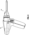
FIG. 2 is a side, perspective view of an adapter assembly secured to a powered actuation device for use with the stapler reload ofFIG. 1 ; -
FIG. 3 is a first side perspective view of the stapler reload shown inFIG. 2 ; -
FIG. 4 is a second side perspective view of the stapler reload shown inFIG. 2 ; -
FIG. 5 is an exploded perspective view of the stapler reload shown inFIG. 2 ; -
FIG. 6 is a cross-sectional view taken along section line 6-6 ofFIG. 3 ; -
FIG. 7 is an enlarged view of the indicated area of detail shown inFIG. 6 ; -
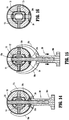
FIG. 8 is a cross-sectional view taken along section line 8-8 ofFIG. 7 ; -
FIG. 9 is a cross-sectional view taken along section line 9-9 ofFIG. 8 ; -
FIG. 10 is a perspective view of a large diameter portion of a body portion of the stapler reload ofFIG. 1 , with an upper half-section removed and a rotatable sleeve in a first or locked position; -
FIG. 11 is a cross-sectional view taken along section line 11-11 ofFIG. 7 ; -
FIG. 12 is a side perspective view of the large diameter portion shown inFIG. 10 with an outer tube removed and the rotatable sleeve in the first position; -
FIG. 13 is a side perspective view of the large diameter portion shown inFIG. 10 with the outer tube removed and the rotatable sleeve in a second or unlocked position; -
FIG. 14 is a cross-sectional view taken along section line 14-14 ofFIG. 7 , with a locking member in a proximal position and a shipping lock secured to the body portion of the stapler reload; -
FIG. 15 is a cross-sectional view taken along section line 15-15 shown inFIG. 7 , with the locking member in a distal position as the shipping lock is being released from the body portion of the stapler reload; -
FIG. 16 is a cross-sectional view taken along section line 16-16 shown inFIG. 7 , with the shipping lock removed; -
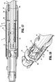
FIG. 17 is a cross-sectional view taken along section line 17-17 shown inFIG. 11 ; -
FIG. 18 is a perspective view of the large diameter portion shown inFIG. 10 , with the upper half-section removed and the rotatable sleeve in the second position; -
FIG. 19 is a perspective top view of the large diameter portion shown inFIG. 18 , with a lockout assembly in a first or unlocked condition; -
FIG. 20 is a cross-sectional view of the large diameter portion shown inFIG. 19 , subsequent to actuation of the stapler reload; -
FIG. 21 is a perspective top view of the large diameter portion shown inFIG. 19 , subsequent to actuation of the stapler reload; -
FIG. 22 is a perspective view of the large diameter portion shown inFIG. 21 , during a second actuation of the stapler reload; -
FIG. 23 is a perspective top view of a proximal portion of the large diameter portion shown inFIGS. 18-21 , with a lockout member and lockout member tool shown in phantom; -
FIG. 24 is a cross-sectional top view of the stapler reload shown inFIGS. 1 and2 ; -
FIG. 25 is a cross-sectional top view of the large diameter portion shown inFIGS. 18-21 , prior to actuation of the stapler reload; -
FIG. 26 is a cross-sectional top view of a small diameter portion of the stapler reload shown inFIGS. 1 and2 ; -
FIG. 27 is a perspective view of a proximal portion of an inner body of the small diameter portion shown inFIG. 26 ; -
FIG. 28 is a perspective view of the proximal portion of the inner body shown inFIG. 27 , with the outer tube removed; -
FIG. 29 is an enlarged perspective view of a pnuematic seal according to an embodiment of the present disclosure; -
FIG. 30 is a perspective view of an articulating portion of the presently disclosed stapler reload including a mounting assembly; -
FIG. 31 is a perspective view of a coupling member according to an embodiment of the present disclosure; -
FIG. 32 is a perspective view of the coupling member shown inFIG. 31 and an upper mounting bracket of the mounting assembly shown inFIG. 30 ; -
FIG. 33 is a perspective view of the coupling member and upper mounting bracket shown inFIG. 32 , prior to locking the coupling member to the upper mounting bracket; -
FIG. 34 is a perspective view of the coupling member and upper mounting bracket shown inFIGS. 32 and 33 , subsequent to locking the coupling member to the upper mounting bracket; -
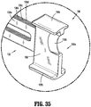
FIG. 35 is an enlarged section view of the indicated area of detail shown inFIG. 5 ; -
FIG. 36 is a perspective view of the articulating portion of the stapler reload shown inFIG. 30 with the upper mounting bracket of the mounting assembly and the cartridge assembly removed; -
FIG. 37 is a perspective view of the tool assembly the stapler reload shown inFIGS. 1 and2 ; -
FIG. 38 is a perspective, top view of the distal portion of the small diameter portion of the stapler reload shown inFIGS. 1 and2 , with the upper mounting bracket and upper housing half-section removed; -
FIG. 39 is a perspective, side view of the articulating portion of the stapler reload shown inFIG. 30 , with the outer tube of the body portion and the channel of the cartridge assembly removed; -
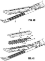
FIG. 40 is a perspective view of the tool assembly shown inFIG. 37 , with the channel of the cartridge assembly removed; -
FIG. 41 is a perspective view of the cartridge assembly shown inFIG. 40 , with parts separated; -
FIG. 42 is a perspective, top view of the body portion of the stapler reload shown inFIGS. 1 and2 , with the upper housing half-section and proximal tube body removed; -
FIG. 43 is a perspective view of the articulating portion of the stapler reload shown inFIG. 30 , with the outer tube of the small diameter portion removed; -
FIG. 44 is a perspective view of the assembled articulating portion of the stapler reload shown inFIG. 43 . -
FIG. 45 is a side perspective view of a stapler reload according to another embodiment of the present disclosure including a shipping lock; -
FIG. 46 is an enlarged side perspective view of a distal portion of the stapler reload and shipping lock shown inFIG. 45 ; -
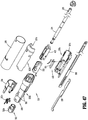
FIG. 47 is an exploded perspective view of a proximal portion of the stapler reload shown inFIG. 45 ; -
FIG. 48 is a cross-sectional view taken along section line 48-48 ofFIG. 45 ; -
FIG. 49 is a cross-sectional view taken along section line 49-49 ofFIG. 48 ; and -
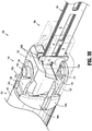
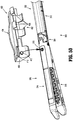
FIG. 50 is a side perspective view of the distal portion of the stapler reload and shipping lock shown inFIG. 46 . - Embodiments of the presently disclosed surgical stapler with a small diameter endoscopic portion will now be described in detail with reference to the drawings wherein like reference numerals designate identical or corresponding elements in each of the several views. In this description, the term "proximal" is used generally to refer to the portion of the apparatus that is closer to a clinician, while the term "distal" is used generally to refer to the portion of the stapler that is farther from the clinician. In addition, the term "endoscopic" is used generally to refer to surgical procedures performed through a small incision or a cannula inserted into a patient's body including endoscopic, laparoscopic and arthroscopic surgical procedures. Finally, the term clinician is used generally to refer to medical personnel including doctors, nurses, and support personnel.
-
FIG. 1 illustrates an embodiment of the presently disclosed small diameter reload is shown generally as stapler reload 100. The stapler reload 100 is part of asurgical stapling device 10 including a handle assembly oractuation device 20. In embodiments, the stapler reload 100 may be integrally formed with thehandle assembly 20. As shown, thehandle assembly 20 includes ahandle 22, atrigger member 24 pivotally secured to thehandle 22, and a pair of firing levers 26 (only one shown) extending from thehandle 22, and anelongated body 28 rotatably secured to thehandle 22 and including an articulatinglever 28a. For a detailed description of an exemplary handle assembly, please refer to commonly ownedU.S. Patent No. 8,070,033 , the content of which is incorporated herein by reference in its entirety. - Turning briefly to
FIG. 2 , it is envisioned that the stapler reload 100 may be operated with apowered handle assembly 20A. As shown, anadapter assembly 30A is secured to thepowered handle assembly 20A and the stapler reload 100 is secured to theadapter assembly 30A. It is envisioned that theadapter assembly 30A and the stapler reload 100 (FIG. 1 ) and/or thehandle assembly 20A can be integrally formed such that the stapler reload 100 is non-releasably supported on, or forms an integral extension of, theadapter assembly 30A and/or thehandle assembly 20A. For a detailed description of exemplary handle assemblies and adapter assemblies, please refer to commonly ownedU.S. Patent Application Publication No. 2012/0253329 ("the '329 publication"), the content of which is incorporated by reference herein in its entirety. - Referring to
FIGS. 3 and 4 , the stapler reload 100 includes abody portion 102, a mountingassembly 104, and atool assembly 106. Thebody portion 102 defines a longitudinal axis "x" that is aligned with the longitudinal axis of the adapter assembly 30 (FIG. 1 ) and has acoupling portion 108, alarge diameter portion 110, and an endoscopic orsmall diameter portion 112. Thelarge diameter portion 110 of the stapler reload 100 has a diameter greater than the diameter of thesmall diameter portion 112. In embodiments, thesmall diameter portion 112 of the stapler reload 100 is dimensioned to be received in an 8mm trocar assembly (not shown), whereas thelarge diameter portion 110 is about 12mm in diameter and dimensioned to support alock assembly 200 and alockout assembly 220, as discussed in detail below. - The
tool assembly 106 includes ananvil assembly 114 and acartridge assembly 116. In embodiments, thecartridge assembly 116 is pivotally supported in relation to theanvil assembly 114 and is movable between an open position (FIG. 2 ) and a closed or approximated position (FIG. 39 ). Alternately, theanvil 114 can be pivotally coupled to thecartridge assembly 116. The mountingassembly 104 is supported on a distal portion of thebody portion 102 and pivotally supports thetool assembly 106 to facilitate articulation of thetool assembly 106 about an axis perpendicular to the longitudinal axis "x" of thebody portion 102 between an articulated position in which a longitudinal axis of thetool assembly 106 defines an acute angle with the longitudinal axis "x" of thebody portion 102 and a non-articulated position in which the longitudinal axes of thetool assembly 106 and thebody portion 102 are aligned. - Referring to
FIG. 5 , thelarge diameter portion 110 of thebody portion 102 of the stapler reload 100 includes aninner housing 120 having an upper housing half-section 120a and a lower housing half-section 120b that are secured relative to each other with a tab and slot configuration as shown, or in any other suitable manner.. The upper and lower housing half-sections channels drive member 124 and afirst articulation link 126. The upper and lower housing half-sections proximal body tube 128 that prevents separation of thehalf sections - The proximal portion of the upper housing half-
section 120a defines thecoupling portion 108 and includesengagement nubs 130 for releasably engaging the distal portion of the adapter assembly 30 (FIG. 1 ) in a bayonet-type coupling arrangement. For a detailed description of an exemplary coupling portion please refer to commonly ownedU.S. Patent No. 5,865,361 ("the '361 patent"), the content of which is incorporated herein by reference in its entirety. - An
electrical connector assembly 122 is supported within the proximal portion of the upper housing half-section 120a of thebody portion 102 of the stapler reload 100. Theconnector assembly 122 includes aconnector base 122a and acontact member 122b. For a detailed discussion of an exemplary electrical connection assembly, please refer to commonly ownU.S. Pat. App. Pub. No. 2016/0249929 ("the '929 application"), the content of which is incorporated by reference herein in its entirety. - The
drive member 124 of the stapler reload 100 includes a proximal portion that supports adrive block 132. Thedrive block 132 is configured to releasably engage a control rod 32 (FIG. 2 ) of the adapter assembly 30 (FIG. 2 ) to translate movement of thecontrol rod 32 into movement of thedrive member 124. Thedrive block 132 is operably engaged by a lockingsleeve 134 to prevent firing of the stapler reload 100 prior to the stapler reload 100 being properly secured to adapter assembly 20 (FIG. 1 ). A distal portion of thedrive member 124 defines aslot 125 that engages a hooked proximal portion of adrive assembly 136 such that distal movement of thedrive member 124 effects distal movement of thedrive assembly 136. - By providing the stapler reload 100 with a
large diameter portion 110 for housing thedrive block 132 and the lockingsleeve 134, as well as other components of thestapler 10 described below, the diameter of thesmall diameter portion 112 can be minimized, for example, to about 8mm such that it may be received within an 8mm trocar assembly (not shown), while thelarge diameter portion 110 may be about 12 mm in diameter or larger. - Referring still to
FIG. 5 , thefirst articulation link 126 defines a hookedproximal portion 126a that is configured to engage an articulation shaft (not shown) of the adapter assembly 30 (FIG. 1 ) when the stapler reload 100 is secured to the adapter assembly 30. Adistal portion 126b of thefirst articulation link 126 engages aproximal portion 138a of asecond articulation link 138. Although shown having a hook and notch configuration and a corresponding slotted configuration, the respectivedistal portion 126b of thefirst articulation link 126 and theproximal portion 138a of thesecond articulation link 138 may be secured to one another in any suitable manner. - The
proximal portion 138a of thesecond articulation link 138 is slidably positioned within thelarge diameter portion 110 of thebody portion 102 of the stapler reload 100. The distal portion 138b of thesecond articulation link 138 engages afirst articulation member 140a which is pivotally connected to alower mounting bracket 142 of the mountingassembly 104 at a location offset from the longitudinal axis of thebody portion 102 such that longitudinal movement of thesecond articulation link 138 effects pivotal movement of thetool assembly 106 about the longitudinal axis. - The
small diameter portion 112 of thebody portion 102 of the stapler reload 100 includes aninner body 144 having upper and lower half-sections outer tube 146. The upper and lower half-sections first channel 143a that slideably receives thedrive member 124 and thedrive assembly 136. The upper and lower half-sections second channel 143b that slideably receives thesecond articulation link 138. Respective distal ends of the upper and lower half-sections cutouts outer tube 146 includes aproximal flange 146a for securing theouter tube 146 to the upper and lower housing half-section large diameter portion 110 of thebody portion 102. Theouter tube 146 definesopenings 147a, 147b (FIG. 20 ) for receivingrespective protrusions FIG. 20 ) of respective upper and lower housing half-sections - As noted above, the
tool assembly 106 includes theanvil assembly 114 and thecartridge assembly 116. Theanvil assembly 114 includes ananvil body 150 and ananvil cover 152 which is secured to the topside of theanvil body 150 to define a channel (not shown). In embodiments, staple pockets 151 are formed directly into theanvil body 150. Alternatively, theanvil body 150 may be provided with an anvil plate (not shown). In embodiments, theanvil body 150 may be one-piece, e.g., monolithic. In embodiments, the staple pockets may be formed using micro-electrolytic dissolution (MED). In embodiments, theanvil body 150 may include a lubricated hard coating. - In embodiments, a
dissector tip 154 is supported on the distal portion of theanvil body 150. Theanvil body 150 defines plurality of staple receiving depressions 151 (FIG. 37 ) and a longitudinal slot 153 which is dimensioned to slideably receive a portion of a workingportion 156 of thedrive assembly 136 of the stapler reload 100. A proximal portion of theanvil body 150 includes abracket 150a defining ahole 157 for receiving a pivot member orboss 162a of anupper mounting bracket 162 of the mountingassembly 104. - In embodiments, the
tissue dissector 154 is secured to a distal portion of theanvil assembly 114 with friction fit, adhesives, welding, mechanical fasteners, or in any suitable manner. Thetissue dissector 154 has a tapered configuration and extends distally of the distal portion of thecartridge assembly 116 to allow thetool assembly 106 to be manipulated about tissue adjacent a surgical site. Thetissue dissector 154 may be attached to the distal portion of theanvil assembly 114, as shown, or may be integrally and/or monolithically formed with theanvil assembly 114. Alternately, thetissue dissector 154 may be attached to thecartridge assembly 116. In addition, theanvil assembly 114 may include a buttress material (not shown) to strengthen tissue being sutured and dissected as is known in the art. - In some embodiments, the
cartridge assembly 116 includes achannel 164 and a staple cartridge 166 that is received within thechannel 164. It is envisioned that the staple cartridge 166 may be attachable to thechannel 164 by a snap-fit connection, or in any suitable manner, and may be removable to permit replacement following a stapling procedure. For a detailed description of an exemplary replaceable staple cartridge assembly, please refer commonly ownedU.S. Pat. App. Pub. No. 2012/0286021 ("the '021 publication"), the content of which is incorporated herein by reference in its entirety. - The
channel 164 is pivotally secured to theanvil body 150 bypivot pins 168 which extend throughopenings 151a formed in theanvil body 150 andopenings 151b formed in thechannel 164. The staple cartridge 166 includes acartridge body 170 which may define only two rows ofstaple retention slots 171a on each side of aknife slot 171b to facilitate reduction in the diameter of thetool assembly 106. Theknife slot 171b is aligned with anelongated slot 165 defined in thechannel 164 to facilitate passage of adynamic clamping member 156a. Thestaple retention slots 171a are positioned along a tissue contact surface of thecartridge body 170 and are aligned with the staple forming depressions 151 (FIG. 37 ) of theanvil body 150. Eachstaple retention slot 171a is configured to receive a fastener or staple "S" and apusher 174. Acartridge shield 172 allows thepushers 174 to float, and prevents thepushers 174 from exiting a respectivestaple retention slot 171a during transport and prior to use. Anactuation sled 176 is positioned to pass longitudinally through thecartridge body 170 into engagement with thepushers 174 to sequentially eject the staples "S" from thecartridge body 170. For a detailed description of an exemplary cartridge assembly, please refer to commonly ownedU.S. Pat. App. Pub. No. 2013/0098965 ("the '965 publication"), the content of which is incorporated by reference herein in its entirety. - The mounting
assembly 104 includes theupper mounting bracket 162 and the lower mountingmember 142. Each of the upper and lower mountingbrackets boss FIG. 33 ), respectively. As discussed above, thepivot member 162a is received within thehole 157 of thebracket 150a of theanvil body 150 to secure theupper mounting bracket 162 to theanvil body 150. Afirst coupling member 178 has a first portion which defines anopening 179 that also receives thepivot member 162a and a second portion which is received within thecutout 145a defined in the distal portion of the upper half-section 144a of thesmall diameter portion 112 of thebody portion 102 of the stapler reload 100. Thepivot member 142a on thelower mounting bracket 142 is received in anopening 181 defined in a first portion of asecond coupling member 180. Thesecond coupling member 180 has a second portion that is received within thecutout 145b defined within lower housing half-section 144b of thebody portion 102 to pivotally secure thelower mounting bracket 142 to the lower housing half-section 144b of the inner body 140 of thebody portion 102 of the stapler reload 100. - The pivot pins 168 extend through
openings 151a formed in theanvil body 150 andopenings 151b formed in thechannel 164, and are received inopenings 141 formed inlower mounting bracket 142 to secure thelower mounting bracket 142 to thechannel 164. The upper and lower mountingbrackets pin members - Referring to
FIGS. 5-13 , alock assembly 200 is supported on the proximal portion oflarge diameter portion 110 of thebody portion 102 of the stapler reload 100 to prevent axial movement of thedrive assembly 136 until the stapler reload 100 is properly attached to the adapter assembly 30 (FIG. 1 ) of the surgical stapler 10 (FIG. 1 ). Thelock assembly 200 includes thedrive block 132 supported on the proximal portion of thedrive member 124 and therotatable sleeve 134 is configured for selective engagement with thedrive block 132 to prevent longitudinal movement of thedrive member 124. Therotatable sleeve 134 is mounted about the proximal portion of thehousing 120 of thebody portion 102, and includes two proximally extendingfingers 202a. Therotatable sleeve 134 also includes adistally extending flange 202b. Alock plate 204 is slideably supported within a cutout 201a of the lower housing half-section 120b of theinner housing 120 of thebody portion 102 of the stapler reload 100, and is positioned to be engaged by thedistally extending flange 202b of therotatable sleeve 134 during attachment of the stapler reload 100 to the adapter assembly 30 (FIG. 1 ) to prevent forward movement of thedrive member 124. - The
rotatable sleeve 134 also includes a blockingfinger 202c that extends downwardly into the path of thedrive block 132 to obstruct movement of thedrive block 132 when therotatable sleeve 134 is in a first or locked position. When therotatable sleeve 134 is rotated, as indicated by arrow "A" inFIGS. 11 and13 , the blockingfinger 202c is moved from the first position (FIG. 8 ) in engagement with thedrive block 132 to a second position (FIG. 11 ) spaced from thedrive block 132 to facilitate longitudinal movement of thedrive block 132 and, thus,drive member 124. - With particular reference to
FIG. 7 , when therotatable sleeve 134 is positioned about the proximal portion of the lower housing half-section 120b, theproximally extending fingers 202a of the lockingsleeve 134 are positioned in alignment with thenubs 130 on the upper housing half-section 120a. Each proximally extendingfinger 202a includes an inwardly extendingprotrusion 203 that is received in arespective recess 205 formed on an outer surface of theupper half section 120a to releasably retain thesleeve 134 in the first position. When the stapler reload 100 is attached to an adapter assembly 30 (FIG. 1 ), the proximal portion of the stapler reload 100 is inserted into the distal portion of the adapter assembly 30 (FIG. 1 ) and rotated to engage the bayonet-type coupling components of the stapler reload 100 and the adapter assembly 30. As the adapter assembly 30 is rotated in relation to the stapler reload 100, a portion of the adapter assembly 30 engages theproximally extending fingers 202a of therotatable sleeve 134 to rotate therotatable sleeve 134 about theinner housing 120 of the stapler reload 100 from the first position (FIG. 8 ) to the second position (FIG. 11 ). - The stapler reload 100 is provided with a
shipping lock 208 configured to prevent operation of the stapler reload 100. Theshipping lock 208 is selectively secured to thelarge diameter portion 110 of thebody portion 102 of the stapler reload 100 and extends through anopening 123c in thedrive member 124 to prevent axial movement of thedrive member 124. Theshipping lock 208 is configured to be separated from thebody portion 102 of the stapler reload 100 only after the stapler reload 100 is properly secured to an actuation device 20 (FIG. 1 ). - As noted above, rotation of the
rotatable sleeve 134 from the first position to the second position also causes thedistally extending flange 202b of therotatable sleeve 134 to engage thelock plate 204. With particular reference toFIGS. 12 and 13 , thelock plate 204 is received within thecutout 201 of the lower housing half-section 120b and is configured to prevent release of the shipping lock 208 (FIG. 7 ) from engagement with thebody portion 102 of the staple reload 100 until the staple reload 100 is properly secured to the adapter assembly 30 (FIG. 1 ). More particularly, thelock plate 204 is biased proximally by aspring 210 and defines alock slot 205 for releasably engaging alocking pin 212 of theshipping lock 208. Thelock slot 205 includes asmall diameter portion 205a sized to be received around a notchedportion 212a (FIG. 7 ) of thelocking pin 212 of theshipping lock 208, and alarge diameter portion 205b through which the entirety of thelocking pin 212 can be received. - During rotation of the
rotatable sleeve 132, the distally extending flange 206 of therotatable sleeve 134 engages acammed surface 204a of thelock plate 204, causing thelock plate 204 to move in the distal direction, as indicated by arrows "B" inFIG. 13 , against the bias of thespring 210. As thelock plate 204 moves from a proximal position (FIG. 12 ) to a distal position (FIG. 13 ), thelock slot 205 is moved from having thesmall diameter portion 205a positioned about the notchedportion 212a of thelocking pin 212 to having thelarge diameter portion 205b received about thelocking pin 212. With the notchedportion 212a of thelocking pin 212 positioned within thelarge diameter portion 205b, the lockingpin 212 can be withdrawn from the stapler reload 100. In this manner, distal movement of thelock plate 204 permits release of thelocking pin 212 of theshipping lock 208 from engagement with the stapler reload 100. - Turning now to
FIG. 14 , theshipping lock 208 is shown secured to thelarge diameter portion 110 of thebody portion 102 of the stapler reload 100. In particular,curved arms 208a of theshipping lock 208 are received aboutproximal body tube 128 of thelarge diameter portion 110 of thebody portion 102 and thelocking pin 212 is received through openings in the upper and lower housing half-sections housing 120, and through openings in alockout shield 222 and thedrive member 124. In this manner, thedrive member 124 is prevented from longitudinal movement in any direction. The notchedportion 212a of thelocking pin 212 is engaged by thelock plate 204 to prevent theshipping lock 208 from accidentally disengaging from the stapler reload 100 prior to the staple reload 100 being properly secured to the adapter assembly 30 (FIG. 1 ). - With reference now to
FIG. 15 , during rotation of therotatable sleeve 134 during attachment of the stapler reload 100 to the adapter assembly 30 (FIG. 1 ), thelock plate 204 is moved distally via engagement with theflange 202b of rotatable sleeve 134 (FIG. 13 ) to align thelarge portion 205b of thelock slot 205 with thelocking pin 212 of theshipping lock 208. In this manner, the lockingplate 204 is disengaged from within thelocking pin 212 such that thelocking pin 212 is no longer secured to thebody portion 102 of the stapler reload 100, and theshipping lock 208 is free to be separated from thebody portion 102 of the stapler reload 100. Ahandle portion 208b of theshipping lock 208 is configured to be grasped and facilitate separation of theshipping lock 208 from thebody portion 102. More particularly, thehandle portion 208b permits a user to pull theshipping lock 208 radially outward from thebody portion 102 of the stapler reload 100 to overcome the spring force of thearms 208a of theshipping lock 208 to release theshipping lock 208 from thebody portion 102 of the stapler reload. - Turning briefly to
FIG. 16 , once the shipping lock 208 (FIG. 15 ) is separated from the stapler reload 100, the stapler reload 100 is ready for use. - With reference now to
FIGS. 5 and18-23 , thelarge diameter portion 110 of thebody portion 102 of the stapler reload 100 includes alockout assembly 220 to prevent subsequent advancement of thedrive member 124 following firing of the stapler reload 100. Thelockout assembly 220 includes alockout shield 222 and alockout member 224. Thelockout shield 222 is slideably disposed about a proximal portion of thedrive member 124 and includes a pair of proximally extending and outwardly biased shield lances 226a (FIGS. 19 and 20 ) and a pair of distally extendingshield fingers 226b. The shield lances 226a operate to prevent retraction of thelockout shield 222 subsequent to actuation of the stapler reload 100. Theshield fingers 226b engage a proximal set ofnotches 123a (FIG. 5 ) of thedrive member 124 prior to actuation of the stapler reload 100, i.e., before thelockout shield 222 is moved distally (FIG. 17 ), to maintain thelockout shield 222 in engagement with thedrive block 132. Subsequent to advancement of thedrive block 132 and the lockout shield 222 (FIG. 21 ), theshield fingers 226b engage a distal set ofnotches 123b (FIG. 5 ) in the drive member 124 (FIG. 17 ) to assist in retaining thedrive member 124 subsequent to retraction of thedrive member 134. - With particular reference to
FIGS. 19 and21 , thelockout member 224 is pivotally supported within theinner housing 120 of thebody portion 102 and includes aproximal portion 224a that is biased radially inward by a spring member, e.g.,leaf spring 225, into engagement with thelockout shield 222 prior to firing of the stapler reload 100 (FIG. 26 ) and into engagement with thedrive member 124 subsequent to retraction of thedrive member 124 following actuation of the stapler reload 100. - With particular reference to
FIG. 20 , during actuation of the stapler reload 100, engagement of thedrive block 132 by the connector rod 32 (FIG. 2 ) of the adapter assembly 30 (FIG. 2 ) causes thedrive member 124 and thelockout shield 222 to advance distally, as indicated by arrows "C" inFIG. 20 . As thedrive block 132 is advanced, thelockout shield 222 is moved distally into theouter tube 146 of thesmall diameter portion 112 of thebody portion 102 of the stapler reload 100. Once thelockout shield 222 is received within theouter tube 146, the shield lances 226a of thelockout shield 222 engageprotrusions sections housing 120. Engagement of theshield lances 226a with theprotrusion sections lockout shield 222 as thedrive member 124 is retracted to its initial position subsequent to the actuation stroke. - With particular reference now to
FIG. 21 , when thedrive member 124 returns to its initial position, subsequent to the actuation stroke of the stapler reload 100, as noted above, thelockout shield 222 remains within theouter tube 146 of thesmall diameter portion 110 of thebody portion 102 of the stapler reload 100 because of the shield lances 226a of thelockout shield 222 prevent proximal movement of thelockout shield 222. Without thelockout shield 222 being received around the proximal portion of thedrive member 124, theproximal portion 224a of thelockout member 224 directly engages thedrive member 124. During any subsequent attempted actuations of the stapler reload 100 after the initial actuation, theproximal portion 224a of thelockout member 224 will engage aflange 232 located distal of the proximal portion of thedrive member 124, thereby preventing further distal movement of thedrive member 124. - As shown in
FIG. 23 , a lockout reset opening 229 is provided in thehousing 120 of thebody portion 102 of the stapler reload 100 to permit overriding of thelockout assembly 220. In particular, a tool, e.g.,screw driver 234, may be received through the lockout reset opening 229 and engaged with adistal portion 224b of thelockout member 224, as indicated by arrow "D", to pivot theproximal portion 224a of thelockout member 224 from engagement with the flange 232 (FIG. 22 ) of thedrive member 124, as indicated by arrow "E". - With reference briefly to
FIGS. 24-26 , as described above, thefirst articulation link 126 is releasably coupled to an articulation mechanism (not shown) of the adapter assembly 30 (FIG. 1 ) to control articulation of thetool assembly 106. More specifically, when the articulation mechanism of the adapter assembly 30 is operated, thefirst articulation link 126 is advanced (or retracted) to cause corresponding advancement (or retraction) of thesecond articulation link 138. The distal portion of thesecond articulation link 138 engages afirst articulation member 140a which is pivotally connected to thepin member 182a of thelower mounting bracket 142 of the mountingassembly 104. As shown inFIG. 26 , thepin member 182a is positioned at a location offset from the longitudinal axis of thebody portion 102 such that longitudinal movement of thefirst articulation member 140a effects pivotal movement of thetool assembly 106 about a perpendicular axis, as indicated by arrow "F" inFIG. 24 . - A
second articulation member 140b is positioned parallel to thefirst articulation member 140a and engages thepin member 182b of thelower mounting bracket 142 of the mountingassembly 104. Each of the first andsecond articulation members curved support surface plates 250 which extend between thebody portion 102 and thetool assembly 106 of the stapler reload 100. - With reference to
FIGS. 27-29 , the stapler reload 100 includes apnuematic seal 240 for creating a seal around thedrive member 124 and thesecond articulation link 138. Thepnuematic seal 240 includes acircular base portion 240a and aflange portion 240b extending from thebase portion 240a. Thebase portion 240a is configured to fluidly seal a proximal portion of theinner body 144 of thesmall diameter portion 112 of thebody portion 102 of the stapler reload 100. Theflange portion 240b engages a proximal portion of theinner body 144 of thesmall diameter portion 112 of thebody portion 102. Thepnuematic seal 240 defines acentral opening 241a for accommodating thedrive member 124 in a sealing manner. Thepnuematic seal 240 further defines anotch 241b for accommodating thesecond articulation link 138. Thepnuematic seal 240 is disposed within theinner body 144 of thesmall diameter portion 112 of thebody portion 102 and creates a seal between each of thedrive member 124 and thesecond articulation link 138 and theinner body 144. - With reference now to
FIGS. 30-34 , the mountingassembly 104 of the stapler reload 100 includes the upper and lower mountingbrackets second coupling members second coupling members opening pivot members brackets openings second coupling members notch FIG. 31 ) that receives thetab FIG. 30 ; shown in phantom) extending from therespective pivot members brackets second coupling members respective pivot members respective notches second coupling members respective tabs respective pivot members second coupling members FIG. 33 ), in which the first andsecond coupling members FIG. 34 ) in which the first andsecond coupling members second coupling members brackets assembly 104 creates a rivetless pivot assembly for articulating thetool assembly 106 of the stapler reload 100 relative to thebody portion 102. - As described above, each of the upper and
lower housing sections body portion 102 includecutouts FIG. 5 ). Each of the first andsecond coupling members portions cutouts portions second coupling members sections inner body 144 of thesmall diameter portion 112 of thebody portion 102 of the stapler reload 100. - Referring to
FIG. 35 , in embodiments, thedrive assembly 136 is formed from a plurality ofstacked sheets 136a-d of a resilient material, e.g., stainless steel, spring steel. The distal portion of each of thesheets 136a-d of material of thedrive assembly 136 is secured to thedynamic clamping member 156a such as by welding. The proximal ends ofsheets 136a-d are hook-shaped and are received in theslot 125 in the distal portion of thedrive member 124 such that longitudinal movement of thedrive member 124 effects longitudinal movement of thedrive assembly 136. - As best shown in
FIG. 35 , thedynamic clamping member 156a includes aknife 156b supported or formed on avertical strut 158 of thedynamic clamping member 156a. Thedynamic clamping member 156a includes anupper flange 158a and alower flange 158b. Theupper flange 158a is positioned to be slideably received within the cavity (not shown) of theanvil assembly 114 and thelower flange 158b is positioned to be slideably positioned along anouter surface 164a (FIG. 37 ) of thechannel 164 of thecartridge assembly 116. In embodiments, either or both of thedynamic clamping member 156a and thechannel 164 are lubricated with a hard coating. Distal movement of thedrive assembly 136 initially advances thelower flange 158b into engagement with acam surface 164b formed on thechannel 164 to pivot thecartridge assembly 116 towards theanvil assembly 114 to a closed or approximated position (FIG. 38 ). - Thereafter, advancement of the
drive assembly 136 progressively defines a maximum tissue gap between theanvil assembly 114 andcartridge assembly 116 adjacent thedynamic clamping member 156a as thedynamic clamping member 156a moves through thetool assembly 106. In embodiments, at least portions of thedynamic clamping member 156a and/orchannel 164 are formed from and/or coated with a friction reducing material to minimize the force required to fire thesurgical stapler 10 by facilitating substantially frictionless passage of thedynamic clamping member 156a through the stapler reload 100. For a detailed description of an exemplary drive assembly and dynamic clamping member, please refer to the '965 publication, the content of which was previously incorporated herein. - With reference to
FIG. 38 , a blow-out plate 250 is positioned on each side of thedrive assembly 136 to prevent buckling of thedrive assembly 136 during straight and articulated firing of the stapler reload 100. The blow-outplates 250 extportion between thebody portion 102 and thetool assembly 106 of the stapler reload 100. Adistal portion 250b of each of the blow-outplates 250 is fixedly secured to thelower mounting bracket 142 of the mountingassembly 104. In embodiments, thedistal portion 250a of each of the blow-outplates 250 is press fit within a slot (not shown) formed in the lower mounting bracket 142 (shown in phantom inFIG. 30 ) to axially fix thedistal portion 250b of each of the blow-outplates 250 to thelower mounting bracket 142. Each of the first andsecond articulation members curved portions plates 250. - When the
drive assembly 136 is advanced to advance thedynamic clamping member 156a through thecartridge body 170 to fire staples "S" with thetool assembly 106 in an articulated position, the blow-outplates 250 prevent thedrive assembly 136 from buckling outward. - Turning to
FIGS. 40 and 41 , thesled 176 is supported within thecartridge body 170 at a position immediately distal of thedynamic clamping member 156a. The distal portion of thedynamic clamping member 156a is positioned to engage and drive thesled 176 through thecartridge body 170 of thecartridge assembly 116. Thesled 176 includes first andsecond cam members pushers 174 positioned within thecartridge assembly 116 to eject the staples "S" from thecartridge body 170. Eachpusher 174 supports two staples "S" positioned on one side of theknife slot 171b of thecartridge body 170. As noted above, thecartridge assembly 116 includes thecartridge shield 172 for retaining thepushers 176 within thecartridge body 170. More particularly, thecartridge shield 172 allows thepushers 176 to be floating, and prevents thepushers 174 from exiting thestaple retention slots 171a during transport. - With reference now to
FIGS. 42-44 , thesurgical stapler 10 is configured to distribute actuation forces along a load path which enables the stapler reload 100 to have a smaller diameter. The load path begins with theknife 156b (FIG. 35 ) of thedynamic clamping member 156a (FIG. 35 ) of the drive assembly 136 (FIG. 35 ) cutting through tissue (not shown). More specifically, in the presently disclosedsurgical stapler 10, the load is transferred from thedynamic clamping member 156a to the anvil andcartridge assemblies dynamic clamping member 156a travels therethrough. The load is then transferred from the anvil andcartridge assemblies lower mounting bracket 142 by pivot pins 168. The first andsecond pivot members brackets assembly 104 transfer the load from the lower and upper mountingbrackets second coupling members second coupling members inner body 144 of thesmall diameter portion 112 of thebody portion 102 of the stapler reload 100. - With particular reference now to
FIG. 42 , theinner body 104 of thesmall diameter portion 112 of thebody portion 120 of the stapler reload 100 defines acutout 253 for receiving adinking plate 254. The dinkingplate 254 is positioned to engage adinking lance 256 located on theouter tube 146 of thesmall diameter portion 112 of thebody portion 102 of the stapler reload 100. The dinking plate andlance inner body 104 of thesmall diameter portion 112 of thebody portion 102 to theinner housing 120 of thelarge diameter portion 110 of the stapler reload 100. Theinner housing 120 transfers the load to the actuation device 20 (FIG. 1 ) via the adapter assembly 30 (FIG. 1 ). - With reference now to
FIGS. 45-50 , another embodiment of a small diameter reload is shown generally as stapler reload 300. The stapler reload 300 is substantially similar to the stapler reload 100 described hereinabove except that the configuration of the shipping lock is changed, the location of the shipping lock is moved from the large diameter portion of the body portion to the small diameter portion of the body portion, and the configuration of the body portion and the tool assembly is modified to accommodate the changes in configuration and location of the shipping lock. - Referring initially to
FIGS. 45 and 46 , the stapler reload 300 includes abody portion 302, a mountingassembly 304, and atool assembly 306. Thebody portion 302 defines a longitudinal axis "x" that is aligned with the longitudinal axis of the adapter assembly 30 (FIG. 1 ) and has acoupling portion 308, alarge diameter portion 310, and an endoscopic orsmall diameter portion 312. Thelarge diameter portion 310 of the stapler reload 300 has a diameter greater than the diameter of thesmall diameter portion 312. In embodiments, thesmall diameter portion 312 of the stapler reload 300 is dimensioned to be received in an 8mm trocar assembly (not shown), whereas thelarge diameter portion 310 is about 12mm in diameter. Alternately, other dimensions are envisioned. - The
tool assembly 306 includes ananvil assembly 314 and acartridge assembly 316. In embodiments, thecartridge assembly 316 is pivotally supported in relation to theanvil assembly 314 and is movable between an open position and a closed or approximated position. The mountingassembly 304 is supported on a distal portion of thesmall diameter portion 312 of thebody portion 302 and pivotally supports thetool assembly 306 to facilitate articulation of thetool assembly 306 about an axis perpendicular to the longitudinal axis "x" of thebody portion 302 between an articulated position in which a longitudinal axis of thetool assembly 306 defines an acute angle with the longitudinal axis "x" of thebody portion 302 and a non-articulated position in which the longitudinal axes of thetool assembly 306 and thebody portion 302 are aligned. - With particular reference now to
FIG. 47 , thelarge diameter portion 310 of thebody portion 302 of the stapler reload 300 includes aninner housing 320 having aproximal housing section 320a, an upper housing half-section 320b, and a lower housing half-section 320c. The upper and lower housing half-sections proximal housing section 320a. Alternately, the housing sections can be secured together in other suitable manners. Theproximal housing section 320a and the upper and lower housing half-sections channels drive member 324 and afirst articulation link 326. Theproximal housing section 320a and the upper and lower housing half-sections proximal body tube 328 that prevents separation of the upper and lower housing half-sections sections proximal housing section 320a. - The proximal portion of the upper housing half-
section 320a defines thecoupling portion 308 and includesengagement nubs 330 for releasably engaging the distal portion of the adapter assembly 30 (FIG. 1 ) in a bayonet-type coupling arrangement. For a detailed description of an exemplary coupling portion please refer to the '361 patent. - An
electrical connector assembly 322 is supported within the proximal portion of the upper housing half-section 320a of thebody portion 302 of the stapler reload 300. Theconnector assembly 322 includes aconnector base 322a and acontact member 322b supported on thebase 322a. For a detailed discussion of an exemplary electrical connection assembly, please refer to the '929 application. - The
drive member 324 of the stapler reload 300 includes a proximal portion that supports adrive block 332. Thedrive block 332 releasably engages a control rod 32 (FIG. 2 ) of the adapter assembly 30 (FIG. 2 ) to translate movement of thecontrol rod 32 into movement of thedrive member 324. Thedrive block 332 is operably engaged by arotatable sleeve 334 to prevent firing of the stapler reload 300 prior to the stapler reload 300 being properly secured to adapter assembly 20 (FIG. 1 ). Thedrive block 332 and therotatable sleeve 334 of the stapler reload 300 are substantially similar in structure and operation to thedrive block 132 androtatable sleeve 134 of the stapler reload 100 described hereinabove. Thefirst articulation link 326 and asecond articulation link 338 are also substantially similar in structure and operation to the first and second articulation links 126, 138 of the stapler reload 100 described hereinabove. - The
large diameter portion 310 of thebody portion 302 of the stapler reload 300 further includes alockout assembly 420 to prevent readvancement of thedrive member 324 following firing of the stapler reload 300. Thelockout assembly 420 includes alockout shield 422 and alockout member 424. Thelockout assembly 420 operates in a similar manner tolockout assembly 220 of the stapler reload 100 described hereinabove. - By providing the stapler reload 300 with the
large diameter portion 310 for housing thedrive block 332 and therotatable sleeve 334, as well as configuring thelarge diameter portion 310 to accommodate components of thestapler 10, the diameter of thesmall diameter portion 312 is minimized, for example, to about 8mm such that it may be received within an 8mm trocar assembly (not shown), while thelarge diameter portion 310 may be about 12 mm in diameter or larger. - Referring now to
FIGS. 48 and 49 , thesmall diameter portion 312 of thebody portion 302 of the stapler reload 300 includes aninner body 344 received within anouter tube 346. Theinner body 344 defines achannel 343 that slideably receives the drive member 324 (FIG. 47 ) and a drive assembly 336. A distal end of the drive assembly 336 includes adynamic clamping member 356. Thedynamic clamping member 356 includes aknife portion 356a and upper andlower flanges upper flange 358a is positioned to be slideably received within alongitudinal cavity 313 of theanvil assembly 314 and thelower flange 358b is positioned to be slideably positioned along anouter surface 316a of thecartridge assembly 316. As described in detail above with regard to the stapler reload 100, initial distal movement of the drive assembly 336 causes pivoting of thecartridge assembly 316 towards theanvil assembly 314 to a closed or approximated position and continued distal movement of the drive assembly 336 within thetool assembly 306 effects the stapling and cutting of tissue (not shown). - With additional reference to
FIG. 50 , the stapler reload 300 is provided with ashipping lock 400 configured to prevent operation of the stapler reload 300 when theshipping lock 400 is secured to the stapler reload 300. Theshipping lock 400 is releasably secured to thesmall diameter portion 312 of thebody portion 302 of the staple reload 300 and extends across the mountingassembly 304 and over a proximal portion of thetool assembly 306. Theshipping lock 400 is configured to prevent advancement of the drive assembly 336 of the staple reload 300 and to prevent articulation of thetool assembly 306 relative to thebody portion 302. - The
shipping lock 400 includes anengagement portion 402, ahandle portion 404, and a lockingportion 406. Theengagement portion 402 of theshipping lock 400 releasably secures theshipping lock 400 to thesmall diameter portion 312 of thebody portion 302 of the stapler reload 300. More particularly, theengagement portion 402 includes a plurality of resilient,curved arms 408 that operate together to releasably grasp thesmall diameter portion 312 of thebody portion 302. Although shown with two sets of opposedcurved arms 408, it is envisioned that theshipping lock 400 may include any number ofcurved arms 408. - The
handle portion 404 of theshipping lock 400 is configured to be grasped by a user and facilitate separation of theshipping lock 400 from thebody portion 302 of the stapler reload 300. More particularly, thehandle portion 404 of theshipping lock 400 permits the user to pull theshipping lock 400 radially outward from thebody portion 302 of the stapler reload 300 to overcome the resilient force of theengagement portion 402 of theshipping lock 400 to release theshipping lock 400 from thebody portion 302 of the stapler reload 300. - The locking
portion 406 of theshipping lock 400 includes a lockingflange 410 and a lockingprojection 412. The lockingflange 410 is received about a proximal portion of theanvil assembly 314 of thetool assembly 306 to prevent articulation of thetool assembly 306 relative to thebody portion 302. The lockingprojection 412 is configured to extend through anopening 315 in the proximal portion of theanvil assembly 314 into engagement with thedynamic clamping member 356 when theshipping lock 400 is secured to the stapler reload 300 to prevent advancement of the drive assembly 336. More particularly, the lockingprojection 412 of theshipping lock 400 engages theupper flange 358a of thedynamic clamping member 356 of the drive assembly 336 to prevent distal movement of the drive assembly 336. - Once the
shipping lock 400 is separated from the stapler reload 300, the stapler reload 300 may be used in as described above with reference to the stapler reload 100. - Persons skilled in the art will understand that the devices and methods specifically described herein and illustrated in the accompanying drawings are non-limiting exemplary embodiments. It is envisioned that the elements and features illustrated or described in connection with one exemplary embodiment may be combined with the elements and features of another without departing from the scope of the present disclosure. As well, one skilled in the art will appreciate further features and advantages of the disclosure based on the above-described embodiments. Accordingly, the disclosure is not to be limited by what has been particularly shown and described, except as indicated by the appended claims.
- The invention may be described by reference to the following numbered paragraphs:-
- 1. A surgical stapler comprising:
- an actuation device;
- a stapler reload releasably secured to the actuation device, the stapler reload including a body portion, a tool assembly, and a drive assembly movable within tool assembly, the body portion including a large diameter portion defining a first diameter and a small diameter portion defining a second diameter extending distally from the large diameter portion, the tool assembly being supported on a distal portion of the small diameter portion, wherein the small diameter portion is dimensioned to pass through an 8mm trocar; and
- a shipping lock releasably secured to the distal portion of the small diameter portion of the body portion and engagable with the drive assembly for preventing longitudinal movement of the drive assembly.
- 2. The surgical stapler according to
paragraph 1, wherein the shipping lock is configured to prevent articulation of the tool assembly relative to the body portion. - 3. The surgical stapler according to paragraph 2, wherein the shipping lock includes a locking portion that engages the tool assembly to prevent articulation of the tool assembly relative to the body portion.
- 4. The surgical stapler according to
paragraph 1, wherein the tool assembly includes an anvil assembly and a cartridge assembly supporting a plurality of staples and the drive assembly is movable through the tool assembly to eject the plurality of staples from the cartridge assembly. - 5. The surgical stapler according to
paragraph 1, wherein the drive assembly includes a clamping member and the shipping lock includes a projection, the projection engaging the clamping member when the shipping lock is secured to the body portion to obstruct advancement of the drive assembly. - 6. The surgical stapler according to paragraph 5, wherein the clamping member includes an upper flange, the projection of the shipping lock engaging the upper flange to prevent advancement of the drive assembly.
- 7. The surgical stapler according to
paragraph 1, wherein the shipping lock includes curved arms configured to frictionally engage the body portion of the stapler reload. - 8. A surgical stapler comprising:
- an elongate body;
- a tool assembly pivotally secured to the elongate body;
- a drive member movable within the tool assembly between retracted and advanced positions; and
- a shipping lock releasably secured to the elongate body, the shipping lock including a projection, wherein when the shipping lock is secured to the elongate body, the projection obstructs movement of the drive member to its advanced position.
- 9. The surgical stapler according to paragraph 8, wherein the shipping lock is configured to prevent the tool assembly from pivoting relative to the body portion.
- 10. The surgical stapler according to
paragraph 9, wherein the shipping lock includes a locking portion that engages the tool assembly to prevent pivoting of the tool assembly relative to the body portion. - 11. The surgical stapler according to paragraph 8, wherein the tool assembly includes an anvil assembly and a cartridge assembly supporting a plurality of staples and the drive assembly is movable through the tool assembly to eject the plurality of staples from the cartridge assembly.
- 12. The surgical stapler according to paragraph 8, wherein the drive assembly includes a clamping member, wherein the projection is positioned to obstruct movement of the clamping member towards the advanced position when the shipping lock is secured to the body portion.
- 13. The surgical stapler according to
paragraph 12, wherein the clamping member includes an upper flange, the projection of the shipping lock being positioned to engage the upper flange to obstruct movement of the drive member to the advanced position. - 14. The surgical stapler according to paragraph 8, wherein the shipping lock includes curved arms configured to frictionally engage the elongate body.
Claims (15)
- A stapler reload (300) comprising:a body portion (302), a tool assembly (306), and a mounting assembly (304); drive assembly (336) movable within tool assembly, the body portion (302) including a coupling portion (308), a large diameter portion (310) defining a first diameter and a small diameter portion (312) defining a second diameter extending distally from the large diameter portion, the tool assembly (306) being supported on a distal portion of the small diameter portion (312), wherein the small diameter portion is dimensioned to be received in an 8mm trocar; anda shipping lock (400) releasably secured to the distal portion of the small diameter portion (312) of the body portion (302) and extending across the mounting assembly (304) and over a proximal portion of the tool assembly (306), said shipping lock (400) configured to be engagable with the drive assembly (336) for preventing longitudinal movement of the drive assembly (336),said shipping lock (400) comprising an engagement portion (402), a handle portion (404),and a locking portion (406), the engagement portion (402) configured to releasably secure the shipping lock (400) to the small diameter portion (312) of the body portion (302) of the stapler reload (300), said engagement portion (402)comprising a plurality of resilient, curved arms (408) are configured to operate together to releasably grasp the small diameter portion (312) of the body portion (302).
- The stapler reload (300) according to claim 1, wherein the tool assembly (306) includes an anvil assembly (314) and a cartridge assembly (316) supporting a plurality of staples and the drive assembly (336) is movable through the tool assembly to eject the plurality of staples from the cartridge assembly (316).
- The stapler reload (300) according to claim 2, wherein the distal end of the drive assembly (336) comprises a dynamic clamping member (356), said dynamic clamping member (356) comprising a knife portion (356a) and upper and lower flanges (358a, 358b), the upper flange (358a) configured to be positioned to be slideably received within a longitudinal cavity (313) of the anvil assembly (314) and the lower flange (358b) configured to be is positioned to be slideably positioned along an outer surface (316a) of the cartridge assembly (316).
- The stapler reload (300) according to any preceding claim, wherein the handle portion (404) of the shipping lock (400) is configured to be grasped by a user and facilitate separation of the shipping lock (400) from the body portion (302) of the stapler
- The stapler reload (300) according to claim 2 or any claim dependent thereon, wherein the locking portion (406) of the shipping lock 400 comprises a locking flange (410) and a locking projection (412), said locking flange (410) configured to be received about a proximal portion of the anvil assembly (314) of the tool assembly (306) to prevent articulation of the tool assembly (306) relative to the body portion (302).
- The stapler reload according to claim 5, wherein the locking projection (412) is configured to extend through an opening (315) in the proximal portion of the anvil assembly (314) into engagement with the dynamic clamping member (356) when the shipping lock (40) is secured to the stapler reload (300) to prevent advancement of the drive assembly (336).
- The stapler reload (300) according to any preceding claim, comprising at drive member (324), said drive member (324) comprising a proximal portion that supports a drive block (332), said drive block (332) configured to be releasably engageable with a control rod (32) of and adapter assembly (30) to translate movement of the control rod (32) into movement of the drive member (324).
- The stapler reload (300) according to claim 7, wherein the drive block (332) is operably engaged by a rotatable sleeve (334) to prevent firing of the stapler reload 300 prior to the stapler reload 300 being properly secured to the adapter assembly (30).
- The stapler reload (300) according to any preceding claim, wherein the mounting assembly (304) is supported on a distal portion of the small diameter portion (312) of the body portion (302) and pivotally supports the tool assembly (306).
- The stapler reload (300) according to claim 9, wherein the mounting assembly (304) is configured to facilitate articulation of the tool assembly (306) about an axis perpendicular to the longitudinal axis (x) of the body portion (302) between an articulated position in which a longitudinal axis of the tool assembly (306) defines an acute angle with the longitudinal axis (x) of the body portion (302) and a non-articulated position in which the longitudinal axes of the tool assembly (306) and the body portion (302) are aligned.
- The stapler reload (300) according to any preceding claim, wherein the large diameter portion (310) of the body portion (302) includes an inner housing (320) having a proximal housing section (320a), an upper housing half-section (320b), and a lower housing half-section (320c), wherein the proximal housing section (320a) and the upper and lower housing half-sections (320b, 320c) define channels (321a, 321b, 321c) which slidably receive a drive member (324) and a first articulation link (326), preferably wherein the proximal housing section (320a) and the upper and lower housing halfsections (320b, 320c) are received within a proximal body tube (328) that prevents separation of the upper and lower housing half-sections (320b, 320c) and, prevents separation of the upper and lower housing half-sections (320b, 320c) from the proximal housing section (320a).
- The stapler reload (300) according to claim 11, wherein the proximal portion of the upper housing half-section (320a) defines the coupling portion (308) and includes engagement nubs (330) for releasably engaging the distal portion of an
adapter assembly (30), preferably in a bayonet-type coupling arrangement. - The stapler reload (300) according to any preceding claim, further comprising an electrical connector assembly (322) supported within the proximal portion of the upper housing half-section (320a) of the body portion (302), said connector assembly (322) including a connector base (322a) and a contact member (322b) supported on the base (322a).
- The stapler reload (300) according to any preceding claim, wherein the large diameter portion (310) of the body portion (302) further includes a lockout assembly (420) configured to prevent readvancement of the drive member (324) following firing of the stapler reload (300), said lockout assembly (420) comprising a lockout shield (422) and a lockout member (424).
- A surgical stapler comprising:A handle assemblyanda stapler reload (300) according to any preceding claim.
Applications Claiming Priority (1)
| Application Number | Priority Date | Filing Date | Title |
|---|---|---|---|
| US16/297,055 US11350915B2 (en) | 2017-02-23 | 2019-03-08 | Surgical stapler with small diameter endoscopic portion |
Publications (1)
| Publication Number | Publication Date |
|---|---|
| EP3705055A1 true EP3705055A1 (en) | 2020-09-09 |
Family
ID=69780060
Family Applications (1)
| Application Number | Title | Priority Date | Filing Date |
|---|---|---|---|
| EP20161545.7A Withdrawn EP3705055A1 (en) | 2019-03-08 | 2020-03-06 | Surgical stapler with small diameter endoscopic portion |
Country Status (3)
| Country | Link |
|---|---|
| EP (1) | EP3705055A1 (en) |
| AU (1) | AU2020200469A1 (en) |
| CA (1) | CA3070632A1 (en) |
Cited By (2)
| Publication number | Priority date | Publication date | Assignee | Title |
|---|---|---|---|---|
| WO2022234429A1 (en) * | 2021-05-06 | 2022-11-10 | Covidien Lp | Surgical stapling device with optimized drive assembly |
| WO2023069563A1 (en) * | 2021-10-20 | 2023-04-27 | USB Medical, Ltd. | Improved surgical clamping instrument with emergency release |
Citations (9)
| Publication number | Priority date | Publication date | Assignee | Title |
|---|---|---|---|---|
| US5865361A (en) | 1997-09-23 | 1999-02-02 | United States Surgical Corporation | Surgical stapling apparatus |
| EP2499987A2 (en) * | 2011-03-18 | 2012-09-19 | Tyco Healthcare Group LP | Shipping wedge with lockout |
| US20120253329A1 (en) | 2007-09-21 | 2012-10-04 | Michael Zemlok | Hand held surgical handle assembly, surgical adapters for use between surgical handle assembly and surgical end effectors, and methods of use |
| US20120286021A1 (en) | 2011-05-12 | 2012-11-15 | Tyco Healthcare Group Lp | Replaceable staple cartridge |
| US20130098965A1 (en) | 2011-10-25 | 2013-04-25 | Stanislaw Kostrzewski | Multi-Use Loading Unit |
| US20160249929A1 (en) | 2015-02-26 | 2016-09-01 | Covidien Lp | Surgical apparatus |
| EP3064143A1 (en) * | 2015-03-04 | 2016-09-07 | Covidien LP | Surgical stapling loading unit having articulating jaws |
| EP3205291A1 (en) * | 2016-02-11 | 2017-08-16 | Covidien LP | Surgical stapler with small diameter endoscopic portion |
| EP3375386A2 (en) * | 2017-02-23 | 2018-09-19 | Covidien LP | Surgical stapler with small diameter endoscopic portion |
-
2020
- 2020-01-23 AU AU2020200469A patent/AU2020200469A1/en not_active Abandoned
- 2020-01-31 CA CA3070632A patent/CA3070632A1/en active Pending
- 2020-03-06 EP EP20161545.7A patent/EP3705055A1/en not_active Withdrawn
Patent Citations (10)
| Publication number | Priority date | Publication date | Assignee | Title |
|---|---|---|---|---|
| US5865361A (en) | 1997-09-23 | 1999-02-02 | United States Surgical Corporation | Surgical stapling apparatus |
| US8070033B2 (en) | 1997-09-23 | 2011-12-06 | Tyco Healthcare Group Lp | Surgical stapling apparatus |
| US20120253329A1 (en) | 2007-09-21 | 2012-10-04 | Michael Zemlok | Hand held surgical handle assembly, surgical adapters for use between surgical handle assembly and surgical end effectors, and methods of use |
| EP2499987A2 (en) * | 2011-03-18 | 2012-09-19 | Tyco Healthcare Group LP | Shipping wedge with lockout |
| US20120286021A1 (en) | 2011-05-12 | 2012-11-15 | Tyco Healthcare Group Lp | Replaceable staple cartridge |
| US20130098965A1 (en) | 2011-10-25 | 2013-04-25 | Stanislaw Kostrzewski | Multi-Use Loading Unit |
| US20160249929A1 (en) | 2015-02-26 | 2016-09-01 | Covidien Lp | Surgical apparatus |
| EP3064143A1 (en) * | 2015-03-04 | 2016-09-07 | Covidien LP | Surgical stapling loading unit having articulating jaws |
| EP3205291A1 (en) * | 2016-02-11 | 2017-08-16 | Covidien LP | Surgical stapler with small diameter endoscopic portion |
| EP3375386A2 (en) * | 2017-02-23 | 2018-09-19 | Covidien LP | Surgical stapler with small diameter endoscopic portion |
Cited By (3)
| Publication number | Priority date | Publication date | Assignee | Title |
|---|---|---|---|---|
| WO2022234429A1 (en) * | 2021-05-06 | 2022-11-10 | Covidien Lp | Surgical stapling device with optimized drive assembly |
| US11576670B2 (en) | 2021-05-06 | 2023-02-14 | Covidien Lp | Surgical stapling device with optimized drive assembly |
| WO2023069563A1 (en) * | 2021-10-20 | 2023-04-27 | USB Medical, Ltd. | Improved surgical clamping instrument with emergency release |
Also Published As
| Publication number | Publication date |
|---|---|
| CA3070632A1 (en) | 2020-09-08 |
| AU2020200469A1 (en) | 2020-09-24 |
Similar Documents
| Publication | Publication Date | Title |
|---|---|---|
| EP3375386B1 (en) | Surgical stapler with small diameter endoscopic portion | |
| US11457920B2 (en) | Surgical stapler with small diameter endoscopic portion | |
| US12064106B2 (en) | Devices and methods for facilitating ejection of surgical fasteners from cartridges | |
| CN110520063B (en) | Surgical stapler with insertable distal anvil end | |
| EP3858259B1 (en) | Stapling device with selective cutting | |
| US20050184124A1 (en) | Surgical stapling apparatus with locking mechanism | |
| BR112013022045B1 (en) | SURGICAL STAPLER | |
| US11350915B2 (en) | Surgical stapler with small diameter endoscopic portion | |
| CA3070632A1 (en) | Surgical stapler with small diameter endoscopic portion | |
| EP1813197A2 (en) | Surgical stapling apparatus with locking mechanism | |
| US11801054B2 (en) | Surgical stapler with oval tool assembly | |
| JP2008188433A (en) | Surgical stapling apparatus with locking mechanism |
Legal Events
| Date | Code | Title | Description |
|---|---|---|---|
| PUAI | Public reference made under article 153(3) epc to a published international application that has entered the european phase |
Free format text: ORIGINAL CODE: 0009012 |
|
| STAA | Information on the status of an ep patent application or granted ep patent |
Free format text: STATUS: THE APPLICATION HAS BEEN PUBLISHED |
|
| AK | Designated contracting states |
Kind code of ref document: A1 Designated state(s): AL AT BE BG CH CY CZ DE DK EE ES FI FR GB GR HR HU IE IS IT LI LT LU LV MC MK MT NL NO PL PT RO RS SE SI SK SM TR |
|
| AX | Request for extension of the european patent |
Extension state: BA ME |
|
| STAA | Information on the status of an ep patent application or granted ep patent |
Free format text: STATUS: THE APPLICATION IS DEEMED TO BE WITHDRAWN |
|
| 18D | Application deemed to be withdrawn |
Effective date: 20210310 |