EP3705024A1 - Inspection assistance device, endoscope device, inspection assistance method, and inspection assistance program - Google Patents
Inspection assistance device, endoscope device, inspection assistance method, and inspection assistance program Download PDFInfo
- Publication number
- EP3705024A1 EP3705024A1 EP18873241.6A EP18873241A EP3705024A1 EP 3705024 A1 EP3705024 A1 EP 3705024A1 EP 18873241 A EP18873241 A EP 18873241A EP 3705024 A1 EP3705024 A1 EP 3705024A1
- Authority
- EP
- European Patent Office
- Prior art keywords
- processing
- captured image
- image data
- visual
- lesion site
- Prior art date
- Legal status (The legal status is an assumption and is not a legal conclusion. Google has not performed a legal analysis and makes no representation as to the accuracy of the status listed.)
- Granted
Links
Images





Classifications
-
- A—HUMAN NECESSITIES
- A61—MEDICAL OR VETERINARY SCIENCE; HYGIENE
- A61B—DIAGNOSIS; SURGERY; IDENTIFICATION
- A61B1/00—Instruments for performing medical examinations of the interior of cavities or tubes of the body by visual or photographical inspection, e.g. endoscopes; Illuminating arrangements therefor
- A61B1/00002—Operational features of endoscopes
- A61B1/00043—Operational features of endoscopes provided with output arrangements
- A61B1/00045—Display arrangement
- A61B1/0005—Display arrangement combining images e.g. side-by-side, superimposed or tiled
-
- A—HUMAN NECESSITIES
- A61—MEDICAL OR VETERINARY SCIENCE; HYGIENE
- A61B—DIAGNOSIS; SURGERY; IDENTIFICATION
- A61B1/00—Instruments for performing medical examinations of the interior of cavities or tubes of the body by visual or photographical inspection, e.g. endoscopes; Illuminating arrangements therefor
- A61B1/00002—Operational features of endoscopes
- A61B1/00004—Operational features of endoscopes characterised by electronic signal processing
- A61B1/00009—Operational features of endoscopes characterised by electronic signal processing of image signals during a use of endoscope
- A61B1/000094—Operational features of endoscopes characterised by electronic signal processing of image signals during a use of endoscope extracting biological structures
-
- A—HUMAN NECESSITIES
- A61—MEDICAL OR VETERINARY SCIENCE; HYGIENE
- A61B—DIAGNOSIS; SURGERY; IDENTIFICATION
- A61B1/00—Instruments for performing medical examinations of the interior of cavities or tubes of the body by visual or photographical inspection, e.g. endoscopes; Illuminating arrangements therefor
- A61B1/00002—Operational features of endoscopes
- A61B1/00039—Operational features of endoscopes provided with input arrangements for the user
- A61B1/00042—Operational features of endoscopes provided with input arrangements for the user for mechanical operation
-
- A—HUMAN NECESSITIES
- A61—MEDICAL OR VETERINARY SCIENCE; HYGIENE
- A61B—DIAGNOSIS; SURGERY; IDENTIFICATION
- A61B1/00—Instruments for performing medical examinations of the interior of cavities or tubes of the body by visual or photographical inspection, e.g. endoscopes; Illuminating arrangements therefor
- A61B1/00002—Operational features of endoscopes
- A61B1/00043—Operational features of endoscopes provided with output arrangements
- A61B1/00045—Display arrangement
-
- A—HUMAN NECESSITIES
- A61—MEDICAL OR VETERINARY SCIENCE; HYGIENE
- A61B—DIAGNOSIS; SURGERY; IDENTIFICATION
- A61B1/00—Instruments for performing medical examinations of the interior of cavities or tubes of the body by visual or photographical inspection, e.g. endoscopes; Illuminating arrangements therefor
- A61B1/04—Instruments for performing medical examinations of the interior of cavities or tubes of the body by visual or photographical inspection, e.g. endoscopes; Illuminating arrangements therefor combined with photographic or television appliances
- A61B1/045—Control thereof
-
- G—PHYSICS
- G02—OPTICS
- G02B—OPTICAL ELEMENTS, SYSTEMS OR APPARATUS
- G02B23/00—Telescopes, e.g. binoculars; Periscopes; Instruments for viewing the inside of hollow bodies; Viewfinders; Optical aiming or sighting devices
- G02B23/24—Instruments or systems for viewing the inside of hollow bodies, e.g. fibrescopes
-
- G—PHYSICS
- G06—COMPUTING OR CALCULATING; COUNTING
- G06T—IMAGE DATA PROCESSING OR GENERATION, IN GENERAL
- G06T7/00—Image analysis
- G06T7/0002—Inspection of images, e.g. flaw detection
- G06T7/0012—Biomedical image inspection
-
- G—PHYSICS
- G06—COMPUTING OR CALCULATING; COUNTING
- G06V—IMAGE OR VIDEO RECOGNITION OR UNDERSTANDING
- G06V10/00—Arrangements for image or video recognition or understanding
- G06V10/20—Image preprocessing
- G06V10/22—Image preprocessing by selection of a specific region containing or referencing a pattern; Locating or processing of specific regions to guide the detection or recognition
-
- H—ELECTRICITY
- H04—ELECTRIC COMMUNICATION TECHNIQUE
- H04N—PICTORIAL COMMUNICATION, e.g. TELEVISION
- H04N7/00—Television systems
- H04N7/18—Closed-circuit television [CCTV] systems, i.e. systems in which the video signal is not broadcast
- H04N7/183—Closed-circuit television [CCTV] systems, i.e. systems in which the video signal is not broadcast for receiving images from a single remote source
-
- G—PHYSICS
- G06—COMPUTING OR CALCULATING; COUNTING
- G06T—IMAGE DATA PROCESSING OR GENERATION, IN GENERAL
- G06T2207/00—Indexing scheme for image analysis or image enhancement
- G06T2207/10—Image acquisition modality
- G06T2207/10068—Endoscopic image
-
- G—PHYSICS
- G06—COMPUTING OR CALCULATING; COUNTING
- G06T—IMAGE DATA PROCESSING OR GENERATION, IN GENERAL
- G06T2207/00—Indexing scheme for image analysis or image enhancement
- G06T2207/30—Subject of image; Context of image processing
- G06T2207/30004—Biomedical image processing
- G06T2207/30096—Tumor; Lesion
-
- G—PHYSICS
- G06—COMPUTING OR CALCULATING; COUNTING
- G06V—IMAGE OR VIDEO RECOGNITION OR UNDERSTANDING
- G06V2201/00—Indexing scheme relating to image or video recognition or understanding
- G06V2201/03—Recognition of patterns in medical or anatomical images
Definitions
- Step S3c the processing unit 44C makes the content of the recognition processing (at least one of the configuration or the parameters of the image recognition model) different between the attention region and the non-attention region of the captured image data.
- Fig. 12 The flowchart illustrated in Fig. 12 is the same as that in Fig. 7 except that Step S3b is changed to Step S32 and Step S4a is changed to Step S42.
- Step S3b is changed to Step S32
- Step S4a is changed to Step S42.
- Fig. 12 the same processing as that in Fig. 7 is denoted by the same reference numerals, and the description thereof will be omitted.
Landscapes
- Health & Medical Sciences (AREA)
- Engineering & Computer Science (AREA)
- Life Sciences & Earth Sciences (AREA)
- Surgery (AREA)
- Physics & Mathematics (AREA)
- Nuclear Medicine, Radiotherapy & Molecular Imaging (AREA)
- General Health & Medical Sciences (AREA)
- Medical Informatics (AREA)
- Radiology & Medical Imaging (AREA)
- Optics & Photonics (AREA)
- Animal Behavior & Ethology (AREA)
- Molecular Biology (AREA)
- Biophysics (AREA)
- Pathology (AREA)
- Biomedical Technology (AREA)
- Heart & Thoracic Surgery (AREA)
- Veterinary Medicine (AREA)
- Public Health (AREA)
- General Physics & Mathematics (AREA)
- Theoretical Computer Science (AREA)
- Multimedia (AREA)
- Signal Processing (AREA)
- Computer Vision & Pattern Recognition (AREA)
- Quality & Reliability (AREA)
- Mechanical Engineering (AREA)
- Astronomy & Astrophysics (AREA)
- Endoscopes (AREA)
Abstract
Description
- The present invention relates to an inspection support device, an endoscope device, an inspection support method, and an inspection support program.
- With the development of medical devices such as computed tomography (CT), magnetic resonance imaging (MRI), a virtual slide scanner for capturing a pathological specimen, or an endoscope device, a large amount of digitalized high-definition medical images can be acquired.
- In recent years, picture archiving and communication systems (PACS) for saving medical images have spread, and these images are sequentially stored together with the doctor's diagnostic findings. As such digitization of the medical images and accumulation of cases progress, it has become possible to detect or identify a lesion using a computer as described in, for example,
JP2014-094157A JP2005-034211A JP2001-258820A -
JP2014-094157A -
JP2005-034211A -
JP2001-258820A - In inspection using an endoscope device among the above-described medical devices, it is necessary to determine the presence or absence of a lesion site and to resect the lesion site while checking the captured image displayed on the display device in a state where an insertion part of the endoscope inserted into the body of a subject. For this reason, in the inspection using the endoscope device, it is necessary to perform the processing of detecting or identifying a lesion using a computer in real time during the inspection.
- Such real-time processing imposes a heavy processing load on the computer.
JP2014-094157A JP2005-034211A -
JP2001-258820A - It is necessary to operate the endoscope using both hands, and at the time of the inspection, the operator is in a state where both hands closed. For this reason, in the captured image displayed in real time, how to determine a region where the processing of detection or identification of a lesion by the computer is needed is important in securing the accuracy and efficiency of the inspection.
- The invention has been made in view of the above circumstances, and an object thereof is to provide an inspection support device, an endoscope device, an inspection support method, and an inspection support program that can make both the accuracy and efficiency of the inspection using the endoscope compatible.
- An inspection support device of the invention comprises a captured image data acquisition unit that acquires captured image data obtained by imaging the inside of a subject with an endoscope; a visual-line detection unit that detects a visual line directed to a display device that displays a captured image based on the captured image data; a processing unit that performs processing for performing at least detection of the detection of a lesion site from the captured image data and identification of the detected lesion site on the captured image data; and a display control unit that causes the display device to display a result of the processing by the processing unit, wherein the processing unit controls a content of the processing on the captured image data on the basis of the visual line detected by the visual-line detection unit.
- An endoscope device of the invention comprises the above inspection support device; and the endoscope.
- An inspection support method of the invention comprises a captured image data acquisition step of acquiring captured image data obtained by imaging the inside of a subject with an endoscope; a visual-line detection step of detecting a visual line directed to a display device that displays a captured image based on the captured image data; a processing step of performing processing for performing at least a detection of a lesion site from the captured image data out of the detection of the lesion site and identification of the detected lesion site on the captured image data; and a display control step of causing the display device to display a result of the processing by the processing step, wherein in the processing step, a content of the processing on the captured image data is controlled on the basis of the visual line detected by the visual-line detection step.
- An inspection support program of the invention causes a computer to execute a captured image data acquisition step of acquiring captured image data obtained by imaging the inside of a subject with an endoscope; a visual-line detection step of detecting a visual line directed to a display device that displays a captured image based on the captured image data; a processing step of performing processing for performing at least a detection of a lesion site from the captured image data out of the detection of the lesion site and identification of the detected lesion site on the captured image data; and a display control step of causing the display device to display a result of the processing by the processing step, wherein in the processing step, a content of the processing on the captured image data is controlled on the basis of the visual line detected by the visual-line detection step.
- According to the invention, it is possible to provide the inspection support device, the endoscope device, the inspection support method, and the inspection support program that can make both the accuracy and efficiency of the inspection using the endoscope compatible.
-
-
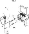
Fig. 1 is a view illustrating a schematic configuration of anendoscope device 100 that is an embodiment of the invention. -
Fig. 2 is a schematic view illustrating an internal configuration of theendoscope device 100 illustrated inFig. 1 . -
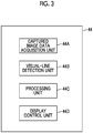
Fig. 3 is a view illustrating functional blocks of asystem control unit 44 of a control device 4 illustrated inFig. 2 . -
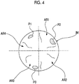
Fig. 4 is a view for explaining the operation of aprocessing unit 44C in thesystem control unit 44 illustrated inFig. 3 . -
Fig. 5 is a view illustrating an example of an image displayed on adisplay device 7 under the control of adisplay control unit 44D in asystem control unit 44 illustrated inFig. 3 . -
Fig. 6 is a flowchart for explaining the operation of thesystem control unit 44 illustrated inFig. 4 . -
Fig. 7 is a flowchart for explaining a first modification example of the operation of thesystem control unit 44 illustrated inFig. 4 . -
Fig. 8 is a view illustrating an example of an image displayed on thedisplay device 7 in Step S4a illustrated inFig. 7 . -
Fig. 9 is a flowchart for explaining a second modification example of the operation of thesystem control unit 44 illustrated inFig. 4 . -
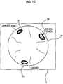
Fig. 10 is a view illustrating an example of an image displayed on thedisplay device 7 in Step S4b illustrated inFig. 9 . -
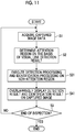
Fig. 11 is a flowchart for explaining a third modification example of the operation of thesystem control unit 44 illustrated inFig. 4 . -
Fig. 12 is a flowchart for explaining a fourth modification example of the operation of thesystem control unit 44 illustrated inFig. 4 . -
Fig. 13 is a flowchart for explaining a fifth modification example of the operation of thesystem control unit 44 illustrated inFig. 4 . - Hereinafter, embodiments of the invention will be described with reference to the drawings.
-
Fig. 1 is a view illustrating a schematic configuration of anendoscope device 100 that is an embodiment of the invention. - As illustrated in
Fig. 1 , theendoscope device 100 comprises anendoscope 1, and abody part 2 including a control device 4 and alight source device 5 to which theendoscope 1 is connected. - A
display device 7 that displays a captured image or the like obtained by imaging the inside of a subject by theendoscope 1, animaging device 8 installed near thedisplay device 7, and aninput unit 6, which is an interface for inputting various kinds of information to the control device 4, are connected to the control device 4. The control device 4 controls theendoscope 1, thelight source device 5, thedisplay device 7, and theimaging device 8. - The
display device 7 has a display surface on which display pixels are two-dimensionally arranged, and pixel data constituting image data is drawn on each display pixel on the display surface, thereby performing display of an image based on the image data. - The
imaging device 8 is provided to detect the visual line of an observer who observes an image displayed on the display surface of thedisplay device 7, and is disposed so as to be able to capture an image in front of the display surface. A visual line detection image data obtained by imaging the subject with theimaging device 8 is transmitted to the control device 4. - The
endoscope 1 comprises aninsertion part 10 that is a tubular member extending in one direction and is inserted into the subject, anoperating part 11 that is provided at a proximal end part of theinsertion part 10 and is provided with operating members for performing an observation mode switching operation, an imaging and recording operation, a forceps operation, an air and water supply operation, a suction operation, and the like, anangle knob 12 provided adjacent to theoperating part 11, and auniversal cord 13 includingconnector parts endoscope 1 to thelight source device 5 and the control device 4, respectively. - In addition, although omitted in
Fig. 1 , various channels, such as a forceps hole for inserting forceps for sampling a living tissue, such as cells or polyps, an air and water supply channel, and a suction channel, are provided inside theoperating part 11 and theinsertion part 10. - The
insertion part 10 is constituted of aflexible part 10A that has flexibility, abending part 10B provided at a distal end of theflexible part 10A, and a harddistal end part 10C provided at a distal end of thebending part 10B. - The
bending part 10B is configured to be bendable by the rotational movement operation of theangle knob 12. Depending on regions of the subject in which theendoscope 1 is used, thebending part 10B can be bent in an optional direction and at an optional angle and thedistal end part 10C can be directed in a desired direction. -
Fig. 2 is a schematic view illustrating an internal configuration of theendoscope device 100 illustrated inFig. 1 . - The
light source device 5 comprises a lightsource control unit 51 and alight source unit 52. - The
light source unit 52 generates illumination light for irradiating the subject. The illumination light emitted from thelight source unit 52 enters alight guide 53 built in theuniversal cord 13, and is emitted to the subject through theillumination lens 50 provided at thedistal end part 10C of theinsertion part 10. - A white light source that emits white light, a plurality of light sources including the white light source and a light source (for example, a blue light source that emits blue light) that emits other color light, or the like is used as the
light source unit 52. A plurality ofillumination lenses 50 may be provided in conformity with the type of light emitted from thelight source unit 52 on the distal end surface of thedistal end part 10C. - The light
source control unit 51 is connected to asystem control unit 44 of the control device 4. The lightsource control unit 51 controls thelight source unit 52 on the basis of a command from thesystem control unit 44. - The
distal end part 10C of theendoscope 1 is provided with an imaging optical system including anobjective lens 21 and alens group 22, animaging element 23 that images the subject through the imaging optical system, an analog/digital converter circuit (ADC) 24, amemory 25, such as a random access memory (RAM), a communication interface (I/F) 26, animaging control unit 27, and thelight guide 53 for guiding the illumination light emitted from thelight source unit 52 to theillumination lens 50. - The
light guide 53 extends from thedistal end part 10C to theconnector part 13A of theuniversal cord 13. The illumination light emitted from thelight source unit 52 of thelight source device 5 is allowed to enter thelight guide 53 in a state where theconnector part 13A of theuniversal cord 13 is connected to thelight source device 5. - As the
imaging element 23, a charge coupled device (CCD) image sensor or a complementary metal oxide semiconductor (CMOS) image sensor is used. - The
imaging element 23 has a light-receiving surface on which a plurality of pixels are two-dimensionally arranged, converts an optical image formed on the light-receiving surface by the above imaging optical system into an electrical signal (imaging signal) in each pixel, and outputs the converted electrical signal to theADC 24. As theimaging element 23, for example, one on which color filters, such as an elementary color or a complementary color, are mounted, is used. A set of the imaging signals output from the respective pixels of the light-receiving surface of theimaging element 23 is referred to as captured image signals. - In addition, in a case where one in which the spectrum of the white light emitted from the white light source is divided in a time-division manner by a plurality of color filters to generate the illumination light is used as the
light source unit 52, one on which no color filter is mounted may be used as theimaging element 23. - The
imaging element 23 may be disposed at thedistal end part 10C in a state where the light-receiving surface is perpendicular to an optical axis Ax of theobjective lens 21, or may be disposed at thedistal end part 10C in a state where the light-receiving surface is parallel to the optical axis Ax of theobjective lens 21. - The imaging optical system provided in the
endoscope 1 is constituted of optical members (including the above lens group 22), such as a lens and a prism, which are present on an optical path of the light from the subject between theimaging element 23 and theobjective lens 21, and theobjective lens 21. There is also a case where the imaging optical system is constituted of only theobjective lens 21. - The
ADC 24 converts the imaging signal output from theimaging element 23 into a digital signal having a predetermined number of bits. - The
memory 25 temporarily records the imaging signal digitally converted by theADC 24. - The communication I/
F 26 is connected to a communication interface (I/F) 41 of the control device 4. The communication I/F 26 transmits the imaging signal recorded in thememory 25 to the control device 4 through a signal line within theuniversal cord 13. - The
imaging control unit 27 is connected to thesystem control unit 44 of the control device 4 via the communication I/F 26. Theimaging control unit 27 controls theimaging element 23, theADC 24, and thememory 25 on the basis of a command from thesystem control unit 44 to be received by the communication I/F 26. - The control device 4 comprises the communication I/
F 41 connected to the communication I/F 26 of theendoscope 1 by theuniversal cord 13, asignal processing unit 42, adisplay controller 43, thesystem control unit 44, and arecording medium 45. - The communication I/
F 41 receives the imaging signal transmitted from the communication I/F 26 of theendoscope 1 and transmits the imaging signal to thesignal processing unit 42. - The
signal processing unit 42 has a memory for temporarily recording the imaging signal received from the communication I/F 41 built therein, and processes captured image signals (image processing, such as demosaicing processing or gamma-correction processing) that are a set of the imaging signals recorded in the memory to generate captured image data in such a format that recognition processing to be described below is allowed. The captured image data generated by thesignal processing unit 42 is recorded on therecording medium 45, such as a hard disk or a flash memory. - The
display controller 43 causes thedisplay device 7 to display a captured image based on the captured image data generated by thesignal processing unit 42. The coordinates of each pixel data constituting the captured image data generated by thesignal processing unit 42 are managed in association with the coordinates of any of the display pixels constituting the display surface of thedisplay device 7. - The
system control unit 44 controls the respective units of the control device 4, and sends commands to theimaging control unit 27 of theendoscope 1 and the lightsource control unit 51 of thelight source device 5, and integrally controls theentire endoscope device 100. - The
system control unit 44 performs the control of theimaging element 23 via theimaging control unit 27. Additionally, thesystem control unit 44 performs the control of thelight source unit 52 via the lightsource control unit 51. - The
system control unit 44 includes various processors that execute a program to perform processing, a random access memory (RAM), and a read only memory (ROM). - The various processors include a central processing unit (CPU) that is a general-purpose processor that executes a program to perform various kinds of processing, a programmable logic device (PLD), which is a processor capable of changing a circuit configuration after manufacture, such as a field programmable gate array (FPGA), or an exclusive electric circuit, which is a processor having a circuit configuration exclusively designed to execute specific processing, such as an application specific integrated circuit (ASIC).
- The structure of these various processors is, more specifically, an electric circuit in which circuit elements, such as semiconductor elements, are combined together.
- The
system control unit 44 may be constituted of one of the various processors, or may be constituted of a combination (for example, a combination of a plurality of FPGAs or a combination of a CPU and an FPGA) of two or more processors of the same type or different types. -
Fig. 3 is a view illustrating functional blocks of thesystem control unit 44 of the control device 4 illustrated inFig. 2 . - The processor of the
system control unit 44 executes an inspection support program stored in the ROM built in thesystem control unit 44, thereby functioning as an inspection support device comprising a captured image data acquisition unit 44A, a visual-line detection unit 44B, aprocessing unit 44C, and adisplay control unit 44D. - The captured image data acquisition unit 44A sequentially acquires the captured image data obtained by processing the imaging signals, which are obtained by imaging the inside of the subject by the
imaging element 23, by thesignal processing unit 42. - The visual-
line detection unit 44B acquires the visual line detection image data transmitted from theimaging device 8, and detects the visual line of the observer (an operator of the endoscope 1) directed to thedisplay device 7 on the basis of images of both eyes of a person included in the visual line detection image data. The visual-line detection unit 44B outputs information of coordinates at which visual lines intersect each other on the display surface of thedisplay device 7, as a visual line detection result. - The
processing unit 44C performs recognition processing, which is the processing for detecting the lesion site from the captured image data and identifying the detected lesion site, on the captured image data acquired by the captured image data acquisition unit 44A. In the recognition processing, processing for detecting the lesion site is referred to as detection processing, and processing for identifying the lesion site is referred to as identification processing. - The detection of the lesion site refers to finding a site suspected of a lesion, such as a malignant tumor or a benign tumor (lesion candidate region), from the captured image data.
- The identification of the lesion site refers to identifying the type, nature, or the like of the detected lesion site, such as whether or not the lesion site detected by the detection processing is malignant or benign, what kind of disease if malignant, or how much the degree of progress of the disease is.
- The above detection processing and identification processing are performed by an image recognition model (for example, a neural network, a support vector machine, or the like) having a hierarchical structure and a parameter for extracting a feature amount determined by machine learning, deep learning, or the like.
- The
processing unit 44C controls the content of the above-described recognition processing performed on the captured image data, on the basis of the visual line detected by the visual-line detection unit 44B. - The
display control unit 44D issues a command to thedisplay controller 43 to perform the control of causing thedisplay device 7 to display the captured image based on the captured image data recorded on therecording medium 45 as a live view image, and the control of causing thedisplay device 7 to display the result of the above recognition processing by theprocessing unit 44C. -
Fig. 4 is a view for explaining the operation of theprocessing unit 44C in thesystem control unit 44 illustrated inFig. 3 .Fig. 4 illustrates the captured image data IM acquired by the captured image data acquisition unit 44A. The captured image data IM illustrated inFig. 4 includes lesion sites P1 to P3. - The
processing unit 44C determines a region (hereinafter, referred to as an attention region) to which an attention is paid on the captured image data IM acquired by the captured image data acquisition unit 44A from the information on the coordinates of the display pixels intersecting with the operator's visual line on the display surface of thedisplay device 7 output from the visual-line detection unit 44B. - For example, as illustrated in
Fig. 4 , theprocessing unit 44C divides the captured image data IM into a total of four regions including a divided region AR1, a divided region AR2, a divided region AR3, and a divided region AR4. - The
processing unit 44C repeatedly performs the processing of specifying the pixel data of the captured image data IM corresponding to the coordinates from the coordinates of the display pixels output from the visual-line detection unit 44B for a fixed period. Then, theprocessing unit 44C determines, as the attention region, a divided region including the largest amount of pixel data specified during this fixed period among the divided regions AR1 to AR4. - The
processing unit 44C executes recognition processing using the above-described image recognition model only on the attention region of the captured image data IM determined in this way, and does not execute the above-described recognition processing on the region (hereinafter, referred to as a non-attention region) of the captured image data IM excluding the attention region. - In
Fig. 4 , a case where the divided region AR4 is determined as the attention region is taken as an example. In this case, the pixel data in the divided region AR4 is input to the image recognition model and the recognition processing is executed, and the recognition processing is not performed on the pixel data in the divided regions AR1 to AR3. - In a case where the pixel data in the divided region AR4 is input to the image recognition model and the recognition processing is performed, the recognition processing allows the lesion site P1 included in the divided region AR4 to be detected and further allows the lesion site P1 to be identified.
- In a case where the
processing unit 44C detects the lesion site P1 and obtains the identification result of the lesion site P1, as illustrated inFig. 5 , thedisplay control unit 44D causes the portion of the lesion site P1 to be displayed in a highlighted manner (highlighted by being enclosed in a thick frame in the example ofFig. 5 ) in a captured image im based on the captured image data IM, and causes the identification result (in the example ofFig. 5 , the text of "cancer,stage 2") to be displayed together with the captured image im. - On the other hand, no recognition processing is performed on the divided regions AR1 to AR3. For that reason, as illustrated in
Fig. 5 , the lesion sites P2 and P3 are not displayed in a highlighted manner or the identification result is not displayed. - In this way, the
processing unit 44C determines which region of the captured image data should be subjected to the recognition processing on the basis of the visual line detected by the visual-line detection unit 44B. - The operation of the
endoscope device 100 configured as described above will be described with reference to a flowchart. -
Fig. 6 is a flowchart for explaining the operation of thesystem control unit 44 illustrated inFig. 4 . - In a case where the capturing of the moving image by the
imaging element 23 is started by the operation of the operatingpart 11, the captured image signals are output from theimaging element 23, the captured image signals are processed, and the captured image data for one frame of the moving image is sequentially generated and recorded on therecording medium 45. Additionally, captured images based on the generated captured image data are sequentially displayed as live view images on thedisplay device 7. Moreover, the visual-line detection unit 44B starts the processing of detecting the visual line of the operator. - In a case where the capturing of the moving image is started, the captured image data acquisition unit 44A acquires the captured image data generated by the signal processing unit 42 (Step S1).
- Next, the
processing unit 44C determines the attention region in the captured image data acquired in Step S1, on the basis of the operator's visual line detected by the visual-line detection unit 44B (Step S2). - Next, the
processing unit 44C executes the above-described recognition processing (detection processing and identification processing) only on the determined attention region (Step S3). - In a case where the recognition processing in Step S3 is completed, the detection result, which is the result of the detection processing, and the identification result, which is the result of the identification processing, are displayed on the
display device 7 together with the captured image as exemplified inFig.5 (Step S4) by the control of thedisplay control unit 44D. - After Step S4, in a case where an instruction to end imaging by the
imaging element 23 is performed and the inspection is ended (Step S5: YES), thesystem control unit 44 ends the processing. On the other hand, in a case where the inspection is continued (Step S5: NO), the processing returns to Step S1, and the subsequent processing is repeated. - As described above, according to the
endoscope device 100, the recognition processing is performed only on the attention region where the visual line of the operator who operates theendoscope 1 is gathered. Even in a situation where both hands are closed, the operator can obtain the detection result and the identification result in the site to which an attention is paid simply by changing the position where the visual line is directed to the captured image, and can perform the inspection efficiently and accurately. - Additionally, according to the
endoscope device 100, the range where the recognition processing is performed can be narrowed. For this reason, the processing load on thesystem control unit 44 can be reduced in a case where the detection of a lesion site and the identification of the lesion site are performed in real time during the endoscopy. In this way, since the processing load can be reduced, a model having higher detection accuracy or identification accuracy of the lesion site can be used as the image recognition model used for the recognition processing, and the accuracy of the endoscopy can be improved. -
Fig. 7 is a flowchart for explaining a first modification example of the operation of thesystem control unit 44 illustrated inFig. 4 . - The flowchart illustrated in
Fig. 7 is the same asFig. 6 except that Step S3 is changed to Steps S3a and S3b and Step S4 is changed to Step S4a. InFig. 7 , the same processing as that inFig. 6 is denoted by the same reference numerals, and the description thereof will be omitted. - In a case where the attention region is determined in Step S2, the
processing unit 44C performs the detection processing using the same image recognition model on each of the attention region in the captured image data and the non-attention region that is a region excluding the attention region, and detects a lesion site. That is, in Step S3a, the detection processing of the lesion site is performed on the entire captured image data (Step S3a). - After the lesion site is detected by the processing of Step S3a, the
processing unit 44C performs the identification processing only on the attention region determined in Step S2 (Step S3b). - After Step S3b, the
display control unit 44D causes thedisplay device 7 to display the result of the detection processing in Step S3a and the result of the identification processing in Step S3b together with the captured image (Step S4a). After Step S4a, the processing proceeds to Step S5. -
Fig. 8 is a view illustrating an example of an image displayed on thedisplay device 7 in Step S4a illustrated inFig. 7 . As illustrated inFig. 8 , the lesion sites P1 to P3 on the captured image im are displayed in a highlighted manner as the detection result of the lesion site. Then, the identification result is displayed only for the lesion site P1 to which the operator's visual line is directed. - In this way, in the first modification example illustrated in
Fig. 7 , theprocessing unit 44C of thesystem control unit 44 performs the detection processing on the entire captured image data, and performs the identification processing only on the attention region. - In this way, in the region to which an attention is paid by the operator, the location of the lesion site and the identification result of the lesion site are displayed. Therefore, this can be used for the determination of the subsequent treatment.
- Additionally, even in a region to which an attention is not paid by the operator, a lesion site is clearly specified in a case where the lesion site is present. For this reason, the possibility that the lesion site is overlooked can be reduced, and the accuracy of the inspection can be improved.
- Additionally, since the identification processing is performed only on the attention region, the processing load on the
system control unit 44 can be reduced, and the inspection accuracy can be improved by adopting highly accurate identification processing. - In the first modification example, in the state illustrated in
Fig. 8 , for example, in a case where the operator wants to know the identification result of the lesion site P2, the operator directs his/her visual line from the lesion site P1 to the lesion site P2, thereby allowing the identification result to be displayed. In this way, the identification result is displayed only when necessary, so that the inspection can be efficiently performed. -
Fig. 9 is a flowchart for explaining a second modification example of the operation of thesystem control unit 44 illustrated inFig. 4 . - The flowchart illustrated in
Fig. 9 is the same as that inFig. 6 except that Step S3 is changed to Step S3c and Step S4 is changed to Step S4b. InFig. 9 , the same processing as that inFig. 6 is denoted by the same reference numerals, and the description thereof will be omitted. - In a case where the attention region is determined in Step S2, the
processing unit 44C performs the recognition processing with different performances on the attention region in the captured image data and the non-attention region that is a region excluding the attention region (Step S3c). - That is, in Step S3c, the
processing unit 44C makes the content of the recognition processing (at least one of the configuration or the parameters of the image recognition model) different between the attention region and the non-attention region of the captured image data. - Specifically, the
processing unit 44C controls the content of the recognition processing on the attention region such that the performance of the recognition processing is higher than the performance of the recognition processing on the non-attention region. - For example, in the case of detection processing, the higher the resolution of image data that can be analyzed by the image recognition model, the higher the performance of the detection processing. Alternatively, the greater the number of layers of the image recognition model, the higher the performance of the detection processing.
- Additionally, in the case of the identification processing, the performance of the identification processing is higher as the type of information that can be output as a result by the image recognition model is more. Alternatively, the higher the number of layers of the image recognition model, the higher the performance of the identification processing. Alternatively, the higher the resolution of the image data that can be analyzed by the image recognition model, the higher the performance of the identification processing.
- After Step S3c, the
display control unit 44D causes thedisplay device 7 to display the result of the recognition processing in Step S3c together with the captured image (Step S4b). After Step S4b, the processing proceeds to Step S5. -
Fig. 10 is a view illustrating an example of an image displayed on thedisplay device 7 in Step S4b illustrated inFig. 9 . - As illustrated in
Fig. 10 , the lesion sites P1 to P3 on the captured image im are displayed in a highlighted manner as detection results thereof. Also, for the lesion site P1 to which the operator's visual line is directed, information on the stage of the cancer is displayed in addition to the type (cancer) of tumor as the identification result. On the other hand, for the lesion sites P2 and P3 to which the operator's visual line is not directed, only the type of tumor is displayed. - In this way, the recognition processing with relatively high performance is performed on the region of the captured image to which the operator's visual line is directed, so that the inspection can be efficiently advanced. Additionally, the recognition processing with relatively low performance is performed even on a region of the captured image to which the operator's visual line is not directed, so that a lesion site can be prevented from being overlooked and the inspection efficiency can be improved.
-
Fig. 11 is a flowchart for explaining a third modification example of the operation of thesystem control unit 44 illustrated inFig. 4 . - The flowchart illustrated in
Fig. 11 is the same as that inFig. 6 except that Step S3 is changed to Step S31 and Step S4 is changed to Step S41. InFig. 11 , the same processing as that inFig. 6 is denoted by the same reference numerals, and the description thereof will be omitted. - In a case where the attention region is determined in Step S2, the
processing unit 44C performs the identification processing only on the non-attention region which is a region excluding the attention region in the captured image data (Step S31). - After Step S31, the
display control unit 44D causes thedisplay device 7 to display the result of the recognition processing in Step S31 together with the captured image (Step S41). After Step S41, the processing proceeds to Step S5. - In the third modification example, the recognition processing is performed only on a region of the captured image to which an attention is not paid by the operator, and the result is displayed. Operators are often skilled physicians. For this reason, regarding the region of the captured image visually observed by the operator, it can be considered that the detection of the lesion and the identification of the lesion are performed with high accuracy through the experience of the operator.
- Thus, as in the third modification example, the identification processing is performed only on the region where the visual line is not directed, so that a lesion site that cannot be detected through the operator's experience can be prevented from being overlooked and the accuracy of the inspection can be enhanced. Additionally, according to the third modification example, a range in which the identification processing is performed is narrowed. Therefore, the accuracy of the identification processing can be increased, and the processing load on the
system control unit 44 can be reduced. -
Fig. 12 is a flowchart for explaining a fourth modification example of the operation of thesystem control unit 44 illustrated inFig. 4 . - The flowchart illustrated in
Fig. 12 is the same as that inFig. 7 except that Step S3b is changed to Step S32 and Step S4a is changed to Step S42. InFig. 12 , the same processing as that inFig. 7 is denoted by the same reference numerals, and the description thereof will be omitted. - After the lesion site is detected by the processing in Step S3a, the
processing unit 44C performs the identification processing only on the non-attention region that is a region excluding the attention region determined in Step S2 (Step S32). - After Step S32, the
display control unit 44D causes thedisplay device 7 to display the result of the detection processing in Step S3a and the result of the identification processing in Step S32 together with the captured image (Step S42). - According to the fourth modification example, in a region to which an attention is not paid by the operator, the location of the lesion site and the identification result of the lesion site are displayed. For this reason, this can be used for the determination of the subsequent treatment.
- Additionally, even in the region to which an attention is paid by the operator, a lesion site can be clearly specified in a case where the lesion site is present. For this reason, the possibility that the lesion site is overlooked can be reduced, and the accuracy of the inspection can be improved.
- Additionally, since the identification processing is performed only on the non-attention region, the processing load on the
system control unit 44 can be reduced, and the inspection accuracy can be improved by adopting highly accurate identification processing. -
Fig. 13 is a flowchart for explaining a fifth modification example of the operation of thesystem control unit 44 illustrated inFig. 4 . - The flowchart illustrated in
Fig. 13 is the same as that inFig. 9 except that Step S3c is changed to Step S33 and Step S4b is changed to Step S43. InFig. 13 , the same processing as that inFig. 9 is denoted by the same reference numerals, and the description thereof will be omitted. - In a case where the attention region is determined in Step S2, the
processing unit 44C performs the recognition processing with different performances on the attention region in the captured image data and the non-attention region that is a region excluding the attention region (Step S33). - That is, in Step S33, the
processing unit 44C makes the content of the recognition processing (at least one of the configuration or the parameters of the image recognition model) different between the attention region and the non-attention region of the captured image data. - Specifically, the
processing unit 44C controls the content of the recognition processing on the attention region such that the performance of the recognition processing is higher than the performance of the recognition processing on the non-attention region. - After Step S33, the
display control unit 44D causes thedisplay device 7 to display the result of the recognition processing in Step S33 together with the captured image (Step S43). After Step S43, the processing proceeds to Step S5. - According to the fifth modification example, the recognition processing with relatively high performance is performed on a region of the captured image to which the operator's visual line is not directed. Therefore, a lesion site can be efficiently prevented from being overlooked, and the inspection can be efficiently performed. Additionally, the recognition processing with relatively low performance is performed even on a region of the captured image to which the operator's visual line is directed, so that a lesion site can be prevented from being overlooked and the inspection efficiency can be improved.
- In configurations other than the modification examples described with reference to
Figs. 7 and12 , the identification processing is not essential as the recognition processing performed by theprocessing unit 44C. Even in a case where theprocessing unit 44C performs only the detection processing, it is possible to obtain the effects of reducing the processing load on thesystem control unit 44, improving the accuracy of the detection processing, improving the inspection efficiency, and the like. - In the above description, the visual line of the operator is detected on the basis of the image data obtained by imaging the subject with the
imaging device 8. However, the method of detecting the visual line is not limited to this, and various well-known methods can be adopted. For example, the visual line can be detected on the basis of the detection information of an acceleration sensor mounted on a glasses-type wearable terminal worn by the operator. - As described above, the following matters are disclosed in the present specification.
- (1) An inspection support device comprising a captured image data acquisition unit that acquires captured image data obtained by imaging the inside of a subject with an endoscope; a visual-line detection unit that detects a visual line directed to a display device that displays a captured image based on the captured image data; a processing unit that performs processing for performing at least detection of the detection of a lesion site from the captured image data and identification of the detected lesion site on the captured image data; and a display control unit that causes the display device to display a result of the processing by the processing unit, wherein the processing unit controls a content of the processing on the captured image data on the basis of the visual line detected by the visual-line detection unit.
- (2) The inspection support device according to (1), wherein the processing unit determines an attention region to which an attention is paid in the captured image data on the basis of the visual line detected by the visual-line detection unit, does not execute the processing only on the attention region, and executes the processing only on a non-attention region that is a region excluding the attention region in the captured image data.
- (3) The inspection support device according to (1), wherein the processing unit performs the processing for detecting the lesion site on the entire captured image data, determine an attention region to which an attention is paid in the captured image data on the basis of the visual line detected by the visual-line detection unit, and performs the processing for identifying the lesion site only on the attention region.
- (4) The inspection support device according to (1), wherein the processing unit determines an attention region to which an attention is paid in the captured image data on the basis of the visual line detected by the visual-line detection unit, executes the processing on the entire captured image data, and makes a content of the processing on the attention region in the captured image data different from a content of the processing on a non-attention region, which is a region excluding the attention region in the captured image data.
- (5) The inspection support device according to (4), wherein the processing unit controls the content of the processing on the attention region such that performance of the processing is higher than performance of the processing on the non-attention region.
- (6) The inspection support device according to (1), wherein the processing unit determines an attention region to which an attention is paid in the captured image data on the basis of the visual line detected by the visual-line detection unit, does not execute the processing on the attention region, and executes the processing only on a non-attention region that is a region excluding the attention region in the captured image data.
- (7) The inspection support device according to (1), wherein the processing unit determines an attention region to which an attention is paid in the captured image data on the basis of the visual line detected by the visual-line detection unit, and performs the processing for detecting the lesion site on the entire captured image data, and executes the processing for identifying the lesion site only on a non-attention region that is a region excluding the attention region in the captured image data.
- (8) The inspection support device according to (4), wherein the processing unit controls the content of the processing on the non-attention region such that performance of the processing is higher than performance of the processing on the attention region.
- (9) An endoscope device comprising: the inspection support device according to any one of (1) to (8); and the endoscope.
- (10) An inspection support method comprising: a captured image data acquisition step of acquiring captured image data obtained by imaging the inside of a subject with an endoscope; a visual-line detection step of detecting a visual line directed to a display device that displays a captured image based on the captured image data; a processing step of performing processing for performing at least a detection of a lesion site from the captured image data out of the detection of the lesion site and identification of the detected lesion site on the captured image data; and a display control step of causing the display device to display a result of the processing by the processing step, wherein in the processing step, a content of the processing on the captured image data is controlled on the basis of the visual line detected by the visual-line detection step.
- (11) An inspection support program for causing a computer execute a captured image data acquisition step of acquiring captured image data obtained by imaging the inside of a subject with an endoscope; a visual-line detection step of detecting a visual line directed to a display device that displays a captured image based on the captured image data; a processing step of performing processing for performing at least a detection of a lesion site from the captured image data out of the detection of the lesion site and identification of the detected lesion site on the captured image data; and a display control step of causing the display device to display a result of the processing by the processing step, wherein in the processing step, a content of the processing on the captured image data is controlled on the basis of the visual line detected by the visual-line detection step.
- According to the invention, it is possible to provide the inspection support device, the endoscope device, the inspection support method, and the inspection support program that can make both the accuracy and efficiency of the inspection using the endoscope compatible. Explanation of References
-
- 100:
- endoscope device
- 1:
- endoscope
- 2:
- body part
- 10:
- insertion part
- 10A:
- flexible part
- 10B:
- bending part
- 10C:
- distal end part
- 11:
- operating Part
- 12:
- angle knob
- 13:
- universal cord
- 13A, 13B:
- connector part
- 6:
- input unit
- 7:
- display device
- 8:
- imaging device
- 21:
- objective lens
- Ax:
- optical axis
- 22:
- lens group
- 23:
- imaging element
- 24:
- ADC
- 25:
- memory
- 26:
- communication interface
- 27:
- imaging control unit
- 4:
- control device
- 41:
- communication interface
- 42:
- signal processing unit
- 43:
- display controller
- 44:
- system control unit
- 44A:
- captured image data acquisition unit
- 44B:
- visual-line detection unit
- 44C:
- processing unit
- 44D:
- display control unit
- 45:
- recording medium
- 5:
- light source device
- 50:
- illumination lens
- 51:
- light source control unit
- 52:
- light source unit
- 53:
- light guide
- IM:
- captured image data
- im:
- captured image
- AR1, AR2, AR3, AR4:
- divided region
- P1, P2, P3:
- lesion site
Claims (11)
- An inspection support device comprising:a captured image data acquisition unit that acquires captured image data obtained by imaging the inside of a subject with an endoscope;a visual-line detection unit that detects a visual line directed to a display device that displays a captured image based on the captured image data;a processing unit that performs processing for performing at least a detection of a lesion site from the captured image data out of the detection of the lesion site and identification of the detected lesion site on the captured image data; anda display control unit for causing the display device to display a result of the processing by the processing unit,wherein the processing unit controls a content of the processing on the captured image data on the basis of the visual line detected by the visual-line detection unit.
- The inspection support device according to claim 1,
wherein the processing unit determines an attention region to which an attention is paid in the captured image data on the basis of the visual line detected by the visual-line detection unit, does not execute the processing on a non-attention region that is a region excluding the attention region in the captured image data, and executes the processing only on the attention region. - The inspection support device according to claim 1,
wherein the processing unit performs the processing for detecting the lesion site on the entire captured image data, determine an attention region to which an attention is paid in the captured image data on the basis of the visual line detected by the visual-line detection unit, and performs the processing for identifying the lesion site only on the attention region. - The inspection support device according to claim 1,
wherein the processing unit determines an attention region to which an attention is paid in the captured image data on the basis of the visual line detected by the visual-line detection unit, executes the processing on the entire captured image data, and makes a content of the processing on the attention region in the captured image data different from a content of the processing on a non-attention region, which is a region excluding the attention region in the captured image data. - The inspection support device according to claim 4,
wherein the processing unit controls the content of the processing on the attention region such that performance of the processing is higher than performance of the processing on the non-attention region. - The inspection support device according to claim 1,
wherein the processing unit determines an attention region to which an attention is paid in the captured image data on the basis of the visual line detected by the visual-line detection unit, does not execute the processing on the attention region, and executes the processing only on a non-attention region that is a region excluding the attention region in the captured image data. - The inspection support device according to claim 1,
wherein the processing unit determines an attention region to which an attention is paid in the captured image data on the basis of the visual line detected by the visual-line detection unit, and performs the processing for detecting the lesion site on the entire captured image data, and executes the processing for identifying the lesion site only on a non-attention region that is a region excluding the attention region in the captured image data. - The inspection support device according to claim 4,
wherein the processing unit controls the content of the processing on the non-attention region such that performance of the processing is higher than performance of the processing on the attention region. - An endoscope device comprising:the inspection support device according to any one of claims 1 to 8; andthe endoscope.
- An inspection support method comprising:a captured image data acquisition step of acquiring captured image data obtained by imaging the inside of a subject with an endoscope;a visual-line detection step of detecting a visual line directed to a display device that displays a captured image based on the captured image data;a processing step of performing processing for performing at least a detection of a lesion site from the captured image data out of the detection of the lesion site and identification of the detected lesion site on the captured image data; anda display control step of causing the display device to display a result of the processing by the processing step,wherein in the processing step, a content of the processing on the captured image data is controlled on the basis of the visual line detected by the visual-line detection step.
- An inspection support program for causing a computer to executea captured image data acquisition step of acquiring captured image data obtained by imaging the inside of a subject with an endoscope,a visual-line detection step of detecting a visual line directed to a display device that displays a captured image based on the captured image data,a processing step of performing processing for performing at least a detection of a lesion site from the captured image data out of the detection of the lesion site and identification of the detected lesion site on the captured image data, anda display control step of causing the display device to display a result of the processing by the processing step,wherein in the processing step, a content of the processing on the captured image data is controlled on the basis of the visual line detected by the visual-line detection step.
Applications Claiming Priority (2)
| Application Number | Priority Date | Filing Date | Title |
|---|---|---|---|
| JP2017210379 | 2017-10-31 | ||
| PCT/JP2018/038754 WO2019087790A1 (en) | 2017-10-31 | 2018-10-18 | Inspection assistance device, endoscope device, inspection assistance method, and inspection assistance program |
Publications (3)
| Publication Number | Publication Date |
|---|---|
| EP3705024A1 true EP3705024A1 (en) | 2020-09-09 |
| EP3705024A4 EP3705024A4 (en) | 2020-11-11 |
| EP3705024B1 EP3705024B1 (en) | 2025-07-02 |
Family
ID=66333201
Family Applications (1)
| Application Number | Title | Priority Date | Filing Date |
|---|---|---|---|
| EP18873241.6A Active EP3705024B1 (en) | 2017-10-31 | 2018-10-18 | Inspection assistance device, endoscope device, inspection assistance method, and inspection assistance program |
Country Status (5)
| Country | Link |
|---|---|
| US (1) | US11302092B2 (en) |
| EP (1) | EP3705024B1 (en) |
| JP (1) | JP6967602B2 (en) |
| CN (1) | CN111295127B (en) |
| WO (1) | WO2019087790A1 (en) |
Families Citing this family (12)
| Publication number | Priority date | Publication date | Assignee | Title |
|---|---|---|---|---|
| CN109427060A (en) * | 2018-10-30 | 2019-03-05 | 腾讯科技(深圳)有限公司 | A kind of method, apparatus, terminal device and the medical system of image identification |
| US20210407077A1 (en) * | 2018-12-04 | 2021-12-30 | Hoya Corporation | Information processing device and model generation method |
| JP7015275B2 (en) * | 2018-12-04 | 2022-02-02 | Hoya株式会社 | Model generation method, teacher data generation method, and program |
| CN110132547A (en) * | 2019-05-14 | 2019-08-16 | 杭州电子科技大学 | A kind of endoscope head optical performance detecting device and detection method |
| EP3998931A4 (en) * | 2019-07-16 | 2023-04-19 | Docbot, Inc. | REAL-TIME DEPLOYMENT OF MACHINE LEARNING SYSTEMS |
| JP7214876B2 (en) * | 2019-08-09 | 2023-01-30 | 富士フイルム株式会社 | Endoscope device, control method, control program, and endoscope system |
| JP7373335B2 (en) * | 2019-09-18 | 2023-11-02 | 富士フイルム株式会社 | Medical image processing device, processor device, endoscope system, operating method of medical image processing device, and program |
| EP4094672A4 (en) | 2020-01-21 | 2023-01-11 | NEC Corporation | OPERATION SUPPORT DEVICE, OPERATION SUPPORT METHOD AND COMPUTER READABLE RECORDING MEDIA |
| US12070232B2 (en) | 2020-08-10 | 2024-08-27 | Kunnskap Medical, LLC | Endoscopic system with component control |
| JP7476814B2 (en) * | 2021-01-28 | 2024-05-01 | トヨタ自動車株式会社 | Inspection Equipment |
| US12489964B2 (en) * | 2021-07-27 | 2025-12-02 | International Business Machines Corporation | Path planning |
| WO2025173164A1 (en) * | 2024-02-15 | 2025-08-21 | 日本電気株式会社 | Endoscopic inspection assistance device, endoscopic inspection assistance method, and recording medium |
Family Cites Families (32)
| Publication number | Priority date | Publication date | Assignee | Title |
|---|---|---|---|---|
| IT1194149B (en) * | 1983-03-07 | 1988-09-14 | Michele Testa | PROCEDURE FOR THE DETERMINATION OF THE OXIDATIVE ACTIVITY OF A BIOLOGICAL LIQUID AND RELATIVE REAGENT |
| JP4298151B2 (en) | 2000-01-13 | 2009-07-15 | 富士フイルム株式会社 | Fluorescent image display method and apparatus |
| JP2001258802A (en) | 2000-03-16 | 2001-09-25 | Matsushita Electric Ind Co Ltd | Gas powered vacuum cleaner |
| JP2005034211A (en) | 2003-07-16 | 2005-02-10 | Fuji Photo Film Co Ltd | Image discrimination device, method using it and program |
| US20090312817A1 (en) * | 2003-11-26 | 2009-12-17 | Wicab, Inc. | Systems and methods for altering brain and body functions and for treating conditions and diseases of the same |
| US20050240882A1 (en) * | 2004-04-21 | 2005-10-27 | Ge Medical Systems Information Technologies, Inc. | Method and system for displaying regions of pathological interest |
| CA2587804A1 (en) * | 2007-05-08 | 2008-11-08 | William K. Mccroskey | Modular multi-modal tomographic detector and system |
| JP2008301968A (en) * | 2007-06-06 | 2008-12-18 | Olympus Medical Systems Corp | Endoscopic image processing device |
| CN101185603A (en) * | 2007-06-22 | 2008-05-28 | 北京眼吧科技有限公司 | Stereovision training system and method |
| DE102009010263B4 (en) * | 2009-02-24 | 2011-01-20 | Reiner Kunz | Method for navigating an endoscopic instrument during technical endoscopy and associated device |
| JP5529480B2 (en) * | 2009-09-29 | 2014-06-25 | 富士フイルム株式会社 | Medical image diagnosis support device |
| JP5535725B2 (en) * | 2010-03-31 | 2014-07-02 | 富士フイルム株式会社 | Endoscope observation support system, endoscope observation support device, operation method thereof, and program |
| JP2012095274A (en) * | 2010-10-28 | 2012-05-17 | Fujifilm Corp | Stereoscopic image display device and stereoscopic image display method |
| JP5663283B2 (en) * | 2010-12-02 | 2015-02-04 | オリンパス株式会社 | Endoscopic image processing apparatus and program |
| US20130023767A1 (en) * | 2011-05-12 | 2013-01-24 | Mammone Richard J | Low-cost, high fidelity ultrasound system |
| JP6103827B2 (en) * | 2012-06-14 | 2017-03-29 | オリンパス株式会社 | Image processing apparatus and stereoscopic image observation system |
| JP6113460B2 (en) | 2012-11-09 | 2017-04-12 | 東芝メディカルシステムズ株式会社 | Medical image processing apparatus and medical image diagnostic apparatus |
| JP6112861B2 (en) * | 2012-12-28 | 2017-04-12 | キヤノン株式会社 | SUBJECT INFORMATION ACQUISITION DEVICE, SIGNAL PROCESSING DEVICE, AND DISPLAY DEVICE |
| JP6389299B2 (en) * | 2013-09-26 | 2018-09-12 | 富士フイルム株式会社 | Endoscope system, processor device for endoscope system, method for operating endoscope system, method for operating processor device |
| JP6264087B2 (en) * | 2014-02-21 | 2018-01-24 | ソニー株式会社 | Display control device, display device, and display control system |
| EP3108801A4 (en) * | 2014-02-21 | 2017-10-25 | Sony Corporation | Head-mounted display, control device, and control method |
| CN104055478B (en) * | 2014-07-08 | 2016-02-03 | 金纯� | Based on the medical endoscope control system that Eye-controlling focus controls |
| WO2016057960A1 (en) * | 2014-10-10 | 2016-04-14 | Radish Medical Solutions, Inc. | Apparatus, system and method for cloud based diagnostics and image archiving and retrieval |
| WO2016092941A1 (en) * | 2014-12-12 | 2016-06-16 | オリンパス株式会社 | Capsule endoscope system and image capture method thereof |
| CN105992546B (en) * | 2015-01-21 | 2018-08-28 | Hoya株式会社 | Endoscopy system |
| DE112015006338T5 (en) * | 2015-04-21 | 2017-11-30 | Olympus Corporation | endoscopic device |
| WO2017042812A2 (en) * | 2015-09-10 | 2017-03-16 | Magentiq Eye Ltd. | A system and method for detection of suspicious tissue regions in an endoscopic procedure |
| WO2017057574A1 (en) * | 2015-09-29 | 2017-04-06 | 富士フイルム株式会社 | Image processing apparatus, endoscope system, and image processing method |
| JP2017070636A (en) * | 2015-10-09 | 2017-04-13 | ソニー株式会社 | Surgical operation system, surgical operation control device, and surgical operation control method |
| EP3360461A4 (en) * | 2015-11-10 | 2019-05-08 | Olympus Corporation | Endoscope device |
| JP6744712B2 (en) | 2015-12-17 | 2020-08-19 | 富士フイルム株式会社 | Endoscope system, processor device, and method of operating endoscope system |
| CN108778093B (en) * | 2016-04-19 | 2021-01-05 | 奥林巴斯株式会社 | Endoscope system |
-
2018
- 2018-10-18 EP EP18873241.6A patent/EP3705024B1/en active Active
- 2018-10-18 JP JP2019551062A patent/JP6967602B2/en active Active
- 2018-10-18 WO PCT/JP2018/038754 patent/WO2019087790A1/en not_active Ceased
- 2018-10-18 CN CN201880070441.5A patent/CN111295127B/en active Active
-
2020
- 2020-04-08 US US16/842,761 patent/US11302092B2/en active Active
Also Published As
| Publication number | Publication date |
|---|---|
| US11302092B2 (en) | 2022-04-12 |
| JP6967602B2 (en) | 2021-11-17 |
| EP3705024A4 (en) | 2020-11-11 |
| CN111295127A (en) | 2020-06-16 |
| WO2019087790A1 (en) | 2019-05-09 |
| CN111295127B (en) | 2022-10-25 |
| EP3705024B1 (en) | 2025-07-02 |
| JPWO2019087790A1 (en) | 2020-11-12 |
| US20200234070A1 (en) | 2020-07-23 |
Similar Documents
| Publication | Publication Date | Title |
|---|---|---|
| EP3705024B1 (en) | Inspection assistance device, endoscope device, inspection assistance method, and inspection assistance program | |
| JP7630560B2 (en) | Medical image processing device, medical image processing system, operation method of medical image processing device, and medical image processing program | |
| JP6348078B2 (en) | Branch structure determination apparatus, operation method of branch structure determination apparatus, and branch structure determination program | |
| EP3936026B1 (en) | Medical image processing device, processor device, endoscopic system, medical image processing method, and program | |
| JP7326308B2 (en) | MEDICAL IMAGE PROCESSING APPARATUS, OPERATION METHOD OF MEDICAL IMAGE PROCESSING APPARATUS, ENDOSCOPE SYSTEM, PROCESSOR DEVICE, DIAGNOSTIC SUPPORT DEVICE, AND PROGRAM | |
| JPWO2020012872A1 (en) | Medical image processing equipment, medical image processing system, medical image processing method, and program | |
| JP6949999B2 (en) | Image processing equipment, endoscopic systems, image processing methods, programs and recording media | |
| JP7335157B2 (en) | LEARNING DATA GENERATION DEVICE, OPERATION METHOD OF LEARNING DATA GENERATION DEVICE, LEARNING DATA GENERATION PROGRAM, AND MEDICAL IMAGE RECOGNITION DEVICE | |
| JP6254053B2 (en) | Endoscopic image diagnosis support apparatus, system and program, and operation method of endoscopic image diagnosis support apparatus | |
| EP3932290B1 (en) | Medical image processing device, processor device, endoscope system, medical image processing method, and program | |
| US11423318B2 (en) | System and methods for aggregating features in video frames to improve accuracy of AI detection algorithms | |
| WO2015035229A2 (en) | Apparatuses and methods for mobile imaging and analysis | |
| US20200184644A1 (en) | Medical image processing device and medical image processing method | |
| WO2006087981A1 (en) | Medical image processing device, lumen image processing device, lumen image processing method, and programs for them | |
| JPWO2020184257A1 (en) | Medical image processing equipment and methods | |
| JPWO2019087969A1 (en) | Endoscopic systems, notification methods, and programs | |
| WO2019088008A1 (en) | Image processing apparatus, image processing method, program, and endoscope system | |
| JP7289241B2 (en) | Filing device, filing method and program | |
| US20230410304A1 (en) | Medical image processing apparatus, medical image processing method, and program | |
| JP6745748B2 (en) | Endoscope position specifying device, its operating method and program | |
| KR101626802B1 (en) | Lesion Tracking and Monitoring System for Endoscopy | |
| WO2023039493A1 (en) | System and methods for aggregating features in video frames to improve accuracy of ai detection algorithms | |
| US12444052B2 (en) | Learning apparatus, learning method, program, trained model, and endoscope system | |
| WO2022208615A1 (en) | Image processing device, image processing method, and storage medium | |
| CN120694585A (en) | Cavity display method and device, image processing equipment and storage medium |
Legal Events
| Date | Code | Title | Description |
|---|---|---|---|
| STAA | Information on the status of an ep patent application or granted ep patent |
Free format text: STATUS: THE INTERNATIONAL PUBLICATION HAS BEEN MADE |
|
| PUAI | Public reference made under article 153(3) epc to a published international application that has entered the european phase |
Free format text: ORIGINAL CODE: 0009012 |
|
| STAA | Information on the status of an ep patent application or granted ep patent |
Free format text: STATUS: REQUEST FOR EXAMINATION WAS MADE |
|
| 17P | Request for examination filed |
Effective date: 20200408 |
|
| AK | Designated contracting states |
Kind code of ref document: A1 Designated state(s): AL AT BE BG CH CY CZ DE DK EE ES FI FR GB GR HR HU IE IS IT LI LT LU LV MC MK MT NL NO PL PT RO RS SE SI SK SM TR |
|
| AX | Request for extension of the european patent |
Extension state: BA ME |
|
| REG | Reference to a national code |
Ref country code: DE Ref legal event code: R079 Free format text: PREVIOUS MAIN CLASS: A61B0001045000 Ipc: A61B0001000000 |
|
| A4 | Supplementary search report drawn up and despatched |
Effective date: 20201009 |
|
| RIC1 | Information provided on ipc code assigned before grant |
Ipc: G06T 7/00 20170101ALI20201005BHEP Ipc: A61B 1/00 20060101AFI20201005BHEP Ipc: G06K 9/20 20060101ALI20201005BHEP Ipc: G02B 23/24 20060101ALI20201005BHEP Ipc: H04N 7/18 20060101ALI20201005BHEP |
|
| DAV | Request for validation of the european patent (deleted) | ||
| DAX | Request for extension of the european patent (deleted) | ||
| RAP3 | Party data changed (applicant data changed or rights of an application transferred) |
Owner name: FUJIFILM CORPORATION |
|
| STAA | Information on the status of an ep patent application or granted ep patent |
Free format text: STATUS: EXAMINATION IS IN PROGRESS |
|
| 17Q | First examination report despatched |
Effective date: 20230223 |
|
| GRAP | Despatch of communication of intention to grant a patent |
Free format text: ORIGINAL CODE: EPIDOSNIGR1 |
|
| STAA | Information on the status of an ep patent application or granted ep patent |
Free format text: STATUS: GRANT OF PATENT IS INTENDED |
|
| INTG | Intention to grant announced |
Effective date: 20250203 |
|
| RIC1 | Information provided on ipc code assigned before grant |
Ipc: H04N 7/18 20060101ALI20250124BHEP Ipc: G06T 7/00 20170101ALI20250124BHEP Ipc: G06V 10/22 20220101ALI20250124BHEP Ipc: G02B 23/24 20060101ALI20250124BHEP Ipc: A61B 1/00 20060101AFI20250124BHEP |
|
| GRAS | Grant fee paid |
Free format text: ORIGINAL CODE: EPIDOSNIGR3 |
|
| GRAA | (expected) grant |
Free format text: ORIGINAL CODE: 0009210 |
|
| STAA | Information on the status of an ep patent application or granted ep patent |
Free format text: STATUS: THE PATENT HAS BEEN GRANTED |
|
| AK | Designated contracting states |
Kind code of ref document: B1 Designated state(s): AL AT BE BG CH CY CZ DE DK EE ES FI FR GB GR HR HU IE IS IT LI LT LU LV MC MK MT NL NO PL PT RO RS SE SI SK SM TR |
|
| P01 | Opt-out of the competence of the unified patent court (upc) registered |
Free format text: CASE NUMBER: APP_24695/2025 Effective date: 20250523 |
|
| REG | Reference to a national code |
Ref country code: GB Ref legal event code: FG4D |
|
| REG | Reference to a national code |
Ref country code: CH Ref legal event code: EP |
|
| REG | Reference to a national code |
Ref country code: DE Ref legal event code: R096 Ref document number: 602018083293 Country of ref document: DE |
|
| REG | Reference to a national code |
Ref country code: IE Ref legal event code: FG4D |
|
| REG | Reference to a national code |
Ref country code: NL Ref legal event code: MP Effective date: 20250702 |
|
| PG25 | Lapsed in a contracting state [announced via postgrant information from national office to epo] |
Ref country code: PT Free format text: LAPSE BECAUSE OF FAILURE TO SUBMIT A TRANSLATION OF THE DESCRIPTION OR TO PAY THE FEE WITHIN THE PRESCRIBED TIME-LIMIT Effective date: 20251103 |
|
| PG25 | Lapsed in a contracting state [announced via postgrant information from national office to epo] |
Ref country code: NL Free format text: LAPSE BECAUSE OF FAILURE TO SUBMIT A TRANSLATION OF THE DESCRIPTION OR TO PAY THE FEE WITHIN THE PRESCRIBED TIME-LIMIT Effective date: 20250702 |
|
| REG | Reference to a national code |
Ref country code: AT Ref legal event code: MK05 Ref document number: 1808264 Country of ref document: AT Kind code of ref document: T Effective date: 20250702 |
|
| PG25 | Lapsed in a contracting state [announced via postgrant information from national office to epo] |
Ref country code: IS Free format text: LAPSE BECAUSE OF FAILURE TO SUBMIT A TRANSLATION OF THE DESCRIPTION OR TO PAY THE FEE WITHIN THE PRESCRIBED TIME-LIMIT Effective date: 20251102 |
|
| PGFP | Annual fee paid to national office [announced via postgrant information from national office to epo] |
Ref country code: DE Payment date: 20250902 Year of fee payment: 8 |
|
| PG25 | Lapsed in a contracting state [announced via postgrant information from national office to epo] |
Ref country code: NO Free format text: LAPSE BECAUSE OF FAILURE TO SUBMIT A TRANSLATION OF THE DESCRIPTION OR TO PAY THE FEE WITHIN THE PRESCRIBED TIME-LIMIT Effective date: 20251002 |
|
| REG | Reference to a national code |
Ref country code: LT Ref legal event code: MG9D |
|
| PG25 | Lapsed in a contracting state [announced via postgrant information from national office to epo] |
Ref country code: AT Free format text: LAPSE BECAUSE OF FAILURE TO SUBMIT A TRANSLATION OF THE DESCRIPTION OR TO PAY THE FEE WITHIN THE PRESCRIBED TIME-LIMIT Effective date: 20250702 |
|
| PG25 | Lapsed in a contracting state [announced via postgrant information from national office to epo] |
Ref country code: FI Free format text: LAPSE BECAUSE OF FAILURE TO SUBMIT A TRANSLATION OF THE DESCRIPTION OR TO PAY THE FEE WITHIN THE PRESCRIBED TIME-LIMIT Effective date: 20250702 |
|
| PG25 | Lapsed in a contracting state [announced via postgrant information from national office to epo] |
Ref country code: HR Free format text: LAPSE BECAUSE OF FAILURE TO SUBMIT A TRANSLATION OF THE DESCRIPTION OR TO PAY THE FEE WITHIN THE PRESCRIBED TIME-LIMIT Effective date: 20250702 |
|
| PG25 | Lapsed in a contracting state [announced via postgrant information from national office to epo] |
Ref country code: GR Free format text: LAPSE BECAUSE OF FAILURE TO SUBMIT A TRANSLATION OF THE DESCRIPTION OR TO PAY THE FEE WITHIN THE PRESCRIBED TIME-LIMIT Effective date: 20251003 |
|
| PG25 | Lapsed in a contracting state [announced via postgrant information from national office to epo] |
Ref country code: SE Free format text: LAPSE BECAUSE OF FAILURE TO SUBMIT A TRANSLATION OF THE DESCRIPTION OR TO PAY THE FEE WITHIN THE PRESCRIBED TIME-LIMIT Effective date: 20250702 Ref country code: CZ Free format text: LAPSE BECAUSE OF FAILURE TO SUBMIT A TRANSLATION OF THE DESCRIPTION OR TO PAY THE FEE WITHIN THE PRESCRIBED TIME-LIMIT Effective date: 20250702 |
|
| PG25 | Lapsed in a contracting state [announced via postgrant information from national office to epo] |
Ref country code: LV Free format text: LAPSE BECAUSE OF FAILURE TO SUBMIT A TRANSLATION OF THE DESCRIPTION OR TO PAY THE FEE WITHIN THE PRESCRIBED TIME-LIMIT Effective date: 20250702 |
|
| PG25 | Lapsed in a contracting state [announced via postgrant information from national office to epo] |
Ref country code: BG Free format text: LAPSE BECAUSE OF FAILURE TO SUBMIT A TRANSLATION OF THE DESCRIPTION OR TO PAY THE FEE WITHIN THE PRESCRIBED TIME-LIMIT Effective date: 20250702 Ref country code: PL Free format text: LAPSE BECAUSE OF FAILURE TO SUBMIT A TRANSLATION OF THE DESCRIPTION OR TO PAY THE FEE WITHIN THE PRESCRIBED TIME-LIMIT Effective date: 20250702 |
|
| PG25 | Lapsed in a contracting state [announced via postgrant information from national office to epo] |
Ref country code: RS Free format text: LAPSE BECAUSE OF FAILURE TO SUBMIT A TRANSLATION OF THE DESCRIPTION OR TO PAY THE FEE WITHIN THE PRESCRIBED TIME-LIMIT Effective date: 20251002 |
|
| PG25 | Lapsed in a contracting state [announced via postgrant information from national office to epo] |
Ref country code: ES Free format text: LAPSE BECAUSE OF FAILURE TO SUBMIT A TRANSLATION OF THE DESCRIPTION OR TO PAY THE FEE WITHIN THE PRESCRIBED TIME-LIMIT Effective date: 20250702 |
|
| PG25 | Lapsed in a contracting state [announced via postgrant information from national office to epo] |
Ref country code: RO Free format text: LAPSE BECAUSE OF FAILURE TO SUBMIT A TRANSLATION OF THE DESCRIPTION OR TO PAY THE FEE WITHIN THE PRESCRIBED TIME-LIMIT Effective date: 20250702 |
|
| PG25 | Lapsed in a contracting state [announced via postgrant information from national office to epo] |
Ref country code: SM Free format text: LAPSE BECAUSE OF FAILURE TO SUBMIT A TRANSLATION OF THE DESCRIPTION OR TO PAY THE FEE WITHIN THE PRESCRIBED TIME-LIMIT Effective date: 20250702 |
|
| PG25 | Lapsed in a contracting state [announced via postgrant information from national office to epo] |
Ref country code: DK Free format text: LAPSE BECAUSE OF FAILURE TO SUBMIT A TRANSLATION OF THE DESCRIPTION OR TO PAY THE FEE WITHIN THE PRESCRIBED TIME-LIMIT Effective date: 20250702 |
|
| PG25 | Lapsed in a contracting state [announced via postgrant information from national office to epo] |
Ref country code: IT Free format text: LAPSE BECAUSE OF FAILURE TO SUBMIT A TRANSLATION OF THE DESCRIPTION OR TO PAY THE FEE WITHIN THE PRESCRIBED TIME-LIMIT Effective date: 20250702 |
|
| PG25 | Lapsed in a contracting state [announced via postgrant information from national office to epo] |
Ref country code: SK Free format text: LAPSE BECAUSE OF FAILURE TO SUBMIT A TRANSLATION OF THE DESCRIPTION OR TO PAY THE FEE WITHIN THE PRESCRIBED TIME-LIMIT Effective date: 20250702 Ref country code: EE Free format text: LAPSE BECAUSE OF FAILURE TO SUBMIT A TRANSLATION OF THE DESCRIPTION OR TO PAY THE FEE WITHIN THE PRESCRIBED TIME-LIMIT Effective date: 20250702 |