EP3705001A1 - Cooking appliance - Google Patents
Cooking appliance Download PDFInfo
- Publication number
- EP3705001A1 EP3705001A1 EP18897618.7A EP18897618A EP3705001A1 EP 3705001 A1 EP3705001 A1 EP 3705001A1 EP 18897618 A EP18897618 A EP 18897618A EP 3705001 A1 EP3705001 A1 EP 3705001A1
- Authority
- EP
- European Patent Office
- Prior art keywords
- cover body
- cooking appliance
- electromagnet
- attractive
- magnet
- Prior art date
- Legal status (The legal status is an assumption and is not a legal conclusion. Google has not performed a legal analysis and makes no representation as to the accuracy of the status listed.)
- Granted
Links
Images




Classifications
-
- A—HUMAN NECESSITIES
- A47—FURNITURE; DOMESTIC ARTICLES OR APPLIANCES; COFFEE MILLS; SPICE MILLS; SUCTION CLEANERS IN GENERAL
- A47J—KITCHEN EQUIPMENT; COFFEE MILLS; SPICE MILLS; APPARATUS FOR MAKING BEVERAGES
- A47J27/00—Cooking-vessels
- A47J27/08—Pressure-cookers; Lids or locking devices specially adapted therefor
- A47J27/0804—Locking devices
- A47J27/0815—Locking devices where vessel and lid have adapted shapes to provide for the locking action
-
- A—HUMAN NECESSITIES
- A47—FURNITURE; DOMESTIC ARTICLES OR APPLIANCES; COFFEE MILLS; SPICE MILLS; SUCTION CLEANERS IN GENERAL
- A47J—KITCHEN EQUIPMENT; COFFEE MILLS; SPICE MILLS; APPARATUS FOR MAKING BEVERAGES
- A47J36/00—Parts, details or accessories of cooking-vessels
- A47J36/06—Lids or covers for cooking-vessels
- A47J36/10—Lid-locking devices
-
- A—HUMAN NECESSITIES
- A47—FURNITURE; DOMESTIC ARTICLES OR APPLIANCES; COFFEE MILLS; SPICE MILLS; SUCTION CLEANERS IN GENERAL
- A47J—KITCHEN EQUIPMENT; COFFEE MILLS; SPICE MILLS; APPARATUS FOR MAKING BEVERAGES
- A47J27/00—Cooking-vessels
- A47J27/004—Cooking-vessels with integral electrical heating means
-
- A—HUMAN NECESSITIES
- A47—FURNITURE; DOMESTIC ARTICLES OR APPLIANCES; COFFEE MILLS; SPICE MILLS; SUCTION CLEANERS IN GENERAL
- A47J—KITCHEN EQUIPMENT; COFFEE MILLS; SPICE MILLS; APPARATUS FOR MAKING BEVERAGES
- A47J27/00—Cooking-vessels
- A47J27/08—Pressure-cookers; Lids or locking devices specially adapted therefor
- A47J27/0802—Control mechanisms for pressure-cookers
-
- A—HUMAN NECESSITIES
- A47—FURNITURE; DOMESTIC ARTICLES OR APPLIANCES; COFFEE MILLS; SPICE MILLS; SUCTION CLEANERS IN GENERAL
- A47J—KITCHEN EQUIPMENT; COFFEE MILLS; SPICE MILLS; APPARATUS FOR MAKING BEVERAGES
- A47J27/00—Cooking-vessels
- A47J27/08—Pressure-cookers; Lids or locking devices specially adapted therefor
- A47J27/0804—Locking devices
-
- A—HUMAN NECESSITIES
- A47—FURNITURE; DOMESTIC ARTICLES OR APPLIANCES; COFFEE MILLS; SPICE MILLS; SUCTION CLEANERS IN GENERAL
- A47J—KITCHEN EQUIPMENT; COFFEE MILLS; SPICE MILLS; APPARATUS FOR MAKING BEVERAGES
- A47J27/00—Cooking-vessels
- A47J27/002—Construction of cooking-vessels; Methods or processes of manufacturing specially adapted for cooking-vessels
-
- A—HUMAN NECESSITIES
- A47—FURNITURE; DOMESTIC ARTICLES OR APPLIANCES; COFFEE MILLS; SPICE MILLS; SUCTION CLEANERS IN GENERAL
- A47J—KITCHEN EQUIPMENT; COFFEE MILLS; SPICE MILLS; APPARATUS FOR MAKING BEVERAGES
- A47J27/00—Cooking-vessels
- A47J27/08—Pressure-cookers; Lids or locking devices specially adapted therefor
- A47J27/086—Pressure-cookers; Lids or locking devices specially adapted therefor with built-in heating means
Definitions
- the present disclosure relates to the field of home appliances, in particular to a cooking appliance.
- a set of cover locking mechanism is designed for fitting and locking the top cover, and such a cover locking mechanism is usually a mechanical snap-fit locking structure, such as a pressing-type locking mechanism.
- the mechanical snap-fit locking structure added on the product must has a compact structure and small space occupation to avoid adversely affecting the appearance of the product too much, but more or less it makes the appearance of the product more complex and adversely affects the appearance design of the product.
- the mechanical snap-fit locking structure shall not only be small in size but also have very accurate dimensions; otherwise phenomena such as accident cover unlocking or closing failure may occur, directly affecting the normal use of the cooking appliance.
- the mechanical snap-fit locking button is usually arranged on the cover body, the user may be scalded easily by the high-temperature vapor during the operation.
- the object of the present disclosure is to provide a cooking appliance, which has advantages including simple cover opening/closing structure, low cost, accurate control and convenient user operation.
- the present disclosure provides a cooking appliance, which comprises a base and a cover body pivotally mounted on the base in an openable/closable manner, wherein the cooking appliance further comprises:
- the attractive closing assembly preferably is a magnetically attractive locking assembly and provided on a distal end with respect to the pivotally connecting portion.
- the attractive closing assembly may comprise a first magnetic attraction member and a second magnetic attraction member as the first attractive closing member and the second attractive closing member respectively, one of the first magnetic attraction member and the second magnetic attraction member is provided on the base, the other of the first magnetic attraction member and the second magnetic attraction member is provided on the cover body, and the first magnetic attraction member and the second magnetic attraction member magnetically attract each other to lock the cover body on the base.
- the first attractive closing member is a magnet
- the second attractive closing member is an iron core rod.
- the magnet may be a permanent magnet or an electromagnet
- the iron core rod may be a separate iron rod or iron block or an iron core of an electromagnet
- the iron core rod is a telescopically movable rod capable of moving between the proximal position and the distal position with respect to the magnet in the closed state of the cover body; wherein at the proximal position, the sum of the attractive closing torque M3 of the magnetic attraction force between the magnet and the iron core rod and the gravity center torque M1 of the cover body is greater than the return torque M2 of the pivot spring with respect to the pivot hinge point between the cover body and the base, so as to lock the cover body; at the distal position, the sum of the attractive closing torque M3 of the magnetic attraction force between the magnet and the iron core rod and the gravity center torque M1 of the cover body is smaller than the return torque M2 of the pivot spring, so as to open the cover body.
- the cooking appliance further comprises a shift lever mechanism having a shift lever switch, wherein the shift lever mechanism shifts the iron core rod from the proximal position toward the distal position when the shift lever switch is triggered. That is to say, the distance between the magnet and the iron core rod is adjusted by mechanically shifting the shift lever, and thereby the mutual magnetic attraction force is adjusted.
- the cooking appliance comprises an electromagnet circuit having an electromagnet consisting of an iron core rod and a conductive winding wound on the iron core rod.
- the electromagnet circuit is provided with a circuit switch for controlling the energization of the electromagnet.
- the circuit switch may be used to control the ON/OFF of the electromagnet circuit so as to control the energization of the electromagnet and thereby control the mutual magnetic attraction force.
- the iron core rod in an ON state of the circuit switch, is configured to move from the proximal position toward the distal position so that it is further inserted into the conductive winding of the electromagnet, wherein the end of the iron core rod proximal to the magnet may be formed as a big end to facilitate magnetic attraction.
- the electromagnet circuit comprises a current reversing switch, which is configured to switch the flow direction of the current flowing through the electromagnet, and enables the electromagnet to generate magnetic repulsion force with respect to the magnet to open the cover body or switch to generate magnetic attraction force with respect to the magnet to achieve self-locking of the cover body.
- a current reversing switch configured to switch the flow direction of the current flowing through the electromagnet, and enables the electromagnet to generate magnetic repulsion force with respect to the magnet to open the cover body or switch to generate magnetic attraction force with respect to the magnet to achieve self-locking of the cover body.
- the sum of a magnetic repulsion torque M4 of magnetic repulsion force between the magnet and the electromagnet and the return torque M2 of the pivot spring is greater than the gravity center torque M1 of the cover body with respect to the pivot hinge point.
- the electromagnet circuit comprises a slide rheostat having a slide switch, and the cover body can be locked or opened by shifting the slide switch to change the magnetic attraction force between the electromagnet and the magnet. That is to say, the magnitude of the magnetic attraction force is adjusted by means of the slide rheostat.
- the electromagnet is an AC electromagnet.
- the magnet may also be an electromagnet.
- the cooking appliance may further comprise a magnetic isolation assembly comprising a magnetic isolation plate made of a magnetic isolation material and a magnetic isolation button with a return spring, and the magnetic isolation button is capable of driving the magnetic isolation plate to extend into a space between the first magnetic attraction member and the second magnetic attraction member to inhibit magnetic attraction when the magnetic isolation button is in a pressed state.
- the magnetic isolation plate may be formed into a frame structure with an open end, and the first magnetic attraction member or the second magnetic attraction member is framed inside the frame structure when the magnetic isolation button is in the pressed state.
- the magnetic isolation assembly may be provided in the base, and the magnetic isolation plate preferably is selected as an aluminum alloy plate, a stainless steel plate or a copper plate, etc.
- the cooking appliance is an electric cooker, wherein the cover body preferably has a rectangular profile consisting of a first edge of rectangle, a second edge of rectangle, a third edge of rectangle and a fourth edge of rectangle, which are sequentially connected, the pivot hinge point between the cover body and the base is formed at a midpoint position of the first edge of rectangle, the attractive closing assembly is arranged at a midpoint position of the third edge of rectangle and/or the attractive closing assembly is arranged at a symmetrical position of the second edge of rectangle and the fourth edge of rectangle.
- the cover body preferably has a rectangular profile consisting of a first edge of rectangle, a second edge of rectangle, a third edge of rectangle and a fourth edge of rectangle, which are sequentially connected
- the pivot hinge point between the cover body and the base is formed at a midpoint position of the first edge of rectangle
- the attractive closing assembly is arranged at a midpoint position of the third edge of rectangle and/or the attractive closing assembly is arranged at a symmetrical position of the second edge of rectangle and the fourth
- an attractive closing assembly is employed in replacement of the conventional mechanical snap-fit locking structure
- the two magnet units of the attractive closing assembly may be arranged on the cover body and the base respectively, and the cover can be closed simply by making the two magnet units aligned to each other in the vertical direction. Therefore, the attractive closing assembly has a simple structure, is easy and convenient to assemble, does not require high-precision manufacturing and assembling, does not affect the appearance of the product after assembling, is more convenient for the user to operate, and can realize cover opening/closing simply by manipulating a button to controlling the magnetic suction or magnetic repulsion effect.
- the present disclosure can save energy, has an improved service life and lower overall cost, and can be more widely applied to different cooking appliances.
- the cooking appliance comprises a base 200 and a cover body 100, the cover body 100 pivotally mounted on the base 200 in an openable/closable manner, wherein a pivot spring 1 (e.g., torsion spring, etc.) sleeved on a pivot shaft 2 is provided at a pivotally connecting portion between the base 200 and the cover body 100, and the distal ends of the base 200 and the cover body 100 with respect to the pivotally connecting portion are provided with an attractive closing assembly for opening/closing a cover.
- a pivot spring 1 e.g., torsion spring, etc.
- the attractive closing assembly for controlling cover opening/closing may comprise a first attractive closing member and a second attractive closing member, one of which is provided on the base 200 and the other is provided on the cover body 100, and the first attractive closing member and the second attractive closing member attract each other to lock the cover body 100 on the base 200.
- Such an attractive closing assembly may achieve attractive closing in a variety of ways, such as vacuum suction closing, or magnetically attractive locking as detailed below, etc.
- an attractive closing assembly is employed in the product provided by the present disclosure in replacement of the traditional mechanical snap-fit locking structure.
- the attractive closing assembly does not require structural fitting or direct contact, has low requirements for manufacturing accuracy, assembling shape and position accuracy and the like, and even is not limited to an exposed form, which is to say, the attractive closing assembly may be designed into a concealed form, i.e., may be concealed in the main body of the product, without affecting the appearance of the product at all.
- magnetically attractive closing can be realized simply by mounting magnets 3 on the respective distal ends of the cover body 100 and the base 20, wherein both the first attractive closing member (or first magnetic attraction member) and the second attractive closing member (or second magnetic attraction member) are magnets 3.
- first attractive closing member or first magnetic attraction member
- second attractive closing member or second magnetic attraction member
- the magnets 3 are not limited to permanent magnets, but alternatively may be electromagnets with adjustable magnetic attraction force, or the like.
- the attractive closing assembly in another embodiment comprises a magnet 3 serving as the first attractive closing member and an electromagnet circuit with an iron core rod 4 serving as the second attractive closing member.
- One of the magnet 3 and the electromagnet circuit is disposed on the distal end of the base 200 and the other of the magnet 3 and the electromagnet circuit is disposed on the distal end of the cover body 100, and the magnet 3 locks the cover body 100 by magnetically attracting the iron core rod 4. Wherein magnetic attraction force exists between the iron core rod 4 itself and the magnet 3.
- the magnetic attraction force can be increased, but magnetic repulsion force may be created alternatively.
- the cover may be automatically opened/closed by means of the electromagnet circuit further.
- enhanced magnetic attraction force i.e., Fa indicated by the arrow in the figure.
- the cover opening stage as shown in Fig. 4 the polarity of the electromagnet is reversed so that magnetic repulsion force Fb is generated between the electromagnet and the magnet to automatically open the cover, as shown in Fig. 5 .
- the electromagnet circuit is provided with a circuit switch 5 for controlling the energization of the electromagnet.
- the circuit switch 5 When the circuit switch 5 is pressed so that enhanced magnetic attraction force is generated between the electromagnet and the magnet, the circuit switch 5 serves as a cover self-locking switch button. When the circuit switch 5 is pressed so that enhanced magnetic repulsion force is generated between the electromagnet and the magnet, the circuit switch 5 serves as a cover opening button.
- the electromagnet circuit is electrically connected to the power supply of the cooking appliance, i.e., it is usually an AC electromagnet.
- the electromagnet circuit may also have its own power source, such as a power battery, to form a DC electromagnet.
- AC electromagnet has a characteristic of relatively constant suction force, but may produce slight vibrations in the attraction process, and the winding coil of the electromagnet may be over-heated.
- a DC electromagnet doesn't produce any vibration and the winding coil is not subjected to overheat in the attraction process, but the attraction force of a DC electromagnet increases gradually. Therefore, the energization modes of the electromagnets have their respective advantages and disadvantages.
- the specific electromagnets to be used should be designed specifically according to the product, and will not be detailed here anymore.
- the self-locking of the cover body is realized depending on the magnetic attraction force between the magnet 3 and the iron core rod 4, and the cover body 100 may be opened manually, if the product is not energized.
- the self-locking can be further enhanced by the electromagnet, and the cover body 100 can be opened automatically by reversing the polarity of the electromagnet, if the product is energized.
- the electromagnet circuit preferably comprises a current reversing switch for switching the current flowing through the electromagnet so as to reverse the polarity of the electromagnet timely during cover opening/closing, i.e. the current reversing switch enables the electromagnet to generate magnetic repulsion force against the magnet 3 to open the cover body 100 or switch to generate magnetic attraction force with respect to the magnet 3 so as to achieve self-locking of the cover body 100.
- a current reversing switch may be implemented by means of a program setting of the power supply control unit or a simple bridge switch circuit. As shown in Fig.
- two gang switches 9 form a current reversing switch, and may work in combination with a bridge circuit to realize the current reversing for the electromagnet. Therefore, the current reversing switch may be embodied as a physical switch or a virtual button displayed on a display screen, etc., which are common general knowledge known to those skilled in the art and will not be detailed here.
- the magnitude of the current in the electromagnet circuit may be altered, in order to further realize gradual adjustment of the magnitude of the magnetic attraction force or magnetic repulsion force and facilitate self-locking or automatic cover opening.
- the electromagnet circuit comprises a slide rheostat 8 with a slide switch connected in shunt with the electromagnet.
- the cover body 100 may be locked or opened by shifting the slide switch to alter the magnetic attraction force between the electromagnet and the magnet 3.
- the slide rheostat 8 may be utilized to realize gradual adjustment control of the electromagnetic attraction force by altering the current.
- the iron core rod 4 is preferably a telescopically movable rod that can move between a proximal position and a distal position with respect to the magnet 3.
- the magnetic attraction force between the iron core rod 4 and the magnet 3 is relatively high at the proximal position and the cover body 100 is kept in the closed state; the magnetic attraction force between the iron core rod 4 and the magnet 3 is weakened at the distal position and the cover body 100 can be pivotally opened automatically to the open state shown in Fig. 12 .
- automatic cover locking and opening can be achieved excellently by designing the parameters of the iron core rod 4, such as the moving stroke and spacing, etc.
- the minimum spacing between the iron core rod 4 and the magnet 3 is a.
- the sum of the attractive closing torque of the magnetic attraction force between the magnet 3 and the iron core rod 4 and the gravity center torque of the cover body 100 should be greater than the return torque of the pivot spring 1 in order to realize the closing of the cover body; at the distal position shown in Figs.
- the minimum spacing between the iron core rod 4 and the magnet 3 is increased to b, and the sum of the attractive closing torque of the magnetic attraction force between the magnet 3 and the iron core rod 4 and the gravity center torque of the cover body 100 should be smaller than the return torque of the pivot spring 1 in order to open the cover body 100 automatically.
- the iron core rod 4 therein is reset to the iron core rod position shown in Figs. 8 and 9 .
- the cooking appliance may comprise a shift lever mechanism (not shown in the figures) with a shift lever switch.
- the shift lever switch When the shift lever switch is triggered, the shift lever mechanism shifts the iron core rod 4 from the proximal position to the distal position, i.e. moves the iron core rod 4 away from the magnet 3 under external force.
- the shift lever switch is configured as a cover opening button.
- the iron core rod 4 is disposed in the cover body 100, as shown in Fig. 8 .
- the shift lever switch may also be disposed accordingly on the face cover of the cover body 100 to facilitate the user to press and operate.
- the aforesaid iron core rod 4 may be a separate iron rod or iron block.
- the attractive closing assembly may comprise an electromagnet circuit provided with an electromagnet.
- the electromagnet comprises an iron core rod 4 and a conductive winding wound around the iron core rod 4.
- the iron core rod 4 is an induction iron core of the electromagnet.
- the electromagnet circuit comprises a circuit switch 5 serving as an iron core rod movement control valve.
- the iron core rod 4 moves from the proximal position to the distal position so that it is further inserted into the conductive winding. Furthermore, in the ON state of the circuit switch 5, the electromagnet can be configured to generate magnetic repulsion force against the magnet 3, which is more favorable for opening the cover body 100. Wherein preferably the proximal end of the iron core rod 4 with respect to the magnet 3 is formed as a big end 41 to facilitate magnetic attraction.
- a magnetic isolation assembly is additionally provided.
- the magnetic isolation assembly comprises a movable magnetic isolation plate 6, which can be pushed into a space between an upper magnetic attraction body and a lower magnetic attraction body or moved out of the space, so as to control to open or close the cover body 100 accordingly.
- the cover opening/closing control scheme utilizing the magnetic isolation assembly has advantages including lower cost and simpler and more convenient operation.
- the function of the magnetic isolation assembly is to controllably extend into the space between the upper magnetic attraction body and the lower magnetic attraction body (i.e. between the first attractive closing member and the second attractive closing member) to block or reduce the magnetic attraction force between them, and thereby attains the object of cover opening control.
- the magnetic isolation assembly comprises a magnetic isolation button 7 with a return spring, and the magnetic isolation button 7 is connected with a magnetic isolation plate 6 and can drive the magnetic isolation plate 6 to extend into the space between the upper magnetic attraction body and the lower magnetic attraction body to inhibit magnetic attraction when the button is pressed.
- the magnetic isolation button 7 can be released, and then the magnetic isolation button 7 is smoothly returned by the return spring to the state before it is pressed.
- the magnetic isolation plate 6 may be in a plate shape and inserted between the upper magnetic attraction body and the lower magnetic attraction body.
- the illustrated magnetic isolation plate 6 is preferably formed into a frame structure with an open end, and the upper magnetic attraction body or the lower magnetic attraction body is fully framed inside the frame structure when the magnetic isolation button 7 is in the pressed state.
- the magnetic isolation plate 6 may be made of any material capable of isolating or suppressing magnetism, which usually may be selected from aluminum sheet, aluminum alloy sheet, stainless steel sheet, or copper sheet, etc.
- the magnetic isolation button 7 serving as a cover opening button is preferably disposed on the base 200, as shown in Figs. 13 and 14 , so as to prevent touching the cover body and avoid hand scalding by the high-temperature vapor when the cover is opened.
- the upper magnetic attraction body and the lower magnetic attraction body shown in Figs. 13-15 magnetically attract each other in the closed state of the cover body.
- Both of the upper magnetic attraction body and the lower magnetic attraction body may be permanent magnets, or either the upper magnetic attraction body or the lower magnetic attraction body is a permanent magnet, while the other is an iron block.
- either the upper magnetic attraction body or the lower magnetic attraction body may be an electromagnet, such as an AC electromagnet connected to AC power supply.
- the electromagnet circuit of the electromagnet preferably is provided with a circuit switch 5 for controlling the energization of the electromagnet 5.
- circuit switch 5 the current reversing switch, the slide switch of the slide rheostat 8, and the magnetic isolation button 7, etc. may be used separately as a cover opening switch or used in combination to form a combined cover opening button switch.
- the aforesaid attractive closing assembly may be applied to various types of cooking appliances, especially electric cookers, for controlling the opening, closing and locking of the cover body from/to the cooker body.
- electric cookers for controlling the opening, closing and locking of the cover body from/to the cooker body.
- most of the electric cookers available on the market are in a rectangular shape.
- the rectangular profile of an electric cooker comprises a first edge of rectangle, a second edge of rectangle, a third edge of rectangle, and a fourth edge of rectangle, which are connected sequentially.
- the pivot hinge point between the cover body 100 and the base 200 is formed at the midpoint position of the first edge of rectangle, i.e., the pivot hinge point OO' in the figure, and the attractive closing assembly may be arranged at the midpoint position of the third edge of rectangle and/or the attractive closing assembly may be arranged at a symmetrical position of the second edge of rectangle and the fourth edge of rectangle, e.g., the attractive closing assembly arrangement position P1, P2, P3, P4, or P5 in the figure.
- the return torque M2 of the pivot spring 1 is smaller than the sum of the attractive closing torque M3 of the magnetic attraction force between the magnet 3 and the iron core rod 4 and the gravity center torque M1 of the cover body 100 with respect to the pivot hinge point (i.e., the pivot hinge point OO' shown in Fig. 16 ) between the cover body 100 and the base 200.
- the cover locking moment can be greater than the cover opening moment in the cover opening prevention stage, and self-locking of the cover body can be realized.
- the magnetic attraction force between the magnet 3 and the iron core rod 4 is relatively small, but should be enough for self-locking of the cover body.
- it is necessary to reserve a margin for the cover locking moment for example, a condition M3-(M2-M1)>1Nm should be met, so that the cover body can be opened automatically under the internal pressure of the cooking appliance.
- the conductive winding wound around the iron core rod 4 enhances the magnetic attraction force
- the conductive electromagnet enhances the self-locking performance of the cover body, which is more in line with the margin design of the cover locking moment.
- a condition M3-(M2-M1) ⁇ 15Nm is met in the energized state of the electromagnet, which is helpful for reducing the power consumption of the product and prolong the service life of the electric components.
- the flow direction of the current flowing through the electromagnet may be reversed by means of the current reversing switch, so that the electromagnet generates magnetic repulsion force against the magnet 3 to open the cover body 100.
- the cover body 100 when the cover body 100 is in the closed state and the electromagnet is energized, the sum of the magnetic repulsion torque M4 of the magnetic repulsion force between the magnet 3 and the electromagnet and the return torque M2 of the pivot spring 1 is greater than the gravity center torque M1 of the cover body 100 with respect to the pivot hinge point, i.e., the upward torque is greater than the downward torque in Fig. 7 , and the cover body 100 can be opened.
- a margin should be design for the cover opening torque, for example, a condition M4+M2-M1>1Nm should be met, to prevent the cover body from opening automatically owing to accident vibration, impact or internal pressure, etc.
- appropriate torsion springs and magnets, etc. may be selected purposefully according to the design parameters to achieve cover opening/closing control that meets the design requirements.
- the present disclosure designs a novel magnetically attractive locking mechanism for cover opening/closing, which may be applied to products such as electric cookers and the like.
- cover self-locking can be achieved by closing and locking the cover under the magnet attraction force when the cover shouldn't be opened in some operation procedures (e.g., in a rice washing process).
- the cover may be opened safely, for example, simply by pressing a button in the traditional way to reduce the magnetic attraction force quickly, without increasing the product cost too much.
- the cover opening/closing mechanism may be concealed in the cover body and the base, without affecting the appearance of the product at all.
- the portion of the magnetically attractive locking mechanism located in the cover body may be interchanged with the portion located in the base; it is not mandatory to arrange both of the electromagnets on the cover body as shown in the figures; alternatively the electromagnets may be arranged on the base, or even the magnets on the cover body and the base may be electromagnets.
- control of the magnitude of the current flowing through the electromagnets is not limited to control with a slide rheostat; instead, current of appropriate magnitude may be fed from an external current supply unit, etc.
- Such simple modifications and variations shall be deemed as falling in the scope of protection of the present disclosure.
Landscapes
- Engineering & Computer Science (AREA)
- Food Science & Technology (AREA)
- Cookers (AREA)
- Induction Heating Cooking Devices (AREA)
Abstract
Description
- The present disclosure relates to the field of home appliances, in particular to a cooking appliance.
- In home appliances such as electric rice cookers, in order to facilitate fitting a top cover to the cooker body, usually a set of cover locking mechanism is designed for fitting and locking the top cover, and such a cover locking mechanism is usually a mechanical snap-fit locking structure, such as a pressing-type locking mechanism.
- The mechanical snap-fit locking structure added on the product must has a compact structure and small space occupation to avoid adversely affecting the appearance of the product too much, but more or less it makes the appearance of the product more complex and adversely affects the appearance design of the product.
- In addition, in order to ensure smooth cover opening/closing operation, the mechanical snap-fit locking structure shall not only be small in size but also have very accurate dimensions; otherwise phenomena such as accident cover unlocking or closing failure may occur, directly affecting the normal use of the cooking appliance.
- Moreover, since the mechanical snap-fit locking button is usually arranged on the cover body, the user may be scalded easily by the high-temperature vapor during the operation.
- The object of the present disclosure is to provide a cooking appliance, which has advantages including simple cover opening/closing structure, low cost, accurate control and convenient user operation.
- To attain the above object, the present disclosure provides a cooking appliance, which comprises a base and a cover body pivotally mounted on the base in an openable/closable manner, wherein the cooking appliance further comprises:
- a pivot spring provided at a pivotally connecting portion between the base and the cover body; and
- an attractive closing assembly comprising a first attractive closing member and a second attractive closing member, wherein one of the first attractive closing member and the second attractive closing member is provided on the base, the other of the first attractive closing member and the second attractive closing member is provided on the cover body, and the first attractive closing member and
- the second attractive closing member attract each other to lock the cover body on the base.
- Preferably, in a closed state of the cover body, a return torque M2 of the pivot spring is smaller than the sum of an attractive closing torque M3 of magnetic attraction force between the magnet and the iron core rod and a gravity center torque M1 of the cover body with respect to a pivot hinge point between the cover body and the base.
- Furthermore, a condition M3-(M2-M1)>1Nm is met.
- Furthermore, a condition M3-(M2-M1) <15Nm is met.
- Optionally, the attractive closing assembly preferably is a magnetically attractive locking assembly and provided on a distal end with respect to the pivotally connecting portion.
- The attractive closing assembly may comprise a first magnetic attraction member and a second magnetic attraction member as the first attractive closing member and the second attractive closing member respectively, one of the first magnetic attraction member and the second magnetic attraction member is provided on the base, the other of the first magnetic attraction member and the second magnetic attraction member is provided on the cover body, and the first magnetic attraction member and the second magnetic attraction member magnetically attract each other to lock the cover body on the base.
- In a specific embodiment, the first attractive closing member is a magnet, and the second attractive closing member is an iron core rod. The magnet may be a permanent magnet or an electromagnet, and the iron core rod may be a separate iron rod or iron block or an iron core of an electromagnet; wherein preferably the iron core rod is a telescopically movable rod capable of moving between the proximal position and the distal position with respect to the magnet in the closed state of the cover body;
wherein at the proximal position, the sum of the attractive closing torque M3 of the magnetic attraction force between the magnet and the iron core rod and the gravity center torque M1 of the cover body is greater than the return torque M2 of the pivot spring with respect to the pivot hinge point between the cover body and the base, so as to lock the cover body;
at the distal position, the sum of the attractive closing torque M3 of the magnetic attraction force between the magnet and the iron core rod and the gravity center torque M1 of the cover body is smaller than the return torque M2 of the pivot spring, so as to open the cover body. - Preferably, the cooking appliance further comprises a shift lever mechanism having a shift lever switch, wherein the shift lever mechanism shifts the iron core rod from the proximal position toward the distal position when the shift lever switch is triggered. That is to say, the distance between the magnet and the iron core rod is adjusted by mechanically shifting the shift lever, and thereby the mutual magnetic attraction force is adjusted.
- Furthermore, the cooking appliance comprises an electromagnet circuit having an electromagnet consisting of an iron core rod and a conductive winding wound on the iron core rod.
- Preferably, the electromagnet circuit is provided with a circuit switch for controlling the energization of the electromagnet. The circuit switch may be used to control the ON/OFF of the electromagnet circuit so as to control the energization of the electromagnet and thereby control the mutual magnetic attraction force.
- More preferably, in an ON state of the circuit switch, the iron core rod is configured to move from the proximal position toward the distal position so that it is further inserted into the conductive winding of the electromagnet, wherein the end of the iron core rod proximal to the magnet may be formed as a big end to facilitate magnetic attraction.
- Preferably, the electromagnet circuit comprises a current reversing switch, which is configured to switch the flow direction of the current flowing through the electromagnet, and enables the electromagnet to generate magnetic repulsion force with respect to the magnet to open the cover body or switch to generate magnetic attraction force with respect to the magnet to achieve self-locking of the cover body.
- Preferably, when the cover body is in the closed state and the electromagnet is in an energized state, the sum of a magnetic repulsion torque M4 of magnetic repulsion force between the magnet and the electromagnet and the return torque M2 of the pivot spring is greater than the gravity center torque M1 of the cover body with respect to the pivot hinge point.
- Furthermore, a condition M4+M2-M1>1Nm is met.
- Preferably, the electromagnet circuit comprises a slide rheostat having a slide switch, and the cover body can be locked or opened by shifting the slide switch to change the magnetic attraction force between the electromagnet and the magnet. That is to say, the magnitude of the magnetic attraction force is adjusted by means of the slide rheostat.
- Preferably, the electromagnet is an AC electromagnet.
- Preferably, the magnet may also be an electromagnet.
- Further preferably, in the case that the magnetically attractive locking assembly comprises a first magnetic attraction member and a second magnetic attraction member, the cooking appliance may further comprise a magnetic isolation assembly comprising a magnetic isolation plate made of a magnetic isolation material and a magnetic isolation button with a return spring, and the magnetic isolation button is capable of driving the magnetic isolation plate to extend into a space between the first magnetic attraction member and the second magnetic attraction member to inhibit magnetic attraction when the magnetic isolation button is in a pressed state.
- Wherein the magnetic isolation plate may be formed into a frame structure with an open end, and the first magnetic attraction member or the second magnetic attraction member is framed inside the frame structure when the magnetic isolation button is in the pressed state.
- Wherein the magnetic isolation assembly may be provided in the base, and the magnetic isolation plate preferably is selected as an aluminum alloy plate, a stainless steel plate or a copper plate, etc.
- Preferably, the cooking appliance is an electric cooker, wherein the cover body preferably has a rectangular profile consisting of a first edge of rectangle, a second edge of rectangle, a third edge of rectangle and a fourth edge of rectangle, which are sequentially connected, the pivot hinge point between the cover body and the base is formed at a midpoint position of the first edge of rectangle, the attractive closing assembly is arranged at a midpoint position of the third edge of rectangle and/or the attractive closing assembly is arranged at a symmetrical position of the second edge of rectangle and the fourth edge of rectangle.
- In the cooking appliance according to the present disclosure, an attractive closing assembly is employed in replacement of the conventional mechanical snap-fit locking structure, the two magnet units of the attractive closing assembly may be arranged on the cover body and the base respectively, and the cover can be closed simply by making the two magnet units aligned to each other in the vertical direction. Therefore, the attractive closing assembly has a simple structure, is easy and convenient to assemble, does not require high-precision manufacturing and assembling, does not affect the appearance of the product after assembling, is more convenient for the user to operate, and can realize cover opening/closing simply by manipulating a button to controlling the magnetic suction or magnetic repulsion effect. On the basis of the structure, by optimizing the parameter design, etc., a good cover self-locking and automatic cover opening effect can be achieved. Moreover, the present disclosure can save energy, has an improved service life and lower overall cost, and can be more widely applied to different cooking appliances.
- Other features and advantages of the present disclosure will be further detailed in the embodiments hereunder.
- The accompanying drawings are provided here to facilitate further understanding on the present disclosure, and constitute a part of this document. They are used in conjunction with the following embodiments to explain the present disclosure, but shall not be comprehended as constituting any limitation to the present disclosure. In the figures:
-
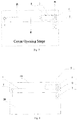
Fig. 1 is a schematic view of the cover opening/closing mechanism of the cooking appliance in a first preferred embodiment of the present disclosure; -
Fig. 2 is a schematic view of the cover opening/closing mechanism of the cooking appliance in a second preferred embodiment of the present disclosure; -
Fig. 3 is a schematic view of the cover opening/closing mechanism of the cooking appliance shown inFig. 2 in a cover opening prevention (cover self-locking) stage; -
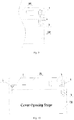
Fig. 4 is a schematic view of the cover opening/closing mechanism of the cooking appliance shown inFig. 2 in a cover opening stage; -
Fig. 5 is a schematic structural diagram of the cooking appliance shown inFig. 2 after the cover is opened; -
Fig. 6 is a schematic diagram of the cover opening/closing mechanism of the cooking appliance in a third preferred embodiment of the present disclosure, showing the moment analysis of the cover opening/closing mechanism in the cover opening prevention stage; -
Fig. 7 shows the moment analysis of the cover opening/closing mechanism of the cooking appliance shown inFig. 6 in the cover opening stage; -
Fig. 8 is a schematic view of the cover opening/closing mechanism of the cooking appliance in a fourth preferred embodiment of the present disclosure; -
Fig. 9 is a partially enlarged view of the attractive closing assembly inFig. 8 ; -
Fig. 10 is a schematic structural diagram of the cooking appliance shown inFig. 8 in the cover opening stage; -
Fig. 11 is a partially enlarged view of the attractive closing assembly inFig. 10 ; -
Fig. 12 is a schematic structural diagram of the cooking appliance shown inFig. 8 after the cover is opened; -
Figs. 13-15 are schematic diagrams of the cover opening/closing mechanism of the cooking appliance in a fifth preferred embodiment of the present disclosure, showing the processes before the magnetic isolation button is pressed, after the magnetic isolation button is pressed, and after the cover is opened; -
Fig. 16 shows various feasible arrangement positions of the attractive closing assembly in an electric cooker; and -
Fig. 17 is a schematic circuit diagram of an exemplary current reversing switch. - Hereunder some embodiments of the present disclosure will be detailed with reference to the accompanying drawings. It should be understood that the embodiments described here are only provided to describe and explain the present disclosure rather than constitute any limitation to the present disclosure.
- In the present disclosure, unless otherwise specified, the words that denote directions or orientations, such as "above", "below", "top", and "bottom", etc., are usually used to describe the relative position relations among the components with respect to the direction shown in the accompanying drawings or the vertical, plumb, or gravity direction.
- The present disclosure provides a novel cooking appliance. As shown in
Fig. 1 , the cooking appliance comprises abase 200 and acover body 100, thecover body 100 pivotally mounted on the base 200 in an openable/closable manner, wherein a pivot spring 1 (e.g., torsion spring, etc.) sleeved on apivot shaft 2 is provided at a pivotally connecting portion between the base 200 and thecover body 100, and the distal ends of thebase 200 and thecover body 100 with respect to the pivotally connecting portion are provided with an attractive closing assembly for opening/closing a cover. The attractive closing assembly for controlling cover opening/closing may comprise a first attractive closing member and a second attractive closing member, one of which is provided on thebase 200 and the other is provided on thecover body 100, and the first attractive closing member and the second attractive closing member attract each other to lock thecover body 100 on thebase 200. Such an attractive closing assembly may achieve attractive closing in a variety of ways, such as vacuum suction closing, or magnetically attractive locking as detailed below, etc. - Apparently, an attractive closing assembly is employed in the product provided by the present disclosure in replacement of the traditional mechanical snap-fit locking structure. The attractive closing assembly does not require structural fitting or direct contact, has low requirements for manufacturing accuracy, assembling shape and position accuracy and the like, and even is not limited to an exposed form, which is to say, the attractive closing assembly may be designed into a concealed form, i.e., may be concealed in the main body of the product, without affecting the appearance of the product at all.
- In an embodiment shown in
Fig. 1 , magnetically attractive closing can be realized simply by mountingmagnets 3 on the respective distal ends of thecover body 100 and the base 20, wherein both the first attractive closing member (or first magnetic attraction member) and the second attractive closing member (or second magnetic attraction member) aremagnets 3. When the cover is closed, self-locking of the cover body can be realized by virtue of the magnetic attraction force between themagnets 3. The cover may be opened manually when required. - The
magnets 3 are not limited to permanent magnets, but alternatively may be electromagnets with adjustable magnetic attraction force, or the like. As shown inFig. 2 , the attractive closing assembly in another embodiment comprises amagnet 3 serving as the first attractive closing member and an electromagnet circuit with aniron core rod 4 serving as the second attractive closing member. One of themagnet 3 and the electromagnet circuit is disposed on the distal end of thebase 200 and the other of themagnet 3 and the electromagnet circuit is disposed on the distal end of thecover body 100, and themagnet 3 locks thecover body 100 by magnetically attracting theiron core rod 4. Wherein magnetic attraction force exists between theiron core rod 4 itself and themagnet 3. After the electromagnet is formed by energization, the magnetic attraction force can be increased, but magnetic repulsion force may be created alternatively. In that way, the cover may be automatically opened/closed by means of the electromagnet circuit further. For example, in the cover opening prevention stage as shown inFig. 3 , since self-locking of the cover body is required, enhanced magnetic attraction force, i.e., Fa indicated by the arrow in the figure, is generated between the electromagnet and the magnet. In the cover opening stage as shown inFig. 4 , the polarity of the electromagnet is reversed so that magnetic repulsion force Fb is generated between the electromagnet and the magnet to automatically open the cover, as shown inFig. 5 . - As shown in
Fig. 2 , the electromagnet circuit is provided with acircuit switch 5 for controlling the energization of the electromagnet. When thecircuit switch 5 is pressed so that enhanced magnetic attraction force is generated between the electromagnet and the magnet, thecircuit switch 5 serves as a cover self-locking switch button. When thecircuit switch 5 is pressed so that enhanced magnetic repulsion force is generated between the electromagnet and the magnet, thecircuit switch 5 serves as a cover opening button. - Usually, the electromagnet circuit is electrically connected to the power supply of the cooking appliance, i.e., it is usually an AC electromagnet. Of course, the electromagnet circuit may also have its own power source, such as a power battery, to form a DC electromagnet. Those skilled in the art know well the fact that an AC electromagnet has a characteristic of relatively constant suction force, but may produce slight vibrations in the attraction process, and the winding coil of the electromagnet may be over-heated. A DC electromagnet doesn't produce any vibration and the winding coil is not subjected to overheat in the attraction process, but the attraction force of a DC electromagnet increases gradually. Therefore, the energization modes of the electromagnets have their respective advantages and disadvantages. The specific electromagnets to be used should be designed specifically according to the product, and will not be detailed here anymore.
- When the electromagnet circuit is electrically connected to the power supply of the cooking appliance, the self-locking of the cover body is realized depending on the magnetic attraction force between the
magnet 3 and theiron core rod 4, and thecover body 100 may be opened manually, if the product is not energized. The self-locking can be further enhanced by the electromagnet, and thecover body 100 can be opened automatically by reversing the polarity of the electromagnet, if the product is energized. - Wherein, whether connected to AC power supply or DC power supply, the electromagnet circuit preferably comprises a current reversing switch for switching the current flowing through the electromagnet so as to reverse the polarity of the electromagnet timely during cover opening/closing, i.e. the current reversing switch enables the electromagnet to generate magnetic repulsion force against the
magnet 3 to open thecover body 100 or switch to generate magnetic attraction force with respect to themagnet 3 so as to achieve self-locking of thecover body 100. Such a current reversing switch may be implemented by means of a program setting of the power supply control unit or a simple bridge switch circuit. As shown inFig. 17 , in an example, twogang switches 9 form a current reversing switch, and may work in combination with a bridge circuit to realize the current reversing for the electromagnet. Therefore, the current reversing switch may be embodied as a physical switch or a virtual button displayed on a display screen, etc., which are common general knowledge known to those skilled in the art and will not be detailed here. - Particularly, the magnitude of the current in the electromagnet circuit may be altered, in order to further realize gradual adjustment of the magnitude of the magnetic attraction force or magnetic repulsion force and facilitate self-locking or automatic cover opening. Similarly, those skilled in the art can understand that such current magnitude adjustment may be implemented by means of a variety of simple external circuits or controlled by a controller. In a specific embodiment of the present disclosure, as shown in
Figs. 6 and7 , the electromagnet circuit comprises a slide rheostat 8 with a slide switch connected in shunt with the electromagnet. Thus, thecover body 100 may be locked or opened by shifting the slide switch to alter the magnetic attraction force between the electromagnet and themagnet 3. In that way, the slide rheostat 8 may be utilized to realize gradual adjustment control of the electromagnetic attraction force by altering the current. - As shown in
Figs. 8-12 , in another preferred embodiment of the present disclosure, theiron core rod 4 is preferably a telescopically movable rod that can move between a proximal position and a distal position with respect to themagnet 3. In the closed state of thecover body 100, the magnetic attraction force between theiron core rod 4 and themagnet 3 is relatively high at the proximal position and thecover body 100 is kept in the closed state; the magnetic attraction force between theiron core rod 4 and themagnet 3 is weakened at the distal position and thecover body 100 can be pivotally opened automatically to the open state shown inFig. 12 . Thus, automatic cover locking and opening can be achieved excellently by designing the parameters of theiron core rod 4, such as the moving stroke and spacing, etc. - Specifically, at the proximal position shown in
Figs. 8 and9 , the minimum spacing between theiron core rod 4 and themagnet 3 is a. With respect to the pivot hinge point between thecover body 100 and thebase 200, the sum of the attractive closing torque of the magnetic attraction force between themagnet 3 and theiron core rod 4 and the gravity center torque of thecover body 100 should be greater than the return torque of thepivot spring 1 in order to realize the closing of the cover body; at the distal position shown inFigs. 10 and11 , the minimum spacing between theiron core rod 4 and themagnet 3 is increased to b, and the sum of the attractive closing torque of the magnetic attraction force between themagnet 3 and theiron core rod 4 and the gravity center torque of thecover body 100 should be smaller than the return torque of thepivot spring 1 in order to open thecover body 100 automatically. After thecover body 100 is opened, as shown inFig. 12 , theiron core rod 4 therein is reset to the iron core rod position shown inFigs. 8 and9 . - In order to realize the cooperative movement of the
iron core rod 4 for opening or closing the cover, in an embodiment, the cooking appliance may comprise a shift lever mechanism (not shown in the figures) with a shift lever switch. When the shift lever switch is triggered, the shift lever mechanism shifts theiron core rod 4 from the proximal position to the distal position, i.e. moves theiron core rod 4 away from themagnet 3 under external force. In that way, the shift lever switch is configured as a cover opening button. Usually, theiron core rod 4 is disposed in thecover body 100, as shown inFig. 8 . In that case, the shift lever switch may also be disposed accordingly on the face cover of thecover body 100 to facilitate the user to press and operate. - The aforesaid
iron core rod 4 may be a separate iron rod or iron block. Furthermore, the attractive closing assembly may comprise an electromagnet circuit provided with an electromagnet. As shown inFig. 9 , the electromagnet comprises aniron core rod 4 and a conductive winding wound around theiron core rod 4. In that case, theiron core rod 4 is an induction iron core of the electromagnet. In an energized state of the electromagnet, theiron core rod 4 can move away from themagnet 3 automatically under the magnetic attraction force, and the electromagnet is turned into the state shown inFig. 11 from the state shown inFig. 9 . Here, the electromagnet circuit comprises acircuit switch 5 serving as an iron core rod movement control valve. In the ON state of thecircuit switch 5, theiron core rod 4 moves from the proximal position to the distal position so that it is further inserted into the conductive winding. Furthermore, in the ON state of thecircuit switch 5, the electromagnet can be configured to generate magnetic repulsion force against themagnet 3, which is more favorable for opening thecover body 100. Wherein preferably the proximal end of theiron core rod 4 with respect to themagnet 3 is formed as abig end 41 to facilitate magnetic attraction. - In another preferred embodiment of the present disclosure as shown in
Figs. 13-15 , a magnetic isolation assembly is additionally provided. The magnetic isolation assembly comprises a movablemagnetic isolation plate 6, which can be pushed into a space between an upper magnetic attraction body and a lower magnetic attraction body or moved out of the space, so as to control to open or close thecover body 100 accordingly. Compared with the electromagnet polarity reversing scheme described above, the cover opening/closing control scheme utilizing the magnetic isolation assembly has advantages including lower cost and simpler and more convenient operation. - Wherein the function of the magnetic isolation assembly is to controllably extend into the space between the upper magnetic attraction body and the lower magnetic attraction body (i.e. between the first attractive closing member and the second attractive closing member) to block or reduce the magnetic attraction force between them, and thereby attains the object of cover opening control. Specifically, as shown in
Fig. 13 , the magnetic isolation assembly comprises amagnetic isolation button 7 with a return spring, and themagnetic isolation button 7 is connected with amagnetic isolation plate 6 and can drive themagnetic isolation plate 6 to extend into the space between the upper magnetic attraction body and the lower magnetic attraction body to inhibit magnetic attraction when the button is pressed. After thecover body 100 is opened, as shown inFig. 15 , themagnetic isolation button 7 can be released, and then themagnetic isolation button 7 is smoothly returned by the return spring to the state before it is pressed. - Wherein the
magnetic isolation plate 6 may be in a plate shape and inserted between the upper magnetic attraction body and the lower magnetic attraction body. However, in order to attain a better magnetic isolation effect, the illustratedmagnetic isolation plate 6 is preferably formed into a frame structure with an open end, and the upper magnetic attraction body or the lower magnetic attraction body is fully framed inside the frame structure when themagnetic isolation button 7 is in the pressed state. - The
magnetic isolation plate 6 may be made of any material capable of isolating or suppressing magnetism, which usually may be selected from aluminum sheet, aluminum alloy sheet, stainless steel sheet, or copper sheet, etc. - In view that the
cover body 100 has to be opened pivotally, themagnetic isolation button 7 serving as a cover opening button is preferably disposed on thebase 200, as shown inFigs. 13 and 14 , so as to prevent touching the cover body and avoid hand scalding by the high-temperature vapor when the cover is opened. - It should be noted that the upper magnetic attraction body and the lower magnetic attraction body shown in
Figs. 13-15 magnetically attract each other in the closed state of the cover body. Both of the upper magnetic attraction body and the lower magnetic attraction body may be permanent magnets, or either the upper magnetic attraction body or the lower magnetic attraction body is a permanent magnet, while the other is an iron block. Moreover, either the upper magnetic attraction body or the lower magnetic attraction body may be an electromagnet, such as an AC electromagnet connected to AC power supply. The electromagnet circuit of the electromagnet preferably is provided with acircuit switch 5 for controlling the energization of theelectromagnet 5. - It should be noted that the
circuit switch 5, the current reversing switch, the slide switch of the slide rheostat 8, and themagnetic isolation button 7, etc. may be used separately as a cover opening switch or used in combination to form a combined cover opening button switch. - The aforesaid attractive closing assembly may be applied to various types of cooking appliances, especially electric cookers, for controlling the opening, closing and locking of the cover body from/to the cooker body. In practical applications, most of the electric cookers available on the market are in a rectangular shape. As shown in
Fig. 16 , the rectangular profile of an electric cooker comprises a first edge of rectangle, a second edge of rectangle, a third edge of rectangle, and a fourth edge of rectangle, which are connected sequentially. The pivot hinge point between thecover body 100 and thebase 200 is formed at the midpoint position of the first edge of rectangle, i.e., the pivot hinge point OO' in the figure, and the attractive closing assembly may be arranged at the midpoint position of the third edge of rectangle and/or the attractive closing assembly may be arranged at a symmetrical position of the second edge of rectangle and the fourth edge of rectangle, e.g., the attractive closing assembly arrangement position P1, P2, P3, P4, or P5 in the figure. - Various specific embodiments of the attractive closing assembly for food cooking are described above. In practical applications, the design of the structural parameters should be specifically determined according to the requirements for cover opening/closing.
- As shown in
Fig. 6 , in the closed state of thecover body 100, the return torque M2 of thepivot spring 1 is smaller than the sum of the attractive closing torque M3 of the magnetic attraction force between themagnet 3 and theiron core rod 4 and the gravity center torque M1 of thecover body 100 with respect to the pivot hinge point (i.e., the pivot hinge point OO' shown inFig. 16 ) between thecover body 100 and thebase 200. In that way, the cover locking moment can be greater than the cover opening moment in the cover opening prevention stage, and self-locking of the cover body can be realized. - Specifically, in various embodiments, when the electromagnet is not energized, the magnetic attraction force between the
magnet 3 and theiron core rod 4 is relatively small, but should be enough for self-locking of the cover body. In order to ensure the safety and reliability of the self-locking of the cover body, it is necessary to reserve a margin for the cover locking moment, for example, a condition M3-(M2-M1)>1Nm should be met, so that the cover body can be opened automatically under the internal pressure of the cooking appliance. - In the case that an electromagnet circuit is provided, the conductive winding wound around the
iron core rod 4 enhances the magnetic attraction force, and the conductive electromagnet enhances the self-locking performance of the cover body, which is more in line with the margin design of the cover locking moment. However, in order to improve the magnetic induction efficiency, preferably a condition M3-(M2-M1)<15Nm is met in the energized state of the electromagnet, which is helpful for reducing the power consumption of the product and prolong the service life of the electric components. - As shown in
Fig. 7 , in a cover opening stage in which the cover in the closed state is to be opened, the flow direction of the current flowing through the electromagnet may be reversed by means of the current reversing switch, so that the electromagnet generates magnetic repulsion force against themagnet 3 to open thecover body 100. Under that condition, when thecover body 100 is in the closed state and the electromagnet is energized, the sum of the magnetic repulsion torque M4 of the magnetic repulsion force between themagnet 3 and the electromagnet and the return torque M2 of thepivot spring 1 is greater than the gravity center torque M1 of thecover body 100 with respect to the pivot hinge point, i.e., the upward torque is greater than the downward torque inFig. 7 , and thecover body 100 can be opened. - Likewise, in order to ensure the reliability of cover opening, a margin should be design for the cover opening torque, for example, a condition M4+M2-M1>1Nm should be met, to prevent the cover body from opening automatically owing to accident vibration, impact or internal pressure, etc. Based on the above torque analysis, appropriate torsion springs and magnets, etc., may be selected purposefully according to the design parameters to achieve cover opening/closing control that meets the design requirements.
- In summary, the present disclosure designs a novel magnetically attractive locking mechanism for cover opening/closing, which may be applied to products such as electric cookers and the like. By means of the magnet attraction between the upper magnet and the lower magnet, cover self-locking can be achieved by closing and locking the cover under the magnet attraction force when the cover shouldn't be opened in some operation procedures (e.g., in a rice washing process). When required, the cover may be opened safely, for example, simply by pressing a button in the traditional way to reduce the magnetic attraction force quickly, without increasing the product cost too much. In addition, the cover opening/closing mechanism may be concealed in the cover body and the base, without affecting the appearance of the product at all.
- While some preferred embodiments of the present disclosure are described above with reference to the accompanying drawings, the present disclosure is not limited to the details in those embodiments. Those skilled in the art can make modifications and variations to the technical scheme of the present disclosure, without departing from the spirit of the present disclosure. For example, the portion of the magnetically attractive locking mechanism located in the cover body may be interchanged with the portion located in the base; it is not mandatory to arrange both of the electromagnets on the cover body as shown in the figures; alternatively the electromagnets may be arranged on the base, or even the magnets on the cover body and the base may be electromagnets. The control of the magnitude of the current flowing through the electromagnets is not limited to control with a slide rheostat; instead, current of appropriate magnitude may be fed from an external current supply unit, etc. Such simple modifications and variations shall be deemed as falling in the scope of protection of the present disclosure.
- In addition, it should be noted that the specific technical features described in above specific embodiments may be combined in any appropriate form, provided that there is no conflict among them. To avoid unnecessary repetition, various possible combinations are not described specifically in the present disclosure.
- Moreover, different embodiments of the present disclosure may also be combined freely as required, as long as the combinations don't deviate from the ideal and spirit of the present disclosure. However, such combinations shall also be deemed as falling into the scope disclosed in the present disclosure.
| 1 | | 2 | |
| 3 | | 4 | Iron Core |
| 5 | | 6 | |
| 7 | Magnetic Isolation Button | 8 | |
| 9 | | ||
| 41 | Big End | OO' | Pivot Hinge |
| 100 | | 200 | Base |
| P1∼P5 Attractive Closing Assembly Arrangement Position | |||
Claims (21)
- A cooking appliance, comprising a base (200) and a cover body (100) pivotally mounted on the base (200) in an openable/closable manner, wherein the cooking appliance further comprises:a pivot spring (1) provided at a pivotal connecting portion between the base (200) and the cover body (100); andan attractive closing assembly comprising a first attractive closing member and a second attractive closing member, wherein one of the first attractive closing member and the second attractive closing member is provided on the base (200), the other of the first attractive closing member and the second attractive closing member is provided on the cover body (100), and the first attractive closing member and the second attractive closing member attract each other to lock the cover body (100) on the base (200).
- The cooking appliance of claim 1, wherein in a closed state of the cover body (100), with respect to a pivot hinge point between the cover body (100) and the base (200), a return torque M2 of the pivot spring (1) is smaller than a sum of an attractive closing torque M3 of a magnetic attraction force between the first attractive closing member and the second attractive closing member and a gravitational torque M1 of the cover body (100)
- The cooking appliance of claim 2, wherein M3-(M2-M1)>1N·m and M3-(M2-M1) <15N.m.
- The cooking appliance of claim 1, wherein the attractive closing assembly is a magnetically attractive locking assembly provided on a distal end with respect to the pivotal connecting portion.
- The cooking appliance of claim 4, wherein the magnetically attractive locking assembly comprises a magnet (3) serving as the first attractive closing member and an iron core rod (4) serving as the second attractive closing member.
- The cooking appliance of claim 5, further comprising a shift lever mechanism having a shift lever switch, wherein the shift lever mechanism shifts the iron core rod (4) from a proximal position toward a distal position when the shift lever switch is triggered.
- The cooking appliance of claim 5, wherein the iron core rod (4) is a telescopically movable rod capable of moving between a proximal position and a distal position with respect to the magnet (3) in the closed state of the cover body (100);
wherein at the proximal position, with respect to the pivot hinge point between the cover body (100) and the base (200), the sum of the attractive closing torque M3 of the magnetic attraction force between the magnet (3) and the iron core rod (4) and the gravitational torque M1 of the cover body (100) is greater than the return torque M2 of the pivot spring (1), so as to lock the cover body (100);
at the distal position, the sum of the attractive closing torque M3 of the magnetic attraction force between the magnet (3) and the iron core rod (4) and the gravitational torque M1 of the cover body (100) is smaller than the return torque M2 of the pivot spring (1), so as to open the cover body (100). - The cooking appliance of claim 5, comprising an electromagnet circuit having an electromagnet, the electromagnet comprises the iron core rod (4) and a conductive winding wound around the iron core rod (4).
- The cooking appliance of claim 8, wherein the electromagnet circuit is provided with a circuit switch (5) for controlling an energization of the electromagnet.
- The cooking appliance of claim 9, wherein in an ON state of the circuit switch (5), the iron core rod (4) moves from the proximal position toward the distal position so that it is further inserted into the conductive winding of the electromagnet.
- The cooking appliance of claim 10, wherein the end of the iron core rod (4) proximal to the magnet (3) is formed as a big end (41).
- The cooking appliance of claim 8, wherein the electromagnet circuit comprises a current reversing switch, which is configured to switch the flow direction of the current flowing through the electromagnet, and enables the electromagnet to generate magnetic repulsion force with respect to the magnet (3) to open the cover body (100), or to generate magnetic attraction force with respect to the magnet (3) to achieve self-locking of the cover body (100).
- The cooking appliance of claim 12, wherein when the cover body (100) is in the closed state and the electromagnet is in an energized state, with respect to the pivot hinge point, the sum of a magnetic repulsion torque M4 of a magnetic repulsion force between the magnet (3) and the electromagnet and the return torque M2 of the pivot spring (1) is greater than the gravitational torque M1 of the cover body (100), wherein M4+M2-M1>1N·m.
- The cooking appliance of claim 8, wherein the electromagnet is an AC electromagnet.
- The cooking appliance according to any of claims 8-14, wherein the electromagnet circuit is provided with a slide rheostat (8) having a slide switch, and the cover body (100) can be locked or opened by shifting the slide switch to change the magnetic attraction force between the electromagnet and the magnet (3).
- The cooking appliance of claim 5, wherein the magnet (3) is an electromagnet.
- The cooking appliance of claim 4, wherein the magnetically attractive locking assembly comprises a first magnetic attraction member and a second magnetic attraction member, and the cooking appliance further comprises a magnetic isolation assembly comprising a magnetic isolation plate (6) made of a magnetic isolation material and a magnetic isolation button (7) having a return spring, and the magnetic isolation button (7) is capable of driving the magnetic isolation plate (6) to extend into a space between the first magnetic attraction member and the second magnetic attraction member to inhibit magnetic attraction and to open the cover body (100) when the magnetic isolation button (7) is in a pressed state.
- The cooking appliance of claim 17, wherein the magnetic isolation plate (6) is formed into a frame structure with an open end, and the first magnetic attraction member or the second magnetic attraction member is framed inside the frame structure when the magnetic isolation button (7) is in the pressed state.
- The cooking appliance of claim 17, wherein the magnetic isolation assembly is provided in the base (200), and the magnetic isolation plate (6) is an aluminum alloy plate, a stainless steel plate or a copper plate.
- The cooking appliance of claim 1, wherein the cooking appliance is an electric cooker.
- The cooking appliance of claim 20, wherein the cover body (100) has a rectangular profile comprising a first edge of a rectangle, a second edge of the rectangle, a third edge of the rectangle and a fourth edge of the rectangle which are sequentially connected to each other, the pivot hinge point between the cover body (100) and the base (200) is formed at a midpoint position of the first edge of the rectangle, the attractive closing assembly is arranged at a midpoint position of the third edge of the rectangle and/or the attractive closing assembly is arranged at symmetrical positions with respect to the second edge of the rectangle and the fourth edge of the rectangle.
Applications Claiming Priority (7)
| Application Number | Priority Date | Filing Date | Title |
|---|---|---|---|
| CN201721861605.5U CN208822310U (en) | 2017-12-27 | 2017-12-27 | Cooking apparatus |
| CN201721885495.6U CN208822311U (en) | 2017-12-27 | 2017-12-27 | Cooking apparatus |
| CN201721886233.1U CN208822450U (en) | 2017-12-27 | 2017-12-27 | Cooking apparatus |
| CN201711448387.7A CN109965666B (en) | 2017-12-27 | 2017-12-27 | Cooking utensil |
| CN201721885605.9U CN208822312U (en) | 2017-12-27 | 2017-12-27 | Cooking apparatus |
| CN201711446836.4A CN109965665B (en) | 2017-12-27 | 2017-12-27 | Cooking utensil |
| PCT/CN2018/090427 WO2019128117A1 (en) | 2017-12-27 | 2018-06-08 | Cooking appliance |
Publications (3)
| Publication Number | Publication Date |
|---|---|
| EP3705001A1 true EP3705001A1 (en) | 2020-09-09 |
| EP3705001A4 EP3705001A4 (en) | 2021-01-20 |
| EP3705001B1 EP3705001B1 (en) | 2024-11-06 |
Family
ID=67065014
Family Applications (1)
| Application Number | Title | Priority Date | Filing Date |
|---|---|---|---|
| EP18897618.7A Active EP3705001B1 (en) | 2017-12-27 | 2018-06-08 | Cooking appliance |
Country Status (5)
| Country | Link |
|---|---|
| US (1) | US11653788B2 (en) |
| EP (1) | EP3705001B1 (en) |
| JP (1) | JP7027550B2 (en) |
| KR (1) | KR102350545B1 (en) |
| WO (1) | WO2019128117A1 (en) |
Cited By (1)
| Publication number | Priority date | Publication date | Assignee | Title |
|---|---|---|---|---|
| CN108261057A (en) * | 2016-12-30 | 2018-07-10 | 浙江绍兴苏泊尔生活电器有限公司 | Cooking utensil |
Families Citing this family (4)
| Publication number | Priority date | Publication date | Assignee | Title |
|---|---|---|---|---|
| CN114503212B (en) * | 2019-10-10 | 2025-11-21 | 三星麦迪森株式会社 | Medical device and method for operating a medical device |
| US11435089B2 (en) * | 2020-09-02 | 2022-09-06 | Haier Us Appliance Solutions, Inc. | Retractable display for an oven appliance |
| JP2022182048A (en) * | 2021-05-27 | 2022-12-08 | タイガー魔法瓶株式会社 | container |
| KR102843432B1 (en) * | 2023-03-03 | 2025-08-12 | 베이시스푸드(주) | Ginseng processing method and ginseng processed thereby |
Family Cites Families (20)
| Publication number | Priority date | Publication date | Assignee | Title |
|---|---|---|---|---|
| JPS5520259Y2 (en) * | 1975-06-06 | 1980-05-15 | ||
| JPS5829016U (en) * | 1981-08-18 | 1983-02-25 | 三洋電機株式会社 | Square cylinder rice cooker lid device |
| CH658438A5 (en) | 1981-10-22 | 1986-11-14 | Saseb Ag | Closure for containers |
| JPH05198152A (en) * | 1992-01-21 | 1993-08-06 | Hitachi Ltd | Door opener |
| JP2000051085A (en) | 1998-08-06 | 2000-02-22 | Emi Nakayama | Heating cooking device |
| KR20010048286A (en) | 1999-11-26 | 2001-06-15 | 정담 | Lid opening and closing device of electric kettle |
| JP2005304522A (en) | 2004-04-16 | 2005-11-04 | Matsushita Electric Ind Co Ltd | rice cooker |
| JP4225557B2 (en) | 2005-11-18 | 2009-02-18 | 独立行政法人 宇宙航空研究開発機構 | Magnetic support balance device with a mechanism for removing equipment such as models |
| KR100871092B1 (en) | 2008-09-18 | 2008-11-28 | 주식회사 세신산업 | Double sided frying pan |
| JP5243342B2 (en) | 2009-05-12 | 2013-07-24 | 象印マホービン株式会社 | Electrical equipment with open / close lid |
| CN202619335U (en) | 2012-01-13 | 2012-12-26 | 浙江苏泊尔家电制造有限公司 | Electric rice cooker with magnetic switch |
| KR200462610Y1 (en) * | 2012-06-20 | 2012-09-19 | (주)잔티아시아 | Electronic cigarette with cartridges for leakage preventing and detachable combustion |
| CN102918965B (en) | 2012-07-31 | 2014-12-03 | 江苏大学 | Magnetic-type precise seed-metering device |
| CN203447061U (en) | 2013-05-22 | 2014-02-26 | 浙江苏泊尔家电制造有限公司 | Electric cooker |
| CN205568748U (en) | 2016-02-29 | 2016-09-14 | 九阳股份有限公司 | Electric heat pot that can automatic uncap |
| CN206560346U (en) | 2016-08-11 | 2017-10-17 | 中山市金美誉电器有限公司 | An automatic reversible rice cooker |
| CN106213976A (en) | 2016-08-28 | 2016-12-14 | 向双红 | A flip-top electric rice cooker |
| CN106175574A (en) | 2016-08-31 | 2016-12-07 | 洛阳圣瑞智能机器人有限公司 | The intelligent double-sided glass-cleaning robot of mixing and absorption |
| CN106678427B (en) | 2017-03-17 | 2022-11-18 | 泉州市纵能电磁阀有限公司 | Time-delay self-closing flushing valve |
| JP6578315B2 (en) * | 2017-04-19 | 2019-09-18 | アイリスオーヤマ株式会社 | rice cooker |
-
2018
- 2018-06-08 KR KR1020207018892A patent/KR102350545B1/en active Active
- 2018-06-08 US US16/766,781 patent/US11653788B2/en active Active
- 2018-06-08 EP EP18897618.7A patent/EP3705001B1/en active Active
- 2018-06-08 JP JP2020535585A patent/JP7027550B2/en active Active
- 2018-06-08 WO PCT/CN2018/090427 patent/WO2019128117A1/en not_active Ceased
Cited By (1)
| Publication number | Priority date | Publication date | Assignee | Title |
|---|---|---|---|---|
| CN108261057A (en) * | 2016-12-30 | 2018-07-10 | 浙江绍兴苏泊尔生活电器有限公司 | Cooking utensil |
Also Published As
| Publication number | Publication date |
|---|---|
| US11653788B2 (en) | 2023-05-23 |
| EP3705001B1 (en) | 2024-11-06 |
| KR102350545B1 (en) | 2022-01-14 |
| US20200315398A1 (en) | 2020-10-08 |
| KR20200089748A (en) | 2020-07-27 |
| WO2019128117A1 (en) | 2019-07-04 |
| JP2021508534A (en) | 2021-03-11 |
| EP3705001A4 (en) | 2021-01-20 |
| JP7027550B2 (en) | 2022-03-01 |
Similar Documents
| Publication | Publication Date | Title |
|---|---|---|
| EP3705001B1 (en) | Cooking appliance | |
| CN109965665B (en) | Cooking utensil | |
| US20130063231A1 (en) | Solenoid-actuated contactor | |
| CN104995347B (en) | Magnetically activated door-lock device | |
| CN218548253U (en) | Contactor self-locking device | |
| CN105054770B (en) | A kind of pressure regulating mechanism and the pressure cooker provided with the pressure regulating mechanism | |
| CN105011743B (en) | A kind of pressure regulating mechanism and it is provided with the pressure cooker of the pressure regulating mechanism | |
| CN109979783B (en) | A contactor | |
| JP2019096575A (en) | Vacuum circuit breaker | |
| CA2874724C (en) | Electrical switching apparatus and relay including a ferromagnetic or magnetic armature having a tapered portion | |
| CN204862630U (en) | Pressure adjustment mechanism and be equipped with this pressure adjustment mechanism's pressure cooker | |
| CN109965666B (en) | Cooking utensil | |
| CN104997391B (en) | A kind of pressure regulating mechanism and it is provided with the pressure cooker of the pressure regulating mechanism | |
| CN104997395B (en) | A kind of pressure regulating mechanism and the pressure cooker provided with the pressure regulating mechanism | |
| CN205107307U (en) | Pressure adjustment mechanism and be equipped with this pressure adjustment mechanism's pressure cooker | |
| CN205006638U (en) | Pressure adjustment mechanism and be equipped with this pressure adjustment mechanism's pressure cooker | |
| CN104997393B (en) | A kind of pressure regulating mechanism and the pressure cooker provided with the pressure regulating mechanism | |
| CN208822450U (en) | Cooking apparatus | |
| CN108573831B (en) | Low-Power AC-DC Expansion Module for AC Contactors | |
| CN204862636U (en) | Electric pressure cooker's canceling release mechanical system and electric pressure cooker | |
| CN105011744B (en) | A kind of pressure regulating mechanism and the pressure cooker provided with the pressure regulating mechanism | |
| CN205006637U (en) | Pressure adjustment mechanism and be equipped with this pressure adjustment mechanism's pressure cooker | |
| CN208822311U (en) | Cooking apparatus | |
| CN209249303U (en) | A rolling contact switch | |
| CN103400709B (en) | Small low voltage switch remote control operating mechanism |
Legal Events
| Date | Code | Title | Description |
|---|---|---|---|
| STAA | Information on the status of an ep patent application or granted ep patent |
Free format text: STATUS: THE INTERNATIONAL PUBLICATION HAS BEEN MADE |
|
| PUAI | Public reference made under article 153(3) epc to a published international application that has entered the european phase |
Free format text: ORIGINAL CODE: 0009012 |
|
| STAA | Information on the status of an ep patent application or granted ep patent |
Free format text: STATUS: REQUEST FOR EXAMINATION WAS MADE |
|
| 17P | Request for examination filed |
Effective date: 20200605 |
|
| AK | Designated contracting states |
Kind code of ref document: A1 Designated state(s): AL AT BE BG CH CY CZ DE DK EE ES FI FR GB GR HR HU IE IS IT LI LT LU LV MC MK MT NL NO PL PT RO RS SE SI SK SM TR |
|
| AX | Request for extension of the european patent |
Extension state: BA ME |
|
| A4 | Supplementary search report drawn up and despatched |
Effective date: 20201217 |
|
| RIC1 | Information provided on ipc code assigned before grant |
Ipc: A47J 36/10 20060101ALI20201211BHEP Ipc: A47J 27/00 20060101AFI20201211BHEP Ipc: A47J 27/08 20060101ALI20201211BHEP Ipc: A47J 36/00 20060101ALI20201211BHEP |
|
| DAV | Request for validation of the european patent (deleted) | ||
| DAX | Request for extension of the european patent (deleted) | ||
| STAA | Information on the status of an ep patent application or granted ep patent |
Free format text: STATUS: EXAMINATION IS IN PROGRESS |
|
| 17Q | First examination report despatched |
Effective date: 20230105 |
|
| GRAP | Despatch of communication of intention to grant a patent |
Free format text: ORIGINAL CODE: EPIDOSNIGR1 |
|
| STAA | Information on the status of an ep patent application or granted ep patent |
Free format text: STATUS: GRANT OF PATENT IS INTENDED |
|
| INTG | Intention to grant announced |
Effective date: 20240813 |
|
| GRAS | Grant fee paid |
Free format text: ORIGINAL CODE: EPIDOSNIGR3 |
|
| GRAA | (expected) grant |
Free format text: ORIGINAL CODE: 0009210 |
|
| STAA | Information on the status of an ep patent application or granted ep patent |
Free format text: STATUS: THE PATENT HAS BEEN GRANTED |
|
| AK | Designated contracting states |
Kind code of ref document: B1 Designated state(s): AL AT BE BG CH CY CZ DE DK EE ES FI FR GB GR HR HU IE IS IT LI LT LU LV MC MK MT NL NO PL PT RO RS SE SI SK SM TR |
|
| REG | Reference to a national code |
Ref country code: GB Ref legal event code: FG4D |
|
| REG | Reference to a national code |
Ref country code: CH Ref legal event code: EP |
|
| REG | Reference to a national code |
Ref country code: DE Ref legal event code: R096 Ref document number: 602018076413 Country of ref document: DE |
|
| REG | Reference to a national code |
Ref country code: IE Ref legal event code: FG4D |
|
| REG | Reference to a national code |
Ref country code: LT Ref legal event code: MG9D |
|
| REG | Reference to a national code |
Ref country code: NL Ref legal event code: MP Effective date: 20241106 |
|
| PG25 | Lapsed in a contracting state [announced via postgrant information from national office to epo] |
Ref country code: HR Free format text: LAPSE BECAUSE OF FAILURE TO SUBMIT A TRANSLATION OF THE DESCRIPTION OR TO PAY THE FEE WITHIN THE PRESCRIBED TIME-LIMIT Effective date: 20241106 Ref country code: PT Free format text: LAPSE BECAUSE OF FAILURE TO SUBMIT A TRANSLATION OF THE DESCRIPTION OR TO PAY THE FEE WITHIN THE PRESCRIBED TIME-LIMIT Effective date: 20250306 Ref country code: IS Free format text: LAPSE BECAUSE OF FAILURE TO SUBMIT A TRANSLATION OF THE DESCRIPTION OR TO PAY THE FEE WITHIN THE PRESCRIBED TIME-LIMIT Effective date: 20250306 |
|
| PG25 | Lapsed in a contracting state [announced via postgrant information from national office to epo] |
Ref country code: FI Free format text: LAPSE BECAUSE OF FAILURE TO SUBMIT A TRANSLATION OF THE DESCRIPTION OR TO PAY THE FEE WITHIN THE PRESCRIBED TIME-LIMIT Effective date: 20241106 Ref country code: NL Free format text: LAPSE BECAUSE OF FAILURE TO SUBMIT A TRANSLATION OF THE DESCRIPTION OR TO PAY THE FEE WITHIN THE PRESCRIBED TIME-LIMIT Effective date: 20241106 |
|
| REG | Reference to a national code |
Ref country code: AT Ref legal event code: MK05 Ref document number: 1738395 Country of ref document: AT Kind code of ref document: T Effective date: 20241106 |
|
| PG25 | Lapsed in a contracting state [announced via postgrant information from national office to epo] |
Ref country code: BG Free format text: LAPSE BECAUSE OF FAILURE TO SUBMIT A TRANSLATION OF THE DESCRIPTION OR TO PAY THE FEE WITHIN THE PRESCRIBED TIME-LIMIT Effective date: 20241106 |
|
| PG25 | Lapsed in a contracting state [announced via postgrant information from national office to epo] |
Ref country code: ES Free format text: LAPSE BECAUSE OF FAILURE TO SUBMIT A TRANSLATION OF THE DESCRIPTION OR TO PAY THE FEE WITHIN THE PRESCRIBED TIME-LIMIT Effective date: 20241106 |
|
| PG25 | Lapsed in a contracting state [announced via postgrant information from national office to epo] |
Ref country code: NO Free format text: LAPSE BECAUSE OF FAILURE TO SUBMIT A TRANSLATION OF THE DESCRIPTION OR TO PAY THE FEE WITHIN THE PRESCRIBED TIME-LIMIT Effective date: 20250206 |
|
| PG25 | Lapsed in a contracting state [announced via postgrant information from national office to epo] |
Ref country code: AT Free format text: LAPSE BECAUSE OF FAILURE TO SUBMIT A TRANSLATION OF THE DESCRIPTION OR TO PAY THE FEE WITHIN THE PRESCRIBED TIME-LIMIT Effective date: 20241106 Ref country code: LV Free format text: LAPSE BECAUSE OF FAILURE TO SUBMIT A TRANSLATION OF THE DESCRIPTION OR TO PAY THE FEE WITHIN THE PRESCRIBED TIME-LIMIT Effective date: 20241106 Ref country code: GR Free format text: LAPSE BECAUSE OF FAILURE TO SUBMIT A TRANSLATION OF THE DESCRIPTION OR TO PAY THE FEE WITHIN THE PRESCRIBED TIME-LIMIT Effective date: 20250207 |
|
| PG25 | Lapsed in a contracting state [announced via postgrant information from national office to epo] |
Ref country code: PL Free format text: LAPSE BECAUSE OF FAILURE TO SUBMIT A TRANSLATION OF THE DESCRIPTION OR TO PAY THE FEE WITHIN THE PRESCRIBED TIME-LIMIT Effective date: 20241106 |
|
| PG25 | Lapsed in a contracting state [announced via postgrant information from national office to epo] |
Ref country code: RS Free format text: LAPSE BECAUSE OF FAILURE TO SUBMIT A TRANSLATION OF THE DESCRIPTION OR TO PAY THE FEE WITHIN THE PRESCRIBED TIME-LIMIT Effective date: 20250206 |
|
| PG25 | Lapsed in a contracting state [announced via postgrant information from national office to epo] |
Ref country code: SM Free format text: LAPSE BECAUSE OF FAILURE TO SUBMIT A TRANSLATION OF THE DESCRIPTION OR TO PAY THE FEE WITHIN THE PRESCRIBED TIME-LIMIT Effective date: 20241106 |
|
| PGFP | Annual fee paid to national office [announced via postgrant information from national office to epo] |
Ref country code: DE Payment date: 20250625 Year of fee payment: 8 |
|
| PG25 | Lapsed in a contracting state [announced via postgrant information from national office to epo] |
Ref country code: DK Free format text: LAPSE BECAUSE OF FAILURE TO SUBMIT A TRANSLATION OF THE DESCRIPTION OR TO PAY THE FEE WITHIN THE PRESCRIBED TIME-LIMIT Effective date: 20241106 |
|
| PGFP | Annual fee paid to national office [announced via postgrant information from national office to epo] |
Ref country code: GB Payment date: 20250620 Year of fee payment: 8 |
|
| PG25 | Lapsed in a contracting state [announced via postgrant information from national office to epo] |
Ref country code: EE Free format text: LAPSE BECAUSE OF FAILURE TO SUBMIT A TRANSLATION OF THE DESCRIPTION OR TO PAY THE FEE WITHIN THE PRESCRIBED TIME-LIMIT Effective date: 20241106 |
|
| PGFP | Annual fee paid to national office [announced via postgrant information from national office to epo] |
Ref country code: FR Payment date: 20250620 Year of fee payment: 8 |
|
| PG25 | Lapsed in a contracting state [announced via postgrant information from national office to epo] |
Ref country code: RO Free format text: LAPSE BECAUSE OF FAILURE TO SUBMIT A TRANSLATION OF THE DESCRIPTION OR TO PAY THE FEE WITHIN THE PRESCRIBED TIME-LIMIT Effective date: 20241106 |
|
| PG25 | Lapsed in a contracting state [announced via postgrant information from national office to epo] |
Ref country code: SK Free format text: LAPSE BECAUSE OF FAILURE TO SUBMIT A TRANSLATION OF THE DESCRIPTION OR TO PAY THE FEE WITHIN THE PRESCRIBED TIME-LIMIT Effective date: 20241106 |
|
| PG25 | Lapsed in a contracting state [announced via postgrant information from national office to epo] |
Ref country code: CZ Free format text: LAPSE BECAUSE OF FAILURE TO SUBMIT A TRANSLATION OF THE DESCRIPTION OR TO PAY THE FEE WITHIN THE PRESCRIBED TIME-LIMIT Effective date: 20241106 |
|
| PG25 | Lapsed in a contracting state [announced via postgrant information from national office to epo] |
Ref country code: IT Free format text: LAPSE BECAUSE OF FAILURE TO SUBMIT A TRANSLATION OF THE DESCRIPTION OR TO PAY THE FEE WITHIN THE PRESCRIBED TIME-LIMIT Effective date: 20241106 |
|
| REG | Reference to a national code |
Ref country code: DE Ref legal event code: R097 Ref document number: 602018076413 Country of ref document: DE |
|
| PG25 | Lapsed in a contracting state [announced via postgrant information from national office to epo] |
Ref country code: SE Free format text: LAPSE BECAUSE OF FAILURE TO SUBMIT A TRANSLATION OF THE DESCRIPTION OR TO PAY THE FEE WITHIN THE PRESCRIBED TIME-LIMIT Effective date: 20241106 |
|
| PLBE | No opposition filed within time limit |
Free format text: ORIGINAL CODE: 0009261 |
|
| STAA | Information on the status of an ep patent application or granted ep patent |
Free format text: STATUS: NO OPPOSITION FILED WITHIN TIME LIMIT |
|
| 26N | No opposition filed |
Effective date: 20250807 |
|
| REG | Reference to a national code |
Ref country code: CH Ref legal event code: H13 Free format text: ST27 STATUS EVENT CODE: U-0-0-H10-H13 (AS PROVIDED BY THE NATIONAL OFFICE) Effective date: 20260127 |
|
| PG25 | Lapsed in a contracting state [announced via postgrant information from national office to epo] |
Ref country code: MC Free format text: LAPSE BECAUSE OF FAILURE TO SUBMIT A TRANSLATION OF THE DESCRIPTION OR TO PAY THE FEE WITHIN THE PRESCRIBED TIME-LIMIT Effective date: 20241106 |
|
| PG25 | Lapsed in a contracting state [announced via postgrant information from national office to epo] |
Ref country code: LU Free format text: LAPSE BECAUSE OF NON-PAYMENT OF DUE FEES Effective date: 20250608 |
|
| REG | Reference to a national code |
Ref country code: BE Ref legal event code: MM Effective date: 20250630 |
|
| PG25 | Lapsed in a contracting state [announced via postgrant information from national office to epo] |
Ref country code: IE Free format text: LAPSE BECAUSE OF NON-PAYMENT OF DUE FEES Effective date: 20250608 |
|
| PG25 | Lapsed in a contracting state [announced via postgrant information from national office to epo] |
Ref country code: BE Free format text: LAPSE BECAUSE OF NON-PAYMENT OF DUE FEES Effective date: 20250630 |
|
| PG25 | Lapsed in a contracting state [announced via postgrant information from national office to epo] |
Ref country code: CH Free format text: LAPSE BECAUSE OF NON-PAYMENT OF DUE FEES Effective date: 20250630 |