EP3704936A1 - A quick-release connector - Google Patents
A quick-release connector Download PDFInfo
- Publication number
- EP3704936A1 EP3704936A1 EP20158904.1A EP20158904A EP3704936A1 EP 3704936 A1 EP3704936 A1 EP 3704936A1 EP 20158904 A EP20158904 A EP 20158904A EP 3704936 A1 EP3704936 A1 EP 3704936A1
- Authority
- EP
- European Patent Office
- Prior art keywords
- quick
- pod
- insert
- release connector
- connector according
- Prior art date
- Legal status (The legal status is an assumption and is not a legal conclusion. Google has not performed a legal analysis and makes no representation as to the accuracy of the status listed.)
- Granted
Links
Images


Classifications
-
- A—HUMAN NECESSITIES
- A01—AGRICULTURE; FORESTRY; ANIMAL HUSBANDRY; HUNTING; TRAPPING; FISHING
- A01K—ANIMAL HUSBANDRY; AVICULTURE; APICULTURE; PISCICULTURE; FISHING; REARING OR BREEDING ANIMALS, NOT OTHERWISE PROVIDED FOR; NEW BREEDS OF ANIMALS
- A01K77/00—Landing-nets for fishing; Landing-spoons for fishing
-
- A—HUMAN NECESSITIES
- A01—AGRICULTURE; FORESTRY; ANIMAL HUSBANDRY; HUNTING; TRAPPING; FISHING
- A01K—ANIMAL HUSBANDRY; AVICULTURE; APICULTURE; PISCICULTURE; FISHING; REARING OR BREEDING ANIMALS, NOT OTHERWISE PROVIDED FOR; NEW BREEDS OF ANIMALS
- A01K97/00—Accessories for angling
- A01K97/10—Supports for rods
-
- A—HUMAN NECESSITIES
- A01—AGRICULTURE; FORESTRY; ANIMAL HUSBANDRY; HUNTING; TRAPPING; FISHING
- A01K—ANIMAL HUSBANDRY; AVICULTURE; APICULTURE; PISCICULTURE; FISHING; REARING OR BREEDING ANIMALS, NOT OTHERWISE PROVIDED FOR; NEW BREEDS OF ANIMALS
- A01K97/00—Accessories for angling
- A01K97/12—Signalling devices, e.g. tip-up devices
-
- F—MECHANICAL ENGINEERING; LIGHTING; HEATING; WEAPONS; BLASTING
- F16—ENGINEERING ELEMENTS AND UNITS; GENERAL MEASURES FOR PRODUCING AND MAINTAINING EFFECTIVE FUNCTIONING OF MACHINES OR INSTALLATIONS; THERMAL INSULATION IN GENERAL
- F16B—DEVICES FOR FASTENING OR SECURING CONSTRUCTIONAL ELEMENTS OR MACHINE PARTS TOGETHER, e.g. NAILS, BOLTS, CIRCLIPS, CLAMPS, CLIPS OR WEDGES; JOINTS OR JOINTING
- F16B21/00—Means for preventing relative axial movement of a pin, spigot, shaft or the like and a member surrounding it; Stud-and-socket releasable fastenings
- F16B21/10—Means for preventing relative axial movement of a pin, spigot, shaft or the like and a member surrounding it; Stud-and-socket releasable fastenings by separate parts
- F16B21/16—Means for preventing relative axial movement of a pin, spigot, shaft or the like and a member surrounding it; Stud-and-socket releasable fastenings by separate parts with grooves or notches in the pin or shaft
- F16B21/165—Means for preventing relative axial movement of a pin, spigot, shaft or the like and a member surrounding it; Stud-and-socket releasable fastenings by separate parts with grooves or notches in the pin or shaft with balls or rollers
-
- F—MECHANICAL ENGINEERING; LIGHTING; HEATING; WEAPONS; BLASTING
- F16—ENGINEERING ELEMENTS AND UNITS; GENERAL MEASURES FOR PRODUCING AND MAINTAINING EFFECTIVE FUNCTIONING OF MACHINES OR INSTALLATIONS; THERMAL INSULATION IN GENERAL
- F16D—COUPLINGS FOR TRANSMITTING ROTATION; CLUTCHES; BRAKES
- F16D1/00—Couplings for rigidly connecting two coaxial shafts or other movable machine elements
- F16D1/10—Quick-acting couplings in which the parts are connected by simply bringing them together axially
- F16D1/108—Quick-acting couplings in which the parts are connected by simply bringing them together axially having retaining means rotating with the coupling and acting by interengaging parts, i.e. positive coupling
Definitions
- the present invention relates to a quick-release connector for connecting a first part constituted by an angling device to a second part constituted by a bank stick or a buzz bar or other angling device
- the quick-release connector comprising an insert having a circular cross-section and being secured to one of such first and second parts when the connector is in use, and a pod having a recess of circular cross-section to receive the insert and being secured to the other of such first and second parts when the connector is in use
- the connector further comprising at least one displaceable locking member retained within the pod and being displaceable relative to the pod between an engagement position in which it engages the insert when the connector is in use to lock the insert and the pod and hence such first and second parts together when the connector is in use, and a non-engagement position in which it does not so engage the insert, and a locking component retained on the pod and moveable between a first position in which it holds the displaceable locking member in the said engagement position and a second position in which the locking member is released from the said engagement
- One such connector is disclosed in GB 2403120 A , in which the locking component is moved linearly between the said first and second positions.
- a problem encountered with such a connector is that it needs to be relatively long to accommodate the movement of the locking component, and this in turn affects the strength of the connector and the stability of the assembly when the connector is in use.
- the present invention seeks to provide a remedy.
- the said at least one displaceable locking member that is retained within the pod may comprise a ball-bearing.
- the said at least one recess may be part spherical.
- the quick-release connector may further comprise a spring attached to the pod and the locking component in such a manner as to urge the locking component towards its said first position. This reduces the likelihood of accidental release.
- a bolt may secure components of the pod to one another.
- the present invention extends to an assembly comprising an angling device such as a bite detector connected to a buzz bar and/or a bank stick and/or other angling device by one or more quick-release connectors embodying the present invention.
- an angling device such as a bite detector connected to a buzz bar and/or a bank stick and/or other angling device by one or more quick-release connectors embodying the present invention.
- FIG. 1 shows a quick-release connector 10 comprising a cylindrical pod 12 and a cylindrical insert 14 which can be locked together in the manner described hereinafter.
- the pod 12 comprises an outer cylindrical shell 16 the exterior of which is provided with a shoulder 18 at an intended upper end of the shell 16, from which upwardly extends a neck portion 20.
- a small hole 22 extends downwardly into the shoulder 18 and receives one end 24 of a helical torsion spring 26 the other end 27 of which is received in a corresponding hole (not shown) in the interior of a locking component in the form of a knurled ring 28, when the connector is in the assembled condition with the ring 28 sitting on the shoulder 18.
- the shoulder 38 sits on the lip of the neck portion 20
- the spring 26 surrounds the neck portion 20
- the ring 28 is located between shoulder 18 of the outer shell 16 and the flange 36 of the inner shell 30. All these parts are held together by a single bolt 40 which extends through the lower end 35 of the inner shell 30 into the lower end of the outer shell 16.
- the shoulder 38 of the inner shell 30 is provided with three cavities 42 constituted by circularly cylindrical through-holes which retain respective ball-bearings 44 which each have a diameter less than that of the cavity 42 in which it is retained. These holes are narrower at their respective inside ends 46, having there a diameter less than that of the ball-bearings 44, so that the ball-bearings 44 can not drop out into the interior of the shell 30. At the same time they can not drop outwardly from the cavities 42 because of the presence of the ring 28 when the connector 10 is in the assembled condition.
- the cavities 42 could be a little smaller in diameter, and the ball-bearings 44 could be replaced by elongate locking members with rounded ends.
Landscapes
- Life Sciences & Earth Sciences (AREA)
- Environmental Sciences (AREA)
- Engineering & Computer Science (AREA)
- General Engineering & Computer Science (AREA)
- Animal Husbandry (AREA)
- Biodiversity & Conservation Biology (AREA)
- Mechanical Engineering (AREA)
- Marine Sciences & Fisheries (AREA)
- Quick-Acting Or Multi-Walled Pipe Joints (AREA)
- Details Of Connecting Devices For Male And Female Coupling (AREA)
Abstract
Description
- The present invention relates to a quick-release connector for connecting a first part constituted by an angling device to a second part constituted by a bank stick or a buzz bar or other angling device, the quick-release connector comprising an insert having a circular cross-section and being secured to one of such first and second parts when the connector is in use, and a pod having a recess of circular cross-section to receive the insert and being secured to the other of such first and second parts when the connector is in use, the connector further comprising at least one displaceable locking member retained within the pod and being displaceable relative to the pod between an engagement position in which it engages the insert when the connector is in use to lock the insert and the pod and hence such first and second parts together when the connector is in use, and a non-engagement position in which it does not so engage the insert, and a locking component retained on the pod and moveable between a first position in which it holds the displaceable locking member in the said engagement position and a second position in which the locking member is released from the said engagement position.
- One such connector is disclosed in
GB 2403120 A - A problem encountered with such a connector is that it needs to be relatively long to accommodate the movement of the locking component, and this in turn affects the strength of the connector and the stability of the assembly when the connector is in use.
- The present invention seeks to provide a remedy.
- Accordingly, the present invention is directed to a quick-release connector having the construction set out in the opening paragraph of the present specification, in which the movement of the locking component between its said first and second positions is a rotary movement.
- An advantage of such a construction is that the connector may be made more compact and hence sturdier and may provide a more stable assembly when the connector is in use.
- The said at least one displaceable locking member that is retained within the pod may comprise a ball-bearing.
- Such a locking member facilitates its movement between its engagement and non-engagement positions by virtue of its rounded surface and the ease with which it can be rolled.
- The insert may be provided with at least one recess on an outer surface to receive the at least one locking member.
- This provides a relatively simple and easily made means of engagement.
- The said at least one recess may be part spherical.
- This reduces the likelihood of jamming.
- If the locking member is a ball-bearing and the recess is part spherical the respective radii of curvature of the ball-bearing and the recess may match.
- This reduces the likelihood of jamming still further.
- The pod may be provided with at least one guide cavity within which the said at least one locking member is retained and within which the said at least one locking member is guided between the said engagement and non-engagement positions.
- Such a cavity provides the advantage of correct positioning of the locking member.
- There may be a plurality of such cavities spaced apart around the pod and retaining respective locking members, and a plurality of recesses spaced apart around the insert, the angular spacing of the cavities and the recesses being the same to enable them to be brought into registration with one another.
- The locking component may comprise a ring.
- This facilitates the rotary movement of the locking member between its said first and second positions.
- The ring may be provided with at least one internal cam which engages the said at least one locking member when the connector is in use to move the locking member from its said non-engagement position to its said engagement position as the ring is rotated.
- This provides a smooth transition between the locked and unlocked conditions of the connector with reduced likelihood of jamming.
- The quick-release connector may further comprise a spring attached to the pod and the locking component in such a manner as to urge the locking component towards its said first position. This reduces the likelihood of accidental release.
- The spring may be a helical torsion spring.
- This is advantageous over a helical compression spring such as is described in
GB 2403120 A GB 2403120 A - The pod may be provided with an aperture for a buzz bar.
- This enables simple insertion of the buzz bar through or into the pod.
- The pod may be provided with a removeable cap portion to facilitate securement of the pod to the buzz bar.
- A bolt may secure components of the pod to one another.
- This avoids the need for cumbersome apparatus such as shafts and external hand screws.
- The present invention extends to an assembly comprising an angling device such as a bite detector connected to a buzz bar and/or a bank stick and/or other angling device by one or more quick-release connectors embodying the present invention.
- An example of a quick-release connector embodying the present invention will now be described in greater detail with reference to the accompanying drawings, in which:
-
Figure 1 is an exploded view of a quick-release connector embodying the present invention; -
Figure 2 is an exploded view of a quick-release connector constituting a second embodiment of the present invention; -
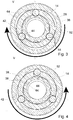
Figure 3 shows on a larger scale a cross-section in the plane III-III indicated inFigure 5 of the quick-release connector shown inFigure 2 in a locked condition; -
Figure 4 shows a cross-section of the quick-release connector shown inFigure 3 , in an unlocked condition; -
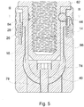
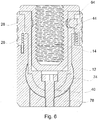
Figure 5 shows an axial section of the quick-release connector shown inFigures 3 and 4 in the plane V-V indicated inFigure 3 , in a locked condition; -
Figure 6 shows an axial section of the of the connector shown inFigure 5 in an unlocked condition; and -
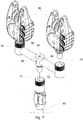
Figure 7 is a perspective view of an assembly comprising two quick-release connectors each as shown inFigure 2 in an assembled condition, connecting respective bite detectors to a buzz bar which itself is connected to a bank stick by way of a quick-release connector constituting a third embodiment of the present invention. -
Figure 1 shows a quick-release connector 10 comprising acylindrical pod 12 and acylindrical insert 14 which can be locked together in the manner described hereinafter. Thepod 12 comprises an outercylindrical shell 16 the exterior of which is provided with ashoulder 18 at an intended upper end of theshell 16, from which upwardly extends aneck portion 20. Asmall hole 22 extends downwardly into theshoulder 18 and receives oneend 24 of ahelical torsion spring 26 theother end 27 of which is received in a corresponding hole (not shown) in the interior of a locking component in the form of aknurled ring 28, when the connector is in the assembled condition with thering 28 sitting on theshoulder 18. - The
pod 12 further comprises an innercylindrical shell 30 having a circular-sectioned cylindricalouter surface 32 which fits snugly in a circular-sectioned cylindricalinner surface 33 of theouter shell 16. Theshell 30 also has a circular-sectioned cylindricalinner surface 34 defining a recess for theinsert 14. Thelower end 35 of theinner shell 30 is rounded so that it is a transverse portion which is received in a complementarily shaped internal recess (not shown) in theouter shell 16 when the connector is in an assembled condition, to inhibit relative rotation between the inner andouter shells inner shell 30 has aflange 36 at its upper end, and ashoulder 38 between theflange 36 and the cylindricalouter surface 32. In the assembled condition of theconnector 10, theshoulder 38 sits on the lip of theneck portion 20, thespring 26 surrounds theneck portion 20, and thering 28 is located betweenshoulder 18 of theouter shell 16 and theflange 36 of theinner shell 30. All these parts are held together by asingle bolt 40 which extends through thelower end 35 of theinner shell 30 into the lower end of theouter shell 16. - The
shoulder 38 of theinner shell 30 is provided with threecavities 42 constituted by circularly cylindrical through-holes which retain respective ball-bearings 44 which each have a diameter less than that of thecavity 42 in which it is retained. These holes are narrower at theirrespective inside ends 46, having there a diameter less than that of the ball-bearings 44, so that the ball-bearings 44 can not drop out into the interior of theshell 30. At the same time they can not drop outwardly from thecavities 42 because of the presence of thering 28 when theconnector 10 is in the assembled condition. - The
ring 28 has three equiangularly spacedprotuberances 48 on its interior just below its upper lip, and theinner shell 30 has three equiangularly spacedprotuberances 50 on the underside of itsflange 36. These protuberances are so located that they limit the amount of rotational movement available for thering 28 to about 60° when theconnector 10 is in the assembled condition. - The
ring 28 is provided withcams 52 around its interior having surfaces which vary in their distance from the axis of theconnector 10, between a distance from that axis substantially equal to the distance from that axis of the outer surface of theshoulder 38 of theinner shell 30 to a distance which is a little greater than the sum of the distance from that axis of the inner surface of theinner shell 30 and the diameter of one of the ball-bearings 44. - The
insert 14 is a very much simpler part than thepod 12, having a circularly-sectioned cylindricalouter surface 60 of a diameter just less than that of the interior cylindrical surface of theinner shell 30. Theinsert 14 has aflange 62 at its upper end. A series of part-spherical recesses 64 each of a radius of curvature about the same as that of the ball-bearings 44 are provided around the top of thecylindrical surface 60 under theflange 62. There are twelvesuch recesses 64, but there could be fewer or there could be more, provided there is at least one orientation in whichrespective recesses 64 are in alignment with thecavities 42 when theinsert 14 is inserted into theinner shell 30 of thepod 12. - The
insert 14 has aninternal screwthread 66 into which can be screwed the fastening screw of an angling device such as a bite detector 70 shown inFigure 7 . The underside of thepod 12 may be provided with a screw (not shown) for attachment to a bank stick for example, or anaperture 72 such as is shown in the modification ofFigure 2 , which receives ahollow end 74 of abuzz bar 76 formed with a through-hole (not shown) through which extends thebolt 40 into acap 78 located underneath thebuzz bar 76 when the assembly is complete, in the underside of theouter shell 16. - With the various parts of the
connector 10 in the assembled condition, and theinsert 14 inserted into thepod 12, thehelical torsion spring 26 urges thering 28 in the sense of the arrow inFigure 3 to bring thecams 52 into a position in which they hold the ball-bearings 44 in an engagement position in which they protrude through theinside ends 46 of thecavities 42, into respective ones of therecesses 64 of theinsert 14, as shown inFigures 3 and5 . This holds all the parts locked stationary together, including theinsert 14 within thepod 12. The only readily moveable part in this condition is rotation of thering 28 against the restoring force of thespring 26. This brings thecams 52 away from the ball-bearings 44 so that theinsert 16 can be lifted out of thepod 12 as the ball-bearings 44 are now free to retreat out of therecesses 64 as shown inFigures 4 and6 . - The
insert 14 can be reinserted and locked in thepod 12 by first rotating thering 28 against the restoring force of thespring 26, inserting theinsert 14 into thepod 12, releasing thering 28, and if necessary rotating theinsert 14 until portions of the ball-bearings 44 snap into therecesses 64. -
Figure 7 shows two quick-release connectors 10 each as shown inFigure 2 withrespective bite detectors 80 one of which is held by its associatedconnector 10 on thebuzz bar 82 and the other of which is to be so held as shown in that Figure.Figure 7 also shows at the middle of the buzz bar 82 a modified form of quick-release connector having all the features of that shown inFigure 1 except that theflange 62 is replaced by alarge head 84 with a through-hole 86 through which extends thebuzz bar 82, the internal screwthread being much smaller to receive a fixingscrew 88 to fix thebuzz bar 82 relative to thecentral connector 10, which is attached to the top of a bank-stick 90. - Many variations and modifications may occur to the reader without taking the resulting construction outside the scope of the present invention. To give an example only, the
cavities 42 could be a little smaller in diameter, and the ball-bearings 44 could be replaced by elongate locking members with rounded ends.
Claims (15)
- A quick-release connector for connecting a first part constituted by an angling device to a second part constituted by a bank stick or a buzz bar or other angling device, the quick-release connector comprising an insert having a circular cross-section and being secured to one of such first and second parts when the connector is in use, and a pod having a recess of circular cross-section to receive the insert and being secured to the other of such first and second parts when the connector is in use, the connector further comprising at least one displaceable locking member retained within the pod and being displaceable relative to the pod between an engagement position in which it engages the insert when the connector is in use to lock the insert and the pod and hence such first and second parts together when the connector is in use, and a non-engagement position in which it does not so engage the insert, and a locking component retained on the pod and moveable between a first position in which it holds the displaceable locking member in the said engagement position and a second position in which the locking member is released from the said engagement position,
characterised in that the movement of the locking component between its said first and second positions is a rotary movement. - A quick-release connector according to claim 1, characterised in that the said at least one displaceable locking member that is retained within the pod comprises a ball-bearing.
- A quick-release connector according to claim 1 or claim 2, characterised in that the insert is provided with at least one recess on an outer surface to receive the said at least one displaceable locking member.
- A quick-release connector according to claim 3, characterised in that the said at least one recess is part spherical.
- A quick-release connector according to claim 2 and claim 4, characterised in that the respective radii of curvature of the ball-bearing and the recess match.
- A quick-release connector according to any preceding claim, characterised in that the pod is provided with at least one guide cavity within which the said at least one locking member is retained and within which the said at least one locking member is guided between the said engagement and non-engagement positions.
- A quick-release connector according to claim 6, characterised in that there are a plurality of such cavities spaced apart around the pod and retaining respective locking members, and a plurality of recesses spaced apart around the insert, the angular spacing of the cavities and the recesses being the same to enable them to be brought into registration with one another.
- A quick-release connector according to any preceding claim, characterised in that the said locking component comprises a ring.
- A quick-release connector according to claim 8, characterised in that the ring is provided with at least one internal cam which engages the said at least one locking member when the connector is in use to move the locking member from its said non-engagement position to its said engagement position as the ring is rotated.
- A quick-release connector according to any preceding claim, characterised in that it further comprises a spring attached to the pod and the locking component in such a manner as to urge the locking component towards its said first position.
- A quick-release connector according to claim 10, characterised in that the spring is a helical torsion spring.
- A quick-release connector according to any preceding claim, characterised in that the pod is provided with an aperture for a buzz bar.
- A quick-release connector according to claim 12, characterised in that the pod is provided with a removable cap portion to facilitate securement of the pod to the buzz bar.
- A quick-release connector according to any preceding claim, characterised in that a bolt secures components of the pod to one another.
- An assembly comprising an angling device such as a bite detector connected to another angling device such as a bank stick or buzz bar by one or more quick-release connectors as claim in any preceding claim.
Applications Claiming Priority (1)
| Application Number | Priority Date | Filing Date | Title |
|---|---|---|---|
| GBGB1902914.9A GB201902914D0 (en) | 2019-03-04 | 2019-03-04 | A quick-release connector |
Publications (3)
| Publication Number | Publication Date |
|---|---|
| EP3704936A1 true EP3704936A1 (en) | 2020-09-09 |
| EP3704936B1 EP3704936B1 (en) | 2024-03-27 |
| EP3704936C0 EP3704936C0 (en) | 2024-03-27 |
Family
ID=66377475
Family Applications (1)
| Application Number | Title | Priority Date | Filing Date |
|---|---|---|---|
| EP20158904.1A Active EP3704936B1 (en) | 2019-03-04 | 2020-02-21 | A quick-release connector |
Country Status (5)
| Country | Link |
|---|---|
| EP (1) | EP3704936B1 (en) |
| ES (1) | ES2976435T3 (en) |
| GB (1) | GB201902914D0 (en) |
| HU (1) | HUE066167T2 (en) |
| PL (1) | PL3704936T3 (en) |
Cited By (2)
| Publication number | Priority date | Publication date | Assignee | Title |
|---|---|---|---|---|
| EP4361457A1 (en) * | 2022-10-24 | 2024-05-01 | Anchor Lås AB | A lock device for securing a fastening element |
| US20240392823A1 (en) * | 2023-05-24 | 2024-11-28 | The Boeing Company | Quick Release Pin |
Citations (4)
| Publication number | Priority date | Publication date | Assignee | Title |
|---|---|---|---|---|
| GB2403120A (en) | 2003-06-24 | 2004-12-29 | Svendsen Sports | Connecting device for angling equipment |
| US20090148230A1 (en) * | 2006-05-17 | 2009-06-11 | Andre Laisement | System for locking a first shaft with respect to a second shaft eliminating clearances between said shafts |
| GB2509107A (en) * | 2012-12-20 | 2014-06-25 | A & S Tasker Internat Ltd | Fishing rod support |
| CN205884439U (en) * | 2016-08-11 | 2017-01-18 | 刘敏敏 | Novel connector of diddle -net pole and diddle -net head |
-
2019
- 2019-03-04 GB GBGB1902914.9A patent/GB201902914D0/en not_active Ceased
-
2020
- 2020-02-21 HU HUE20158904A patent/HUE066167T2/en unknown
- 2020-02-21 PL PL20158904.1T patent/PL3704936T3/en unknown
- 2020-02-21 ES ES20158904T patent/ES2976435T3/en active Active
- 2020-02-21 EP EP20158904.1A patent/EP3704936B1/en active Active
Patent Citations (4)
| Publication number | Priority date | Publication date | Assignee | Title |
|---|---|---|---|---|
| GB2403120A (en) | 2003-06-24 | 2004-12-29 | Svendsen Sports | Connecting device for angling equipment |
| US20090148230A1 (en) * | 2006-05-17 | 2009-06-11 | Andre Laisement | System for locking a first shaft with respect to a second shaft eliminating clearances between said shafts |
| GB2509107A (en) * | 2012-12-20 | 2014-06-25 | A & S Tasker Internat Ltd | Fishing rod support |
| CN205884439U (en) * | 2016-08-11 | 2017-01-18 | 刘敏敏 | Novel connector of diddle -net pole and diddle -net head |
Cited By (2)
| Publication number | Priority date | Publication date | Assignee | Title |
|---|---|---|---|---|
| EP4361457A1 (en) * | 2022-10-24 | 2024-05-01 | Anchor Lås AB | A lock device for securing a fastening element |
| US20240392823A1 (en) * | 2023-05-24 | 2024-11-28 | The Boeing Company | Quick Release Pin |
Also Published As
| Publication number | Publication date |
|---|---|
| EP3704936B1 (en) | 2024-03-27 |
| PL3704936T3 (en) | 2024-07-29 |
| GB201902914D0 (en) | 2019-04-17 |
| HUE066167T2 (en) | 2024-07-28 |
| ES2976435T3 (en) | 2024-08-01 |
| EP3704936C0 (en) | 2024-03-27 |
Similar Documents
| Publication | Publication Date | Title |
|---|---|---|
| EP3704936B1 (en) | A quick-release connector | |
| CN114245754A (en) | Adjustable weight lifting device | |
| EP2335625B1 (en) | Bone anchoring device | |
| US7618417B2 (en) | Clamp for multiple rod shaped elements | |
| US10036611B1 (en) | Crosslock assembly | |
| US5094643A (en) | Connecting device for toy construction elements | |
| CN102525616B (en) | There is the Polyaxial bone anchoring device of the angle of pivot of expansion | |
| EP2468198A1 (en) | Bone anchoring device | |
| US10928158B2 (en) | Expandable telescopic baton | |
| US7125379B2 (en) | Surgical support arm docking apparatus | |
| KR20160018731A (en) | Head assembly for supporting and adjusting the position of an optical or electronic device | |
| TW201406340A (en) | Multi-axis bone fixation device | |
| EP4211364B1 (en) | A connector assembly for connecting a rope to a tubular frame | |
| JP6764284B2 (en) | Spine implant | |
| EP3058885B1 (en) | Bone plate | |
| TW201402063A (en) | Polyaxial bone anchoring device | |
| US10975907B2 (en) | One-hand operable end fitting connector assembly | |
| US10960258B2 (en) | Exercise machine connector | |
| US20010035646A1 (en) | Tube connecting device | |
| US8075598B2 (en) | Pedicle screw with a closure device | |
| US20240392823A1 (en) | Quick Release Pin | |
| WO2017115313A1 (en) | Support for portable electronic apparatuses | |
| JP6792789B2 (en) | adapter | |
| EP4437983A1 (en) | Coupling device for coupling a rod to a bone anchor and system of such a coupling device and at least two bone anchors | |
| KR20190116489A (en) | Fastening Devices and Fastening Sub-Assemblies |
Legal Events
| Date | Code | Title | Description |
|---|---|---|---|
| PUAI | Public reference made under article 153(3) epc to a published international application that has entered the european phase |
Free format text: ORIGINAL CODE: 0009012 |
|
| STAA | Information on the status of an ep patent application or granted ep patent |
Free format text: STATUS: THE APPLICATION HAS BEEN PUBLISHED |
|
| AK | Designated contracting states |
Kind code of ref document: A1 Designated state(s): AL AT BE BG CH CY CZ DE DK EE ES FI FR GB GR HR HU IE IS IT LI LT LU LV MC MK MT NL NO PL PT RO RS SE SI SK SM TR |
|
| AX | Request for extension of the european patent |
Extension state: BA ME |
|
| STAA | Information on the status of an ep patent application or granted ep patent |
Free format text: STATUS: REQUEST FOR EXAMINATION WAS MADE |
|
| 17P | Request for examination filed |
Effective date: 20210309 |
|
| RBV | Designated contracting states (corrected) |
Designated state(s): AL AT BE BG CH CY CZ DE DK EE ES FI FR GB GR HR HU IE IS IT LI LT LU LV MC MK MT NL NO PL PT RO RS SE SI SK SM TR |
|
| GRAP | Despatch of communication of intention to grant a patent |
Free format text: ORIGINAL CODE: EPIDOSNIGR1 |
|
| STAA | Information on the status of an ep patent application or granted ep patent |
Free format text: STATUS: GRANT OF PATENT IS INTENDED |
|
| INTG | Intention to grant announced |
Effective date: 20231215 |
|
| GRAS | Grant fee paid |
Free format text: ORIGINAL CODE: EPIDOSNIGR3 |
|
| GRAA | (expected) grant |
Free format text: ORIGINAL CODE: 0009210 |
|
| STAA | Information on the status of an ep patent application or granted ep patent |
Free format text: STATUS: THE PATENT HAS BEEN GRANTED |
|
| AK | Designated contracting states |
Kind code of ref document: B1 Designated state(s): AL AT BE BG CH CY CZ DE DK EE ES FI FR GB GR HR HU IE IS IT LI LT LU LV MC MK MT NL NO PL PT RO RS SE SI SK SM TR |
|
| REG | Reference to a national code |
Ref country code: GB Ref legal event code: FG4D |
|
| REG | Reference to a national code |
Ref country code: CH Ref legal event code: EP |
|
| REG | Reference to a national code |
Ref country code: DE Ref legal event code: R096 Ref document number: 602020027760 Country of ref document: DE |
|
| REG | Reference to a national code |
Ref country code: IE Ref legal event code: FG4D |
|
| U01 | Request for unitary effect filed |
Effective date: 20240402 |
|
| U07 | Unitary effect registered |
Designated state(s): AT BE BG DE DK EE FI FR IT LT LU LV MT NL PT SE SI Effective date: 20240408 |
|
| PG25 | Lapsed in a contracting state [announced via postgrant information from national office to epo] |
Ref country code: GR Free format text: LAPSE BECAUSE OF FAILURE TO SUBMIT A TRANSLATION OF THE DESCRIPTION OR TO PAY THE FEE WITHIN THE PRESCRIBED TIME-LIMIT Effective date: 20240628 |
|
| PG25 | Lapsed in a contracting state [announced via postgrant information from national office to epo] |
Ref country code: RS Free format text: LAPSE BECAUSE OF FAILURE TO SUBMIT A TRANSLATION OF THE DESCRIPTION OR TO PAY THE FEE WITHIN THE PRESCRIBED TIME-LIMIT Effective date: 20240627 Ref country code: HR Free format text: LAPSE BECAUSE OF FAILURE TO SUBMIT A TRANSLATION OF THE DESCRIPTION OR TO PAY THE FEE WITHIN THE PRESCRIBED TIME-LIMIT Effective date: 20240327 |
|
| REG | Reference to a national code |
Ref country code: HU Ref legal event code: AG4A Ref document number: E066167 Country of ref document: HU |
|
| PG25 | Lapsed in a contracting state [announced via postgrant information from national office to epo] |
Ref country code: RS Free format text: LAPSE BECAUSE OF FAILURE TO SUBMIT A TRANSLATION OF THE DESCRIPTION OR TO PAY THE FEE WITHIN THE PRESCRIBED TIME-LIMIT Effective date: 20240627 Ref country code: NO Free format text: LAPSE BECAUSE OF FAILURE TO SUBMIT A TRANSLATION OF THE DESCRIPTION OR TO PAY THE FEE WITHIN THE PRESCRIBED TIME-LIMIT Effective date: 20240627 Ref country code: HR Free format text: LAPSE BECAUSE OF FAILURE TO SUBMIT A TRANSLATION OF THE DESCRIPTION OR TO PAY THE FEE WITHIN THE PRESCRIBED TIME-LIMIT Effective date: 20240327 Ref country code: GR Free format text: LAPSE BECAUSE OF FAILURE TO SUBMIT A TRANSLATION OF THE DESCRIPTION OR TO PAY THE FEE WITHIN THE PRESCRIBED TIME-LIMIT Effective date: 20240628 |
|
| REG | Reference to a national code |
Ref country code: ES Ref legal event code: FG2A Ref document number: 2976435 Country of ref document: ES Kind code of ref document: T3 Effective date: 20240801 |
|
| U1N | Appointed representative for the unitary patent procedure changed after the registration of the unitary effect |
Representative=s name: MATHYS & SQUIRE; GB |
|
| PG25 | Lapsed in a contracting state [announced via postgrant information from national office to epo] |
Ref country code: IS Free format text: LAPSE BECAUSE OF FAILURE TO SUBMIT A TRANSLATION OF THE DESCRIPTION OR TO PAY THE FEE WITHIN THE PRESCRIBED TIME-LIMIT Effective date: 20240727 |
|
| PG25 | Lapsed in a contracting state [announced via postgrant information from national office to epo] |
Ref country code: SM Free format text: LAPSE BECAUSE OF FAILURE TO SUBMIT A TRANSLATION OF THE DESCRIPTION OR TO PAY THE FEE WITHIN THE PRESCRIBED TIME-LIMIT Effective date: 20240327 |
|
| PG25 | Lapsed in a contracting state [announced via postgrant information from national office to epo] |
Ref country code: SK Free format text: LAPSE BECAUSE OF FAILURE TO SUBMIT A TRANSLATION OF THE DESCRIPTION OR TO PAY THE FEE WITHIN THE PRESCRIBED TIME-LIMIT Effective date: 20240327 |
|
| PG25 | Lapsed in a contracting state [announced via postgrant information from national office to epo] |
Ref country code: SM Free format text: LAPSE BECAUSE OF FAILURE TO SUBMIT A TRANSLATION OF THE DESCRIPTION OR TO PAY THE FEE WITHIN THE PRESCRIBED TIME-LIMIT Effective date: 20240327 Ref country code: SK Free format text: LAPSE BECAUSE OF FAILURE TO SUBMIT A TRANSLATION OF THE DESCRIPTION OR TO PAY THE FEE WITHIN THE PRESCRIBED TIME-LIMIT Effective date: 20240327 Ref country code: IS Free format text: LAPSE BECAUSE OF FAILURE TO SUBMIT A TRANSLATION OF THE DESCRIPTION OR TO PAY THE FEE WITHIN THE PRESCRIBED TIME-LIMIT Effective date: 20240727 |
|
| REG | Reference to a national code |
Ref country code: DE Ref legal event code: R097 Ref document number: 602020027760 Country of ref document: DE |
|
| PLBE | No opposition filed within time limit |
Free format text: ORIGINAL CODE: 0009261 |
|
| STAA | Information on the status of an ep patent application or granted ep patent |
Free format text: STATUS: NO OPPOSITION FILED WITHIN TIME LIMIT |
|
| 26N | No opposition filed |
Effective date: 20250103 |
|
| U20 | Renewal fee for the european patent with unitary effect paid |
Year of fee payment: 6 Effective date: 20250219 |
|
| PGFP | Annual fee paid to national office [announced via postgrant information from national office to epo] |
Ref country code: PL Payment date: 20250211 Year of fee payment: 6 |
|
| PG25 | Lapsed in a contracting state [announced via postgrant information from national office to epo] |
Ref country code: MC Free format text: LAPSE BECAUSE OF FAILURE TO SUBMIT A TRANSLATION OF THE DESCRIPTION OR TO PAY THE FEE WITHIN THE PRESCRIBED TIME-LIMIT Effective date: 20240327 |
|
| REG | Reference to a national code |
Ref country code: CH Ref legal event code: PL |
|
| PG25 | Lapsed in a contracting state [announced via postgrant information from national office to epo] |
Ref country code: CH Free format text: LAPSE BECAUSE OF NON-PAYMENT OF DUE FEES Effective date: 20250228 |
|
| PGFP | Annual fee paid to national office [announced via postgrant information from national office to epo] |
Ref country code: HU Payment date: 20260206 Year of fee payment: 7 |
|
| U20 | Renewal fee for the european patent with unitary effect paid |
Year of fee payment: 7 Effective date: 20260223 |
|
| PGFP | Annual fee paid to national office [announced via postgrant information from national office to epo] |
Ref country code: GB Payment date: 20260223 Year of fee payment: 7 |
|
| PGFP | Annual fee paid to national office [announced via postgrant information from national office to epo] |
Ref country code: ES Payment date: 20260319 Year of fee payment: 7 |
|
| PGFP | Annual fee paid to national office [announced via postgrant information from national office to epo] |
Ref country code: IE Payment date: 20260206 Year of fee payment: 7 |
|
| PGFP | Annual fee paid to national office [announced via postgrant information from national office to epo] |
Ref country code: RO Payment date: 20260204 Year of fee payment: 7 |
|
| PGFP | Annual fee paid to national office [announced via postgrant information from national office to epo] |
Ref country code: CZ Payment date: 20260205 Year of fee payment: 7 |