EP3704931A1 - Traveling vehicle - Google Patents
Traveling vehicle Download PDFInfo
- Publication number
- EP3704931A1 EP3704931A1 EP19213641.4A EP19213641A EP3704931A1 EP 3704931 A1 EP3704931 A1 EP 3704931A1 EP 19213641 A EP19213641 A EP 19213641A EP 3704931 A1 EP3704931 A1 EP 3704931A1
- Authority
- EP
- European Patent Office
- Prior art keywords
- control
- period
- control method
- motor
- traveling vehicle
- Prior art date
- Legal status (The legal status is an assumption and is not a legal conclusion. Google has not performed a legal analysis and makes no representation as to the accuracy of the status listed.)
- Granted
Links
Images


Classifications
-
- B—PERFORMING OPERATIONS; TRANSPORTING
- B60—VEHICLES IN GENERAL
- B60L—PROPULSION OF ELECTRICALLY-PROPELLED VEHICLES; SUPPLYING ELECTRIC POWER FOR AUXILIARY EQUIPMENT OF ELECTRICALLY-PROPELLED VEHICLES; ELECTRODYNAMIC BRAKE SYSTEMS FOR VEHICLES IN GENERAL; MAGNETIC SUSPENSION OR LEVITATION FOR VEHICLES; MONITORING OPERATING VARIABLES OF ELECTRICALLY-PROPELLED VEHICLES; ELECTRIC SAFETY DEVICES FOR ELECTRICALLY-PROPELLED VEHICLES
- B60L1/00—Supplying electric power to auxiliary equipment of vehicles
- B60L1/003—Supplying electric power to auxiliary equipment of vehicles to auxiliary motors, e.g. for pumps, compressors
-
- B—PERFORMING OPERATIONS; TRANSPORTING
- B60—VEHICLES IN GENERAL
- B60W—CONJOINT CONTROL OF VEHICLE SUB-UNITS OF DIFFERENT TYPE OR DIFFERENT FUNCTION; CONTROL SYSTEMS SPECIALLY ADAPTED FOR HYBRID VEHICLES; ROAD VEHICLE DRIVE CONTROL SYSTEMS FOR PURPOSES NOT RELATED TO THE CONTROL OF A PARTICULAR SUB-UNIT
- B60W10/00—Conjoint control of vehicle sub-units of different type or different function
- B60W10/20—Conjoint control of vehicle sub-units of different type or different function including control of steering systems
-
- A—HUMAN NECESSITIES
- A01—AGRICULTURE; FORESTRY; ANIMAL HUSBANDRY; HUNTING; TRAPPING; FISHING
- A01D—HARVESTING; MOWING
- A01D34/00—Mowers; Mowing apparatus of harvesters
- A01D34/006—Control or measuring arrangements
-
- A—HUMAN NECESSITIES
- A01—AGRICULTURE; FORESTRY; ANIMAL HUSBANDRY; HUNTING; TRAPPING; FISHING
- A01D—HARVESTING; MOWING
- A01D34/00—Mowers; Mowing apparatus of harvesters
- A01D34/01—Mowers; Mowing apparatus of harvesters characterised by features relating to the type of cutting apparatus
- A01D34/412—Mowers; Mowing apparatus of harvesters characterised by features relating to the type of cutting apparatus having rotating cutters
- A01D34/63—Mowers; Mowing apparatus of harvesters characterised by features relating to the type of cutting apparatus having rotating cutters having cutters rotating about a vertical axis
- A01D34/64—Mowers; Mowing apparatus of harvesters characterised by features relating to the type of cutting apparatus having rotating cutters having cutters rotating about a vertical axis mounted on a vehicle, e.g. a tractor, or drawn by an animal or a vehicle
-
- B—PERFORMING OPERATIONS; TRANSPORTING
- B60—VEHICLES IN GENERAL
- B60K—ARRANGEMENT OR MOUNTING OF PROPULSION UNITS OR OF TRANSMISSIONS IN VEHICLES; ARRANGEMENT OR MOUNTING OF PLURAL DIVERSE PRIME-MOVERS IN VEHICLES; AUXILIARY DRIVES FOR VEHICLES; INSTRUMENTATION OR DASHBOARDS FOR VEHICLES; ARRANGEMENTS IN CONNECTION WITH COOLING, AIR INTAKE, GAS EXHAUST OR FUEL SUPPLY OF PROPULSION UNITS IN VEHICLES
- B60K7/00—Disposition of motor in, or adjacent to, traction wheel
- B60K7/0007—Disposition of motor in, or adjacent to, traction wheel the motor being electric
-
- B—PERFORMING OPERATIONS; TRANSPORTING
- B60—VEHICLES IN GENERAL
- B60L—PROPULSION OF ELECTRICALLY-PROPELLED VEHICLES; SUPPLYING ELECTRIC POWER FOR AUXILIARY EQUIPMENT OF ELECTRICALLY-PROPELLED VEHICLES; ELECTRODYNAMIC BRAKE SYSTEMS FOR VEHICLES IN GENERAL; MAGNETIC SUSPENSION OR LEVITATION FOR VEHICLES; MONITORING OPERATING VARIABLES OF ELECTRICALLY-PROPELLED VEHICLES; ELECTRIC SAFETY DEVICES FOR ELECTRICALLY-PROPELLED VEHICLES
- B60L15/00—Methods, circuits, or devices for controlling the traction-motor speed of electrically-propelled vehicles
- B60L15/02—Methods, circuits, or devices for controlling the traction-motor speed of electrically-propelled vehicles characterised by the form of the current used in the control circuit
-
- B—PERFORMING OPERATIONS; TRANSPORTING
- B62—LAND VEHICLES FOR TRAVELLING OTHERWISE THAN ON RAILS
- B62D—MOTOR VEHICLES; TRAILERS
- B62D11/00—Steering non-deflectable wheels; Steering endless tracks or the like
- B62D11/001—Steering non-deflectable wheels; Steering endless tracks or the like control systems
- B62D11/003—Electric or electronic control systems
-
- B—PERFORMING OPERATIONS; TRANSPORTING
- B62—LAND VEHICLES FOR TRAVELLING OTHERWISE THAN ON RAILS
- B62D—MOTOR VEHICLES; TRAILERS
- B62D11/00—Steering non-deflectable wheels; Steering endless tracks or the like
- B62D11/02—Steering non-deflectable wheels; Steering endless tracks or the like by differentially driving ground-engaging elements on opposite vehicle sides
- B62D11/04—Steering non-deflectable wheels; Steering endless tracks or the like by differentially driving ground-engaging elements on opposite vehicle sides by means of separate power sources
-
- H—ELECTRICITY
- H02—GENERATION; CONVERSION OR DISTRIBUTION OF ELECTRIC POWER
- H02K—DYNAMO-ELECTRIC MACHINES
- H02K7/00—Arrangements for handling mechanical energy structurally associated with dynamo-electric machines, e.g. structural association with mechanical driving motors or auxiliary dynamo-electric machines
- H02K7/006—Structural association of a motor or generator with the drive train of a motor vehicle
-
- B—PERFORMING OPERATIONS; TRANSPORTING
- B60—VEHICLES IN GENERAL
- B60K—ARRANGEMENT OR MOUNTING OF PROPULSION UNITS OR OF TRANSMISSIONS IN VEHICLES; ARRANGEMENT OR MOUNTING OF PLURAL DIVERSE PRIME-MOVERS IN VEHICLES; AUXILIARY DRIVES FOR VEHICLES; INSTRUMENTATION OR DASHBOARDS FOR VEHICLES; ARRANGEMENTS IN CONNECTION WITH COOLING, AIR INTAKE, GAS EXHAUST OR FUEL SUPPLY OF PROPULSION UNITS IN VEHICLES
- B60K7/00—Disposition of motor in, or adjacent to, traction wheel
- B60K2007/0038—Disposition of motor in, or adjacent to, traction wheel the motor moving together with the wheel axle
-
- B—PERFORMING OPERATIONS; TRANSPORTING
- B60—VEHICLES IN GENERAL
- B60L—PROPULSION OF ELECTRICALLY-PROPELLED VEHICLES; SUPPLYING ELECTRIC POWER FOR AUXILIARY EQUIPMENT OF ELECTRICALLY-PROPELLED VEHICLES; ELECTRODYNAMIC BRAKE SYSTEMS FOR VEHICLES IN GENERAL; MAGNETIC SUSPENSION OR LEVITATION FOR VEHICLES; MONITORING OPERATING VARIABLES OF ELECTRICALLY-PROPELLED VEHICLES; ELECTRIC SAFETY DEVICES FOR ELECTRICALLY-PROPELLED VEHICLES
- B60L2200/00—Type of vehicles
- B60L2200/40—Working vehicles
-
- B—PERFORMING OPERATIONS; TRANSPORTING
- B60—VEHICLES IN GENERAL
- B60L—PROPULSION OF ELECTRICALLY-PROPELLED VEHICLES; SUPPLYING ELECTRIC POWER FOR AUXILIARY EQUIPMENT OF ELECTRICALLY-PROPELLED VEHICLES; ELECTRODYNAMIC BRAKE SYSTEMS FOR VEHICLES IN GENERAL; MAGNETIC SUSPENSION OR LEVITATION FOR VEHICLES; MONITORING OPERATING VARIABLES OF ELECTRICALLY-PROPELLED VEHICLES; ELECTRIC SAFETY DEVICES FOR ELECTRICALLY-PROPELLED VEHICLES
- B60L2240/00—Control parameters of input or output; Target parameters
- B60L2240/40—Drive Train control parameters
- B60L2240/42—Drive Train control parameters related to electric machines
- B60L2240/421—Speed
-
- B—PERFORMING OPERATIONS; TRANSPORTING
- B60—VEHICLES IN GENERAL
- B60W—CONJOINT CONTROL OF VEHICLE SUB-UNITS OF DIFFERENT TYPE OR DIFFERENT FUNCTION; CONTROL SYSTEMS SPECIALLY ADAPTED FOR HYBRID VEHICLES; ROAD VEHICLE DRIVE CONTROL SYSTEMS FOR PURPOSES NOT RELATED TO THE CONTROL OF A PARTICULAR SUB-UNIT
- B60W2300/00—Indexing codes relating to the type of vehicle
- B60W2300/15—Agricultural vehicles
- B60W2300/156—Ridable lawn mowers
-
- B—PERFORMING OPERATIONS; TRANSPORTING
- B60—VEHICLES IN GENERAL
- B60W—CONJOINT CONTROL OF VEHICLE SUB-UNITS OF DIFFERENT TYPE OR DIFFERENT FUNCTION; CONTROL SYSTEMS SPECIALLY ADAPTED FOR HYBRID VEHICLES; ROAD VEHICLE DRIVE CONTROL SYSTEMS FOR PURPOSES NOT RELATED TO THE CONTROL OF A PARTICULAR SUB-UNIT
- B60W2520/00—Input parameters relating to overall vehicle dynamics
- B60W2520/40—Torque distribution
- B60W2520/403—Torque distribution between front and rear axle
-
- B—PERFORMING OPERATIONS; TRANSPORTING
- B60—VEHICLES IN GENERAL
- B60W—CONJOINT CONTROL OF VEHICLE SUB-UNITS OF DIFFERENT TYPE OR DIFFERENT FUNCTION; CONTROL SYSTEMS SPECIALLY ADAPTED FOR HYBRID VEHICLES; ROAD VEHICLE DRIVE CONTROL SYSTEMS FOR PURPOSES NOT RELATED TO THE CONTROL OF A PARTICULAR SUB-UNIT
- B60W2520/00—Input parameters relating to overall vehicle dynamics
- B60W2520/40—Torque distribution
- B60W2520/406—Torque distribution between left and right wheel
-
- B—PERFORMING OPERATIONS; TRANSPORTING
- B60—VEHICLES IN GENERAL
- B60Y—INDEXING SCHEME RELATING TO ASPECTS CROSS-CUTTING VEHICLE TECHNOLOGY
- B60Y2200/00—Type of vehicle
- B60Y2200/20—Off-Road Vehicles
- B60Y2200/22—Agricultural vehicles
- B60Y2200/223—Ridable lawn mowers
-
- Y—GENERAL TAGGING OF NEW TECHNOLOGICAL DEVELOPMENTS; GENERAL TAGGING OF CROSS-SECTIONAL TECHNOLOGIES SPANNING OVER SEVERAL SECTIONS OF THE IPC; TECHNICAL SUBJECTS COVERED BY FORMER USPC CROSS-REFERENCE ART COLLECTIONS [XRACs] AND DIGESTS
- Y02—TECHNOLOGIES OR APPLICATIONS FOR MITIGATION OR ADAPTATION AGAINST CLIMATE CHANGE
- Y02T—CLIMATE CHANGE MITIGATION TECHNOLOGIES RELATED TO TRANSPORTATION
- Y02T10/00—Road transport of goods or passengers
- Y02T10/60—Other road transportation technologies with climate change mitigation effect
- Y02T10/64—Electric machine technologies in electromobility
-
- Y—GENERAL TAGGING OF NEW TECHNOLOGICAL DEVELOPMENTS; GENERAL TAGGING OF CROSS-SECTIONAL TECHNOLOGIES SPANNING OVER SEVERAL SECTIONS OF THE IPC; TECHNICAL SUBJECTS COVERED BY FORMER USPC CROSS-REFERENCE ART COLLECTIONS [XRACs] AND DIGESTS
- Y02—TECHNOLOGIES OR APPLICATIONS FOR MITIGATION OR ADAPTATION AGAINST CLIMATE CHANGE
- Y02T—CLIMATE CHANGE MITIGATION TECHNOLOGIES RELATED TO TRANSPORTATION
- Y02T10/00—Road transport of goods or passengers
- Y02T10/60—Other road transportation technologies with climate change mitigation effect
- Y02T10/72—Electric energy management in electromobility
Definitions
- the present invention relates to a traveling vehicle capable of driving a pair of left and right driving wheels independently of each other.
- Patent Document 1 discloses a control device for a vehicle which controls a current of a motor for driving wheels of the vehicle by the PID control.
- This control device includes an integral term correction gain calculation section.
- the integral term correction gain calculation section calculates an integral term correction gain for correction of an output of an integral term of the PID control in order to be able to stabilize the behavior of the vehicle even in the event of occurrence of "wobbling" in steering.
- Such integral term correction gain is calculated based on a steering angle calculated from a yaw rate and a steering angle provided by the driver.
- the yaw rate is obtained from a curvature of the traveling path and a vehicle speed.
- the integral term correction gain is calculated based on a differential value obtained by time differentiation of result of comparison between the steering angle calculated from the yaw rate and the driver's steering angle.
- this control device is configured such that the greater the differential value, the smaller the integral term correction gain.
- Patent Document 1 JP2017-132406A
- some traveling vehicles are configured such that a small turning travel is made possible by rotating one of the pair of left and right motors and stopping the other and causing it to spin-turn at its present position.
- an operational position of an operational lever for giving a driver's instruction to one motor is often a position corresponding to a low-speed instruction near the zero speed.
- an integral term correction gain is set based on a differential value obtained by the time differentiation of the result of comparison between a steering angle calculated from a yaw rate and a steering angle provided by the driver, there is possibility of the driving wheels may be locked at the zero speed or at an extremely low speed. As a result, a feeling of discomfort or "wrongness" may be provided to the user.
- the traveling vehicle comprises:
- control parameters a control gain, various limit values, switchover of control mode or algorithm, maps, ON/OFF of energization of motors, etc.
- the setting section progressively decreases a ratio of one of the period of the first control method and the period of the second control method within the control cycle from 100% to 0% and progressively increases a ratio of the other of the period of the first control method and the period of the second control method within the control cycle from 0% to 100%.
- the ratio of the other of the period of the first control method and the period of the second control method within the control cycle is progressively increased.
- the control cycle is caused to undergo an intermediate (transitional) state between the state of the control cycle consisting entirely of the period of the first control method and the state of the control cycle consisting entirely of the period of the second control method. Therefore, irregularity in the control parameter at the time of switchover of the control method can be alleviated, thus realizing smooth switchover of the control method.
- change of control parameter is possible in a manner similar to that of the known DUTY control, so the control can be carried out easily.
- the setting section sets the period of the first control method within the control cycle to zero when a rotational speed of the motor is less than a predetermined rotational speed and sets the period of the second control method within the control cycle to zero when the rotational speed of the motor is equal to or greater than the predetermined rotational speed.
- the setting section is configured to set both the period of the first control method and the period of the second control method within the control cycle to values greater than zero, in case the operational amount increase the rotational speed of the motor at the time of reception of this operational amount to be greater than a preset change amount.
- the pair of left and right driving wheels are used also as steerable wheels.
- a traveling vehicle relating to the present invention is configured to be able to travel smoothly even when a control method of motors is switched over. Next, a traveling vehicle 1 according to the instant embodiment will be explained.
- Fig. 1 shows a perspective view of a riding electric grass cutting machine as an example of the traveling vehicle 1 according to the instant embodiment.
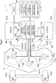
- Fig. 2 shows a system diagram showing an electric system and a power system of the traveling vehicle 1.
- a riding electric grass cutting machine which travels in a field while carrying out a grass (lawn) cutting work will be explained.
- An electric power control device 9 controls power used by the traveling vehicle 1 which travels while carrying out a utility work (a grass cutting work).
- the electric power used by the traveling vehicle 1 includes electric power used for traveling of the traveling vehicle 1, electric power used for the utility work carried out by the traveling vehicle 1, and electric power used for a user who uses the traveling vehicle 1.
- a specific example of the electric power used for traveling of the traveling vehicle 1 is electric power supplied to motors 20 which respectively drive a pair of left and right driving wheels 3 included in the traveling vehicle 1.
- a specific example of the electric power used for a utility work carried out by the traveling vehicle 1 is electric power to be supplied to motors ("mower motors 130a, 130b, 130c" to be described later) which rotate cutter blades used for a grass cutting work.
- a specific example of the electric power used for a user who uses the traveling vehicle 1 is electric power used for displaying by an instrument panel 99.
- the electric power control device 9 is mounted on the traveling vehicle 1 that carries out such work.
- the electric power control device 9 distributes the respective electric powers appropriately to functional sections for carrying out the respective functions.
- the riding electric grass cutting machine includes a machine body 4, a battery 23, a driver's seat 11, a ROPS frame 12 and a mower unit 13.
- the machine body 4 is supported by caster wheels 5 constituting front wheels and driving wheels 3 constituting rear wheels.
- the battery 23 is disposed at a rear portion of the machine body 4.
- the driver's seat 11 is disposed forwardly of the battery 23.
- the ROPS frame 12 is mounted erect from the rear side of the driver's seat 11.
- the mower unit 13 is an example of a utility work unit. This mower unit 13 is suspended from the machine body 4 to be lifted up/down via a lift (elevating/lowering) mechanism in a space beneath the machine body 4 and between the caster wheels 5 and the driving wheels 3.
- the driving wheels 3 are driven by a traveling control unit 6. Operations of this traveling control unit 6 are controlled by a traveling control device 2. Operations of the mower unit 13 are controlled by a mower control device 7.
- the caster wheels 5 consist of a left caster wheel 5a and a right caster wheel 5b and the driving wheels 3 consist of a left driving wheel 3a and a right driving wheel 3b.
- a floor plate acting as a "footrest” for the driver there is provided a floor plate acting as a "footrest” for the driver. From this floor plate, a brake pedal 14 protrudes.
- a left maneuvering lever 8a and a right maneuvering lever 8b On the left and right opposed sides of the driver's seat 11, there are disposed a left maneuvering lever 8a and a right maneuvering lever 8b.
- an electric operational panel 18 includes switch buttons, switch levers or the like of the electric control system.
- a mower switch for activating the mower unit 13 and the instrument panel 99 described above are disposed.
- the above-described left maneuvering lever 8a and the right maneuvering lever 8b will be generically referred to as "maneuvering lever 8" when no distinction therebetween is particularly needed.
- power sources for the left driving wheel 3a and the right driving wheel 3b are rotational forces from a left motor 21 and a right motor 22, respectively. Both the left motor 21 and the right motor 22 are in-wheel motors. Via a left power supply section 41, electric power is supplied to the left motor 21. The left power supply section 41 is included in an inverter 10. Via a right power supply section 42, electric power is supplied to the right motor 22. The right power supply section 42 also is included in the inverter 10. By changing the supplied electric powers respectively, it is possible to change at least one of a rotational speed and a torque. With this, respective rotational speeds (actual speeds) of the left driving wheel 3a and the right driving wheel 3b can be made different from each other. As a result, due to a rotational speed difference between the left driving wheel 3a and the right driving wheel 3b, the riding electric grass cutting machine makes a turn.
- the traveling control unit 6 is a functional section for controlling traveling and turning of the riding electric grass cutting machine.
- the traveling control unit 6 includes the left motor 21, the right motor 22 and the inverter 10 (in particular, the left power supply section 41 and the right power supply section 42) which were mentioned above.
- the inverter 10 supplies electric power to the left motor 21 and the right motor 22 respectively.
- Electric power outputted from the inverter 10 corresponds to a speed instruction value (a target value) calculated by the traveling control device 2.
- a target value calculated by the traveling control device 2.
- the actual rotational speed the actual speed
- the actual speed becomes smaller than a target value due to a traveling load
- the electric power outputted from the inverter 10 will be corrected to increase the motor output torque.
- the electric power outputted from the inverter 10 will be corrected to decrease the motor output torque.
- the mower unit 13 includes three rotary blades 131a, 131b, 131c. These rotary blades 131a, 131b, 131c respectively use the mower motors 130a, 130b, 130c as their driving power sources. Electric power supplies to the mower motors 130a, 130b, 130c are carried out via a mower power supply section 43. This mower power supply section 43 too is included in the inverter 10. The mower power supply section 43 is controlled by the mower control device 7. This mower control device 7 constitutes a control device 100 together with the traveling control device 2 and the electric power control device 9 which were described above.
- An operational amount (a pivot angle) of the left maneuvering lever 8a is detected by a left maneuvering angle detection sensor 80a.
- an operational angle of the brake pedal 14 is detected by a brake detection sensor 80c.
- An operation of the mower switch is detected by a mower sensor 80d.
- a rotational speed of the left driving wheel 3a is detected by a left rear wheel rotation detection sensor 70a.
- a rotational speed of the right driving wheel 3b is detected by a right rear wheel rotation detection sensor 70b.
- rotational speeds of the mower motors 130a, 130b, 130c are detected respectively by rotation sensors 100a, 100b, 100c. And, detection results from the respective sensors are transmitted to the control device 100 to be used by this control device 100 when necessary or appropriate.
- the traveling control device 2 based on operational amount of the respective maneuvering levers 8, electric powers to be supplied respectively to the left motor 21 and the right motor 22 are calculated. Further, in this traveling control device 2, by a known feedback control technique, the above-describe electric powers are corrected. Namely, the traveling control device 2 calculates required driving torques (to be referred to simply as “necessary torques" hereinafter) required by the left motor 21 and the right motor 22.
- the necessary torques means a torque amount required by the left motor 21 or the right motor 22 for the actual speed to reach the target speed in case an actual rotational speed has not arrived at a target rotational speed with a control amount calculated by a target rotational speed set in correspondence with an operational amount by the left maneuvering lever 8a or the right maneuvering lever 8b.
- the traveling control device 2 derives such necessary torques from the target rotational speeds of the left driving wheel 3a and the right driving wheel 3b and the actual rotational speeds of the left driving wheel 3a and the right driving wheel 3b.
- Such target rotational speeds of the left driving wheel 3a and the right driving wheel 3b are obtained, based on detection results of the left maneuvering angle detection sensor 80a and the right maneuvering angle detection sensor 80b.
- the actual rotational speeds of the left driving wheel 3a and the right driving wheel 3b are obtained by the left rear wheel rotation detection sensor 70a and the right rear wheel rotation detection sensor 70b respectively. Then, based on such calculated necessary torques, the traveling control device 2 corrects the electric power amounts.
- switchover function a function relating to switchover of a control method of the motors 20 relating to the instant embodiment.
- This switchover function is realized by the respective functional sections of the driving wheels 3, the motor 20, an operational amount reception section 51, a setting section 52 and a motor driving section 53.
- the operational amount reception section 51, the setting section 52 and the motor driving section 53 are constituted of hardware and/or software including a CPU as the core component thereof, in order to carry out processes relating to the above-described switchover function.
- the driving wheels 3 are provided in the machine body 4 as described above and consist of the left driving wheel 3a and the right driving wheel 3b, in the instant embodiment.
- the motor 20 is capable of driving the pair of left and right driving wheels 3 independently of each other. And, this motor 20 consists of the left motor 21 and the right motor 22 in this embodiment, as described above.
- the left motor 21 inputs a rotational force to the left driving wheel 3a.
- the right motor 22 inputs a rotational force to the right driving wheel 3b.
- the left driving wheel 3a and the right driving wheel 3b are configured to be able to input rotational forces of the left motor 21 and the right motor 22, independently of each other.
- the traveling vehicle 1 makes a turn.
- the pair of left and right driving wheels 3 are used also as steerable wheels.
- the operational amount reception section 51 is capable of receiving the operational amounts respectively for the pair of left and right motors 20.
- the left maneuvering lever 8a and the right maneuvering lever 8b are disposed on the left and right opposed sides of the driver's seat 11.
- the left maneuvering lever 8a and the right maneuvering lever 8b are operated by a user.
- the maneuvering lever 8 consisting of the left maneuvering lever 8a and the right maneuvering lever 8b corresponds to the operational amount reception section 51. And, the maneuvering levers 8 receive operational amounts for the pair of left and right motors 20.
- the setting section 52 can set a period of the first control method and a period of the second control method within a predetermined control cycle T for controlling driving of the motors 20, in accordance with the operational amounts.
- the first control method includes a predetermined first control parameter.
- the second control method includes a predetermined second control parameter.
- the "operational amounts" mean operational amounts received by the above-described operational amount reception section 51 and the operational amounts will be transmitted from the operational amount reception section 51 to the setting section 52.
- the motors 20 are controlled by the known PWM (Pulse Width Modulation) control technique. Therefore, the "predetermined control cycle T for controlling driving of the motors 20" corresponds to the control cycle T in the PWM control, namely, the reciprocal of the driving frequency value of the PWM control. For instance, 100 milliseconds may be employed as the control cycle T.
- PWM Pulse Width Modulation
- driving of the motors 20 can be controlled with switching over of two different control methods within one control cycle.
- One of such two control methods is the first control method including the predetermined first control parameter.
- the other of such two control methods is the second control method including the predetermined second control parameter.
- PI control is employed as the first control method including the predetermined first control parameter.
- the integral gain is a predetermined first value and the proportional gain is a predetermined second value.
- P control is employed as the second control method including the predetermined second control parameter.
- the integral gain is zero value and the proportional gain is a predetermined third value.
- the setting section 52 sets a period for effecting the PI control and a period for effecting the P control, within the control cycle T in the PWM control.
- control parameters used in the instant embodiment are control gains, various kinds of limit values, switchover of control mode or algorithm, maps, ON/OFF of motor energization, etc.
- Fig. 3 shows one example of the predetermined control cycle T set by the setting section 52.
- Such control cycle T in the PWM control is a fixed value (a constant) according to the control frequency.
- the setting section 52 sets, in this control cycle T, a P control period (tp) and a PI control period (tpi).
- the P control period (tp) is set to a period of 100% in the control cycle T and the PI control period (tpi) is set to 0% in the control cycle T, respectively.
- the P control period (tp) is set to a period of 75% in the control cycle T and the PI control period (tpi) is set to 25% in the control cycle T, respectively.
- the P control period (tp) is set to a period of 50% in the control cycle T and the PI control period (tpi) is set to 50% in the control cycle T, respectively.
- the P control period (tp) is set to a period of 25% in the control cycle T and the PI control period (tpi) is set to 75% in the control cycle T, respectively.
- the P control period (tp) is set to a period of 0% in the control cycle T and the PI control period (tpi) is set to 100% in the control cycle T, respectively.
- Fig.3 shows just one example.
- the ratio between the P control period (tp) and the PI control period (tpi) in the control cycle T may be any other ratio than those shown in Fig. 3 .
- the setting section 52 will set the PI control period (tpi) within the control cycle T to zero if the rotational speed of the motor 20 is less than a predetermined rotational speed or will set the P control period (tp) within the control cycle T to zero if the rotational speed of the motor 20 is equal to or greater than the predetermined rotational speed.
- the "rotational speed" of the motor 20 refers to the number of rotations of the left motor 21 or the right motor 22 within a predetermined period, which may be 1000 rpm, for example.
- the setting section 52 sets the PI control period (tpi) and the P control period (tp) within the control cycle T for the left motor 21 and sets the PI control period (tpi) and the P control period (tp) within the control cycle T for the right motor 22, independently of each other. Therefore, in case the rotational speed of the left motor 21 is less than 1000 rpm, the setting section 52 will set the PI control period (tpi) for the left motor 21 to zero as shown in Fig. 3(A) . Further, in case the rotational speed of the left motor 21 is equal to or greater than 1000 rpm, the setting section 52 will set the P control period (tp) for the left motor 21 to zero, as shown in Fig. 3(E) .
- the setting section 52 will set the PI control period (tpi) for the right motor 22 to zero as shown in Fig. 3(A) . Further, in case the rotational speed of the right motor 22 is equal to or greater than 1000 rpm, the setting section 52 will set the P control period (tp) for the right motor 22 to zero, as shown in Fig. 3(E) .
- the setting section 52 progressively reduces the ratio of the P control period (tp) within the control cycle T from 100% to 0% and also progressively increases the ratio of the PI control period (tpi) from 0% to 100%. Namely, in case the control method of driving the left motor 21 and the right motor 22 respectively is switched from the P control to the PI control, advantageously, the setting section 52 will switch over from the control state shown in Fig. 3(A) to the control state shown in Fig. 3(E) through transition of control states shown in Fig. 3(B) through (D) .
- the motor driving section 53 is capable of driving the motors 20 based on setting results made by the setting section 52.
- the setting results made by the setting section 52 are the control methods set by the setting section 52 for driving the motors 20. Therefore, to the motor driving section 53, control methods set by the setting section 52 for driving the motors 20 will be transmitted.
- the left power supply section 41 and the right power supply section 42 described above correspond to such motor driving section 53.
- the traveling vehicle 1 may be a tractor for carrying out a plowing work in a field for example, or may be a rice planting machine also. Still further, it may be a combine for carrying out a culm harvesting work in a field or may be a seed sowing machine for sowing seeds. Still further, it may be a riding management machine for carrying out e.g. a chemical agent spraying work, etc. Namely, specific examples of the traveling vehicle 1 include a grass cutting machine, a tractor, a rice planting machine, a combine, a seed sowing machine, a riding management machine, etc. Needless to say, the present invention is applicable also to a traveling vehicle 1 used for carrying out works different from the above in a field. Moreover, the present invention is applicable not only to a riding traveling vehicle 1, but also to a traveling vehicle 1 that can be remotely controlled.
- the first control method is the PI control and the second control method is the P control.
- the first control method and the second control method may be other control methods.
- the fuzzy control or neuro control may be employed, and the PID control may be employed also.
- the first control method and the second control method may be constituted of a same control method, with control parameters thereof being made different from each other.
- the setting section 52 progressively reduces the ratio of the P control period (tp) within the control cycle T from 100% to 0% and progressively increases the ratio of the PI control period (tpi) from 0% to 100%.
- the setting section 52 progressively reduces the ratio of the PI control period (tpi) within the control cycle T from 100% to 0% and progressively increases the ratio of the P control period (tp) from 0% to 100%.
- the setting section 52 does not change the ratio of the P control period (tp) and the ratio of the PI control period (tpi) within the control cycle T as fixed values, but changes the control cycle T instead.
- the setting section 52 sets the PI control period (tpi) of the left motor 21 to zero as shown in Fig. 3(A) and sets the P control period (tp) of the left motor 21 to zero as shown in Fig 3(E) when the rotational speed of the left motor 21 is equal to or greater than 1000 rpm and explained also that if the rotational speed of the right motor 22 is less than 1000 rpm for instance, the setting section 52 sets the PI control period (tpi) of the right motor 22 to zero as shown in Fig.
- the setting section 52 sets the period of the first control method within the control cycle T to zero in case the rotational speed of the motor 20 is less than a predetermined rotational speed and sets the period of the second control method within the control cycle T to zero in case the rotational speed of the motor 20 is equal to or greater than the predetermined rotational speed.
- the setting section 52 sets both the first control method period and the second control method period to values greater than zero.
- the motor 20 may be driven by the control method of Fig. 3(A) , whereas, in case there is an instruction for accelerating the traveling vehicle 1, the motor 20 will be driven by the control method of Fig. 3(E) .
- the switchover should be made from Fig. 3(A) to Fig. 3(E) , via the transition from Figs. 3(B) through (D) .
- the motor 20 will be driven by the control method of Fig.
- the motor 20 will be driven by the control method of Fig. 3(A) .
- the switchover should be made from Fig. 3 (E) to Fig. 3 (A) , via the transition from Figs. 3(D), (C), (B) .
- the "rotational speed of the motor 20 at the time of reception of an operational amount” corresponds to a rotational speed of the motor 20 immediately before the reception of the operational amount.
- the switchover of Figs. 3(B) through (D) can be made with using acceleration as a threshold value.
- the pair of left and right driving wheels 3 are employed as steerable wheels.
- the pair of left and right driving wheels 3 may not be employed as steerable wheels.
- the present invention is applicable to a traveling vehicle capable of driving a pair of left and right driving wheels independently of each other.
Landscapes
- Engineering & Computer Science (AREA)
- Mechanical Engineering (AREA)
- Transportation (AREA)
- Chemical & Material Sciences (AREA)
- Combustion & Propulsion (AREA)
- Power Engineering (AREA)
- Environmental Sciences (AREA)
- Life Sciences & Earth Sciences (AREA)
- Automation & Control Theory (AREA)
- Electric Propulsion And Braking For Vehicles (AREA)
- Guiding Agricultural Machines (AREA)
- Harvester Elements (AREA)
- Non-Deflectable Wheels, Steering Of Trailers, Or Other Steering (AREA)
Abstract
Description
- The present invention relates to a traveling vehicle capable of driving a pair of left and right driving wheels independently of each other.
- Conventionally, there has been used a traveling vehicle having a pair of left and right drive wheels that are driven independently of each other by a pair of left and right motors. As such traveling vehicle, there is one in which PI (Proportional-Integral) control is employed for controlling currents running in the motors. The PI control is known, so its detailed explanation is omitted herein. But, PI control effects control by combining the so-called proportional operation and the integral operation. A technique for controlling driving of a vehicle with utilization of PID (Proportional-Integral-Differential) control developed from such PI control is known from
e.g. Patent Document 1 identified below. -
Patent Document 1 discloses a control device for a vehicle which controls a current of a motor for driving wheels of the vehicle by the PID control. This control device includes an integral term correction gain calculation section. The integral term correction gain calculation section calculates an integral term correction gain for correction of an output of an integral term of the PID control in order to be able to stabilize the behavior of the vehicle even in the event of occurrence of "wobbling" in steering. Such integral term correction gain is calculated based on a steering angle calculated from a yaw rate and a steering angle provided by the driver. The yaw rate is obtained from a curvature of the traveling path and a vehicle speed. In particular, the integral term correction gain is calculated based on a differential value obtained by time differentiation of result of comparison between the steering angle calculated from the yaw rate and the driver's steering angle. And, this control device is configured such that the greater the differential value, the smaller the integral term correction gain. - Patent Document 1:
JP2017-132406A - For instance, some traveling vehicles are configured such that a small turning travel is made possible by rotating one of the pair of left and right motors and stopping the other and causing it to spin-turn at its present position. When such small-turn traveling is to be carried out, an operational position of an operational lever for giving a driver's instruction to one motor is often a position corresponding to a low-speed instruction near the zero speed. In such case, in the technique disclosed in
Patent Document 1, if an integral term correction gain is set based on a differential value obtained by the time differentiation of the result of comparison between a steering angle calculated from a yaw rate and a steering angle provided by the driver, there is possibility of the driving wheels may be locked at the zero speed or at an extremely low speed. As a result, a feeling of discomfort or "wrongness" may be provided to the user. - In view of the above, there is a need for a traveling vehicle capable of reducing such feeling of discomfort or wrongness to the user.
- According to a characterizing feature of a traveling vehicle relating to the present invention, the traveling vehicle comprises:
- a pair of left and right driving wheels;
- a pair of left and right motors capable of driving the pair of left and right driving wheels independently of each other;
- an operational amount reception section capable of receiving operational amounts respectively for the pair of left and right motors;
- a setting section capable of setting a period of a first control method having a predetermined first control parameter and a period of a second control method having a predetermined second control parameter, within a predetermined control cycle for controlling driving of the motors, in accordance with the operational amounts; and
- a motor driving section capable of driving the respective motors based on result of setting made by the setting section.
- With the above-described characterizing arrangement, in case the motors are controlled by a control method having set control parameters (a control gain, various limit values, switchover of control mode or algorithm, maps, ON/OFF of energization of motors, etc.), even if the user carries out an acceleration or deceleration, it is possible to improve discontinuity in the control parameters (in particular, a gain) at the time of switchover of the control method. Accordingly, in accordance with the operational amounts received by the operational amount reception section and without giving feeling of discomfort or wrongness to the user, the traveling vehicle is allowed to travel smoothly.
- Preferably, the setting section progressively decreases a ratio of one of the period of the first control method and the period of the second control method within the control cycle from 100% to 0% and progressively increases a ratio of the other of the period of the first control method and the period of the second control method within the control cycle from 0% to 100%.
- With the above-described arrangement, in association with the progressive reduction of the ratio of one of the period of the first control method and the period of the second control method within the control cycle, the ratio of the other of the period of the first control method and the period of the second control method within the control cycle is progressively increased. With this, the control cycle is caused to undergo an intermediate (transitional) state between the state of the control cycle consisting entirely of the period of the first control method and the state of the control cycle consisting entirely of the period of the second control method. Therefore, irregularity in the control parameter at the time of switchover of the control method can be alleviated, thus realizing smooth switchover of the control method. Moreover, with this above-described arrangement, change of control parameter is possible in a manner similar to that of the known DUTY control, so the control can be carried out easily.
- Further, preferably, the setting section sets the period of the first control method within the control cycle to zero when a rotational speed of the motor is less than a predetermined rotational speed and sets the period of the second control method within the control cycle to zero when the rotational speed of the motor is equal to or greater than the predetermined rotational speed.
- With the above-described arrangement, when the control method is switched over in accordance with a rotational speed, smooth traveling is made possible without giving feeling of discomfort or wrongness to the user with respect to the behavior of the traveling vehicle.
- Or, preferably, the setting section is configured to set both the period of the first control method and the period of the second control method within the control cycle to values greater than zero, in case the operational amount increase the rotational speed of the motor at the time of reception of this operational amount to be greater than a preset change amount.
- With the above-described arrangement, when the control method is to be switched over according to an acceleration, smooth traveling is made possible without giving feeling of discomfort or wrongness to the user respecting the behavior of the traveling vehicle.
- Further, preferably:
- the first control method is PI control in which an integral gain is a predetermined first value and a proportional gain is a predetermined second value; and
- the second control method is P control in which the integral gain is zero value and the proportional gain is a predetermined third value.
- With the above-described arrangement, when the control method is switched over between the PI control and the P control, smooth traveling is made possible without giving feeling of discomfort or wrongness to the user respecting the behavior of the traveling vehicle.
- Further, preferably, the pair of left and right driving wheels are used also as steerable wheels.
- With the above-described arrangement, e.g. also in case a turning is made by not rotating one of the pair of left and right driving wheels and driving the other of the pair of left and right driving wheels, it is possible to avoid giving damage to the road surface.
-
-
Fig. 1 is a perspective view of a traveling vehicle, -
Fig. 2 is a system diagram showing an electric system and a power system of the traveling vehicle, and -
Fig. 3 is an explanatory view of periods of P control and periods of PI control set within a control cycle. - A traveling vehicle relating to the present invention is configured to be able to travel smoothly even when a control method of motors is switched over. Next, a
traveling vehicle 1 according to the instant embodiment will be explained. -
Fig. 1 shows a perspective view of a riding electric grass cutting machine as an example of the travelingvehicle 1 according to the instant embodiment.Fig. 2 shows a system diagram showing an electric system and a power system of thetraveling vehicle 1. In the instant embodiment, as an example of thetraveling vehicle 1, a riding electric grass cutting machine which travels in a field while carrying out a grass (lawn) cutting work will be explained. - An electric
power control device 9 controls power used by thetraveling vehicle 1 which travels while carrying out a utility work (a grass cutting work). The electric power used by the travelingvehicle 1 includes electric power used for traveling of the travelingvehicle 1, electric power used for the utility work carried out by the travelingvehicle 1, and electric power used for a user who uses thetraveling vehicle 1. A specific example of the electric power used for traveling of the travelingvehicle 1 is electric power supplied to motors 20 which respectively drive a pair of left andright driving wheels 3 included in thetraveling vehicle 1. A specific example of the electric power used for a utility work carried out by the travelingvehicle 1 is electric power to be supplied to motors ("mower motors traveling vehicle 1 is electric power used for displaying by aninstrument panel 99. The electricpower control device 9 is mounted on thetraveling vehicle 1 that carries out such work. The electricpower control device 9 distributes the respective electric powers appropriately to functional sections for carrying out the respective functions. - As shown in
Fig. 1 andFig. 2 , the riding electric grass cutting machine includes amachine body 4, abattery 23, a driver'sseat 11, aROPS frame 12 and amower unit 13. Themachine body 4 is supported bycaster wheels 5 constituting front wheels and drivingwheels 3 constituting rear wheels. Thebattery 23 is disposed at a rear portion of themachine body 4. The driver'sseat 11 is disposed forwardly of thebattery 23. TheROPS frame 12 is mounted erect from the rear side of the driver'sseat 11. Themower unit 13 is an example of a utility work unit. Thismower unit 13 is suspended from themachine body 4 to be lifted up/down via a lift (elevating/lowering) mechanism in a space beneath themachine body 4 and between thecaster wheels 5 and thedriving wheels 3. - The
driving wheels 3 are driven by a traveling control unit 6. Operations of this traveling control unit 6 are controlled by a travelingcontrol device 2. Operations of themower unit 13 are controlled by a mower control device 7. Here, it is noted that thecaster wheels 5 consist of aleft caster wheel 5a and aright caster wheel 5b and thedriving wheels 3 consist of aleft driving wheel 3a and aright driving wheel 3b. - Forwardly of the driver's
seat 11, there is provided a floor plate acting as a "footrest" for the driver. From this floor plate, abrake pedal 14 protrudes. On the left and right opposed sides of the driver'sseat 11, there are disposed a left maneuvering lever 8a and a right maneuvering lever 8b. Further, on the side of the driver'sseat 11, there is provided an electricoperational panel 18. This electricoperational panel 18 includes switch buttons, switch levers or the like of the electric control system. On this electricoperational panel 18, a mower switch for activating themower unit 13 and theinstrument panel 99 described above are disposed. Incidentally, in the following explanation, the above-described left maneuvering lever 8a and the right maneuvering lever 8b will be generically referred to as "maneuveringlever 8" when no distinction therebetween is particularly needed. - In the instant embodiment, power sources for the
left driving wheel 3a and theright driving wheel 3b are rotational forces from a left motor 21 and a right motor 22, respectively. Both the left motor 21 and the right motor 22 are in-wheel motors. Via a left power supply section 41, electric power is supplied to the left motor 21. The left power supply section 41 is included in aninverter 10. Via a right power supply section 42, electric power is supplied to the right motor 22. The right power supply section 42 also is included in theinverter 10. By changing the supplied electric powers respectively, it is possible to change at least one of a rotational speed and a torque. With this, respective rotational speeds (actual speeds) of theleft driving wheel 3a and theright driving wheel 3b can be made different from each other. As a result, due to a rotational speed difference between theleft driving wheel 3a and theright driving wheel 3b, the riding electric grass cutting machine makes a turn. - The traveling control unit 6 is a functional section for controlling traveling and turning of the riding electric grass cutting machine. In the instant embodiment, the traveling control unit 6 includes the left motor 21, the right motor 22 and the inverter 10 (in particular, the left power supply section 41 and the right power supply section 42) which were mentioned above. The
inverter 10 supplies electric power to the left motor 21 and the right motor 22 respectively. Electric power outputted from theinverter 10 corresponds to a speed instruction value (a target value) calculated by the travelingcontrol device 2. When the actual rotational speed (the actual speed) becomes smaller than a target value due to a traveling load, the electric power outputted from theinverter 10 will be corrected to increase the motor output torque. On the other hand, in the case of e.g. traveling on a downslope, if the actual rotational speed (the actual speed) becomes greater than the target value, the electric power outputted from theinverter 10 will be corrected to decrease the motor output torque. - The
mower unit 13 includes threerotary blades rotary blades mower motors mower motors power supply section 43. This mowerpower supply section 43 too is included in theinverter 10. The mowerpower supply section 43 is controlled by the mower control device 7. This mower control device 7 constitutes acontrol device 100 together with the travelingcontrol device 2 and the electricpower control device 9 which were described above. - An operational amount (a pivot angle) of the left maneuvering lever 8a is detected by a left maneuvering angle detection sensor 80a. An operational amount (a pivot angle) of the right maneuvering lever 8b detected by a right maneuvering
angle detection sensor 80b. Further, an operational angle of thebrake pedal 14 is detected by abrake detection sensor 80c. An operation of the mower switch is detected by amower sensor 80d. Further, a rotational speed of theleft driving wheel 3a is detected by a left rear wheelrotation detection sensor 70a. A rotational speed of theright driving wheel 3b is detected by a right rear wheelrotation detection sensor 70b. Further, rotational speeds of themower motors rotation sensors control device 100 to be used by thiscontrol device 100 when necessary or appropriate. - In the traveling
control device 2, based on operational amount of the respective maneuvering levers 8, electric powers to be supplied respectively to the left motor 21 and the right motor 22 are calculated. Further, in this travelingcontrol device 2, by a known feedback control technique, the above-describe electric powers are corrected. Namely, the travelingcontrol device 2 calculates required driving torques (to be referred to simply as "necessary torques" hereinafter) required by the left motor 21 and the right motor 22. Here, the necessary torques means a torque amount required by the left motor 21 or the right motor 22 for the actual speed to reach the target speed in case an actual rotational speed has not arrived at a target rotational speed with a control amount calculated by a target rotational speed set in correspondence with an operational amount by the left maneuvering lever 8a or the right maneuvering lever 8b. The travelingcontrol device 2 derives such necessary torques from the target rotational speeds of theleft driving wheel 3a and theright driving wheel 3b and the actual rotational speeds of theleft driving wheel 3a and theright driving wheel 3b. Such target rotational speeds of theleft driving wheel 3a and theright driving wheel 3b are obtained, based on detection results of the left maneuvering angle detection sensor 80a and the right maneuveringangle detection sensor 80b. The actual rotational speeds of theleft driving wheel 3a and theright driving wheel 3b are obtained by the left rear wheelrotation detection sensor 70a and the right rear wheelrotation detection sensor 70b respectively. Then, based on such calculated necessary torques, the travelingcontrol device 2 corrects the electric power amounts. - Next, there will be explained a function (to be referred to as "switchover function" hereinafter) relating to switchover of a control method of the motors 20 relating to the instant embodiment. This switchover function is realized by the respective functional sections of the
driving wheels 3, the motor 20, an operational amount reception section 51, asetting section 52 and a motor driving section 53. In particular, the operational amount reception section 51, thesetting section 52 and the motor driving section 53 are constituted of hardware and/or software including a CPU as the core component thereof, in order to carry out processes relating to the above-described switchover function. - The
driving wheels 3 are provided in themachine body 4 as described above and consist of theleft driving wheel 3a and theright driving wheel 3b, in the instant embodiment. The motor 20 is capable of driving the pair of left andright driving wheels 3 independently of each other. And, this motor 20 consists of the left motor 21 and the right motor 22 in this embodiment, as described above. The left motor 21 inputs a rotational force to theleft driving wheel 3a. The right motor 22 inputs a rotational force to theright driving wheel 3b. - In the instant embodiment, the
left driving wheel 3a and theright driving wheel 3b are configured to be able to input rotational forces of the left motor 21 and the right motor 22, independently of each other. In accordance with a difference between rotational forces inputted respectively to theleft driving wheel 3a and theright driving wheel 3b, the travelingvehicle 1 makes a turn. Accordingly, in the instant embodiment, the pair of left andright driving wheels 3 are used also as steerable wheels. - The operational amount reception section 51 is capable of receiving the operational amounts respectively for the pair of left and right motors 20. In the instant embodiment, as described hereinbefore, on the left and right opposed sides of the driver's
seat 11, there are disposed the left maneuvering lever 8a and the right maneuvering lever 8b. The left maneuvering lever 8a and the right maneuvering lever 8b are operated by a user. Themaneuvering lever 8 consisting of the left maneuvering lever 8a and the right maneuvering lever 8b corresponds to the operational amount reception section 51. And, the maneuvering levers 8 receive operational amounts for the pair of left and right motors 20. - The
setting section 52 can set a period of the first control method and a period of the second control method within a predetermined control cycle T for controlling driving of the motors 20, in accordance with the operational amounts. The first control method includes a predetermined first control parameter. The second control method includes a predetermined second control parameter. The "operational amounts" mean operational amounts received by the above-described operational amount reception section 51 and the operational amounts will be transmitted from the operational amount reception section 51 to thesetting section 52. - Here, in this instant embodiment, the motors 20 are controlled by the known PWM (Pulse Width Modulation) control technique. Therefore, the "predetermined control cycle T for controlling driving of the motors 20" corresponds to the control cycle T in the PWM control, namely, the reciprocal of the driving frequency value of the PWM control. For instance, 100 milliseconds may be employed as the control cycle T.
- Further, in the instant embodiment, driving of the motors 20 can be controlled with switching over of two different control methods within one control cycle. One of such two control methods is the first control method including the predetermined first control parameter. The other of such two control methods is the second control method including the predetermined second control parameter. In the instant embodiment, PI control is employed as the first control method including the predetermined first control parameter. And, in the first control method, the integral gain is a predetermined first value and the proportional gain is a predetermined second value. As the second control method including the predetermined second control parameter, P control is employed. In the second control method, the integral gain is zero value and the proportional gain is a predetermined third value. Therefore, in the instant embodiment, the
setting section 52 sets a period for effecting the PI control and a period for effecting the P control, within the control cycle T in the PWM control. Here, some nonlimiting specific examples of the control parameters used in the instant embodiment are control gains, various kinds of limit values, switchover of control mode or algorithm, maps, ON/OFF of motor energization, etc. -
Fig. 3 shows one example of the predetermined control cycle T set by thesetting section 52. Such control cycle T in the PWM control is a fixed value (a constant) according to the control frequency. Thesetting section 52, as shown inFig. 3 , sets, in this control cycle T, a P control period (tp) and a PI control period (tpi). - Specifically, in the case of (A) in
Fig. 3 , the P control period (tp) is set to a period of 100% in the control cycle T and the PI control period (tpi) is set to 0% in the control cycle T, respectively. In the case of (B) inFig. 3 , the P control period (tp) is set to a period of 75% in the control cycle T and the PI control period (tpi) is set to 25% in the control cycle T, respectively. Further, in the case of (C) inFig. 3 , the P control period (tp) is set to a period of 50% in the control cycle T and the PI control period (tpi) is set to 50% in the control cycle T, respectively. Further, in the case of (D) inFig. 3 , the P control period (tp) is set to a period of 25% in the control cycle T and the PI control period (tpi) is set to 75% in the control cycle T, respectively. Still further, in the case of (E) inFig. 3 , the P control period (tp) is set to a period of 0% in the control cycle T and the PI control period (tpi) is set to 100% in the control cycle T, respectively. Needless to say,Fig.3 shows just one example. The ratio between the P control period (tp) and the PI control period (tpi) in the control cycle T may be any other ratio than those shown inFig. 3 . - For instance, the
setting section 52 will set the PI control period (tpi) within the control cycle T to zero if the rotational speed of the motor 20 is less than a predetermined rotational speed or will set the P control period (tp) within the control cycle T to zero if the rotational speed of the motor 20 is equal to or greater than the predetermined rotational speed. Here, the "rotational speed" of the motor 20 refers to the number of rotations of the left motor 21 or the right motor 22 within a predetermined period, which may be 1000 rpm, for example. - Here, the
setting section 52 sets the PI control period (tpi) and the P control period (tp) within the control cycle T for the left motor 21 and sets the PI control period (tpi) and the P control period (tp) within the control cycle T for the right motor 22, independently of each other. Therefore, in case the rotational speed of the left motor 21 is less than 1000 rpm, thesetting section 52 will set the PI control period (tpi) for the left motor 21 to zero as shown inFig. 3(A) . Further, in case the rotational speed of the left motor 21 is equal to or greater than 1000 rpm, thesetting section 52 will set the P control period (tp) for the left motor 21 to zero, as shown inFig. 3(E) . Similarly, in case the rotational speed of the right motor 22 is less than 1000 rpm, thesetting section 52 will set the PI control period (tpi) for the right motor 22 to zero as shown inFig. 3(A) . Further, in case the rotational speed of the right motor 22 is equal to or greater than 1000 rpm, thesetting section 52 will set the P control period (tp) for the right motor 22 to zero, as shown inFig. 3(E) . - In case switchover from the control state shown in
Fig. 3(A) to the control state shown inFig. 3(E) is to be effected, namely, when the control method of driving the left motor 21 and the right motor 22 is switched from the P control to the PI control at some point, the travelingvehicle 1 will make a sudden acceleration, thus possibly giving damage to the road surface. Further, damage may be given to the road surface at the time of zero-turn also. Then, advantageously when the control method for driving the left motor 21 and the right motor 22 respectively is switched from the P control to the PI control, thesetting section 52 progressively reduces the ratio of the P control period (tp) within the control cycle T from 100% to 0% and also progressively increases the ratio of the PI control period (tpi) from 0% to 100%. Namely, in case the control method of driving the left motor 21 and the right motor 22 respectively is switched from the P control to the PI control, advantageously, thesetting section 52 will switch over from the control state shown inFig. 3(A) to the control state shown inFig. 3(E) through transition of control states shown inFig. 3(B) through (D) . - The motor driving section 53 is capable of driving the motors 20 based on setting results made by the
setting section 52. Here, the setting results made by thesetting section 52 are the control methods set by thesetting section 52 for driving the motors 20. Therefore, to the motor driving section 53, control methods set by thesetting section 52 for driving the motors 20 will be transmitted. The left power supply section 41 and the right power supply section 42 described above correspond to such motor driving section 53. With the above-described arrangements, the travelingvehicle 1 can travel smoothly, and also it is possible to prevent thedriving wheels 3 to be locked at zero speed or an extremely low speed. So, damage to the road surface can be avoided. - In the foregoing embodiment, the explanation was made with citing an electric grass cutting machine as an example of the traveling
vehicle 1. However, the travelingvehicle 1 may be a tractor for carrying out a plowing work in a field for example, or may be a rice planting machine also. Still further, it may be a combine for carrying out a culm harvesting work in a field or may be a seed sowing machine for sowing seeds. Still further, it may be a riding management machine for carrying out e.g. a chemical agent spraying work, etc. Namely, specific examples of the travelingvehicle 1 include a grass cutting machine, a tractor, a rice planting machine, a combine, a seed sowing machine, a riding management machine, etc. Needless to say, the present invention is applicable also to a travelingvehicle 1 used for carrying out works different from the above in a field. Moreover, the present invention is applicable not only to ariding traveling vehicle 1, but also to a travelingvehicle 1 that can be remotely controlled. - In the foregoing embodiment, it was explained that the first control method is the PI control and the second control method is the P control. However, the first control method and the second control method may be other control methods. Specifically, as the first control method and the second control method, the fuzzy control or neuro control may be employed, and the PID control may be employed also. Still further, the first control method and the second control method may be constituted of a same control method, with control parameters thereof being made different from each other.
- In the foregoing embodiment, it was explained that the
setting section 52 progressively reduces the ratio of the P control period (tp) within the control cycle T from 100% to 0% and progressively increases the ratio of the PI control period (tpi) from 0% to 100%. However, it is also possible to arrange such that thesetting section 52 progressively reduces the ratio of the PI control period (tpi) within the control cycle T from 100% to 0% and progressively increases the ratio of the P control period (tp) from 0% to 100%. - Still further, it is also possible to arrange such that the
setting section 52 does not change the ratio of the P control period (tp) and the ratio of the PI control period (tpi) within the control cycle T as fixed values, but changes the control cycle T instead. - In the foregoing embodiment, it was explained that if the rotational speed of the left motor 21 is less than 1000 rpm for instance, the
setting section 52 sets the PI control period (tpi) of the left motor 21 to zero as shown inFig. 3(A) and sets the P control period (tp) of the left motor 21 to zero as shown inFig 3(E) when the rotational speed of the left motor 21 is equal to or greater than 1000 rpm and explained also that if the rotational speed of the right motor 22 is less than 1000 rpm for instance, thesetting section 52 sets the PI control period (tpi) of the right motor 22 to zero as shown inFig. 3(A) and sets the P control period (tp) of the right motor 22 to zero as shown inFig 3 (E) when the rotational speed of the right motor 22 is equal to or greater than 1000 rpm. However, this 1000 rpm is only one example, it may be any other rotational speed. Still further, it is also possible to arrange such that the conditions shownFig. 3(A) to (E) are switched over sequentially in accordance with the rotational speed of the motor 20. In such case, in case the rotational speed of the motor 20 is low, the setting will be made as shown inFig. 3(A) and the setting will be made as shown inFig. 3(E) in case the rotational speed of the motor 20 is high. - In the foregoing embodiment, it was explained that the
setting section 52 sets the period of the first control method within the control cycle T to zero in case the rotational speed of the motor 20 is less than a predetermined rotational speed and sets the period of the second control method within the control cycle T to zero in case the rotational speed of the motor 20 is equal to or greater than the predetermined rotational speed. However, it is also possible to arrange such that in case an operational amount increases a rotational speed of the motor 20 at the time of reception of this operational amount to be greater than a preset change amount, thesetting section 52 sets both the first control method period and the second control method period to values greater than zero. - Namely, preferably, in case there is no instruction for accelerating the traveling
vehicle 1, the motor 20 may be driven by the control method ofFig. 3(A) , whereas, in case there is an instruction for accelerating the travelingvehicle 1, the motor 20 will be driven by the control method ofFig. 3(E) . In such case, advantageously, at the time of switchover fromFig. 3(A) to Fig. 3(E) , also, the switchover should be made fromFig. 3(A) to Fig. 3(E) , via the transition fromFigs. 3(B) through (D) . Or, advantageously, in case there is no instruction for accelerating the travelingvehicle 1, the motor 20 will be driven by the control method ofFig. 3(E) , whereas, in case an instruction for accelerating the travelingvehicle 1 is received, the motor 20 will be driven by the control method ofFig. 3(A) . In such case, advantageously, at the time of switchover fromFig. 3(E) to Fig. 3(A) , also, the switchover should be made fromFig. 3 (E) to Fig. 3 (A) , via the transition fromFigs. 3(D), (C), (B) . Incidentally, the "rotational speed of the motor 20 at the time of reception of an operational amount" corresponds to a rotational speed of the motor 20 immediately before the reception of the operational amount. Advantageously, the switchover ofFigs. 3(B) through (D) can be made with using acceleration as a threshold value. - In the foregoing embodiment, it was explained that the pair of left and
right driving wheels 3 are employed as steerable wheels. However, the pair of left andright driving wheels 3 may not be employed as steerable wheels. - In the foregoing embodiment, it was disclosed that in
Fig. 3(B) through (D) , when the P control period (tp) and the PI control period (tpi) are to be set within the control cycle T, the P control period (tp) is set first within the control cycle T and then the PI control period (tpi) is set. However, when the P control period (tp) and the PI control period (tpi) are to be set within the control cycle T, the PI control period (tpi) may be set first within the control cycle T and then the P control period (tp) may be set. - The present invention is applicable to a traveling vehicle capable of driving a pair of left and right driving wheels independently of each other.
-
- 1:
- traveling vehicle
- 3:
- driving wheel
- 20:
- motor
- 51:
- operational amount reception section
- 52:
- setting section
- 53:
- motor driving section
- T:
- control cycle
Claims (6)
- A traveling vehicle comprising:a pair of left and right driving wheels (3);a pair of left and right motors (20) capable of driving the pair of left and right driving wheels (3) independently of each other;an operational amount reception section (51) capable of receiving operational amounts respectively for the pair of left and right motors (20);a setting section (52) capable of setting a period of a first control method having a predetermined first control parameter and a period of a second control method having a predetermined second control parameter, within a predetermined control cycle for controlling driving of the motors, in accordance with the operational amounts; anda motor driving section (53) capable of driving the respective motors based on result of setting made by the setting section.
- The traveling vehicle of claim 1, wherein the setting section (52) is configured to progressively decrease a ratio of one of the period of the first control method and the period of the second control method within the control cycle from 100% to 0% and to progressively increase a ratio of the other of the period of the first control method and the period of the second control method within the control cycle from 0% to 100%.
- The traveling vehicle of claim 1 or 2, wherein the setting section (52) is configured to set the period of the first control method within the control cycle to zero when a rotational speed of the motor is less than a predetermined rotational speed and to set the period of the second control method within the control cycle to zero when the rotational speed of the motor is equal to or greater than the predetermined rotational speed.
- The traveling vehicle of claim 1 or 2, wherein the setting section (52) is configured to set both the period of the first control method and the period of the second control method within the control cycle to values greater than zero, in case the operational amount increase the rotational speed of the motor at the time of reception of this operational amount to be greater than a preset change amount.
- The traveling vehicle of any one of claims 1-4, wherein:the first control method is PI control in which an integral gain is a predetermined first value and a proportional gain is a predetermined second value; andthe second control method is P control in which the integral gain is zero value and the proportional gain is a predetermined third value.
- The traveling vehicle of any one of claims 1-5, wherein the pair of left and right driving wheels (3) are used also as steerable wheels.
Applications Claiming Priority (1)
| Application Number | Priority Date | Filing Date | Title |
|---|---|---|---|
| JP2019040292A JP7269036B2 (en) | 2019-03-06 | 2019-03-06 | running vehicle |
Publications (2)
| Publication Number | Publication Date |
|---|---|
| EP3704931A1 true EP3704931A1 (en) | 2020-09-09 |
| EP3704931B1 EP3704931B1 (en) | 2021-10-13 |
Family
ID=68834948
Family Applications (1)
| Application Number | Title | Priority Date | Filing Date |
|---|---|---|---|
| EP19213641.4A Active EP3704931B1 (en) | 2019-03-06 | 2019-12-04 | Traveling vehicle |
Country Status (3)
| Country | Link |
|---|---|
| US (1) | US20200282969A1 (en) |
| EP (1) | EP3704931B1 (en) |
| JP (1) | JP7269036B2 (en) |
Families Citing this family (3)
| Publication number | Priority date | Publication date | Assignee | Title |
|---|---|---|---|---|
| US12201044B2 (en) | 2018-02-05 | 2025-01-21 | FarmWise Labs, Inc. | Method for autonomously weeding crops in an agricultural field |
| US10455826B2 (en) | 2018-02-05 | 2019-10-29 | FarmWise Labs, Inc. | Method for autonomously weeding crops in an agricultural field |
| WO2024168068A1 (en) | 2023-02-07 | 2024-08-15 | FarmWise Labs, Inc. | Crop detection system and/or method |
Citations (8)
| Publication number | Priority date | Publication date | Assignee | Title |
|---|---|---|---|---|
| WO2004071800A1 (en) * | 2003-02-06 | 2004-08-26 | Wavecrest Laboratories Llc | Adaptive electric vehicle |
| EP2327607A2 (en) * | 2009-11-30 | 2011-06-01 | Kanzaki Kokyukoki Mfg. Co., Ltd. | Riding-type ground working vehicle |
| US20120323420A1 (en) * | 2011-06-15 | 2012-12-20 | Kubota Corporation | Vehicle Having Independently Driven and Controlled Right and Left Drive Wheels |
| US20160274588A1 (en) * | 2013-11-11 | 2016-09-22 | Murata Machinery, Ltd. | Autonomous traveling vehicle and reproduction travel method |
| US20170005599A1 (en) * | 2011-02-25 | 2017-01-05 | Ntn Corporation | Driving device for motor for drive wheel of vehicle |
| JP2017132406A (en) | 2016-01-29 | 2017-08-03 | 株式会社Subaru | Vehicle control apparatus and vehicle control method |
| US20170246957A1 (en) * | 2016-02-25 | 2017-08-31 | Fuji Jukogyo Kabushiki Kaisha | Vehicle control device and vehicle control method |
| EP3220014A1 (en) * | 2016-02-19 | 2017-09-20 | Max Holder GmbH | Hydraulic drive assembly for a vehicle and method for changing between two hydraulic operating modes of a hydraulic drive assembly |
Family Cites Families (2)
| Publication number | Priority date | Publication date | Assignee | Title |
|---|---|---|---|---|
| JPS633679A (en) * | 1986-06-24 | 1988-01-08 | Mitsubishi Electric Corp | Inverter apparatus |
| JP6040360B2 (en) * | 2012-12-07 | 2016-12-07 | 株式会社 神崎高級工機製作所 | Control system for motor-driven vehicle |
-
2019
- 2019-03-06 JP JP2019040292A patent/JP7269036B2/en active Active
- 2019-12-02 US US16/700,309 patent/US20200282969A1/en not_active Abandoned
- 2019-12-04 EP EP19213641.4A patent/EP3704931B1/en active Active
Patent Citations (8)
| Publication number | Priority date | Publication date | Assignee | Title |
|---|---|---|---|---|
| WO2004071800A1 (en) * | 2003-02-06 | 2004-08-26 | Wavecrest Laboratories Llc | Adaptive electric vehicle |
| EP2327607A2 (en) * | 2009-11-30 | 2011-06-01 | Kanzaki Kokyukoki Mfg. Co., Ltd. | Riding-type ground working vehicle |
| US20170005599A1 (en) * | 2011-02-25 | 2017-01-05 | Ntn Corporation | Driving device for motor for drive wheel of vehicle |
| US20120323420A1 (en) * | 2011-06-15 | 2012-12-20 | Kubota Corporation | Vehicle Having Independently Driven and Controlled Right and Left Drive Wheels |
| US20160274588A1 (en) * | 2013-11-11 | 2016-09-22 | Murata Machinery, Ltd. | Autonomous traveling vehicle and reproduction travel method |
| JP2017132406A (en) | 2016-01-29 | 2017-08-03 | 株式会社Subaru | Vehicle control apparatus and vehicle control method |
| EP3220014A1 (en) * | 2016-02-19 | 2017-09-20 | Max Holder GmbH | Hydraulic drive assembly for a vehicle and method for changing between two hydraulic operating modes of a hydraulic drive assembly |
| US20170246957A1 (en) * | 2016-02-25 | 2017-08-31 | Fuji Jukogyo Kabushiki Kaisha | Vehicle control device and vehicle control method |
Also Published As
| Publication number | Publication date |
|---|---|
| JP2020145831A (en) | 2020-09-10 |
| US20200282969A1 (en) | 2020-09-10 |
| JP7269036B2 (en) | 2023-05-08 |
| EP3704931B1 (en) | 2021-10-13 |
Similar Documents
| Publication | Publication Date | Title |
|---|---|---|
| US10293853B2 (en) | Vehicle having independently driven and controlled right and left drive wheels | |
| EP3816020B1 (en) | Traveling vehicle | |
| EP2110295B1 (en) | Electric ground working vehicle | |
| EP3401153B1 (en) | Electric work vehicle | |
| EP3704931B1 (en) | Traveling vehicle | |
| EP3501947B1 (en) | Electrically powered work vehicle | |
| US11872979B2 (en) | Work vehicle | |
| EP3583838B1 (en) | Electric power control device for work vehicle | |
| EP3466231B1 (en) | Work vehicle | |
| EP3590790B1 (en) | Traveling control device | |
| EP3816019A1 (en) | Traveling vehicle | |
| JP6999517B2 (en) | Driving control device | |
| EP3498573B1 (en) | Electric work vehicle | |
| JP2002142309A (en) | Travel control method for electric vehicle |
Legal Events
| Date | Code | Title | Description |
|---|---|---|---|
| PUAI | Public reference made under article 153(3) epc to a published international application that has entered the european phase |
Free format text: ORIGINAL CODE: 0009012 |
|
| STAA | Information on the status of an ep patent application or granted ep patent |
Free format text: STATUS: REQUEST FOR EXAMINATION WAS MADE |
|
| 17P | Request for examination filed |
Effective date: 20191204 |
|
| AK | Designated contracting states |
Kind code of ref document: A1 Designated state(s): AL AT BE BG CH CY CZ DE DK EE ES FI FR GB GR HR HU IE IS IT LI LT LU LV MC MK MT NL NO PL PT RO RS SE SI SK SM TR |
|
| AX | Request for extension of the european patent |
Extension state: BA ME |
|
| REG | Reference to a national code |
Ref country code: DE Ref legal event code: R079 Ref document number: 602019008326 Country of ref document: DE Free format text: PREVIOUS MAIN CLASS: A01D0069020000 Ipc: B62D0011040000 |
|
| GRAP | Despatch of communication of intention to grant a patent |
Free format text: ORIGINAL CODE: EPIDOSNIGR1 |
|
| RIC1 | Information provided on ipc code assigned before grant |
Ipc: B60L 15/02 20060101ALI20210330BHEP Ipc: B60L 1/00 20060101ALI20210330BHEP Ipc: B60K 7/00 20060101ALI20210330BHEP Ipc: A01D 34/64 20060101ALI20210330BHEP Ipc: B62D 11/00 20060101ALI20210330BHEP Ipc: B62D 11/04 20060101AFI20210330BHEP |
|
| STAA | Information on the status of an ep patent application or granted ep patent |
Free format text: STATUS: GRANT OF PATENT IS INTENDED |
|
| INTG | Intention to grant announced |
Effective date: 20210506 |
|
| GRAS | Grant fee paid |
Free format text: ORIGINAL CODE: EPIDOSNIGR3 |
|
| GRAA | (expected) grant |
Free format text: ORIGINAL CODE: 0009210 |
|
| STAA | Information on the status of an ep patent application or granted ep patent |
Free format text: STATUS: THE PATENT HAS BEEN GRANTED |
|
| AK | Designated contracting states |
Kind code of ref document: B1 Designated state(s): AL AT BE BG CH CY CZ DE DK EE ES FI FR GB GR HR HU IE IS IT LI LT LU LV MC MK MT NL NO PL PT RO RS SE SI SK SM TR |
|
| REG | Reference to a national code |
Ref country code: GB Ref legal event code: FG4D |
|
| REG | Reference to a national code |
Ref country code: CH Ref legal event code: EP |
|
| REG | Reference to a national code |
Ref country code: DE Ref legal event code: R096 Ref document number: 602019008326 Country of ref document: DE |
|
| REG | Reference to a national code |
Ref country code: IE Ref legal event code: FG4D |
|
| REG | Reference to a national code |
Ref country code: AT Ref legal event code: REF Ref document number: 1438005 Country of ref document: AT Kind code of ref document: T Effective date: 20211115 |
|
| REG | Reference to a national code |
Ref country code: LT Ref legal event code: MG9D |
|
| REG | Reference to a national code |
Ref country code: NL Ref legal event code: MP Effective date: 20211013 |
|
| REG | Reference to a national code |
Ref country code: AT Ref legal event code: MK05 Ref document number: 1438005 Country of ref document: AT Kind code of ref document: T Effective date: 20211013 |
|
| PG25 | Lapsed in a contracting state [announced via postgrant information from national office to epo] |
Ref country code: RS Free format text: LAPSE BECAUSE OF FAILURE TO SUBMIT A TRANSLATION OF THE DESCRIPTION OR TO PAY THE FEE WITHIN THE PRESCRIBED TIME-LIMIT Effective date: 20211013 Ref country code: LT Free format text: LAPSE BECAUSE OF FAILURE TO SUBMIT A TRANSLATION OF THE DESCRIPTION OR TO PAY THE FEE WITHIN THE PRESCRIBED TIME-LIMIT Effective date: 20211013 Ref country code: FI Free format text: LAPSE BECAUSE OF FAILURE TO SUBMIT A TRANSLATION OF THE DESCRIPTION OR TO PAY THE FEE WITHIN THE PRESCRIBED TIME-LIMIT Effective date: 20211013 Ref country code: BG Free format text: LAPSE BECAUSE OF FAILURE TO SUBMIT A TRANSLATION OF THE DESCRIPTION OR TO PAY THE FEE WITHIN THE PRESCRIBED TIME-LIMIT Effective date: 20220113 Ref country code: AT Free format text: LAPSE BECAUSE OF FAILURE TO SUBMIT A TRANSLATION OF THE DESCRIPTION OR TO PAY THE FEE WITHIN THE PRESCRIBED TIME-LIMIT Effective date: 20211013 |
|
| PG25 | Lapsed in a contracting state [announced via postgrant information from national office to epo] |
Ref country code: IS Free format text: LAPSE BECAUSE OF FAILURE TO SUBMIT A TRANSLATION OF THE DESCRIPTION OR TO PAY THE FEE WITHIN THE PRESCRIBED TIME-LIMIT Effective date: 20220213 Ref country code: SE Free format text: LAPSE BECAUSE OF FAILURE TO SUBMIT A TRANSLATION OF THE DESCRIPTION OR TO PAY THE FEE WITHIN THE PRESCRIBED TIME-LIMIT Effective date: 20211013 Ref country code: PT Free format text: LAPSE BECAUSE OF FAILURE TO SUBMIT A TRANSLATION OF THE DESCRIPTION OR TO PAY THE FEE WITHIN THE PRESCRIBED TIME-LIMIT Effective date: 20220214 Ref country code: PL Free format text: LAPSE BECAUSE OF FAILURE TO SUBMIT A TRANSLATION OF THE DESCRIPTION OR TO PAY THE FEE WITHIN THE PRESCRIBED TIME-LIMIT Effective date: 20211013 Ref country code: NO Free format text: LAPSE BECAUSE OF FAILURE TO SUBMIT A TRANSLATION OF THE DESCRIPTION OR TO PAY THE FEE WITHIN THE PRESCRIBED TIME-LIMIT Effective date: 20220113 Ref country code: NL Free format text: LAPSE BECAUSE OF FAILURE TO SUBMIT A TRANSLATION OF THE DESCRIPTION OR TO PAY THE FEE WITHIN THE PRESCRIBED TIME-LIMIT Effective date: 20211013 Ref country code: LV Free format text: LAPSE BECAUSE OF FAILURE TO SUBMIT A TRANSLATION OF THE DESCRIPTION OR TO PAY THE FEE WITHIN THE PRESCRIBED TIME-LIMIT Effective date: 20211013 Ref country code: HR Free format text: LAPSE BECAUSE OF FAILURE TO SUBMIT A TRANSLATION OF THE DESCRIPTION OR TO PAY THE FEE WITHIN THE PRESCRIBED TIME-LIMIT Effective date: 20211013 Ref country code: GR Free format text: LAPSE BECAUSE OF FAILURE TO SUBMIT A TRANSLATION OF THE DESCRIPTION OR TO PAY THE FEE WITHIN THE PRESCRIBED TIME-LIMIT Effective date: 20220114 Ref country code: ES Free format text: LAPSE BECAUSE OF FAILURE TO SUBMIT A TRANSLATION OF THE DESCRIPTION OR TO PAY THE FEE WITHIN THE PRESCRIBED TIME-LIMIT Effective date: 20211013 |
|
| REG | Reference to a national code |
Ref country code: DE Ref legal event code: R119 Ref document number: 602019008326 Country of ref document: DE |
|
| PG25 | Lapsed in a contracting state [announced via postgrant information from national office to epo] |
Ref country code: SM Free format text: LAPSE BECAUSE OF FAILURE TO SUBMIT A TRANSLATION OF THE DESCRIPTION OR TO PAY THE FEE WITHIN THE PRESCRIBED TIME-LIMIT Effective date: 20211013 Ref country code: SK Free format text: LAPSE BECAUSE OF FAILURE TO SUBMIT A TRANSLATION OF THE DESCRIPTION OR TO PAY THE FEE WITHIN THE PRESCRIBED TIME-LIMIT Effective date: 20211013 Ref country code: RO Free format text: LAPSE BECAUSE OF FAILURE TO SUBMIT A TRANSLATION OF THE DESCRIPTION OR TO PAY THE FEE WITHIN THE PRESCRIBED TIME-LIMIT Effective date: 20211013 Ref country code: MC Free format text: LAPSE BECAUSE OF FAILURE TO SUBMIT A TRANSLATION OF THE DESCRIPTION OR TO PAY THE FEE WITHIN THE PRESCRIBED TIME-LIMIT Effective date: 20211013 Ref country code: EE Free format text: LAPSE BECAUSE OF FAILURE TO SUBMIT A TRANSLATION OF THE DESCRIPTION OR TO PAY THE FEE WITHIN THE PRESCRIBED TIME-LIMIT Effective date: 20211013 Ref country code: DK Free format text: LAPSE BECAUSE OF FAILURE TO SUBMIT A TRANSLATION OF THE DESCRIPTION OR TO PAY THE FEE WITHIN THE PRESCRIBED TIME-LIMIT Effective date: 20211013 Ref country code: CZ Free format text: LAPSE BECAUSE OF FAILURE TO SUBMIT A TRANSLATION OF THE DESCRIPTION OR TO PAY THE FEE WITHIN THE PRESCRIBED TIME-LIMIT Effective date: 20211013 |
|
| PLBE | No opposition filed within time limit |
Free format text: ORIGINAL CODE: 0009261 |
|
| STAA | Information on the status of an ep patent application or granted ep patent |
Free format text: STATUS: NO OPPOSITION FILED WITHIN TIME LIMIT |
|
| 26N | No opposition filed |
Effective date: 20220714 |
|
| REG | Reference to a national code |
Ref country code: BE Ref legal event code: MM Effective date: 20211231 |
|
| PG25 | Lapsed in a contracting state [announced via postgrant information from national office to epo] |
Ref country code: LU Free format text: LAPSE BECAUSE OF NON-PAYMENT OF DUE FEES Effective date: 20211204 Ref country code: IE Free format text: LAPSE BECAUSE OF NON-PAYMENT OF DUE FEES Effective date: 20211204 Ref country code: DE Free format text: LAPSE BECAUSE OF NON-PAYMENT OF DUE FEES Effective date: 20220701 Ref country code: AL Free format text: LAPSE BECAUSE OF FAILURE TO SUBMIT A TRANSLATION OF THE DESCRIPTION OR TO PAY THE FEE WITHIN THE PRESCRIBED TIME-LIMIT Effective date: 20211013 |
|
| PG25 | Lapsed in a contracting state [announced via postgrant information from national office to epo] |
Ref country code: SI Free format text: LAPSE BECAUSE OF FAILURE TO SUBMIT A TRANSLATION OF THE DESCRIPTION OR TO PAY THE FEE WITHIN THE PRESCRIBED TIME-LIMIT Effective date: 20211013 Ref country code: BE Free format text: LAPSE BECAUSE OF NON-PAYMENT OF DUE FEES Effective date: 20211231 |
|
| PG25 | Lapsed in a contracting state [announced via postgrant information from national office to epo] |
Ref country code: IT Free format text: LAPSE BECAUSE OF FAILURE TO SUBMIT A TRANSLATION OF THE DESCRIPTION OR TO PAY THE FEE WITHIN THE PRESCRIBED TIME-LIMIT Effective date: 20211013 |
|
| PG25 | Lapsed in a contracting state [announced via postgrant information from national office to epo] |
Ref country code: CY Free format text: LAPSE BECAUSE OF FAILURE TO SUBMIT A TRANSLATION OF THE DESCRIPTION OR TO PAY THE FEE WITHIN THE PRESCRIBED TIME-LIMIT Effective date: 20211013 |
|
| PG25 | Lapsed in a contracting state [announced via postgrant information from national office to epo] |
Ref country code: HU Free format text: LAPSE BECAUSE OF FAILURE TO SUBMIT A TRANSLATION OF THE DESCRIPTION OR TO PAY THE FEE WITHIN THE PRESCRIBED TIME-LIMIT; INVALID AB INITIO Effective date: 20191204 |
|
| REG | Reference to a national code |
Ref country code: CH Ref legal event code: PL |
|
| PG25 | Lapsed in a contracting state [announced via postgrant information from national office to epo] |
Ref country code: LI Free format text: LAPSE BECAUSE OF NON-PAYMENT OF DUE FEES Effective date: 20221231 Ref country code: CH Free format text: LAPSE BECAUSE OF NON-PAYMENT OF DUE FEES Effective date: 20221231 |
|
| PG25 | Lapsed in a contracting state [announced via postgrant information from national office to epo] |
Ref country code: MK Free format text: LAPSE BECAUSE OF FAILURE TO SUBMIT A TRANSLATION OF THE DESCRIPTION OR TO PAY THE FEE WITHIN THE PRESCRIBED TIME-LIMIT Effective date: 20211013 |
|
| GBPC | Gb: european patent ceased through non-payment of renewal fee |
Effective date: 20231204 |
|
| PG25 | Lapsed in a contracting state [announced via postgrant information from national office to epo] |
Ref country code: MT Free format text: LAPSE BECAUSE OF FAILURE TO SUBMIT A TRANSLATION OF THE DESCRIPTION OR TO PAY THE FEE WITHIN THE PRESCRIBED TIME-LIMIT Effective date: 20211013 |
|
| PG25 | Lapsed in a contracting state [announced via postgrant information from national office to epo] |
Ref country code: GB Free format text: LAPSE BECAUSE OF NON-PAYMENT OF DUE FEES Effective date: 20231204 |
|
| PG25 | Lapsed in a contracting state [announced via postgrant information from national office to epo] |
Ref country code: GB Free format text: LAPSE BECAUSE OF NON-PAYMENT OF DUE FEES Effective date: 20231204 |
|
| PG25 | Lapsed in a contracting state [announced via postgrant information from national office to epo] |
Ref country code: TR Free format text: LAPSE BECAUSE OF FAILURE TO SUBMIT A TRANSLATION OF THE DESCRIPTION OR TO PAY THE FEE WITHIN THE PRESCRIBED TIME-LIMIT Effective date: 20211013 |
|
| PGFP | Annual fee paid to national office [announced via postgrant information from national office to epo] |
Ref country code: FR Payment date: 20251110 Year of fee payment: 7 |