EP3704780B1 - Method and apparatus for operating sensor packages using wireless power transfer derived from rotating members - Google Patents
Method and apparatus for operating sensor packages using wireless power transfer derived from rotating members Download PDFInfo
- Publication number
- EP3704780B1 EP3704780B1 EP18807493.4A EP18807493A EP3704780B1 EP 3704780 B1 EP3704780 B1 EP 3704780B1 EP 18807493 A EP18807493 A EP 18807493A EP 3704780 B1 EP3704780 B1 EP 3704780B1
- Authority
- EP
- European Patent Office
- Prior art keywords
- energy storage
- rotating member
- storage device
- coil
- charging
- Prior art date
- Legal status (The legal status is an assumption and is not a legal conclusion. Google has not performed a legal analysis and makes no representation as to the accuracy of the status listed.)
- Active
Links
Images




Classifications
-
- H—ELECTRICITY
- H02—GENERATION; CONVERSION OR DISTRIBUTION OF ELECTRIC POWER
- H02J—ELECTRIC POWER NETWORKS; CIRCUIT ARRANGEMENTS OR SYSTEMS FOR SUPPLYING OR DISTRIBUTING ELECTRIC POWER; SYSTEMS FOR STORING ELECTRIC ENERGY
- H02J50/00—Circuit arrangements or systems for wireless supply or distribution of electric power
- H02J50/80—Circuit arrangements or systems for wireless supply or distribution of electric power involving the exchange of data, concerning supply or distribution of electric power, between transmitting devices and receiving devices
-
- H—ELECTRICITY
- H02—GENERATION; CONVERSION OR DISTRIBUTION OF ELECTRIC POWER
- H02J—ELECTRIC POWER NETWORKS; CIRCUIT ARRANGEMENTS OR SYSTEMS FOR SUPPLYING OR DISTRIBUTING ELECTRIC POWER; SYSTEMS FOR STORING ELECTRIC ENERGY
- H02J50/00—Circuit arrangements or systems for wireless supply or distribution of electric power
- H02J50/10—Circuit arrangements or systems for wireless supply or distribution of electric power using inductive coupling
-
- G—PHYSICS
- G01—MEASURING; TESTING
- G01V—GEOPHYSICS; GRAVITATIONAL MEASUREMENTS; DETECTING MASSES OR OBJECTS; TAGS
- G01V3/00—Electric or magnetic prospecting or detecting; Measuring magnetic field characteristics of the earth, e.g. declination, deviation
- G01V3/08—Electric or magnetic prospecting or detecting; Measuring magnetic field characteristics of the earth, e.g. declination, deviation operating with magnetic or electric fields produced or modified by objects or geological structures or by detecting devices
- G01V3/10—Electric or magnetic prospecting or detecting; Measuring magnetic field characteristics of the earth, e.g. declination, deviation operating with magnetic or electric fields produced or modified by objects or geological structures or by detecting devices using induction coils
-
- H—ELECTRICITY
- H02—GENERATION; CONVERSION OR DISTRIBUTION OF ELECTRIC POWER
- H02K—DYNAMO-ELECTRIC MACHINES
- H02K11/00—Structural association of dynamo-electric machines with electric components or with devices for shielding, monitoring or protection
- H02K11/20—Structural association of dynamo-electric machines with electric components or with devices for shielding, monitoring or protection for measuring, monitoring, testing, protecting or switching
- H02K11/21—Devices for sensing speed or position, or actuated thereby
- H02K11/215—Magnetic effect devices, e.g. Hall-effect or magneto-resistive elements
-
- H—ELECTRICITY
- H02—GENERATION; CONVERSION OR DISTRIBUTION OF ELECTRIC POWER
- H02K—DYNAMO-ELECTRIC MACHINES
- H02K11/00—Structural association of dynamo-electric machines with electric components or with devices for shielding, monitoring or protection
- H02K11/20—Structural association of dynamo-electric machines with electric components or with devices for shielding, monitoring or protection for measuring, monitoring, testing, protecting or switching
- H02K11/21—Devices for sensing speed or position, or actuated thereby
- H02K11/225—Detecting coils
-
- H—ELECTRICITY
- H02—GENERATION; CONVERSION OR DISTRIBUTION OF ELECTRIC POWER
- H02J—ELECTRIC POWER NETWORKS; CIRCUIT ARRANGEMENTS OR SYSTEMS FOR SUPPLYING OR DISTRIBUTING ELECTRIC POWER; SYSTEMS FOR STORING ELECTRIC ENERGY
- H02J50/00—Circuit arrangements or systems for wireless supply or distribution of electric power
- H02J50/90—Circuit arrangements or systems for wireless supply or distribution of electric power involving detection or optimisation of position, e.g. alignment
Definitions
- the present inventive concept relates to the field of power in general and, more specifically, to wireless power transfer.
- vibration data can be stored by a processor circuit that is proximate to the motor and then transmitted to a remote server for storage and/or analysis.
- the vibration data can be used to determine the condition of the motor which may be used to predict when the motor may require service or fail.
- US 2008/252446 A1 discloses an RFID power assisted tag to be mounted on the housing of a motor.
- the tag comprises a harvesting coil where a current is to be induced by the electromagnetic field generated by the motor in operation. That current is processed by a rectifier and power conditioner unit, constructed to allow for some amount of residual power after the motor is de-energized.
- US 2004/078662 A1 discloses a wireless sensing node to be attached to a rotating machinery and equipped with a piezoelectric transducer as harvesting component and further including a DC-DC converter for interfacing a long-term storage device like a large capacitor or a battery.
- WO 2012/099965 A2 deals with arrangements for modifying the magnitude and phase of an electromagnetic field for use in wireless charging or wireless powering of devices, wherein magnetic flux is guided and is directed to the receiver location by the presence of a receiver magnet.
- the invention is directed to the method for charging an energy storage of claim 1. In a second aspect, the invention is directed to the apparatus of claim 10.
- Embodiments according to the invention can provide methods, circuits and systems for operating sensor packages using wireless power transfer derived from rotating members.
- a method of charging an energy storage device can be provided by wirelessly coupling to a rotating member contained in a housing using a coil attached to an exterior of the housing and charging an energy storage device using a current induced in the coil.
- an apparatus can include a coil configured to wirelessly couple to a rotating member, the rotating member contained in a housing and the coil configured to attach to an exterior of the housing and an energy storage device coupled to the coil and configured to store energy responsive to a current induced in the coil.
- an apparatus for charging can include a coil configured to wirelessly couple to a rotating member, where the rotating member is contained in a housing and the coil configured to attach to an exterior of the housing.
- a rectifier circuit can be coupled to the coil, and the rectifier circuit can be configured to rectify a voltage and a current induced in the coil to provide a rectified current and voltage.
- a switch can be configured to switch the rectified current and voltage to a charging output of the switch or to a monitor output of the switch responsive to a state of a control signal to the switch and an energy storage device can be coupled to the charging output of the switch and configured to storage charge responsive to the rectified current and voltage.
- FIG. 1 is a schematic illustration of a plurality of devices 105 each having a respective wireless monitoring system 110 configured to communicate with a network 115 over which sensor data can be transmitted to an endpoint 120 in some embodiments according to the invention.
- each of the devices 105 can include a rotating member that generates a changing magnetic field that is wirelessly coupled to the wireless monitoring system 110.
- the wireless monitoring system 110 can include a plurality of sensors that are configured to measure operating parameters associated with device 105.
- operating parameters can include vibration (i.e. movement), temperature, magnetic flux associated with the device, on/off time, and noise. Other operating parameters may also be monitored in some embodiments according to the invention.
- the device can be, for example, any type of motor or other device that generates a changing magnetic field that is capable of inducing sufficient current to charge an energy storage device
- the wireless monitoring system 110 can be located outside a housing of the device 105 and can be configured for installation after the device 105 is deployed.
- the wireless monitoring system 110 can be installed on or nearby a pre-existing device 105, such as a motor, so that the wireless monitoring system 110 can wirelessly couple to a rotating member inside the device 105.
- a pre-existing device 105 such as a motor
- the wireless monitoring system 110 and the device 105 can be installed together.
- the wireless monitoring system 110 can be integrated with the device 105.
- the rotating member in the device 105 can generate a magnetic field that can be used to wirelessly charge an energy storage device that powers the wireless monitoring system 110.
- the device 105 can be an induction motor that includes a coil wrapped around a core.
- the rotating coil/core i.e., rotating member
- the rotating coil/core generates a changing magnetic field (sometimes referred to herein as a magnetic field) that wirelessly couples to the wireless power transfer device to charge the energy storage device which can power the wireless monitoring system 110 for data collection and transmission/reception of data to the endpoint 120 over the network 115.
- the device 105 can be any device which includes a rotating member that generates a changing magnetic field that can be used to wirelessly charge the energy storage device that powers the wireless monitoring system 110.
- the wireless monitoring system 110 can use a rechargeable energy storage device, such as a supercapacitor or rechargeable battery, so that the wireless monitoring system 110 may be in service longer than would otherwise be possible with a non-rechargeable energy storage device.
- a non- rechargeable energy storage device may require that the entire wireless monitoring system 110 be replaced when the associated non-rechargeable energy storage device is depleted.
- the wireless monitoring system 110 can receive the changing magnetic field generated by the rotating member, and the charge resulting from the current induced in the wireless power transfer device can be stored in the rechargeable energy storage device, which can enable the wireless monitoring system 110 to operate for a longer time period.
- the extended operating time provided by the rechargeable energy storage device can enable longer/more reliable data collection on the device 105 and reduce costs by, for example, avoiding replacement of the wireless monitoring system 110 due to battery depletion (and associated installation costs).
- longer operating time can enable the collection of more operating data on the device 105, which can increase improve reliability calculations and/or increase revenue derived from subscriptions to collected data.
- the wireless monitoring system 110 can transmit the collected data associated with the device 105 over the network 115.
- the network 115 can be any type of network or collection of networks that supports ad-hoc interconnection of the wireless monitoring systems 110 to the network 115, such as a Bluetooth network, Wi-Fi, LoRa, FlexNet, Dual LTE-M. Other types of networks may be used.
- the wireless monitoring system may wirelessly connect to the network 115 without user intervention and may receive remote instructions via the network 115.
- the wireless monitoring system 110 can be configured to transmit the collected data over the network 115 to the remote endpoint 120.
- the system 100 can include other remote endpoints 120.
- the remote endpoint 120 can be a server that provides storage of the collected data for later analysis.
- the server may, for example, provide remote users with access to aggregated data collected on a particular device type, a particular class of devices, or any other organization of data collected on associated devices.
- the remote users may analyze the collected data to derive an understanding of the operations of that particular device, a particular class of devices, or the like.
- the system 100 can be included as a part of a subscription service whereby a party, such as an operator of the devices 105 or service organization responsible for maintaining the devices 105, can subscribe to data collection via the wireless monitoring system 110.
- a party such as an operator of the devices 105 or service organization responsible for maintaining the devices 105
- the wireless monitoring system 110 For example, in an Internet Of Things (IoT) ecosystem, an operator of the devices 105 (such as an operator of manufacturing plants) may deploy a large number of the wireless monitoring systems 110 which may collect data related to the operations of respective devices 105. A subscriber of data may contract to receive the data collected on those devices 105, so that the subscriber receives information regarding operations of the devices 105.
- IoT Internet Of Things
- the subscriber may be a manufacturer of certain ones of the devices 105 and may utilize the collected data for reliability analysis of the devices 105 or to provide field service support for those devices 105.
- the subscriber may be a third party that aggregates the data for analysis by other parties. It will be further understood that the data collected via the network 115 can span a large number of different operators and a wide variety of devices 105, which can also be included as part of the collected data, such as hours of operation, geographic location, ambient temperatures, associated with the environment in which the devices 105 operate.
- the wireless monitoring system 110 can be part of a subscription service whereby a subscriber can receive particular types of data from selected ones of the devices 105 in a secure and frictionless transaction.
- the subscriber may deploy a system that communicates with certain ones of the devices 105 for receipt of particular operating parameters associated therewith.
- the subscription system would, for example, conduct transactions to receive the operating data without the need for subscriber intervention.
- the operator, owner of the wireless monitoring system 110, or other party can receive revenue from the subscriber.
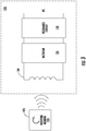
- FIG. 2 is a block diagram illustrating a wireless monitoring system 110 including an energy storage device 130 that is configured for charging via a wireless power transfer device 125 that is wirelessly coupled to a rotating member 106 within the device 105 in some embodiments according to the invention.
- the wireless monitoring system 110 can include a processor circuit that is coupled to the energy storage device 130 to support operations of the wireless monitoring system 110, such as operations of sensors for the collection of data.
- the wireless power transfer device 125 is configured to wirelessly receive the changing magnetic field 107 generated by the rotating member 106, which can be used to induce a current to charge the energy storage device 130 so that the wireless monitoring system 110 may operate under control of the processor circuit. In operation, the wireless power transfer device 125 can immediately begin charging the energy storage device 130 responsive to operation of the device 105. In some embodiments, the processor circuit may receive the induced current/voltage directly so that operations of the wireless monitoring system may begin while the energy storage device 130 is also charged.
- the energy storage device 130 may be charged under the control of the processor circuit.
- the processor circuit may receive the power generated by the wireless power transfer device 125, whereupon the processor circuit controls charging of the energy storage device 130.
- the energy storage device 130 may be any device which can store charge in response to the changing magnetic field 107 received by the wireless power transfer device 125.
- the wireless power transfer device 125 may include an indicator 114, such as a light that provides an indication that the changing magnetic field 107 received by the wireless power transfer device 125 is greater than or equal to a predetermined level so that operations of the wireless monitoring system 110 may be supported.
- an indicator 114 such as a light that provides an indication that the changing magnetic field 107 received by the wireless power transfer device 125 is greater than or equal to a predetermined level so that operations of the wireless monitoring system 110 may be supported.
- the indication device 114 can provide visual feedback to a technician when positioning the wireless power transfer device outside the device 105.
- the visual indication may be provided when, for example, the current induced in the wireless power transfer device 125 is sufficient to charge the energy storage device 130 so that the processor circuit may maintain operations of the wireless monitoring system 110.
- indication device 114 can be any device that provides an indication that the wireless power transfer is sufficient to support charging of the energy storage device 130.
- the indication device 114 can be an audio indication device, a visual indication device, a tactile indication device, or the like.
- the rotating member 106 can be any structure within the device 105 which generates the changing magnetic field 107.
- the rotating member may be a magnetic core material wound with a wire to provide a rotating coil to generate the changing magnetic field 107.
- rotating member 106 can be a permanent magnet that generates the changing magnetic field 107 to support wireless power transfer to the wireless power transfer device 125.
- the rotating member 106 can rotate at a fixed frequency or a viable frequency when, for example, the device 105 is a variable speed motor.
- FIG 3 is a block diagram of a wireless power transfer device 125 configured to wirelessly couple to the device 105 for reception of the changing magnetic field 107 to generate DC current/voltage for charging the energy storage device 130 in some embodiments according to the invention.
- the rotating member 106 wirelessly couples the changing magnetic field 107 to a coil 129 to generate an alternating current I in the coil 129 and an alternating voltage V across the coil 129 (hereinafter referred to as the induced current/voltage).
- the coil 129 can be a conductor that is wound so that when the change in magnetic field 107 is brought into proximity with the coil 129, the induced current/voltage is generated.
- the coil 129 is wound around a core material, such as a ferromagnetic material.
- the coil 129 may have no core (e.g., an airspace) or may include other non- ferromagnetic materials.
- multiple cores 129 can be coupled together to provide increased induced current/voltage. Any type of inductor may be used for the coil 129.
- the induced current/voltage are provided to a rectifier circuit 135 which provides a rectified voltage/current which may be provided for charging the energy storage device 130.
- the coil 129 and components in the rectifier 135 can be passive circuits which do not require external power supplies for operation so that the induced current/voltage can be provided to the energy storage device 130 upon operation of the device 105.
- charging of the energy storage device 130 may commence once the rotating member 106 begins rotating, which may not require operation of the processor circuit for charging of the energy storage device 130 to begin.
- the output of the rectifier circuit 135 can be coupled to a resonance circuit 140 which can be provided in a default configuration to provide resonance at a particular frequency that is associated with the rotational frequency of the rotating member 106.
- the resonance circuit 140 can operate under the control of the processor circuit.
- the resonance circuit 140 may be have a default configuration for a particular frequency of rotation associated with the rotating member 106 such that maximum power transfer can be provided by the wireless power transfer device 125.
- the processor circuit may change the configuration of the resonance circuit 140 to compensate for a change in the rotational frequency of the rotating member 106, such as when the device 105 is a variable speed motor. Other types of devices may also be utilized where the frequency of the rotating member changes or when the processor circuit.
- FIG 4 is a block diagram of a wireless monitoring system including a processor circuit 150 configured to manage charging of the energy storage device 130 using the wireless power transfer device 125 and a switch 145 in some embodiments according to the invention.
- the wireless power transfer device 125 is wirelessly coupled to the rotating member 106 housed within the device 105 to generate a DC current/voltage to the switch 145.
- the processor circuit 150 is also configured to adjust the resonance circuit of the wireless power transfer device as described above in reference to Figure 3 .
- the processor circuit 150 is also configured to control the setting of the switch 145 using a control signal.
- the control signal is configured to switch the DC current/voltage to the processor circuit 150 to charge the energy storage device 130.
- the processor circuit 150 can divert the DC current/voltage to a second input of the processor circuit that is configured to determine the level of the DC voltage.
- diverting the DC voltage to the second input of the processor circuit 150 can isolate the DC voltage from the energy storage device 130 so that the processor circuit 150 can determine the level of the voltage without a significant load.
- the processor circuit 150 may first divert how the DC voltage to the second input to determine whether a threshold value for the DC voltage has been met before beginning to charge the energy storage device 130.
- control signal shown in Figure 4 can also provide control over the switch 145 as described herein.
- the DC voltage provided to the processor circuit 150 can be applied across a filter capacitor 146 which in turn is then applied to the energy storage device 130.
- the processor circuit 150 can control the charging of the energy storage device 130 based on the determined level of charge present in the energy storage device 130. For example, the processor circuit 150 may determine that the energy storage device 130 is fully charged and therefore divert the DC voltage away from the input used for charging and instead provides the DC voltage to the alternative load, such as a second energy storage device or directly to a power supply input of a circuit.
- the processor circuit 150 can also include an interface to a plurality of sensors as described above in reference to Figure 1 as well as provide communications for transmissions of the operating parameters associated with the device 105 to the network 115 as described for example in reference to Figure 1 .
- the wireless power transfer device 125 can be wirelessly coupled to a changing magnetic field that is generated from an AC line 405 that located proximate to the wireless power transfer device.
- the AC line 405 can generate the changing magnetic field when, for example, the energy storage device 130 is fully depleted due to the rotating member 106 being dormant for an extended of time.
- the PMIC 150 can control the wireless power transfer device to resume wirelessly coupling the rotating member 106 to the wireless power transfer device 125 for further charging of the energy storage device 130.
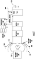
- Figure 5 is a block diagram of a wireless monitoring system 110 including a second processor circuit 160 configured to manage operation of a plurality of sensors 165 and the processor circuit 150 configured to charge the energy storage device 130 in some embodiments according to the invention.
- the coil 129 included in the wireless power transfer device 125 is coupled to focusing magnets 155 that are configured to redirect portions 108 of the magnetic field 107 to the coil 129 to boost the induced current/voltage provided to the rectifier circuit 135.
- the focusing magnets 155 can increase the magnetic field at the coil 129 to increase the induced current/voltage.
- the rectifier circuit 135 can provide greater DC current/voltage to the switch 145.
- the processor circuit 150 can control the state of the switch 145 to either direct the DC current/voltage to the processor circuit 150 to charge the energy storage device 130 or divert the DC current/voltage to the second processor 160 which may determine the level of the voltage provided at the coil 130.
- the focusing magnets 155 can be re-positioned to interactively redirect the portions 108 of the magnetic field during installation so that sufficient wireless power transfer can occur. It will be understood that the adjustments made to the focusing magnets can be made in conjunction with the indicator device 114 so that the technician can adjust the focusing magnets using the feedback from the indicator device 114.
- the second processor circuit 160 can also control operations of the processor circuit 150. For example, in some embodiments according to the invention, when the second processor circuit 160 is communicating with the network 115, the second processor circuit 160 can instruct the processor circuit 150 to stop charging the energy storage device 130 until communications are complete. In still further embodiments according to the invention, the second processor circuit 160 can control the switch 145 (either directly or via the processor circuit 150) to route the DC voltage to an Analog to Digital Converter (ADC) input of the second processor circuit 160 to determine the level of the DC voltage. Once the level of the DC voltage provided by the switch 145 meets a particular threshold, however, the second processor circuit 160 can switch the DC voltage to the processor circuit 150 for control over charging the energy storage device. As further shown in Figure 5 , the second processor circuit 160 can also distribute power to other components included in the wireless monitoring system 110.
- ADC Analog to Digital Converter
- Figure 6 is a schematic illustration of the device 105 including a rotating member 106 configured to generate the magnetic field 107 that is wirelessly coupled to the wireless monitoring system 110 located on the housing 107 of the device 105.
- Figure 7 is a schematic illustration of the device 105 including the rotating member 106 that generates the magnetic field 107 that is wirelessly coupled to the wireless power transfer device 125.
- the wireless power transfer device 125 is located outside the housing 107 proximate to the rotating member 106 so to receive a sufficient level of the magnetic field 107 from the rotating member 106. Still further as shown in Figure 7 , the wireless power transfer circuit 125 may be separate from the remainder of the components in the wireless monitoring system 110.
- the wireless power transfer device 125 may be located nearer to the device 105, whereas the remainder of the components included in the wireless monitoring system 110 may be located elsewhere for ease and installation. Accordingly, the wireless power transfer device 125 may be removably coupled to the remainder of the wireless monitoring system 110 by a connector. Still further, the wireless power transfer device 125 may be utilized to derive energy from the magnetic field to provide power to systems other than the wireless monitoring system 110 as described herein.
- aspects of the present disclosure may be illustrated and described herein in any of a number of patentable classes or contexts including any new and useful process, machine, manufacture, or composition of matter, or any new and useful improvement thereof. Accordingly, aspects of the present disclosure may be implemented entirely hardware, entirely software (including firmware, resident software, micro-code, etc.) or combining software and hardware implementation that may all generally be referred to herein as a "circuit,” “module,” “component,” or “system.” Furthermore, aspects of the present disclosure may take the form of a computer program product comprising one or more computer readable media having computer readable program code embodied thereon.
Landscapes
- Engineering & Computer Science (AREA)
- Power Engineering (AREA)
- Microelectronics & Electronic Packaging (AREA)
- Computer Networks & Wireless Communication (AREA)
- Remote Sensing (AREA)
- Physics & Mathematics (AREA)
- Life Sciences & Earth Sciences (AREA)
- Electromagnetism (AREA)
- Environmental & Geological Engineering (AREA)
- Geology (AREA)
- General Life Sciences & Earth Sciences (AREA)
- General Physics & Mathematics (AREA)
- Geophysics (AREA)
- Charge And Discharge Circuits For Batteries Or The Like (AREA)
Description
- The present inventive concept relates to the field of power in general and, more specifically, to wireless power transfer.
- It is known to the use sensors with devices such as motors to collect operational data. The collected operational data may then be transmitted to a remote server for storage and/or analysis. For example, it is known to attach a vibration sensor to a motor and collect vibration data as the motor operates. The vibration data can be stored by a processor circuit that is proximate to the motor and then transmitted to a remote server for storage and/or analysis. The vibration data can be used to determine the condition of the motor which may be used to predict when the motor may require service or fail.
-
US 2008/252446 A1 discloses an RFID power assisted tag to be mounted on the housing of a motor. The tag comprises a harvesting coil where a current is to be induced by the electromagnetic field generated by the motor in operation. That current is processed by a rectifier and power conditioner unit, constructed to allow for some amount of residual power after the motor is de-energized. -
US 2004/078662 A1 discloses a wireless sensing node to be attached to a rotating machinery and equipped with a piezoelectric transducer as harvesting component and further including a DC-DC converter for interfacing a long-term storage device like a large capacitor or a battery. -
WO 2012/099965 A2 deals with arrangements for modifying the magnitude and phase of an electromagnetic field for use in wireless charging or wireless powering of devices, wherein magnetic flux is guided and is directed to the receiver location by the presence of a receiver magnet. - In a first aspect, the invention is directed to the method for charging an energy storage of
claim 1. In a second aspect, the invention is directed to the apparatus ofclaim 10. - Embodiments according to the invention can provide methods, circuits and systems for operating sensor packages using wireless power transfer derived from rotating members. Pursuant to these embodiments, a method of charging an energy storage device can be provided by wirelessly coupling to a rotating member contained in a housing using a coil attached to an exterior of the housing and charging an energy storage device using a current induced in the coil.
- In some embodiments, an apparatus can include a coil configured to wirelessly couple to a rotating member, the rotating member contained in a housing and the coil configured to attach to an exterior of the housing and an energy storage device coupled to the coil and configured to store energy responsive to a current induced in the coil.
- In some embodiments, an apparatus for charging can include a coil configured to wirelessly couple to a rotating member, where the rotating member is contained in a housing and the coil configured to attach to an exterior of the housing. A rectifier circuit can be coupled to the coil, and the rectifier circuit can be configured to rectify a voltage and a current induced in the coil to provide a rectified current and voltage. A switch can be configured to switch the rectified current and voltage to a charging output of the switch or to a monitor output of the switch responsive to a state of a control signal to the switch and an energy storage device can be coupled to the charging output of the switch and configured to storage charge responsive to the rectified current and voltage.
-
-
Figure 1 is a schematic illustration of a plurality of devices with associated wireless monitoring systems connected to a network utilized to transmit and receive data to an endpoint for data collection and/or analysis in some embodiments according to the invention. -
Figure 2 is a block diagram illustrating a wireless monitoring system including an energy storage device and a wireless power transfer device wirelessly coupled to a rotating member of the device in some embodiments according to the invention. -
Figure 3 is a block diagram of a wireless power transfer device wirelessly coupled to a rotating member in the device in some embodiments according to the invention. -
Figure 4 is a block diagram illustrating a wireless monitoring system including a processor circuit configured to manage charging of an energy storage device and coupled to a wireless power transfer device via a switch in some embodiments according to the invention. -
Figure 5 is a block diagram of a wireless monitoring system operated by a processor circuit configured to control the charging of an energy storage device coupled to a wireless power transfer device that includes focusing magnets in some embodiments according to the invention. -
Figure 6 is a schematic illustration of a device including a rotating member wirelessly coupled to a wireless monitoring system located outside a housing of the device in some embodiments according to the invention. -
Figure 7 is a block diagram illustrating a device including a rotating member that is wirelessly coupled to a wireless power transfer device separate from a processor circuit and configured to transmit data collected by monitoring the device via the wireless power transfer device in some embodiments according to the invention. - Specific exemplary embodiments of the inventive subject matter now will be described with reference to the accompanying drawings. This inventive subject matter may, however, be embodied in many different forms and should not be construed as limited to the embodiments set forth herein; rather, these embodiments are provided so that this disclosure will be thorough and complete, and will fully convey the scope of the inventive subject matter to those skilled in the art. In the drawings, like numbers refer to like elements. It will be understood that when an element is referred to as being "connected" or "coupled" to another element, it can be directly connected or coupled to the other element or intervening elements may be present. As used herein the term "and/or" includes any and all combinations of one or more of the associated listed items.
-
Figure 1 is a schematic illustration of a plurality ofdevices 105 each having a respectivewireless monitoring system 110 configured to communicate with anetwork 115 over which sensor data can be transmitted to anendpoint 120 in some embodiments according to the invention. According toFigure 1 , each of thedevices 105 can include a rotating member that generates a changing magnetic field that is wirelessly coupled to thewireless monitoring system 110. Thewireless monitoring system 110 can include a plurality of sensors that are configured to measure operating parameters associated withdevice 105. For example, in some embodiments according to the invention, operating parameters can include vibration (i.e. movement), temperature, magnetic flux associated with the device, on/off time, and noise. Other operating parameters may also be monitored in some embodiments according to the invention. It will be further understood that the device can be, for example, any type of motor or other device that generates a changing magnetic field that is capable of inducing sufficient current to charge an energy storage device - The
wireless monitoring system 110 can be located outside a housing of thedevice 105 and can be configured for installation after thedevice 105 is deployed. For example, thewireless monitoring system 110 can be installed on or nearby apre-existing device 105, such as a motor, so that thewireless monitoring system 110 can wirelessly couple to a rotating member inside thedevice 105. It will be understood, however, that in some embodiments according to the invention, thewireless monitoring system 110 and thedevice 105 can be installed together. In still other embodiments according to the invention, thewireless monitoring system 110 can be integrated with thedevice 105. - As appreciated by the present inventors, the rotating member in the
device 105 can generate a magnetic field that can be used to wirelessly charge an energy storage device that powers thewireless monitoring system 110. For example, in some embodiments according to the invention, thedevice 105 can be an induction motor that includes a coil wrapped around a core. When the induction motor operates, the rotating coil/core (i.e., rotating member) generates a changing magnetic field (sometimes referred to herein as a magnetic field) that wirelessly couples to the wireless power transfer device to charge the energy storage device which can power thewireless monitoring system 110 for data collection and transmission/reception of data to theendpoint 120 over thenetwork 115. - It will be understood that the
device 105 can be any device which includes a rotating member that generates a changing magnetic field that can be used to wirelessly charge the energy storage device that powers thewireless monitoring system 110. Accordingly, thewireless monitoring system 110 can use a rechargeable energy storage device, such as a supercapacitor or rechargeable battery, so that thewireless monitoring system 110 may be in service longer than would otherwise be possible with a non-rechargeable energy storage device. For example, as appreciated by the present inventors, a non- rechargeable energy storage device may require that the entirewireless monitoring system 110 be replaced when the associated non-rechargeable energy storage device is depleted. - In contrast, in some embodiments according to the invention, the
wireless monitoring system 110 can receive the changing magnetic field generated by the rotating member, and the charge resulting from the current induced in the wireless power transfer device can be stored in the rechargeable energy storage device, which can enable thewireless monitoring system 110 to operate for a longer time period. The extended operating time provided by the rechargeable energy storage device can enable longer/more reliable data collection on thedevice 105 and reduce costs by, for example, avoiding replacement of thewireless monitoring system 110 due to battery depletion (and associated installation costs). Moreover, longer operating time can enable the collection of more operating data on thedevice 105, which can increase improve reliability calculations and/or increase revenue derived from subscriptions to collected data. - As further shown in
Figure 1 , thewireless monitoring system 110 can transmit the collected data associated with thedevice 105 over thenetwork 115. It will be understood that thenetwork 115 can be any type of network or collection of networks that supports ad-hoc interconnection of thewireless monitoring systems 110 to thenetwork 115, such as a Bluetooth network, Wi-Fi, LoRa, FlexNet, Dual LTE-M. Other types of networks may be used. Accordingly, the wireless monitoring system may wirelessly connect to thenetwork 115 without user intervention and may receive remote instructions via thenetwork 115. Still further, thewireless monitoring system 110 can be configured to transmit the collected data over thenetwork 115 to theremote endpoint 120. It will be understood that thesystem 100 can include otherremote endpoints 120. - It will be understood that the
remote endpoint 120 can be a server that provides storage of the collected data for later analysis. The server may, for example, provide remote users with access to aggregated data collected on a particular device type, a particular class of devices, or any other organization of data collected on associated devices. The remote users may analyze the collected data to derive an understanding of the operations of that particular device, a particular class of devices, or the like. - In still further embodiments according to the invention, the
system 100 can be included as a part of a subscription service whereby a party, such as an operator of thedevices 105 or service organization responsible for maintaining thedevices 105, can subscribe to data collection via thewireless monitoring system 110. For example, in an Internet Of Things (IoT) ecosystem, an operator of the devices 105 (such as an operator of manufacturing plants) may deploy a large number of thewireless monitoring systems 110 which may collect data related to the operations ofrespective devices 105. A subscriber of data may contract to receive the data collected on thosedevices 105, so that the subscriber receives information regarding operations of thedevices 105. In still further embodiments according to the invention, the subscriber may be a manufacturer of certain ones of thedevices 105 and may utilize the collected data for reliability analysis of thedevices 105 or to provide field service support for thosedevices 105. In some embodiments, the subscriber may be a third party that aggregates the data for analysis by other parties. It will be further understood that the data collected via thenetwork 115 can span a large number of different operators and a wide variety ofdevices 105, which can also be included as part of the collected data, such as hours of operation, geographic location, ambient temperatures, associated with the environment in which thedevices 105 operate. - Furthermore, in the IoT ecosystem, the
wireless monitoring system 110 can be part of a subscription service whereby a subscriber can receive particular types of data from selected ones of thedevices 105 in a secure and frictionless transaction. For example, in an IoT ecosystem supported by blockchain technology, the subscriber may deploy a system that communicates with certain ones of thedevices 105 for receipt of particular operating parameters associated therewith. In operation, the subscription system would, for example, conduct transactions to receive the operating data without the need for subscriber intervention. Still further, the operator, owner of thewireless monitoring system 110, or other party can receive revenue from the subscriber. -
Figure 2 is a block diagram illustrating awireless monitoring system 110 including anenergy storage device 130 that is configured for charging via a wirelesspower transfer device 125 that is wirelessly coupled to a rotatingmember 106 within thedevice 105 in some embodiments according to the invention. According toFigure 2 , it will be understood that thewireless monitoring system 110 can include a processor circuit that is coupled to theenergy storage device 130 to support operations of thewireless monitoring system 110, such as operations of sensors for the collection of data. - The wireless
power transfer device 125 is configured to wirelessly receive the changingmagnetic field 107 generated by the rotatingmember 106, which can be used to induce a current to charge theenergy storage device 130 so that thewireless monitoring system 110 may operate under control of the processor circuit. In operation, the wirelesspower transfer device 125 can immediately begin charging theenergy storage device 130 responsive to operation of thedevice 105. In some embodiments, the processor circuit may receive the induced current/voltage directly so that operations of the wireless monitoring system may begin while theenergy storage device 130 is also charged. - It will be understood that in some embodiments according to the invention, the
energy storage device 130 may be charged under the control of the processor circuit. In such embodiments, the processor circuit may receive the power generated by the wirelesspower transfer device 125, whereupon the processor circuit controls charging of theenergy storage device 130. It will further be understood that theenergy storage device 130 may be any device which can store charge in response to the changingmagnetic field 107 received by the wirelesspower transfer device 125. - As further shown in
Figure 2 , the wirelesspower transfer device 125 may include an indicator 114, such as a light that provides an indication that the changingmagnetic field 107 received by the wirelesspower transfer device 125 is greater than or equal to a predetermined level so that operations of thewireless monitoring system 110 may be supported. For example, in some embodiments according to the invention, during installation the indication device 114 can provide visual feedback to a technician when positioning the wireless power transfer device outside thedevice 105. The visual indication may be provided when, for example, the current induced in the wirelesspower transfer device 125 is sufficient to charge theenergy storage device 130 so that the processor circuit may maintain operations of thewireless monitoring system 110. If the technician observes that there is no visual indication, however, the technician may be prompted to relocate the wirelesspower transfer device 125 relative to the rotatingmember 106 until a visual indication is provided. The technician may then fix the wirelesspower transfer device 125 in that location where themagnetic field 107 received from the rotatingmember 106 is sufficient. Accordingly, the technician may be assured that the installation is properly configured to receive sufficient wireless power transfer so that thewireless monitoring system 110 may operate reliably. It will be further understood that indication device 114 can be any device that provides an indication that the wireless power transfer is sufficient to support charging of theenergy storage device 130. For example, the indication device 114 can be an audio indication device, a visual indication device, a tactile indication device, or the like. - It will be further understood that the rotating
member 106 can be any structure within thedevice 105 which generates the changingmagnetic field 107. For example, in some embodiments according to the invention, the rotating member may be a magnetic core material wound with a wire to provide a rotating coil to generate the changingmagnetic field 107. In still further embodiments according to the invention, rotatingmember 106 can be a permanent magnet that generates the changingmagnetic field 107 to support wireless power transfer to the wirelesspower transfer device 125. In still further embodiments according to the invention, the rotatingmember 106 can rotate at a fixed frequency or a viable frequency when, for example, thedevice 105 is a variable speed motor. -
Figure 3 is a block diagram of a wirelesspower transfer device 125 configured to wirelessly couple to thedevice 105 for reception of the changingmagnetic field 107 to generate DC current/voltage for charging theenergy storage device 130 in some embodiments according to the invention. According toFigure 3 , the rotatingmember 106 wirelessly couples the changingmagnetic field 107 to acoil 129 to generate an alternating current I in thecoil 129 and an alternating voltage V across the coil 129 (hereinafter referred to as the induced current/voltage). It will be understood that thecoil 129 can be a conductor that is wound so that when the change inmagnetic field 107 is brought into proximity with thecoil 129, the induced current/voltage is generated. In some embodiments according to the invention, thecoil 129 is wound around a core material, such as a ferromagnetic material. In some embodiments according to the invention, thecoil 129 may have no core (e.g., an airspace) or may include other non- ferromagnetic materials. In some embodiments,multiple cores 129 can be coupled together to provide increased induced current/voltage. Any type of inductor may be used for thecoil 129. - The induced current/voltage are provided to a
rectifier circuit 135 which provides a rectified voltage/current which may be provided for charging theenergy storage device 130. It will be understood that thecoil 129 and components in therectifier 135 can be passive circuits which do not require external power supplies for operation so that the induced current/voltage can be provided to theenergy storage device 130 upon operation of thedevice 105. In other words, in some embodiments according to the invention, charging of theenergy storage device 130 may commence once the rotatingmember 106 begins rotating, which may not require operation of the processor circuit for charging of theenergy storage device 130 to begin. - In still further embodiments according to the invention as shown in
Figure 3 , the output of therectifier circuit 135 can be coupled to aresonance circuit 140 which can be provided in a default configuration to provide resonance at a particular frequency that is associated with the rotational frequency of the rotatingmember 106. In still further embodiments according to the invention, theresonance circuit 140 can operate under the control of the processor circuit. In operation, theresonance circuit 140 may be have a default configuration for a particular frequency of rotation associated with the rotatingmember 106 such that maximum power transfer can be provided by the wirelesspower transfer device 125. In operation, however, the processor circuit may change the configuration of theresonance circuit 140 to compensate for a change in the rotational frequency of the rotatingmember 106, such as when thedevice 105 is a variable speed motor. Other types of devices may also be utilized where the frequency of the rotating member changes or when the processor circuit. -
Figure 4 is a block diagram of a wireless monitoring system including aprocessor circuit 150 configured to manage charging of theenergy storage device 130 using the wirelesspower transfer device 125 and aswitch 145 in some embodiments according to the invention. According toFigure 4 , the wirelesspower transfer device 125 is wirelessly coupled to the rotatingmember 106 housed within thedevice 105 to generate a DC current/voltage to theswitch 145. As further shown inFigure 4 , theprocessor circuit 150 is also configured to adjust the resonance circuit of the wireless power transfer device as described above in reference toFigure 3 . - The
processor circuit 150 is also configured to control the setting of theswitch 145 using a control signal. In a first state, the control signal is configured to switch the DC current/voltage to theprocessor circuit 150 to charge theenergy storage device 130. In a second state, theprocessor circuit 150 can divert the DC current/voltage to a second input of the processor circuit that is configured to determine the level of the DC voltage. In some embodiments according to the invention, diverting the DC voltage to the second input of theprocessor circuit 150 can isolate the DC voltage from theenergy storage device 130 so that theprocessor circuit 150 can determine the level of the voltage without a significant load. In operation, theprocessor circuit 150 may first divert how the DC voltage to the second input to determine whether a threshold value for the DC voltage has been met before beginning to charge theenergy storage device 130. - It will be understood that the control signal shown in
Figure 4 can also provide control over theswitch 145 as described herein. Still further as shown inFigure 4 , the DC voltage provided to theprocessor circuit 150 can be applied across a filter capacitor 146 which in turn is then applied to theenergy storage device 130. In operation, theprocessor circuit 150 can control the charging of theenergy storage device 130 based on the determined level of charge present in theenergy storage device 130. For example, theprocessor circuit 150 may determine that theenergy storage device 130 is fully charged and therefore divert the DC voltage away from the input used for charging and instead provides the DC voltage to the alternative load, such as a second energy storage device or directly to a power supply input of a circuit. Theprocessor circuit 150 can also include an interface to a plurality of sensors as described above in reference toFigure 1 as well as provide communications for transmissions of the operating parameters associated with thedevice 105 to thenetwork 115 as described for example in reference toFigure 1 . - As further shown in
Figure 4 , in some embodiments, the wirelesspower transfer device 125 can be wirelessly coupled to a changing magnetic field that is generated from anAC line 405 that located proximate to the wireless power transfer device. In such embodiments, theAC line 405 can generate the changing magnetic field when, for example, theenergy storage device 130 is fully depleted due to the rotatingmember 106 being dormant for an extended of time. Still further, once theenergy storage device 130 is partially charged via theAC line 405, thePMIC 150 can control the wireless power transfer device to resume wirelessly coupling the rotatingmember 106 to the wirelesspower transfer device 125 for further charging of theenergy storage device 130. -
Figure 5 is a block diagram of awireless monitoring system 110 including asecond processor circuit 160 configured to manage operation of a plurality ofsensors 165 and theprocessor circuit 150 configured to charge theenergy storage device 130 in some embodiments according to the invention. According toFigure 5 , thecoil 129 included in the wirelesspower transfer device 125 is coupled to focusingmagnets 155 that are configured to redirectportions 108 of themagnetic field 107 to thecoil 129 to boost the induced current/voltage provided to therectifier circuit 135. - As appreciated by the present inventors, the focusing
magnets 155 can increase the magnetic field at thecoil 129 to increase the induced current/voltage. In turn, therectifier circuit 135 can provide greater DC current/voltage to theswitch 145. In operation, theprocessor circuit 150 can control the state of theswitch 145 to either direct the DC current/voltage to theprocessor circuit 150 to charge theenergy storage device 130 or divert the DC current/voltage to thesecond processor 160 which may determine the level of the voltage provided at thecoil 130. In some embodiments, the focusingmagnets 155 can be re-positioned to interactively redirect theportions 108 of the magnetic field during installation so that sufficient wireless power transfer can occur. It will be understood that the adjustments made to the focusing magnets can be made in conjunction with the indicator device 114 so that the technician can adjust the focusing magnets using the feedback from the indicator device 114. - In some embodiments, the
second processor circuit 160 can also control operations of theprocessor circuit 150. For example, in some embodiments according to the invention, when thesecond processor circuit 160 is communicating with thenetwork 115, thesecond processor circuit 160 can instruct theprocessor circuit 150 to stop charging theenergy storage device 130 until communications are complete. In still further embodiments according to the invention, thesecond processor circuit 160 can control the switch 145 (either directly or via the processor circuit 150) to route the DC voltage to an Analog to Digital Converter (ADC) input of thesecond processor circuit 160 to determine the level of the DC voltage. Once the level of the DC voltage provided by theswitch 145 meets a particular threshold, however, thesecond processor circuit 160 can switch the DC voltage to theprocessor circuit 150 for control over charging the energy storage device. As further shown inFigure 5 , thesecond processor circuit 160 can also distribute power to other components included in thewireless monitoring system 110. -
Figure 6 is a schematic illustration of thedevice 105 including a rotatingmember 106 configured to generate themagnetic field 107 that is wirelessly coupled to thewireless monitoring system 110 located on thehousing 107 of thedevice 105.Figure 7 is a schematic illustration of thedevice 105 including the rotatingmember 106 that generates themagnetic field 107 that is wirelessly coupled to the wirelesspower transfer device 125. In some embodiments according to the invention, the wirelesspower transfer device 125 is located outside thehousing 107 proximate to the rotatingmember 106 so to receive a sufficient level of themagnetic field 107 from the rotatingmember 106. Still further as shown inFigure 7 , the wirelesspower transfer circuit 125 may be separate from the remainder of the components in thewireless monitoring system 110. Accordingly, in some embodiments according to the invention, the wirelesspower transfer device 125 may be located nearer to thedevice 105, whereas the remainder of the components included in thewireless monitoring system 110 may be located elsewhere for ease and installation. Accordingly, the wirelesspower transfer device 125 may be removably coupled to the remainder of thewireless monitoring system 110 by a connector. Still further, the wirelesspower transfer device 125 may be utilized to derive energy from the magnetic field to provide power to systems other than thewireless monitoring system 110 as described herein. - The terminology used herein is for the purpose of describing particular embodiments only and is not intended to be limiting of the inventive subject matter. As used herein, the singular forms "a", "an" and "the" are intended to include the plural forms as well, unless expressly stated otherwise. It will be further understood that the terms "includes," "comprises," "including" and/or "comprising," when used in this specification, specify the presence of stated features, integers, steps, operations, elements, and/or components, but do not preclude the presence or addition of one or more other features, integers, steps, operations, elements, components, and/or groups thereof.
- Unless otherwise defined, all terms (including technical and scientific terms) used herein have the same meaning as commonly understood by one of ordinary skill in the art to which this inventive subject matter belongs. It will be further understood that terms, such as those defined in commonly used dictionaries, should be interpreted as having a meaning that is consistent with their meaning in the context of the specification and the relevant art and will not be interpreted in an idealized or overly formal sense unless expressly so defined herein.
- As will be appreciated by one skilled in the art, aspects of the present disclosure may be illustrated and described herein in any of a number of patentable classes or contexts including any new and useful process, machine, manufacture, or composition of matter, or any new and useful improvement thereof. Accordingly, aspects of the present disclosure may be implemented entirely hardware, entirely software (including firmware, resident software, micro-code, etc.) or combining software and hardware implementation that may all generally be referred to herein as a "circuit," "module," "component," or "system." Furthermore, aspects of the present disclosure may take the form of a computer program product comprising one or more computer readable media having computer readable program code embodied thereon.
- In the drawings and specification, there have been disclosed exemplary embodiments of the inventive subject matter. Although specific terms are employed, they are used in a generic and descriptive sense only and not for purposes of limitation, the scope of the inventive subject matter being defined by the following claims.
Claims (14)
- A method of charging an energy storage device (130), the method comprising:wirelessly coupling to a rotating member (106) contained in a housing using a coil (129) attached to an exterior of the housing;charging an energy storage device (130) using a current induced in the coil (129) during rotation of the rotating member (106) in response to a request for charging the energy storage device; andswitching to charging of the energy storage device (130) based on wirelessly coupling to a changing magnetic field from an AC line (405) used to power the rotating member (106), responsive to the rotating member (106) being dormant for an extended period.
- The method of Claim 1 wherein the rotating member (106) comprises a rotating coil.
- The method of Claim 1 wherein the rotating member (106) comprises a rotating permanent magnet.
- The method of Claim 1 wherein the coil (129) is wound around a magnetic core.
- The method of Claim 1 further comprising:
determining an indication of a magnetic flux associated with the rotating member (106) based on the current. - The method of Claim 1 further comprising:rectifying a voltage associated with the current to provide a rectified voltage;switching the rectified voltage to a circuit (150) configured to determine a magnitude of the rectified voltage when isolated from other loads responsive to a control signal in a first state; andswitching the rectified voltage to the energy storage device (130) for charging responsive to a control signal in a second state.
- The method of Claim 6 wherein the second state indicates that the magnitude of the rectified voltage is above a threshold value sufficient for charging the energy storage device (130).
- The method of Claim 6 wherein the second state indicates the request for charging the energy storage device (130).
- The method of Claim 6 wherein the first state indicates the request to suspend charging of the energy storage device (130).
- An apparatus comprising:a coil (129) configured to wirelessly couple to a rotating member (106), the rotating member contained in a housing and the coil configured to attach to an exterior of the housing;an energy storage device (130) coupled to the coil (129) and configured to store energy responsive to a current induced in the coil by rotation of the rotating member (106); anda processor circuit (150) configured to receive charge state information of the energy storage device (130) and to transmit a command configured to enable charging of the energy storage device (130) or to disable charging of the energy storage device (130) and enable charging of the energy storage device (130) based on wirelessly coupling to a changing magnetic field from an AC line (405) used to power the rotating member (106), responsive to the rotating member (106) being dormant for an extended period.
- The apparatus of Claim 10 wherein the rotating member (106) comprises a rotating coil.
- The apparatus of Claim 10 wherein the rotating member (106) comprises a rotating permanent magnet.
- The apparatus of Claim 10 wherein the apparatus further comprises a magnetic core and the coil (129) is wound around the magnetic core.
- The apparatus of Claim 10 further comprising:
at least one focusing magnet (155) wirelessly coupled to an end of the coil (129), wherein the focusing magnet (155) is configured to redirect portions (108) of a magnetic field (107) generated by the rotating member (106) toward an interior of the coil (129).
Applications Claiming Priority (2)
| Application Number | Priority Date | Filing Date | Title |
|---|---|---|---|
| US15/800,658 US10910863B2 (en) | 2017-11-01 | 2017-11-01 | Methods, circuits and systems for operating sensor packages using wireless power transfer derived from rotating members |
| PCT/US2018/058426 WO2019089738A1 (en) | 2017-11-01 | 2018-10-31 | Methods, circuits and systems for operating sensor packages using wireless power transfer derived from rotating members |
Publications (2)
| Publication Number | Publication Date |
|---|---|
| EP3704780A1 EP3704780A1 (en) | 2020-09-09 |
| EP3704780B1 true EP3704780B1 (en) | 2021-09-01 |
Family
ID=64427216
Family Applications (1)
| Application Number | Title | Priority Date | Filing Date |
|---|---|---|---|
| EP18807493.4A Active EP3704780B1 (en) | 2017-11-01 | 2018-10-31 | Method and apparatus for operating sensor packages using wireless power transfer derived from rotating members |
Country Status (4)
| Country | Link |
|---|---|
| US (1) | US10910863B2 (en) |
| EP (1) | EP3704780B1 (en) |
| CA (1) | CA3081433A1 (en) |
| WO (1) | WO2019089738A1 (en) |
Families Citing this family (2)
| Publication number | Priority date | Publication date | Assignee | Title |
|---|---|---|---|---|
| US12357792B2 (en) | 2019-01-04 | 2025-07-15 | Shifamed Holdings, Llc | Internal recharging systems and methods of use |
| WO2021217059A1 (en) | 2020-04-23 | 2021-10-28 | Shifamed Holdings, Llc | Power management for interatrial shunts and associated systems and methods |
Family Cites Families (11)
| Publication number | Priority date | Publication date | Assignee | Title |
|---|---|---|---|---|
| US7081693B2 (en) * | 2002-03-07 | 2006-07-25 | Microstrain, Inc. | Energy harvesting for wireless sensor operation and data transmission |
| US20080252446A1 (en) | 2007-04-16 | 2008-10-16 | Credo Technology Corporation | Power hand tool with data collection and storage and method of operating |
| EP2161811A1 (en) * | 2008-09-05 | 2010-03-10 | Koninklijke Philips Electronics N.V. | Inductive charger and charging method |
| US8378511B2 (en) * | 2008-11-18 | 2013-02-19 | Gary Steven Sichau | Devices and methods for converting wave energy into electricity |
| US9178369B2 (en) | 2011-01-18 | 2015-11-03 | Mojo Mobility, Inc. | Systems and methods for providing positioning freedom, and support of different voltages, protocols, and power levels in a wireless power system |
| KR102096312B1 (en) * | 2013-07-03 | 2020-04-02 | 엘지전자 주식회사 | Wireless power transmitter and method of wireless power transmittion |
| WO2015063534A1 (en) * | 2013-10-30 | 2015-05-07 | Mohamed Hossam Abdel Salam El Sayed | Uni-polar pulsed electromagnetic medical apparatus and methods of use |
| MX2016009933A (en) * | 2014-02-07 | 2017-01-23 | Nidec Motor Corp | Systems, devices, and methods for motor monitoring. |
| US20170194837A1 (en) * | 2014-12-24 | 2017-07-06 | Gary Steven Sichau | Energy conversion systems and methods |
| TWI544718B (en) * | 2015-07-27 | 2016-08-01 | 緯創資通股份有限公司 | Wireless charging device and wireless charging method |
| US10181759B2 (en) * | 2016-09-14 | 2019-01-15 | Qualcomm Incorporated | Dynamic mutual sensing foreign object detection loops |
-
2017
- 2017-11-01 US US15/800,658 patent/US10910863B2/en active Active
-
2018
- 2018-10-31 WO PCT/US2018/058426 patent/WO2019089738A1/en not_active Ceased
- 2018-10-31 CA CA3081433A patent/CA3081433A1/en active Pending
- 2018-10-31 EP EP18807493.4A patent/EP3704780B1/en active Active
Also Published As
| Publication number | Publication date |
|---|---|
| CA3081433A1 (en) | 2019-05-09 |
| EP3704780A1 (en) | 2020-09-09 |
| US10910863B2 (en) | 2021-02-02 |
| WO2019089738A1 (en) | 2019-05-09 |
| US20190131813A1 (en) | 2019-05-02 |
Similar Documents
| Publication | Publication Date | Title |
|---|---|---|
| KR101882754B1 (en) | Method for controlling power trasnmitting in wireless charging device and the wireless charging device therefor | |
| EP3108565B1 (en) | Device detection through dynamic impedance change measurement | |
| Fukuda et al. | A novel metal detector using the quality factor of the secondary coil for wireless power transfer systems | |
| EP2793487B1 (en) | Hearing apparatus including coil operable in different operation modes | |
| JP5177187B2 (en) | Power transmission system | |
| KR101775234B1 (en) | Wireless Power Transfer System and Operating method thereof | |
| EP3425769B1 (en) | Adapting wireless power transfer parameters to transmitter operating conditions | |
| CN109104885A (en) | Wireless charging system and its equipment | |
| US20090015196A1 (en) | Power Supply for Sensors and Other Electronic Devices | |
| US9973030B2 (en) | Wireless charging device | |
| EP2896134A1 (en) | Static tuning of wireless transmitters | |
| US11271432B2 (en) | Wireless power control method and device | |
| US20180316388A1 (en) | Wireless power transmitter, wireless power receiver, and wireless system, for transmitting and receiving wireless signal, and operating method therefor | |
| TW201347345A (en) | Wireless power control system | |
| US20140327381A1 (en) | Motor with rotor-mounted control circuitry | |
| WO2012112703A1 (en) | Systems and methods for controlling output power of a wireless power transmitter | |
| JP2014506111A (en) | System for wireless power transmission | |
| US20160352147A1 (en) | Wireless power transfer using a field altering circuit | |
| WO2023022994A1 (en) | Transmitter coil power foreign object detection | |
| US10910863B2 (en) | Methods, circuits and systems for operating sensor packages using wireless power transfer derived from rotating members | |
| US11374441B2 (en) | Negative modulation solution for fixed coil designs | |
| EP3407461B1 (en) | System and method for wireless charging of a beacon and/or sensor device | |
| CN106471342B (en) | Sensor device and rolling bearing comprising such a sensor device | |
| KR102563553B1 (en) | Efficient wireless power charging apparatus and method thereof | |
| US20220032776A1 (en) | Device and method for supplying energy to a sensor device in a rail vehicle |
Legal Events
| Date | Code | Title | Description |
|---|---|---|---|
| STAA | Information on the status of an ep patent application or granted ep patent |
Free format text: STATUS: UNKNOWN |
|
| STAA | Information on the status of an ep patent application or granted ep patent |
Free format text: STATUS: THE INTERNATIONAL PUBLICATION HAS BEEN MADE |
|
| PUAI | Public reference made under article 153(3) epc to a published international application that has entered the european phase |
Free format text: ORIGINAL CODE: 0009012 |
|
| STAA | Information on the status of an ep patent application or granted ep patent |
Free format text: STATUS: REQUEST FOR EXAMINATION WAS MADE |
|
| 17P | Request for examination filed |
Effective date: 20200430 |
|
| AK | Designated contracting states |
Kind code of ref document: A1 Designated state(s): AL AT BE BG CH CY CZ DE DK EE ES FI FR GB GR HR HU IE IS IT LI LT LU LV MC MK MT NL NO PL PT RO RS SE SI SK SM TR |
|
| AX | Request for extension of the european patent |
Extension state: BA ME |
|
| DAV | Request for validation of the european patent (deleted) | ||
| DAX | Request for extension of the european patent (deleted) | ||
| GRAP | Despatch of communication of intention to grant a patent |
Free format text: ORIGINAL CODE: EPIDOSNIGR1 |
|
| STAA | Information on the status of an ep patent application or granted ep patent |
Free format text: STATUS: GRANT OF PATENT IS INTENDED |
|
| INTG | Intention to grant announced |
Effective date: 20210312 |
|
| GRAS | Grant fee paid |
Free format text: ORIGINAL CODE: EPIDOSNIGR3 |
|
| GRAA | (expected) grant |
Free format text: ORIGINAL CODE: 0009210 |
|
| STAA | Information on the status of an ep patent application or granted ep patent |
Free format text: STATUS: THE PATENT HAS BEEN GRANTED |
|
| AK | Designated contracting states |
Kind code of ref document: B1 Designated state(s): AL AT BE BG CH CY CZ DE DK EE ES FI FR GB GR HR HU IE IS IT LI LT LU LV MC MK MT NL NO PL PT RO RS SE SI SK SM TR |
|
| REG | Reference to a national code |
Ref country code: GB Ref legal event code: FG4D |
|
| REG | Reference to a national code |
Ref country code: CH Ref legal event code: EP Ref country code: AT Ref legal event code: REF Ref document number: 1427246 Country of ref document: AT Kind code of ref document: T Effective date: 20210915 |
|
| REG | Reference to a national code |
Ref country code: DE Ref legal event code: R096 Ref document number: 602018023011 Country of ref document: DE |
|
| REG | Reference to a national code |
Ref country code: IE Ref legal event code: FG4D |
|
| REG | Reference to a national code |
Ref country code: LT Ref legal event code: MG9D |
|
| REG | Reference to a national code |
Ref country code: NL Ref legal event code: MP Effective date: 20210901 |
|
| PG25 | Lapsed in a contracting state [announced via postgrant information from national office to epo] |
Ref country code: RS Free format text: LAPSE BECAUSE OF FAILURE TO SUBMIT A TRANSLATION OF THE DESCRIPTION OR TO PAY THE FEE WITHIN THE PRESCRIBED TIME-LIMIT Effective date: 20210901 Ref country code: SE Free format text: LAPSE BECAUSE OF FAILURE TO SUBMIT A TRANSLATION OF THE DESCRIPTION OR TO PAY THE FEE WITHIN THE PRESCRIBED TIME-LIMIT Effective date: 20210901 Ref country code: ES Free format text: LAPSE BECAUSE OF FAILURE TO SUBMIT A TRANSLATION OF THE DESCRIPTION OR TO PAY THE FEE WITHIN THE PRESCRIBED TIME-LIMIT Effective date: 20210901 Ref country code: FI Free format text: LAPSE BECAUSE OF FAILURE TO SUBMIT A TRANSLATION OF THE DESCRIPTION OR TO PAY THE FEE WITHIN THE PRESCRIBED TIME-LIMIT Effective date: 20210901 Ref country code: LT Free format text: LAPSE BECAUSE OF FAILURE TO SUBMIT A TRANSLATION OF THE DESCRIPTION OR TO PAY THE FEE WITHIN THE PRESCRIBED TIME-LIMIT Effective date: 20210901 Ref country code: BG Free format text: LAPSE BECAUSE OF FAILURE TO SUBMIT A TRANSLATION OF THE DESCRIPTION OR TO PAY THE FEE WITHIN THE PRESCRIBED TIME-LIMIT Effective date: 20211201 Ref country code: HR Free format text: LAPSE BECAUSE OF FAILURE TO SUBMIT A TRANSLATION OF THE DESCRIPTION OR TO PAY THE FEE WITHIN THE PRESCRIBED TIME-LIMIT Effective date: 20210901 Ref country code: NO Free format text: LAPSE BECAUSE OF FAILURE TO SUBMIT A TRANSLATION OF THE DESCRIPTION OR TO PAY THE FEE WITHIN THE PRESCRIBED TIME-LIMIT Effective date: 20211201 |
|
| REG | Reference to a national code |
Ref country code: AT Ref legal event code: MK05 Ref document number: 1427246 Country of ref document: AT Kind code of ref document: T Effective date: 20210901 |
|
| PG25 | Lapsed in a contracting state [announced via postgrant information from national office to epo] |
Ref country code: PL Free format text: LAPSE BECAUSE OF FAILURE TO SUBMIT A TRANSLATION OF THE DESCRIPTION OR TO PAY THE FEE WITHIN THE PRESCRIBED TIME-LIMIT Effective date: 20210901 Ref country code: LV Free format text: LAPSE BECAUSE OF FAILURE TO SUBMIT A TRANSLATION OF THE DESCRIPTION OR TO PAY THE FEE WITHIN THE PRESCRIBED TIME-LIMIT Effective date: 20210901 Ref country code: GR Free format text: LAPSE BECAUSE OF FAILURE TO SUBMIT A TRANSLATION OF THE DESCRIPTION OR TO PAY THE FEE WITHIN THE PRESCRIBED TIME-LIMIT Effective date: 20211202 |
|
| PG25 | Lapsed in a contracting state [announced via postgrant information from national office to epo] |
Ref country code: AT Free format text: LAPSE BECAUSE OF FAILURE TO SUBMIT A TRANSLATION OF THE DESCRIPTION OR TO PAY THE FEE WITHIN THE PRESCRIBED TIME-LIMIT Effective date: 20210901 |
|
| REG | Reference to a national code |
Ref country code: CH Ref legal event code: PL |
|
| PG25 | Lapsed in a contracting state [announced via postgrant information from national office to epo] |
Ref country code: IS Free format text: LAPSE BECAUSE OF FAILURE TO SUBMIT A TRANSLATION OF THE DESCRIPTION OR TO PAY THE FEE WITHIN THE PRESCRIBED TIME-LIMIT Effective date: 20220101 Ref country code: SM Free format text: LAPSE BECAUSE OF FAILURE TO SUBMIT A TRANSLATION OF THE DESCRIPTION OR TO PAY THE FEE WITHIN THE PRESCRIBED TIME-LIMIT Effective date: 20210901 Ref country code: SK Free format text: LAPSE BECAUSE OF FAILURE TO SUBMIT A TRANSLATION OF THE DESCRIPTION OR TO PAY THE FEE WITHIN THE PRESCRIBED TIME-LIMIT Effective date: 20210901 Ref country code: RO Free format text: LAPSE BECAUSE OF FAILURE TO SUBMIT A TRANSLATION OF THE DESCRIPTION OR TO PAY THE FEE WITHIN THE PRESCRIBED TIME-LIMIT Effective date: 20210901 Ref country code: PT Free format text: LAPSE BECAUSE OF FAILURE TO SUBMIT A TRANSLATION OF THE DESCRIPTION OR TO PAY THE FEE WITHIN THE PRESCRIBED TIME-LIMIT Effective date: 20220103 Ref country code: NL Free format text: LAPSE BECAUSE OF FAILURE TO SUBMIT A TRANSLATION OF THE DESCRIPTION OR TO PAY THE FEE WITHIN THE PRESCRIBED TIME-LIMIT Effective date: 20210901 Ref country code: EE Free format text: LAPSE BECAUSE OF FAILURE TO SUBMIT A TRANSLATION OF THE DESCRIPTION OR TO PAY THE FEE WITHIN THE PRESCRIBED TIME-LIMIT Effective date: 20210901 Ref country code: CZ Free format text: LAPSE BECAUSE OF FAILURE TO SUBMIT A TRANSLATION OF THE DESCRIPTION OR TO PAY THE FEE WITHIN THE PRESCRIBED TIME-LIMIT Effective date: 20210901 Ref country code: AL Free format text: LAPSE BECAUSE OF FAILURE TO SUBMIT A TRANSLATION OF THE DESCRIPTION OR TO PAY THE FEE WITHIN THE PRESCRIBED TIME-LIMIT Effective date: 20210901 |
|
| REG | Reference to a national code |
Ref country code: DE Ref legal event code: R097 Ref document number: 602018023011 Country of ref document: DE |
|
| REG | Reference to a national code |
Ref country code: BE Ref legal event code: MM Effective date: 20211031 |
|
| PG25 | Lapsed in a contracting state [announced via postgrant information from national office to epo] |
Ref country code: MC Free format text: LAPSE BECAUSE OF FAILURE TO SUBMIT A TRANSLATION OF THE DESCRIPTION OR TO PAY THE FEE WITHIN THE PRESCRIBED TIME-LIMIT Effective date: 20210901 |
|
| PLBE | No opposition filed within time limit |
Free format text: ORIGINAL CODE: 0009261 |
|
| STAA | Information on the status of an ep patent application or granted ep patent |
Free format text: STATUS: NO OPPOSITION FILED WITHIN TIME LIMIT |
|
| PG25 | Lapsed in a contracting state [announced via postgrant information from national office to epo] |
Ref country code: LU Free format text: LAPSE BECAUSE OF NON-PAYMENT OF DUE FEES Effective date: 20211031 Ref country code: DK Free format text: LAPSE BECAUSE OF FAILURE TO SUBMIT A TRANSLATION OF THE DESCRIPTION OR TO PAY THE FEE WITHIN THE PRESCRIBED TIME-LIMIT Effective date: 20210901 Ref country code: BE Free format text: LAPSE BECAUSE OF NON-PAYMENT OF DUE FEES Effective date: 20211031 |
|
| 26N | No opposition filed |
Effective date: 20220602 |
|
| PG25 | Lapsed in a contracting state [announced via postgrant information from national office to epo] |
Ref country code: SI Free format text: LAPSE BECAUSE OF FAILURE TO SUBMIT A TRANSLATION OF THE DESCRIPTION OR TO PAY THE FEE WITHIN THE PRESCRIBED TIME-LIMIT Effective date: 20210901 Ref country code: LI Free format text: LAPSE BECAUSE OF NON-PAYMENT OF DUE FEES Effective date: 20211031 Ref country code: CH Free format text: LAPSE BECAUSE OF NON-PAYMENT OF DUE FEES Effective date: 20211031 |
|
| PG25 | Lapsed in a contracting state [announced via postgrant information from national office to epo] |
Ref country code: IE Free format text: LAPSE BECAUSE OF NON-PAYMENT OF DUE FEES Effective date: 20211031 |
|
| PG25 | Lapsed in a contracting state [announced via postgrant information from national office to epo] |
Ref country code: CY Free format text: LAPSE BECAUSE OF FAILURE TO SUBMIT A TRANSLATION OF THE DESCRIPTION OR TO PAY THE FEE WITHIN THE PRESCRIBED TIME-LIMIT Effective date: 20210901 |
|
| PG25 | Lapsed in a contracting state [announced via postgrant information from national office to epo] |
Ref country code: HU Free format text: LAPSE BECAUSE OF FAILURE TO SUBMIT A TRANSLATION OF THE DESCRIPTION OR TO PAY THE FEE WITHIN THE PRESCRIBED TIME-LIMIT; INVALID AB INITIO Effective date: 20181031 |
|
| PG25 | Lapsed in a contracting state [announced via postgrant information from national office to epo] |
Ref country code: MK Free format text: LAPSE BECAUSE OF FAILURE TO SUBMIT A TRANSLATION OF THE DESCRIPTION OR TO PAY THE FEE WITHIN THE PRESCRIBED TIME-LIMIT Effective date: 20210901 |
|
| PG25 | Lapsed in a contracting state [announced via postgrant information from national office to epo] |
Ref country code: MT Free format text: LAPSE BECAUSE OF FAILURE TO SUBMIT A TRANSLATION OF THE DESCRIPTION OR TO PAY THE FEE WITHIN THE PRESCRIBED TIME-LIMIT Effective date: 20210901 |
|
| PG25 | Lapsed in a contracting state [announced via postgrant information from national office to epo] |
Ref country code: TR Free format text: LAPSE BECAUSE OF FAILURE TO SUBMIT A TRANSLATION OF THE DESCRIPTION OR TO PAY THE FEE WITHIN THE PRESCRIBED TIME-LIMIT Effective date: 20210901 |
|
| PGFP | Annual fee paid to national office [announced via postgrant information from national office to epo] |
Ref country code: DE Payment date: 20251029 Year of fee payment: 8 |
|
| PGFP | Annual fee paid to national office [announced via postgrant information from national office to epo] |
Ref country code: GB Payment date: 20251027 Year of fee payment: 8 |
|
| PGFP | Annual fee paid to national office [announced via postgrant information from national office to epo] |
Ref country code: IT Payment date: 20251021 Year of fee payment: 8 |
|
| PGFP | Annual fee paid to national office [announced via postgrant information from national office to epo] |
Ref country code: FR Payment date: 20251027 Year of fee payment: 8 |