EP3704369B1 - Gas turbine engine and control method - Google Patents
Gas turbine engine and control method Download PDFInfo
- Publication number
- EP3704369B1 EP3704369B1 EP18800493.1A EP18800493A EP3704369B1 EP 3704369 B1 EP3704369 B1 EP 3704369B1 EP 18800493 A EP18800493 A EP 18800493A EP 3704369 B1 EP3704369 B1 EP 3704369B1
- Authority
- EP
- European Patent Office
- Prior art keywords
- output power
- compressor
- power range
- gas
- medium
- Prior art date
- Legal status (The legal status is an assumption and is not a legal conclusion. Google has not performed a legal analysis and makes no representation as to the accuracy of the status listed.)
- Active
Links
Images


Classifications
-
- F—MECHANICAL ENGINEERING; LIGHTING; HEATING; WEAPONS; BLASTING
- F02—COMBUSTION ENGINES; HOT-GAS OR COMBUSTION-PRODUCT ENGINE PLANTS
- F02C—GAS-TURBINE PLANTS; AIR INTAKES FOR JET-PROPULSION PLANTS; CONTROLLING FUEL SUPPLY IN AIR-BREATHING JET-PROPULSION PLANTS
- F02C9/00—Controlling gas-turbine plants; Controlling fuel supply in air- breathing jet-propulsion plants
- F02C9/26—Control of fuel supply
- F02C9/28—Regulating systems responsive to plant or ambient parameters, e.g. temperature, pressure, rotor speed
-
- F—MECHANICAL ENGINEERING; LIGHTING; HEATING; WEAPONS; BLASTING
- F02—COMBUSTION ENGINES; HOT-GAS OR COMBUSTION-PRODUCT ENGINE PLANTS
- F02C—GAS-TURBINE PLANTS; AIR INTAKES FOR JET-PROPULSION PLANTS; CONTROLLING FUEL SUPPLY IN AIR-BREATHING JET-PROPULSION PLANTS
- F02C9/00—Controlling gas-turbine plants; Controlling fuel supply in air- breathing jet-propulsion plants
- F02C9/16—Control of working fluid flow
- F02C9/18—Control of working fluid flow by bleeding, bypassing or acting on variable working fluid interconnections between turbines or compressors or their stages
-
- F—MECHANICAL ENGINEERING; LIGHTING; HEATING; WEAPONS; BLASTING
- F02—COMBUSTION ENGINES; HOT-GAS OR COMBUSTION-PRODUCT ENGINE PLANTS
- F02C—GAS-TURBINE PLANTS; AIR INTAKES FOR JET-PROPULSION PLANTS; CONTROLLING FUEL SUPPLY IN AIR-BREATHING JET-PROPULSION PLANTS
- F02C9/00—Controlling gas-turbine plants; Controlling fuel supply in air- breathing jet-propulsion plants
- F02C9/16—Control of working fluid flow
- F02C9/20—Control of working fluid flow by throttling; by adjusting vanes
-
- F—MECHANICAL ENGINEERING; LIGHTING; HEATING; WEAPONS; BLASTING
- F05—INDEXING SCHEMES RELATING TO ENGINES OR PUMPS IN VARIOUS SUBCLASSES OF CLASSES F01-F04
- F05D—INDEXING SCHEME FOR ASPECTS RELATING TO NON-POSITIVE-DISPLACEMENT MACHINES OR ENGINES, GAS-TURBINES OR JET-PROPULSION PLANTS
- F05D2240/00—Components
- F05D2240/10—Stators
- F05D2240/12—Fluid guiding means, e.g. vanes
-
- F—MECHANICAL ENGINEERING; LIGHTING; HEATING; WEAPONS; BLASTING
- F05—INDEXING SCHEMES RELATING TO ENGINES OR PUMPS IN VARIOUS SUBCLASSES OF CLASSES F01-F04
- F05D—INDEXING SCHEME FOR ASPECTS RELATING TO NON-POSITIVE-DISPLACEMENT MACHINES OR ENGINES, GAS-TURBINES OR JET-PROPULSION PLANTS
- F05D2260/00—Function
- F05D2260/60—Fluid transfer
- F05D2260/606—Bypassing the fluid
-
- F—MECHANICAL ENGINEERING; LIGHTING; HEATING; WEAPONS; BLASTING
- F05—INDEXING SCHEMES RELATING TO ENGINES OR PUMPS IN VARIOUS SUBCLASSES OF CLASSES F01-F04
- F05D—INDEXING SCHEME FOR ASPECTS RELATING TO NON-POSITIVE-DISPLACEMENT MACHINES OR ENGINES, GAS-TURBINES OR JET-PROPULSION PLANTS
- F05D2270/00—Control
- F05D2270/01—Purpose of the control system
- F05D2270/05—Purpose of the control system to affect the output of the engine
-
- F—MECHANICAL ENGINEERING; LIGHTING; HEATING; WEAPONS; BLASTING
- F05—INDEXING SCHEMES RELATING TO ENGINES OR PUMPS IN VARIOUS SUBCLASSES OF CLASSES F01-F04
- F05D—INDEXING SCHEME FOR ASPECTS RELATING TO NON-POSITIVE-DISPLACEMENT MACHINES OR ENGINES, GAS-TURBINES OR JET-PROPULSION PLANTS
- F05D2270/00—Control
- F05D2270/01—Purpose of the control system
- F05D2270/08—Purpose of the control system to produce clean exhaust gases
-
- F—MECHANICAL ENGINEERING; LIGHTING; HEATING; WEAPONS; BLASTING
- F05—INDEXING SCHEMES RELATING TO ENGINES OR PUMPS IN VARIOUS SUBCLASSES OF CLASSES F01-F04
- F05D—INDEXING SCHEME FOR ASPECTS RELATING TO NON-POSITIVE-DISPLACEMENT MACHINES OR ENGINES, GAS-TURBINES OR JET-PROPULSION PLANTS
- F05D2270/00—Control
- F05D2270/30—Control parameters, e.g. input parameters
- F05D2270/303—Temperature
Definitions
- the present invention relates to a method of controlling a gas turbine and a gas turbine engine and in particular but not exclusively a method of controlling a gas turbine comprising operating variable guide vanes and compressor bleeds to maintain more constant combustion temperature, for reduced emissions, at different demanded loads and a gas turbine engine having a compressor with variable guide vanes and a number of bleed systems.
- the gas turbine engine is preferably a single-shaft engine, but may be a two or three shaft engine.
- EP 2 597 288 A2 discloses a gas turbine system including a compressor protection subsystem; a hibernation mode subsystem; and a control subsystem that controls the compressor subsystem and the hibernation subsystem.
- the compressor protection subsystem maintains an air flow through a compressor at an airflow coefficient for the partial load above a minimum flow rate coefficient where aeromechanical stresses occur in the compressor.
- the air fuel ratio in a combustor is maintained where exhaust gas emission components from the turbine are maintained below a predetermined component emission level while operating at partial loads.
- the present invention seeks to solve the problem of reducing emissions of gas turbine engines and particularly when operating across the full range of operating power outputs. Another problem solved by the present invention is to maintain constant temperatures of the combustor so that emissions are minimised. Another problem being solved is to improve combustion stability and therefore improve operability of the gas turbine engine. Another problem being solved is to reduce or minimise the impact on the thermal efficiency of the gas turbine and particularly at less than high power outputs.
- a method of controlling a gas turbine engine having in axial flow series a compressor, a combustor, a compressor-turbine and an exhaust.
- the compressor comprises variable guide vanes.
- the gas turbine capable of operating in at least a high output power range, a medium-high output power range, a medium output power range, a medium-low output power range and a low output power range.
- the method comprising the steps during the medium-high output power range varying the angle of the variable guide vanes so that a third predetermined temperature of the combustor is maintained, during the medium output power range the variable guide vanes are in their most closed position and bleeding a gas from a downstream part of the compressor to an upstream part of the compressor so that a first predetermined temperature of the combustor is maintained, during the medium-low output power range the variable guide vanes are in their closed position and bleeding a gas from a downstream part of the compressor to an upstream part of the compressor is a maximum and bleeding a gas from the downstream part of the compressor to the exhaust so that a second predetermined temperature of the combustor is maintained.
- variable guide vanes may be closed and bleeding a gas from a downstream part of the compressor to an upstream part of the compressor may be at a maximum and bleeding a gas from the downstream part of the compressor to the exhaust may be at a maximum.
- variable guide vanes may be open and bleeding a gas from a downstream part of the compressor to an upstream part of the compressor may be at a minimum or zero and bleeding a gas from the downstream part of the compressor to the exhaust may be at a minimum or zero.
- bleeding a gas from a downstream part of the compressor to an upstream part of the compressor may be at a maximum.
- the medium-high output power range may have a maximum point and a minimum point and varying the angle of the variable guide vanes so that a third predetermined temperature of the combustor is maintained comprises varying the angle of the variable guide vanes between an open position at the maximum point and a closed position at the minimum point.
- the medium output power range has a maximum point and a minimum point and bleeding the gas from the downstream part of the compressor to the upstream part of the compressor may comprise changing the amount of gas bled from a minimum amount at the maximum point to a maximum amount at the minimum point.
- the medium-low output power range may have a maximum point and a minimum point and bleeding a gas from the downstream part of the compressor to the exhaust comprises changing the amount of gas bled from a minimum amount at the maximum point to a maximum amount at the minimum point (68).
- Each of the third, first and second predetermined temperatures may comprises a nominal temperature and upper and lower limits, preferably the upper and lower limits having variances from the nominal temperature of +5°C and -5°C respectively, and changing the amount of gas bled may comprise increasing the amount of gas bled if the temperature of the combustor reaches the lower limit and/or decreasing the amount of gas bled if the temperature of the combustor reaches the upper limit.
- the difference between the first predetermined temperature and the second predetermined temperature is in the range 5-20°C and more preferably approximately 5°C and the difference between the first predetermined temperature and the third predetermined temperature is in the range 5-20°C and more preferably approximately 10°C.
- the method may comprise detecting the angle of the variable guide vanes has reached a maximum closed position and starting bleeding a gas from the downstream part of the compressor to the upstream part.
- the method may comprise detecting bleeding a gas from a downstream part of the compressor to an upstream part of the compressor has reached a maximum and starting bleeding a gas from the downstream part of the compressor to the exhaust.
- the high output power range may be between 100% to 70% maximum output power, preferably the high output power range may be between 100% to 80% maximum output power.
- the medium-high output power range may be between 90% to 40% maximum output power, preferably the medium-high output power range may be between 70% to 50% maximum output power.
- the medium output power range may be between 90% to 40% maximum output power, preferably the medium-high output power range may be between 70% to 50% maximum output power.
- the medium-low output power range may be between 50% to 35% maximum output power, and the low output power range may be between 0% and 45% maximum output power, preferably in a low output power range may be between 0% and 30% maximum output power, and preferably the low output power range may be between 0% and 25%.
- a gas turbine engine capable of operating in at least a high output power range, a medium-high output power range, a medium output power range, a medium-low output power range and a low output power range.
- the gas turbine engine comprising in axial flow series a compressor, a combustor, a compressor-turbine and an exhaust.
- the compressor comprises at least one stage of variable guide vanes having a variable vane mechanism.
- a temperature sensor is mounted to the gas turbine engine and arranged to sense or calculate the temperature of the combustor.
- the gas turbine engine further comprises a first compressor bleed system comprising a first duct connecting a downstream part of the compressor and an upstream part and a first valve located on the duct, a second compressor bleed system comprises a second duct connecting the downstream part of the compressor and the exhaust and a second valve located on the duct.
- An engine control unit is connected to the temperature sensor, the first valve, the second valve and the variable vane mechanism, the engine control unit programmed to control the variable vane mechanism, the first valve and the second valve dependent on the temperature of the combustor such that during the medium-high output power range the at least one stage of variable guide vanes is at least partly open such that a third predetermined temperature of the combustor is maintained, during the medium output power range the variable guide vanes (46V) are at their most closed position and the first valve is at least partly open such that a first predetermined temperature of the combustor is maintained, and during the medium-low output power range the variable guide vanes (46V) are at their most closed position and the second valve is at least partly open and the first valve is fully open such that a second predetermined temperature of the combustor is maintained.
- the gas turbine engine may comprise a power turbine located between the turbine and the exhaust, the power turbine is connected to a shaft for driving a load.
- the upstream part may be an inlet of the compressor or the inlet of the gas turbine engine and the downstream part is at least the outlet of the compressor.
- the first compressor bleed system and the second compressor bleed system may have a common first bleed outlet or a common array of first bleed outlets located at the outlet of the compressor.
- the first compressor bleed system and the second compressor bleed system may have a common second bleed outlet or a common array of first bleed outlets located between the inlet and outlet of the compressor.
- FIG. 1 shows an example of a gas turbine engine 10 in a sectional view.
- the gas turbine engine 10 comprises, in flow series, an inlet 12, a compressor 14, a combustor 16 and a turbine 18 which are generally arranged in flow series and generally about and in the direction of a longitudinal or rotational axis 20.
- the gas turbine engine 10 further comprises a first shaft 22 which is rotatable about the rotational axis 20 and which extends longitudinally through part of the gas turbine engine 10.
- the first shaft 22 drivingly connects the turbine 18 to the compressor 14.
- the turbine 18 is sometimes known as the compressor-turbine or high-pressure turbine.
- a power turbine 19 may be located downstream of the compressor-turbine 18.
- the power turbine 19 may be drivingly connected to a load 26 via a second shaft 28.
- the compressor turbine 18 may be drivingly connected to the load 26 via a shaft.
- An exhaust 30 is located downstream of the compressor-turbine 18 and downstream of the power turbine 19.
- air 24 which is taken in through the air inlet 12 is compressed by the compressor section 14 and delivered to the combustor16.
- the combustor16 comprises an annular array of combustor chambers as is well known, alternatively the combustor 16 can be a n annular combustor 16 having an otherwise generally conventional arrangement.
- the compressed air passing through the compressor 14 enters a diffuser and is discharged from the diffuser into the combustor 16 from where a portion of the air is mixed with a gaseous or liquid fuel.
- the air/fuel mixture is then burned and the combustion gas or working gas from the combustion is channelled through the combustion chamber 16 to the turbine 18 via a transition duct.
- the combustion gas from the combustor 16 enters the turbine 18 and drives its turbine blades which in turn rotate the shaft 22 to drive the compressor 14.
- the turbine 18 may also drive the load 26 directly via a shaft.
- the combustion gas or working gas passes from the turbine 18 into and through the power turbine 19.
- the power turbine 19 then may drive the load 26 via shaft 28.
- Working gas from either the power turbine 19 or compressor-turbine 18 passes into the exhaust 30 and then out to ambient.
- the gas turbine engine 10 further comprises two compressor bleed systems.
- a first compressor bleed system 32 comprises a first duct 34 connecting a downstream part 36 of the compressor 14 and an upstream part 38.
- the upstream part 38 may be part of the compressor 14 or the inlet 12.
- the downstream part 36 of the compressor is usually at a higher pressure than the upstream part 38.
- a first valve 40 is located on the duct 34 and is operable to control the amount of compressor air bled from the downstream part and reinjected into the upstream part 38.
- the downstream part 36 is the outlet 56 of the compressor 14 or just downstream of the final stage of the compressor 14.
- the upstream part 38 is an inlet 55 of the compressor 14, but in other examples the upstream part 38 may be anywhere upstream of the bleed off-take or where the first duct 34 connects to the downstream part 36 of the compressor 14.
- a second compressor bleed system 33 comprises a second duct 35 connecting the downstream part 36 of the compressor 14 and the exhaust 30.
- the downstream part 36 of the compressor is at a higher pressure than the exhaust 30.
- a second valve 41 is located on the duct 35 and is operable to control the amount of compressor air bled from the downstream part 36 and injected into the exhaust 30.
- the gas turbine engine 10 also comprises an engine control unit 42.
- the gas turbine engine 10 further comprises a temperature sensor 44 arranged to measure or to calculate a value representing the temperature of the combustor 16 and preferably of the combustion gas at an outlet 45 of the combustor 16.
- the engine control unit 42 is connected to the first valve 40 of the first compressor bleed system 32, second valve 41 of the second compressor bleed system 33 and the temperature sensor(s) 44.
- the engine control unit 42 is programmed with a set of instructions for operating the valves 40, 41 (and valves 52B, 54B) and the variable vane mechanism 49 during engine operation.
- restricting the air flow through the compressor 14 and therefore the combustor 16 maintains an acceptable fuel/air ratio and hence elevates or maintains a relatively high combustion temperature than would otherwise occur.
- Restricting the air flow through the combustor 16 is achieved by reducing the pressure ratio across the compressor 14 and therefore the amount of compressed air fed into the combustor 16.
- the present method varies the angle of the variable guide vanes 46V from an open position to a closed position, then bleeds compressed air first via control of the first bleed system 32 and then bleeds more compressed air via the second bleed system 33. This method provides progressive and sequential management of reducing the pressure ratio across the compressor.
- This method is applicable in both directions of power output or load i.e. decreasing power output and increasing power output.
- the second bleed system 33 is gradually decreased to a minimum
- the first bleed system 32 is gradually decreased to a minimum
- the variable guide vanes 46V are opened from a closed position.
- Operating or varying closing the variable guide vanes 46V from a higher output power than the first and second bleed systems 32, 33 is less onerous on the gas turbine's thermal efficiency because [please insert description].
- the first bleed system 32, bleeding from the downstream part to the upstream part of the compressor is the more efficient bleed system because it has less impact on the thermal efficiency of the engine.
- the first bleed system 32 effectively reduces the pressure of the compressor at its downstream part by bleeding compressed air and by injecting pressurized air into the upstream part increases its pressure thereby relatively efficiently reducing the pressure ratio across the compressor.
- the second bleed system is used after the first bleed system because it is less efficient in terms of thermal cycle of the engine as it dumps compressed air into the exhaust and loses much of the work done in compressing it in the first place.
- the compressor 14 comprises an axial series of vane stages 46 and rotor blade stages 48.
- the rotor blade stages 48 comprise a rotor disc supporting an annular array of blades in conventional fashion.
- the compressor 14 also comprises a casing 50 that surrounds the rotor stages and supports the vane stages 46, 46V.
- the guide vane stages include an annular array of radially extending vanes that are mounted to the casing 50. The vanes are provided to present gas flow at an optimal angle for the blades at a given engine operational point.
- variable guide vanes and have variable vane mechanisms 49 where the angle of the vanes, about their own longitudinal axis, can be adjusted for angle according to air flow characteristics that can occur at a range of different engine operating conditions.
- variable guide vanes 48V are rotated or angled variable vane mechanisms 49 from an 'open' position towards a closed position.
- the variable guide vanes 46V and the variable vane mechanisms 49 are of a conventional design.
- the variable vane mechanisms 49 is connected to an operated by the engine control unit 42.
- the variable vane mechanisms 49 have a sensor 47 for determining the position or angle of the variable vanes 46V and which is also connected to the engine control unit 42.
- the compressor 14 further comprises bleed outlets 52, 54 mounted to the casing 50 and which allows compressed air to be bled from the compressor 14. Two bleed outlets are shown although one or at least 3 bleed outlets are possible. Each bleed outlet 52, 54 may be each an array of bleed outlets 52, 54 around the circumference of the casing and fluidly connected via a gallery or separate galleries. The gallery(s), not shown, extends in the circumferential direction partly or wholly surrounding the casing and connecting the bleed outlets. A bleed duct 52A, 54A leads from each bleed outlet 52, 54 respectively and each bleed duct 52A, 54A may have an operable valve 52B, 54B each connected to and controlled by the engine control unit 42.
- Bleed outlet 52 is preferably located at or near to the outlet 56 of the compressor, but it can be located between stages of the compressor and downstream of the bleed outlet 54 when two bleed outlets or off-takes are employed. Where there is only one bleed outlet it is preferably bleed outlet 52.
- the bleed ducts 52A and 54A connect to the first duct 34 and second duct 35. Alternatively, the bleed ducts 52A may connect to the second duct 35 and the bleed duct 54A may connect to the first duct 34.
- the gas turbine engine 10 may comprise valve position sensors 57 on each of the first valve(s) 40 and second valve(s) 41 and indeed valves 52B, 54B.
- the valve position sensors 57 are connected to the engine control unit 42 so that it is known whether the valve is fully open or fully closed or a position between fully open and fully closed. Therefore, by calibrating the bleed system for air flow against valve position, the quantity of air being bled from the compressor is known at any desired time. Thus it is possible to match the valve position to the power output over the power output ranges 67R, 70R and 70R'.
- the x-axis scale 60 is the percentage output power relative to the maximum power attainable from the gas turbine engine at specific weather or ambient conditions at the inlet and particularly the inlet temperature and pressure.
- the x-axis scale could be engine output power with maximum power output (at point 64).
- the y-axis scale is temperature of the combustion gas at the outlet 45 of the combustor 16. Immediately, it is pointed out that for any given gas turbine engine and ambient conditions at the inlet 12 the temperature and percentage output power can be markedly different to those schematically shown and therefore the graphical representation is not to scale.
- the method of operating the gas turbine engine is intended to follow the operating line 63 which depicts the relationship between percentage output power and temperature at the outlet 45 of the combustor 16 as previously mentioned above.
- the operating line 63 has a number of points 64 to 73 and operating conditions or ranges which will now be described with reference to reducing the power output of the gas turbine engine from 100% to 0% maximum output power i.e. from top right of the graph to bottom left.
- the present method does not require the gas turbine engine to be at 100% nor end at 0%.
- the method described here may comprise operation of the gas turbine engine during an increase in power output and between 0% (inclusive) and 100% (inclusive) i.e.
- the present method only requires that the gas turbine can operate within the specified power output ranges where the variable guide vanes and/or the first bleed system and/or the second bleed system operate.
- Point 64 is 100% or maximum output power and the highest combustor outlet 45 temperature. At this operational point the variable guide vanes 46V are fully open and there is no bleed from the compressor 14, here the temperature at the outlet 45 of the combustor 16 is sufficiently high that minimal or acceptable emissions are generated.
- Point 65 is in a high output power range 65R and is below 100% output power and the temperature measured at the outlet 45 of the combustor 16 is below the highest combustor outlet temperature.
- Point 65 represents a position on the graph between a point 88 and the point 64 and is within the engine's high output power range 65R.
- the high output power range 65R includes 100% output power (point 64) and up to point 88.
- the high output power range 65R is 100% maximum output power to 80% maximum output power.
- the high output power range 65R is 100% maximum output power to 75% maximum output power.
- the variable guide vanes 46V are fully open and there is no bleed from the compressor 14 and the temperature at the outlet 45 of the combustor 16 is still sufficiently high that minimal or acceptable emissions are generated.
- a third predetermined temperature T3 occurs and is within a medium-high power output range 80R.
- the medium-high power output range 80R extends from point 88 to a point 84.
- the engine control unit 42 begins to close the variable guide vanes 46V via the variable vane mechanisms 49.
- the variable guide vanes 46V rotational position is modulated, rotating between and in the direction from an open position and to a closed position, to maintain a constant temperature of the combustor or combustion flame temperature by virtue of reducing or controlling the amount to compressed air entering the combustor 16.
- the variable guide vanes 46V are at their most closed position for any given engine and/or ambient conditions.
- the method comprises varying the angle of the variable guide vanes 46V so that a third predetermined temperature T3 of the combustor 16 is maintained.
- the medium-high output power range 80R has a maximum point 88 and a minimum point 84.
- the method comprises varying the angle of the variable guide vanes 46V so that the third predetermined temperature T3 of the combustor is maintained by varying the angle of the variable guide vanes 46V between an open position at the maximum point 88 and a closed position at the minimum point 84.
- variable guide vanes 46V are at their most closed position for any given engine and/or ambient conditions. Below point 84 the gas turbine engine continues to reduce power and the temperature of the combustor reduces until a point 66 is reached or occurs. This transitory power range 82R extends between point 84 and point 66 and the variable guide vanes 46V remain fully closed.
- Point 66 is at a first predetermined temperature T1 and within a medium output power range 67R of the gas turbine engine 10. Immediately above point 66 there is no bleed from the compressor 14 and this operating mode in as described with reference to point 65 above. Below point 66 the temperature of the combustor's outlet might otherwise be below a temperature of the combustor where emissions would be undesirable or unacceptable. Within the medium output power range 67R, e.g. at point 67, which is less than the medium-high output power range 80R, the combustor 16 has a constant outlet temperature.
- the method comprises bleeding the compressed gas from a downstream part 36 of the compressor 14 to an upstream part 38 of the compressor 14 so that the first outlet temperature is maintained.
- the engine control unit 42 commands the valve 40 (and where applicable valves 52B and/or 54B) to open and increase the amount of bleed to maintain the first outlet temperature at the first predetermined temperature T1.
- Point 68 represents the end of the medium output power range 67R. At point 68 bleeding the gas from a downstream part 36 of the compressor 14 to an upstream part 38 of the compressor 14 has reached a maximum and the valve 40 is fully open. It should be appreciated that 'fully open' here may mean that the valve 40 (and where used valve 52B and/or 54B) is open to its maximum allowable extent depending on other parameters and engine application. For example, there may be another reason to limit the maximum allowable extent or 'fully open' state such as duct size or an operating limit such as maximum allowed inlet temperature to the compressor. After point 68 and as the output power decreases the temperature measured at the outlet 45 of the combustor 16 begins to decrease.
- Point 69 is where the gas turbine engine 10 begins operating at a medium output power range 70R and where the combustor 16 attains a second predetermined temperature T2 and, which in this example, is lower than the first predetermined temperature T1.
- the engine control unit 42 receives a signal from the temperature sensor 44 to say that the second predetermined temperature T2 has been reached and commands the valve 41 (and where used valve 52B and/or 54B) to begin opening and to bleed the gas from the downstream part 36 of the compressor 14 to the exhaust 30 so that the second outlet temperature is maintained at second predetermined temperature T2.
- variable guide vanes 46V are fully closed and bleeding the gas from a downstream part 36 of the compressor 14 to an upstream part 38 of the compressor 14 continues at a maximum and bleeding the gas from the downstream part 36 of the compressor 14 to the exhaust 30 is also occurring.
- the engine control unit 42 commands the valve 41 (and where used valve 52B and/or 54B) to gradually open an increasing amount and in relation to the decreasing engine output power so as to maintain the second predetermined temperature T2 at the outlet 45 of the combustor 16.
- the maximum quantity of bleed gas is being bled from the compressor 14 to the exhaust 30.
- the medium-low output power range 70R there is maximum - or in an example not forming part of the claimed invention, at least a high quantity - of bleed gas being bled from the downstream part 36 to the upstream part 38 of the compressor 14 and a variable amount of bleed from the compressor 14 to the exhaust 30.
- the medium-low output power range 70R extends between point 69 and point 71. At point 69 effectively there is zero bleeding of the gas from the downstream part 36 of the compressor 14 to the exhaust 30, but it as this point the valve 41 is about to be opened. At point 71 the bleeding of the gas from the downstream part 36 of the compressor 14 to the exhaust 30 is at a maximum and the variable guide vanes 46V are fully closed.
- a low output power range 72R which occurs between point 71 and point 73 which is 0% maximum output power
- bleeding of the gas from the downstream part 36 of the compressor 14 to an upstream part 38 and to the exhaust 30 are both at a maximum.
- the temperature of the outlet 45 of the combustor continues to fall with decreasing power output.
- the temperature of the combustor will be such that undesirable emissions will be generated; however, below point 71 the engine is often being shut down and does not operate for significant amount of time.
- Each of the third, first and second predetermined temperatures T3, T1, T2 comprises a nominal temperature and upper and lower limits.
- the upper and lower limits have variances from the nominal temperature typically of +5°C and -5°C respectively; this could also be called a temperature band of 10°C having a median which is the predetermined temperature.
- Other applications may have different temperature bands or limits e.g. 8°C temperature band or +4°C and -4°C.
- Changing the amount of gas bled from either the first bleed system 32 or the second bleed system 33 depending on the operating power output comprises increasing or holding constant the amount of gas bled, by modulating the valve, if the temperature of the combustor 16 reaches the lower limit and/or decreasing or holding constant the amount of gas bled, by modulating the valves, if the temperature of the combustor reaches the upper limit.
- changing the rotational angle of the variable guide vanes 46V depends on the operating power output and comprises increasing or holding constant the rotational angle, by modulating the valve mechanism 49, if the temperature of the combustor 16 reaches the lower limit and/or decreasing or holding constant the rotational angle, by modulating the variable vane mechanism 49, if the temperature of the combustor reaches the upper limit.
- the difference between the first predetermined temperature T1 and the second predetermined temperature T2 is approximately 5°C although in other examples of a gas turbine engine, which can have markedly different combustion systems, the difference between the first predetermined temperature T1 and the second predetermined temperature T2 may be in the range 5-20°C.
- modulation of the valves 40, 41 (and 52B, 54B) to control bleed mass flow is based on the combustor temperature reaching upper and lower limits, thus the temperature difference between T1 and T2 should be outside the upper and lower limits.
- the difference between the third predetermined temperature T3 and the first predetermined temperature T1 is approximately 10°C although in other examples of a gas turbine engine, which can have markedly different combustion systems, the difference between the third predetermined temperature T3 and the first predetermined temperature T1 may be in the range 5-20°C.
- modulation of the rotational angle of the variable guide vanes 46V is based on the combustor temperature reaching upper and lower limits, thus the temperature difference between third predetermined temperature T3 and the first predetermined temperature T1 should be outside the upper and lower limits.
- One such indicator is the valve position sensor(s) 57 on the valve 40 (and if used valves 52B, 54B) such that it is known when bleeding a gas from a downstream part 36 of the compressor 14 to an upstream part 38 of the compressor 14 has reached a predetermined amount or the maximum amount
- a modified method of operating the gas turbine engine is intended to follow the dashed part 63' of the operating line 63
- Operating points 70', 71', effectively replace points 70, 71, and point 69 is obsolete.
- the medium-low output power range 70R now becomes the medium-low output power range 70R' and which extends between point 68 and point 71'.
- first predetermined temperature T1 may equal or approximately equal second predetermined temperature T2.
- the medium-low output power range 70R is approximately the same extent as the medium-low output power range 70R'.
- valve position sensor(s) 57 on the valve 40 sends continuous signals to the engine control unit 42.
- the engine control unit 42 is programmed such that when a predetermined valve position is reached, it commands the valve 41 to begin opening. As output power or load is reduced in the medium-low output power range 70R' the engine control unit 42 commands the valve 41 to open in relatively increasing amounts thereby maintaining the outlet temperature of the combustor 16 at predetermined temperatures T1 and/or T2.
- FIG. 3 Another such indicator is a sensor 47 in the variable vane mechanism 49 capable of indicating the rotational angle of the variable guide vanes 46V and in particular when the variable guide vanes 46V have reached their fully open and fully closed positions and indeed anywhere in between.
- a modified method of operating the gas turbine engine is intended to follow the dashed part 63" of the operating line 63.
- Points 88 and 86 are replaced with points 88' and 86' and point 84 is obsolete.
- the medium-high output power range 80R now becomes the medium-high output power range 80R' and which extends between point 88' and point 66.
- High output power range 65R becomes high output power range 65R' and may be slightly extended.
- third predetermined temperature T3 may equal or approximately equal the first predetermined temperature T1.
- the medium-high output power range 80R is approximately the same extent as the medium-high output power range 80R'.
- the sensor 47 will continuously send signals to the engine control unit 42 to determine the rotational angle of the variable guide vanes 46V.
- the sensor 47 signals to the engine control unit 42 that the variable guide vanes 46V have reached their maximum closed position. Then, as soon as the temperature begins to decrease the engine control unit 42 indicates that the valve 40 of the first bleed system 32 begins opening.
- the engine control unit 42 will command the variable vane mechanism 49 to begin rotating the variable guide vanes 46V from their closed position towards their open position.
- the third predetermined temperature T3 is the same as the first predetermined temperature T1. It is also possible that the third predetermined temperature T3 is the same as the first predetermined temperature T1 and the second predetermined temperature T2.
- both bleed systems 32, 33 are fully open during the low power output range 72R and the variable guide vanes 46V are closed.
- An alternative approach to starting the gas turbine engine is to have one or both bleed systems 32, 33 closed and/or the variable guide vanes 46V are open or partly open when starting and increasing the load until a specified point, within the low power range 72R, is reached at which point both the first and second bleed systems 32, 33 are increased to their maximum quantities and/or the variable guide vanes 46V are fully open.
- the valve 41 of the second bleed system 33 is commanded to begin closing from its fully opened state.
- the power output line 63 is followed and on reaching point 69 the valve 41 is fully closed.
- the temperature of the combustor 16 increases from the second predetermined temperature T2 to the first predetermined temperature T1, over the short power output range 74R.
- the valve 40 is commanded to begin closing from its fully opened or maximum allowable opened state.
- the power output line 63' is followed and on reaching point 68 the valve 41 is fully closed.
- the valve position sensor that monitors valve 41 signals that valve 41 is fully closed or very nearly closed, say within 5% closed, and the engine control unit 42 commands the valve 40 to begin closing.
- valve 40 of the first bleed system 32 is commanded to gradually (smoothly or by steps) close until point 66.
- the predetermined temperatures T1 and T2 are maintained at a constant nominal temperature (or at least within its upper and lower limits) through the medium-low power output range 70R, 70R' and medium output power range 67R by virtue of the temperature sensor 44 indicating when an upper or lower limit is reached and modulating the valves to open or close an amount to compensate such that the combustor temperature remains within the predetermined temperature band.
- the predetermined temperature T3 is maintained at a constant nominal temperature (or at least within its upper and lower limits) through the medium-high power output range 80R, 80R' by virtue of the temperature sensor 44 indicating when an upper or lower limit is reached and modulating the angle of the variable guide vanes 46V to open or close respectively an amount to compensate such that the combustor temperature remains within the predetermined temperature band or limits.
- the values of the output power ranges 65R, 65R', 67R, 70R, 70R', 72R, 74R, 80R, 80R' and 82R or demanded load at points on the operational lines 63, 63', 63" may be different for different gas turbine engines.
- the second bleed system 32 is not operable (i.e. closed) and the variable guide vanes 46V are closed within the medium power output range 67R.
- the second bleed system 33 only commences bleeding once the first bleed system 32 has reached its maximum or very close to its maximum, e.g. within 5% of its maximum.
- the variable guide vanes 46V have reached their fully closed state is the first bleed system 32 operated.
- the medium-high output power range 80R is between 90% to 40% maximum output power and preferably the medium-high output power range 80R is between 70% to 50% maximum output power.
- the medium output power range 67R is between 90% to 40% maximum output power and preferably the medium output power range 67R is between 70% to 50% maximum output power.
- the medium-low output power range 70R, 70R' is between 50% to 35% maximum output power.
- the low output power range 72R is between 0% and 45% maximum output power, preferably the low output power range 72R is between 0% and 30% maximum output power, and more preferably the low output power range is between 0% and 25%.
- the first compressor bleed system 32 may have further ducting to the inlet 12 and a portion of the compressor bleed is used for heating or anti-icing purposes.
- the remaining compressor bleed which is the greater portion of the total available compressor bleed, is used by the first compressor bleed system 32 and the second compressor bleed system 34 as described herein.
- the present invention is described with reference to the above exemplary turbine engine having a single shaft or spool connecting a single, multi-stage compressor and a single, one or more stage turbine.
- the present invention is equally applicable to two or three shaft engines and which can be used for industrial, aero or marine applications.
- upstream and downstream refer to the flow direction of the airflow and/or working gas flow through the engine unless otherwise stated.
- forward and rearward refer to the general flow of gas through the engine.
- axial, radial and circumferential are made with reference to the rotational axis 20 of the engine.
Landscapes
- Engineering & Computer Science (AREA)
- Chemical & Material Sciences (AREA)
- Combustion & Propulsion (AREA)
- Mechanical Engineering (AREA)
- General Engineering & Computer Science (AREA)
- Physics & Mathematics (AREA)
- Fluid Mechanics (AREA)
- Control Of Turbines (AREA)
- Control Of Positive-Displacement Air Blowers (AREA)
- Supercharger (AREA)
Description
- The present invention relates to a method of controlling a gas turbine and a gas turbine engine and in particular but not exclusively a method of controlling a gas turbine comprising operating variable guide vanes and compressor bleeds to maintain more constant combustion temperature, for reduced emissions, at different demanded loads and a gas turbine engine having a compressor with variable guide vanes and a number of bleed systems. The gas turbine engine is preferably a single-shaft engine, but may be a two or three shaft engine.
- For a single shaft gas turbine, where there is a gas generator unit driving a load, emissions at low power ranges and on lean burn combustion systems are controlled by restricting the air or mass flow through the combustor in order to maintain an acceptable fuel/air ratio and hence high combustion temperature. A high combustion temperature and a stable temperature leads to lower emissions such as COX, NOX, SOX as well as unburned hydrocarbons. Previously the use of variable guide vanes or bleed from the compressor delivery to an exhaust of the gas turbine has been sufficient for legislated ranges of operating loads but this carries a penalty in terms of lower thermal efficiency. Modern trends require cleaner combustion when the gas turbine is operating down to lower percentages of the full load power, e.g. as low as 30% full load power in certain circumstances and with less penalty on thermal efficiency and hence reduced fuel consumption.
-
EP 2 597 288 A2 discloses a gas turbine system including a compressor protection subsystem; a hibernation mode subsystem; and a control subsystem that controls the compressor subsystem and the hibernation subsystem. At partial loads on the turbine system, the compressor protection subsystem maintains an air flow through a compressor at an airflow coefficient for the partial load above a minimum flow rate coefficient where aeromechanical stresses occur in the compressor. The air fuel ratio in a combustor is maintained where exhaust gas emission components from the turbine are maintained below a predetermined component emission level while operating at partial loads. - The present invention seeks to solve the problem of reducing emissions of gas turbine engines and particularly when operating across the full range of operating power outputs. Another problem solved by the present invention is to maintain constant temperatures of the combustor so that emissions are minimised. Another problem being solved is to improve combustion stability and therefore improve operability of the gas turbine engine. Another problem being solved is to reduce or minimise the impact on the thermal efficiency of the gas turbine and particularly at less than high power outputs.
- To solve these problems and in a first aspect of the present invention there is provided a method of controlling a gas turbine engine, the gas turbine engine having in axial flow series a compressor, a combustor, a compressor-turbine and an exhaust. The compressor comprises variable guide vanes. The gas turbine capable of operating in at least a high output power range, a medium-high output power range, a medium output power range, a medium-low output power range and a low output power range. The method comprising the steps during the medium-high output power range varying the angle of the variable guide vanes so that a third predetermined temperature of the combustor is maintained, during the medium output power range the variable guide vanes are in their most closed position and bleeding a gas from a downstream part of the compressor to an upstream part of the compressor so that a first predetermined temperature of the combustor is maintained, during the medium-low output power range the variable guide vanes are in their closed position and bleeding a gas from a downstream part of the compressor to an upstream part of the compressor is a maximum and bleeding a gas from the downstream part of the compressor to the exhaust so that a second predetermined temperature of the combustor is maintained.
- During the low output power range the variable guide vanes may be closed and bleeding a gas from a downstream part of the compressor to an upstream part of the compressor may be at a maximum and bleeding a gas from the downstream part of the compressor to the exhaust may be at a maximum.
- During the high output power range the variable guide vanes may be open and bleeding a gas from a downstream part of the compressor to an upstream part of the compressor may be at a minimum or zero and bleeding a gas from the downstream part of the compressor to the exhaust may be at a minimum or zero.
- During the medium-low output power range bleeding a gas from a downstream part of the compressor to an upstream part of the compressor may be at a maximum.
- The medium-high output power range may have a maximum point and a minimum point and varying the angle of the variable guide vanes so that a third predetermined temperature of the combustor is maintained comprises varying the angle of the variable guide vanes between an open position at the maximum point and a closed position at the minimum point.
- The medium output power range has a maximum point and a minimum point and bleeding the gas from the downstream part of the compressor to the upstream part of the compressor may comprise changing the amount of gas bled from a minimum amount at the maximum point to a maximum amount at the minimum point.
- The medium-low output power range may have a maximum point and a minimum point and bleeding a gas from the downstream part of the compressor to the exhaust comprises changing the amount of gas bled from a minimum amount at the maximum point to a maximum amount at the minimum point (68).
- Each of the third, first and second predetermined temperatures may comprises a nominal temperature and upper and lower limits, preferably the upper and lower limits having variances from the nominal temperature of +5°C and -5°C respectively, and changing the amount of gas bled may comprise increasing the amount of gas bled if the temperature of the combustor reaches the lower limit and/or decreasing the amount of gas bled if the temperature of the combustor reaches the upper limit.
- The difference between the first predetermined temperature and the second predetermined temperature is in the range 5-20°C and more preferably approximately 5°C and the difference between the first predetermined temperature and the third predetermined temperature is in the range 5-20°C and more preferably approximately 10°C.
- The method may comprise detecting the angle of the variable guide vanes has reached a maximum closed position and starting bleeding a gas from the downstream part of the compressor to the upstream part.
- The method may comprise detecting bleeding a gas from a downstream part of the compressor to an upstream part of the compressor has reached a maximum and starting bleeding a gas from the downstream part of the compressor to the exhaust.
- The high output power range may be between 100% to 70% maximum output power, preferably the high output power range may be between 100% to 80% maximum output power.
- The medium-high output power range may be between 90% to 40% maximum output power, preferably the medium-high output power range may be between 70% to 50% maximum output power.
- The medium output power range may be between 90% to 40% maximum output power, preferably the medium-high output power range may be between 70% to 50% maximum output power.
- The medium-low output power range may be between 50% to 35% maximum output power, and the low output power range may be between 0% and 45% maximum output power, preferably in a low output power range may be between 0% and 30% maximum output power, and preferably the low output power range may be between 0% and 25%.
- In another aspect of the present invention and by which the abovementioned problems are solved, there is provided a gas turbine engine capable of operating in at least a high output power range, a medium-high output power range, a medium output power range, a medium-low output power range and a low output power range. The gas turbine engine comprising in axial flow series a compressor, a combustor, a compressor-turbine and an exhaust. The compressor comprises at least one stage of variable guide vanes having a variable vane mechanism. A temperature sensor is mounted to the gas turbine engine and arranged to sense or calculate the temperature of the combustor. The gas turbine engine further comprises a first compressor bleed system comprising a first duct connecting a downstream part of the compressor and an upstream part and a first valve located on the duct, a second compressor bleed system comprises a second duct connecting the downstream part of the compressor and the exhaust and a second valve located on the duct. An engine control unit is connected to the temperature sensor, the first valve, the second valve and the variable vane mechanism, the engine control unit programmed to control the variable vane mechanism, the first valve and the second valve dependent on the temperature of the combustor such that during the medium-high output power range the at least one stage of variable guide vanes is at least partly open such that a third predetermined temperature of the combustor is maintained, during the medium output power range the variable guide vanes (46V) are at their most closed position and the first valve is at least partly open such that a first predetermined temperature of the combustor is maintained, and during the medium-low output power range the variable guide vanes (46V) are at their most closed position and the second valve is at least partly open and the first valve is fully open such that a second predetermined temperature of the combustor is maintained.
- The gas turbine engine may comprise a power turbine located between the turbine and the exhaust, the power turbine is connected to a shaft for driving a load.
- The upstream part may be an inlet of the compressor or the inlet of the gas turbine engine and the downstream part is at least the outlet of the compressor. The first compressor bleed system and the second compressor bleed system may have a common first bleed outlet or a common array of first bleed outlets located at the outlet of the compressor.
- The first compressor bleed system and the second compressor bleed system may have a common second bleed outlet or a common array of first bleed outlets located between the inlet and outlet of the compressor.
- The above mentioned attributes and other features and advantages of this invention and the manner of attaining them will become more apparent and the invention itself will be better understood by reference to the following description of embodiments of the invention taken in conjunction with the accompanying drawings, wherein
-
FIG. 1 is a schematic layout of a gas turbine engine in accordance with the present invention and showing a compressor to exhaust bleed system and a compressor-recirculation bleed system, -
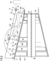
FIG. 2 is a schematic layout of the compressor of the gas turbine engine in accordance with the present invention and in an enlarged view, -
FIG. 3 is a graphical representation of the method of operating the gas turbine in accordance with the present invention, the graphical representation showing the general relationship between output power of the gas turbine engine along the x-axis and combustor temperature along the y-axis, in particular this graphical representation is for when the demanded load of the gas turbine engine is changed between a high output power and a low output power. -
FIG. 1 shows an example of agas turbine engine 10 in a sectional view. Thegas turbine engine 10 comprises, in flow series, aninlet 12, acompressor 14, acombustor 16 and aturbine 18 which are generally arranged in flow series and generally about and in the direction of a longitudinal orrotational axis 20. Thegas turbine engine 10 further comprises afirst shaft 22 which is rotatable about therotational axis 20 and which extends longitudinally through part of thegas turbine engine 10. Thefirst shaft 22 drivingly connects theturbine 18 to thecompressor 14. Theturbine 18 is sometimes known as the compressor-turbine or high-pressure turbine. Apower turbine 19 may be located downstream of the compressor-turbine 18. Thepower turbine 19 may be drivingly connected to aload 26 via asecond shaft 28. Alternatively thecompressor turbine 18 may be drivingly connected to theload 26 via a shaft. Anexhaust 30 is located downstream of the compressor-turbine 18 and downstream of thepower turbine 19. - In operation of the
gas turbine engine 10,air 24, which is taken in through theair inlet 12 is compressed by thecompressor section 14 and delivered to the combustor16. The combustor16 comprises an annular array of combustor chambers as is well known, alternatively thecombustor 16 can be a nannular combustor 16 having an otherwise generally conventional arrangement. The compressed air passing through thecompressor 14 enters a diffuser and is discharged from the diffuser into thecombustor 16 from where a portion of the air is mixed with a gaseous or liquid fuel. The air/fuel mixture is then burned and the combustion gas or working gas from the combustion is channelled through thecombustion chamber 16 to theturbine 18 via a transition duct. - The combustion gas from the
combustor 16 enters theturbine 18 and drives its turbine blades which in turn rotate theshaft 22 to drive thecompressor 14. Theturbine 18 may also drive theload 26 directly via a shaft. Although as shown inFIG. 1 the combustion gas or working gas passes from theturbine 18 into and through thepower turbine 19. Thepower turbine 19 then may drive theload 26 viashaft 28. Working gas from either thepower turbine 19 or compressor-turbine 18 passes into theexhaust 30 and then out to ambient. - The
gas turbine engine 10 further comprises two compressor bleed systems. A firstcompressor bleed system 32 comprises afirst duct 34 connecting adownstream part 36 of thecompressor 14 and anupstream part 38. Theupstream part 38 may be part of thecompressor 14 or theinlet 12. As will be apparent to the skilled person thedownstream part 36 of the compressor is usually at a higher pressure than theupstream part 38. Afirst valve 40 is located on theduct 34 and is operable to control the amount of compressor air bled from the downstream part and reinjected into theupstream part 38. In one embodiment thedownstream part 36 is theoutlet 56 of thecompressor 14 or just downstream of the final stage of thecompressor 14. Theupstream part 38 is aninlet 55 of thecompressor 14, but in other examples theupstream part 38 may be anywhere upstream of the bleed off-take or where thefirst duct 34 connects to thedownstream part 36 of thecompressor 14. - A second
compressor bleed system 33 comprises asecond duct 35 connecting thedownstream part 36 of thecompressor 14 and theexhaust 30. As will be apparent to the skilled person thedownstream part 36 of the compressor is at a higher pressure than theexhaust 30. Asecond valve 41 is located on theduct 35 and is operable to control the amount of compressor air bled from thedownstream part 36 and injected into theexhaust 30. - The
gas turbine engine 10 also comprises anengine control unit 42. Thegas turbine engine 10 further comprises atemperature sensor 44 arranged to measure or to calculate a value representing the temperature of thecombustor 16 and preferably of the combustion gas at anoutlet 45 of thecombustor 16. There may be onetemperature sensor 44 or an annular array oftemperature sensors 44 either mounted to each combustor unit in an array of combustor units or around an annular combustor, or thesensors 44 may be downstream from thecombustor outlet 45 and the temperature at theoutlet 45 is calculated within thecontrol unit 42 from these downstream measurements. Among other aspects of the gas turbine engine, theengine control unit 42 is connected to thefirst valve 40 of the firstcompressor bleed system 32,second valve 41 of the secondcompressor bleed system 33 and the temperature sensor(s) 44. Theengine control unit 42 is programmed with a set of instructions for operating thevalves 40, 41 (andvalves variable vane mechanism 49 during engine operation. - In general, restricting the air flow through the
compressor 14 and therefore thecombustor 16 maintains an acceptable fuel/air ratio and hence elevates or maintains a relatively high combustion temperature than would otherwise occur. Restricting the air flow through thecombustor 16 is achieved by reducing the pressure ratio across thecompressor 14 and therefore the amount of compressed air fed into thecombustor 16. When reducing power output, the present method varies the angle of thevariable guide vanes 46V from an open position to a closed position, then bleeds compressed air first via control of thefirst bleed system 32 and then bleeds more compressed air via thesecond bleed system 33. This method provides progressive and sequential management of reducing the pressure ratio across the compressor. - This method is applicable in both directions of power output or load i.e. decreasing power output and increasing power output. In other words when increasing output power the
second bleed system 33 is gradually decreased to a minimum, then thefirst bleed system 32 is gradually decreased to a minimum and finally thevariable guide vanes 46V are opened from a closed position. Operating or varying closing thevariable guide vanes 46V from a higher output power than the first andsecond bleed systems first bleed system 32, bleeding from the downstream part to the upstream part of the compressor is the more efficient bleed system because it has less impact on the thermal efficiency of the engine. Thefirst bleed system 32 effectively reduces the pressure of the compressor at its downstream part by bleeding compressed air and by injecting pressurized air into the upstream part increases its pressure thereby relatively efficiently reducing the pressure ratio across the compressor. The second bleed system is used after the first bleed system because it is less efficient in terms of thermal cycle of the engine as it dumps compressed air into the exhaust and loses much of the work done in compressing it in the first place. - Referring to
FIG. 2 , thecompressor 14 comprises an axial series of vane stages 46 and rotor blade stages 48. The rotor blade stages 48 comprise a rotor disc supporting an annular array of blades in conventional fashion. Thecompressor 14 also comprises acasing 50 that surrounds the rotor stages and supports the vane stages 46, 46V. The guide vane stages include an annular array of radially extending vanes that are mounted to thecasing 50. The vanes are provided to present gas flow at an optimal angle for the blades at a given engine operational point. Some of the guide vane stages 48V are variable guide vanes and havevariable vane mechanisms 49, where the angle of the vanes, about their own longitudinal axis, can be adjusted for angle according to air flow characteristics that can occur at a range of different engine operating conditions. Generally, as output power is increased the variable guide vanes 48V are rotated or angledvariable vane mechanisms 49 from an 'open' position towards a closed position. Thevariable guide vanes 46V and thevariable vane mechanisms 49 are of a conventional design. Thevariable vane mechanisms 49 is connected to an operated by theengine control unit 42. Thevariable vane mechanisms 49 have asensor 47 for determining the position or angle of thevariable vanes 46V and which is also connected to theengine control unit 42. - The
compressor 14 further comprises bleedoutlets casing 50 and which allows compressed air to be bled from thecompressor 14. Two bleed outlets are shown although one or at least 3 bleed outlets are possible. Eachbleed outlet bleed outlets bleed duct bleed outlet duct operable valve engine control unit 42.Bleed outlet 52 is preferably located at or near to theoutlet 56 of the compressor, but it can be located between stages of the compressor and downstream of thebleed outlet 54 when two bleed outlets or off-takes are employed. Where there is only one bleed outlet it is preferably bleedoutlet 52. Thebleed ducts first duct 34 andsecond duct 35. Alternatively, thebleed ducts 52A may connect to thesecond duct 35 and thebleed duct 54A may connect to thefirst duct 34. - The
gas turbine engine 10 may comprisevalve position sensors 57 on each of the first valve(s) 40 and second valve(s) 41 and indeedvalves valve position sensors 57 are connected to theengine control unit 42 so that it is known whether the valve is fully open or fully closed or a position between fully open and fully closed. Therefore, by calibrating the bleed system for air flow against valve position, the quantity of air being bled from the compressor is known at any desired time. Thus it is possible to match the valve position to the power output over the power output ranges 67R, 70R and 70R'. - Referring now to
FIG.3 , thex-axis scale 60 is the percentage output power relative to the maximum power attainable from the gas turbine engine at specific weather or ambient conditions at the inlet and particularly the inlet temperature and pressure. Alternatively, the x-axis scale could be engine output power with maximum power output (at point 64). The y-axis scale is temperature of the combustion gas at theoutlet 45 of thecombustor 16. Immediately, it is pointed out that for any given gas turbine engine and ambient conditions at theinlet 12 the temperature and percentage output power can be markedly different to those schematically shown and therefore the graphical representation is not to scale. - The method of operating the gas turbine engine is intended to follow the
operating line 63 which depicts the relationship between percentage output power and temperature at theoutlet 45 of thecombustor 16 as previously mentioned above. The operatingline 63 has a number ofpoints 64 to 73 and operating conditions or ranges which will now be described with reference to reducing the power output of the gas turbine engine from 100% to 0% maximum output power i.e. from top right of the graph to bottom left. However, it should be appreciated that the present method does not require the gas turbine engine to be at 100% nor end at 0%. It should be apparent that the method described here may comprise operation of the gas turbine engine during an increase in power output and between 0% (inclusive) and 100% (inclusive) i.e. from bottom left of the graph to top right of the graph or in other words increasing the output power of theengine 10. Furthermore, the present method only requires that the gas turbine can operate within the specified power output ranges where the variable guide vanes and/or the first bleed system and/or the second bleed system operate. -
Point 64 is 100% or maximum output power and thehighest combustor outlet 45 temperature. At this operational point thevariable guide vanes 46V are fully open and there is no bleed from thecompressor 14, here the temperature at theoutlet 45 of thecombustor 16 is sufficiently high that minimal or acceptable emissions are generated. -
Point 65 is in a highoutput power range 65R and is below 100% output power and the temperature measured at theoutlet 45 of thecombustor 16 is below the highest combustor outlet temperature.Point 65 represents a position on the graph between apoint 88 and thepoint 64 and is within the engine's highoutput power range 65R. The highoutput power range 65R includes 100% output power (point 64) and up topoint 88. Typically, the highoutput power range 65R is 100% maximum output power to 80% maximum output power. In other examples, the highoutput power range 65R is 100% maximum output power to 75% maximum output power. At the highoutput power range 65R thevariable guide vanes 46V are fully open and there is no bleed from thecompressor 14 and the temperature at theoutlet 45 of thecombustor 16 is still sufficiently high that minimal or acceptable emissions are generated. - At point 88 a third predetermined temperature T3 occurs and is within a medium-high
power output range 80R. The medium-highpower output range 80R extends frompoint 88 to apoint 84. When the third predetermined temperature T3 is measured by the temperature sensor, theengine control unit 42 begins to close thevariable guide vanes 46V via thevariable vane mechanisms 49. As the power output continues to decrease, thevariable guide vanes 46V rotational position is modulated, rotating between and in the direction from an open position and to a closed position, to maintain a constant temperature of the combustor or combustion flame temperature by virtue of reducing or controlling the amount to compressed air entering thecombustor 16. Atpoint 84 thevariable guide vanes 46V are at their most closed position for any given engine and/or ambient conditions. During the medium-highoutput power range 80R the method comprises varying the angle of thevariable guide vanes 46V so that a third predetermined temperature T3 of thecombustor 16 is maintained. The medium-highoutput power range 80R has amaximum point 88 and aminimum point 84. The method comprises varying the angle of thevariable guide vanes 46V so that the third predetermined temperature T3 of the combustor is maintained by varying the angle of thevariable guide vanes 46V between an open position at themaximum point 88 and a closed position at theminimum point 84. - At
point 84 thevariable guide vanes 46V are at their most closed position for any given engine and/or ambient conditions. Belowpoint 84 the gas turbine engine continues to reduce power and the temperature of the combustor reduces until apoint 66 is reached or occurs. Thistransitory power range 82R extends betweenpoint 84 andpoint 66 and thevariable guide vanes 46V remain fully closed. -
Point 66 is at a first predetermined temperature T1 and within a mediumoutput power range 67R of thegas turbine engine 10. Immediately abovepoint 66 there is no bleed from thecompressor 14 and this operating mode in as described with reference to point 65 above. Belowpoint 66 the temperature of the combustor's outlet might otherwise be below a temperature of the combustor where emissions would be undesirable or unacceptable. Within the mediumoutput power range 67R, e.g. atpoint 67, which is less than the medium-highoutput power range 80R, thecombustor 16 has a constant outlet temperature. Here, as the combustor or first outlet temperature reaches the first predetermined temperature T1, the method comprises bleeding the compressed gas from adownstream part 36 of thecompressor 14 to anupstream part 38 of thecompressor 14 so that the first outlet temperature is maintained. As the power output of the engine decreases from thepoint 66 and towardspoint 68 theengine control unit 42 commands the valve 40 (and whereapplicable valves 52B and/or 54B) to open and increase the amount of bleed to maintain the first outlet temperature at the first predetermined temperature T1. -
Point 68 represents the end of the mediumoutput power range 67R. Atpoint 68 bleeding the gas from adownstream part 36 of thecompressor 14 to anupstream part 38 of thecompressor 14 has reached a maximum and thevalve 40 is fully open. It should be appreciated that 'fully open' here may mean that the valve 40 (and where usedvalve 52B and/or 54B) is open to its maximum allowable extent depending on other parameters and engine application. For example, there may be another reason to limit the maximum allowable extent or 'fully open' state such as duct size or an operating limit such as maximum allowed inlet temperature to the compressor. Afterpoint 68 and as the output power decreases the temperature measured at theoutlet 45 of thecombustor 16 begins to decrease. -
Point 69 is where thegas turbine engine 10 begins operating at a mediumoutput power range 70R and where thecombustor 16 attains a second predetermined temperature T2 and, which in this example, is lower than the first predetermined temperature T1. Atpoint 69 theengine control unit 42 receives a signal from thetemperature sensor 44 to say that the second predetermined temperature T2 has been reached and commands the valve 41 (and where usedvalve 52B and/or 54B) to begin opening and to bleed the gas from thedownstream part 36 of thecompressor 14 to theexhaust 30 so that the second outlet temperature is maintained at second predetermined temperature T2. Atpoint 70, which is representative of a point within the medium-lowoutput power range 70R, thevariable guide vanes 46V are fully closed and bleeding the gas from adownstream part 36 of thecompressor 14 to anupstream part 38 of thecompressor 14 continues at a maximum and bleeding the gas from thedownstream part 36 of thecompressor 14 to theexhaust 30 is also occurring. Frompoint 69 and towardspoint 71 in the medium-lowpower output range 70R there is an increasing amount of bleeding the gas from thedownstream part 36 of thecompressor 14 to theexhaust 30. Theengine control unit 42 commands the valve 41 (and where usedvalve 52B and/or 54B) to gradually open an increasing amount and in relation to the decreasing engine output power so as to maintain the second predetermined temperature T2 at theoutlet 45 of thecombustor 16. When thevalve 41 is fully open to its maximum physical state or another limit is reached such as the maximum allowed exhaust temperature, atpoint 71, the maximum quantity of bleed gas is being bled from thecompressor 14 to theexhaust 30. Thus in the medium-lowoutput power range 70R there is maximum - or in an example not forming part of the claimed invention, at least a high quantity - of bleed gas being bled from thedownstream part 36 to theupstream part 38 of thecompressor 14 and a variable amount of bleed from thecompressor 14 to theexhaust 30. - The medium-low
output power range 70R extends betweenpoint 69 andpoint 71. Atpoint 69 effectively there is zero bleeding of the gas from thedownstream part 36 of thecompressor 14 to theexhaust 30, but it as this point thevalve 41 is about to be opened. Atpoint 71 the bleeding of the gas from thedownstream part 36 of thecompressor 14 to theexhaust 30 is at a maximum and thevariable guide vanes 46V are fully closed. - In a low
output power range 72R, which occurs betweenpoint 71 andpoint 73 which is 0% maximum output power, bleeding of the gas from thedownstream part 36 of thecompressor 14 to anupstream part 38 and to theexhaust 30 are both at a maximum. With no further bleed possible the temperature of theoutlet 45 of the combustor continues to fall with decreasing power output. Depending on the type of engine and ambient conditions the temperature of the combustor will be such that undesirable emissions will be generated; however, belowpoint 71 the engine is often being shut down and does not operate for significant amount of time. - Each of the third, first and second predetermined temperatures T3, T1, T2 comprises a nominal temperature and upper and lower limits. The upper and lower limits have variances from the nominal temperature typically of +5°C and -5°C respectively; this could also be called a temperature band of 10°C having a median which is the predetermined temperature. Other applications may have different temperature bands or limits e.g. 8°C temperature band or +4°C and -4°C. Changing the amount of gas bled from either the
first bleed system 32 or thesecond bleed system 33 depending on the operating power output comprises increasing or holding constant the amount of gas bled, by modulating the valve, if the temperature of thecombustor 16 reaches the lower limit and/or decreasing or holding constant the amount of gas bled, by modulating the valves, if the temperature of the combustor reaches the upper limit. Similarly, changing the rotational angle of thevariable guide vanes 46V depends on the operating power output and comprises increasing or holding constant the rotational angle, by modulating thevalve mechanism 49, if the temperature of thecombustor 16 reaches the lower limit and/or decreasing or holding constant the rotational angle, by modulating thevariable vane mechanism 49, if the temperature of the combustor reaches the upper limit. - The difference between the first predetermined temperature T1 and the second predetermined temperature T2 is approximately 5°C although in other examples of a gas turbine engine, which can have markedly different combustion systems, the difference between the first predetermined temperature T1 and the second predetermined temperature T2 may be in the range 5-20°C. However, as described above modulation of the
valves 40, 41 (and 52B, 54B) to control bleed mass flow is based on the combustor temperature reaching upper and lower limits, thus the temperature difference between T1 and T2 should be outside the upper and lower limits. The difference between the third predetermined temperature T3 and the first predetermined temperature T1 is approximately 10°C although in other examples of a gas turbine engine, which can have markedly different combustion systems, the difference between the third predetermined temperature T3 and the first predetermined temperature T1 may be in the range 5-20°C. However, as described above modulation of the rotational angle of thevariable guide vanes 46V is based on the combustor temperature reaching upper and lower limits, thus the temperature difference between third predetermined temperature T3 and the first predetermined temperature T1 should be outside the upper and lower limits. - In another example of the method of operating the
gas turbine engine 10, rather than using a temperature difference, i.e. the difference in temperature from predetermined temperature T1 to predetermined temperature T2, to initiate opening the valve 41 (and/orvalves downstream part 36 of thecompressor 14 to anupstream part 38 of thecompressor 14 has reached its maximum. One such indicator is the valve position sensor(s) 57 on the valve 40 (and if usedvalves downstream part 36 of thecompressor 14 to anupstream part 38 of thecompressor 14 has reached a predetermined amount or the maximum amount Thus inFigure 3 a modified method of operating the gas turbine engine is intended to follow the dashed part 63' of the operatingline 63 Operating points 70', 71', effectively replacepoints point 69 is obsolete. The medium-lowoutput power range 70R now becomes the medium-lowoutput power range 70R' and which extends betweenpoint 68 and point 71'. Thus first predetermined temperature T1 may equal or approximately equal second predetermined temperature T2. For any given gas turbine engine the medium-lowoutput power range 70R is approximately the same extent as the medium-lowoutput power range 70R'. - Alternatively or as well as, the valve position sensor(s) 57 on the valve 40 (and if used
valves engine control unit 42. Theengine control unit 42 is programmed such that when a predetermined valve position is reached, it commands thevalve 41 to begin opening. As output power or load is reduced in the medium-lowoutput power range 70R' theengine control unit 42 commands thevalve 41 to open in relatively increasing amounts thereby maintaining the outlet temperature of thecombustor 16 at predetermined temperatures T1 and/or T2. - Another such indicator is a
sensor 47 in thevariable vane mechanism 49 capable of indicating the rotational angle of thevariable guide vanes 46V and in particular when thevariable guide vanes 46V have reached their fully open and fully closed positions and indeed anywhere in between. Thus inFigure 3 a modified method of operating the gas turbine engine is intended to follow the dashedpart 63" of the operatingline 63.Points point 84 is obsolete. The medium-highoutput power range 80R now becomes the medium-highoutput power range 80R' and which extends between point 88' andpoint 66. Highoutput power range 65R becomes highoutput power range 65R' and may be slightly extended. Thus third predetermined temperature T3 may equal or approximately equal the first predetermined temperature T1. For any given gas turbine engine the medium-highoutput power range 80R is approximately the same extent as the medium-highoutput power range 80R'. As the power output decreases in the medium-highoutput power range 80R' thesensor 47 will continuously send signals to theengine control unit 42 to determine the rotational angle of thevariable guide vanes 46V. Atpoint 66 thesensor 47 signals to theengine control unit 42 that thevariable guide vanes 46V have reached their maximum closed position. Then, as soon as the temperature begins to decrease theengine control unit 42 indicates that thevalve 40 of thefirst bleed system 32 begins opening. - Similarly, if the power output increases in the medium
power output range 67R andpoint 66 is reached where thesensor 57 indicates the bleed valve 40 (and/or 52B, 54B) has closed then theengine control unit 42 will command thevariable vane mechanism 49 to begin rotating thevariable guide vanes 46V from their closed position towards their open position. - Thus it is possible that the third predetermined temperature T3 is the same as the first predetermined temperature T1. It is also possible that the third predetermined temperature T3 is the same as the first predetermined temperature T1 and the second predetermined temperature T2.
- When starting the gas turbine engine (point 73), as an example, and increasing the power output to 100% (point 64), both bleed
systems power output range 72R and thevariable guide vanes 46V are closed. An alternative approach to starting the gas turbine engine is to have one or both bleedsystems variable guide vanes 46V are open or partly open when starting and increasing the load until a specified point, within thelow power range 72R, is reached at which point both the first andsecond bleed systems variable guide vanes 46V are fully open. When the second predetermined temperature T2 of thecombustor 16 is reached thevalve 41 of thesecond bleed system 33 is commanded to begin closing from its fully opened state. As the power output continues to increase through the medium-lowpower output range valve 41 of thesecond bleed system 33 is commanded to gradually (smoothly or by steps) close untilpoint 69 orpoint 68 is reached depending whether there is a difference between T1 and T2 or T2=T1. - Where the second predetermined temperature T2 and the first predetermined temperature T1 are set with the difference as described above, the
power output line 63 is followed and on reachingpoint 69 thevalve 41 is fully closed. The temperature of thecombustor 16 increases from the second predetermined temperature T2 to the first predetermined temperature T1, over the shortpower output range 74R. When the first predetermined temperature T1 is reached thevalve 40 is commanded to begin closing from its fully opened or maximum allowable opened state. - Alternatively, where the second predetermined temperature T2 and the first predetermined temperature T1 are set to be approximately equal as described above, the power output line 63' is followed and on reaching
point 68 thevalve 41 is fully closed. The valve position sensor that monitorsvalve 41 signals thatvalve 41 is fully closed or very nearly closed, say within 5% closed, and theengine control unit 42 commands thevalve 40 to begin closing. - In either circumstance, as the power output continues to increase through the medium
power output range 67R thevalve 40 of thefirst bleed system 32 is commanded to gradually (smoothly or by steps) close untilpoint 66. - As described above the predetermined temperatures T1 and T2 are maintained at a constant nominal temperature (or at least within its upper and lower limits) through the medium-low
power output range output power range 67R by virtue of thetemperature sensor 44 indicating when an upper or lower limit is reached and modulating the valves to open or close an amount to compensate such that the combustor temperature remains within the predetermined temperature band. Similarly, the predetermined temperature T3 is maintained at a constant nominal temperature (or at least within its upper and lower limits) through the medium-highpower output range temperature sensor 44 indicating when an upper or lower limit is reached and modulating the angle of thevariable guide vanes 46V to open or close respectively an amount to compensate such that the combustor temperature remains within the predetermined temperature band or limits. - As will be apparent from the description relating to decreasing power output, during the high
power output range 65R bothvalves variable guide vanes 46V are fully open. - It should be appreciated that the values of the output power ranges 65R, 65R', 67R, 70R, 70R', 72R, 74R, 80R, 80R' and 82R or demanded load at points on the
operational lines second bleed system 32 is not operable (i.e. closed) and thevariable guide vanes 46V are closed within the mediumpower output range 67R. In other words, when decreasing engine power output thesecond bleed system 33 only commences bleeding once thefirst bleed system 32 has reached its maximum or very close to its maximum, e.g. within 5% of its maximum. Similarly, only when thevariable guide vanes 46V have reached their fully closed state is thefirst bleed system 32 operated. - In general, the medium-high
output power range 80R is between 90% to 40% maximum output power and preferably the medium-highoutput power range 80R is between 70% to 50% maximum output power. The mediumoutput power range 67R is between 90% to 40% maximum output power and preferably the mediumoutput power range 67R is between 70% to 50% maximum output power. The medium-lowoutput power range output power range 72R is between 0% and 45% maximum output power, preferably the lowoutput power range 72R is between 0% and 30% maximum output power, and more preferably the low output power range is between 0% and 25%. - In certain circumstances, particularly where the ambient temperature is extremely low, it is necessary to heat the air in the
inlet 12 and/or heat theinlet 12 for anti-icing purposes. In this circumstance the firstcompressor bleed system 32 may have further ducting to theinlet 12 and a portion of the compressor bleed is used for heating or anti-icing purposes. The remaining compressor bleed, which is the greater portion of the total available compressor bleed, is used by the firstcompressor bleed system 32 and the secondcompressor bleed system 34 as described herein. - The present invention is described with reference to the above exemplary turbine engine having a single shaft or spool connecting a single, multi-stage compressor and a single, one or more stage turbine. However, it should be appreciated that the present invention is equally applicable to two or three shaft engines and which can be used for industrial, aero or marine applications.
- The terms upstream and downstream refer to the flow direction of the airflow and/or working gas flow through the engine unless otherwise stated. The terms forward and rearward refer to the general flow of gas through the engine. The terms axial, radial and circumferential are made with reference to the
rotational axis 20 of the engine.
Claims (15)
- A method of controlling a gas turbine engine (10),the gas turbine engine (10) having in axial flow series a compressor (14), a combustor (16), a compressor-turbine (18) and an exhaust (30), the compressor (14) comprises variable guide vanes (46V), the gas turbine capable of operating in at least- a high output power range (65R),- a medium-high output power range (80R),- a medium output power range (67R),- a medium-low output power range (70R, 70R') and- a low output power range (72R),the method comprising the steps- during the medium-high output power range (80R) varying the angle of the variable guide vanes (46V) so that a third predetermined temperature (T3) of the combustor (16) is maintained,- during the medium output power range (67R) the variable guide vanes (46V) are at their most closed position and bleeding a gas from a downstream part (36) of the compressor (14) to an upstream part (38) of the compressor (14) so that a first predetermined temperature (T1) of the combustor (16) is maintained,- during the medium-low output power range (70R, 70R') the variable guide vanes (46V) are at their most closed position and bleeding a gas from a downstream part (36) of the compressor (14) to an upstream part (38) of the compressor (14) is a maximum and bleeding a gas from the downstream part (36) of the compressor (14) to the exhaust (30) so that a second predetermined temperature (T2) of the combustor (16) is maintained.
- A method of controlling a gas turbine engine (10) as claimed in claim 2 wherein,- during the low output power range (72R) the variable guide vanes (46V) are closed and bleeding a gas from a downstream part (36) of the compressor (14) to an upstream part (38) of the compressor (14) is at a maximum and bleeding a gas from the downstream part (36) of the compressor (14) to the exhaust (30) is at a maximum.
- A method of controlling a gas turbine engine (10) as claimed in any one of claims 1-2 wherein,- during the high output power range (65R) the variable guide vanes (46) are open and bleeding a gas from a downstream part (36) of the compressor (14) to an upstream part (38) of the compressor (14) is at a minimum or zero and bleeding a gas from the downstream part (36) of the compressor (14) to the exhaust (30) is at a minimum or zero.
- A method of controlling a gas turbine engine (10) as claimed in any one of claims 1-3 wherein,- during the medium-low output power range (70R, 70R') bleeding a gas from a downstream part (36) of the compressor (14) to an upstream part (38) of the compressor (14) is at a maximum.
- A method of controlling a gas turbine engine (10) as claimed in any one of claims 1-4 wherein,- the medium-high output power range (80R) has a maximum point (88) and a minimum point (84) and varying the angle of the variable guide vanes (46V) so that a third predetermined temperature (T3) of the combustor is maintained comprises varying the angle of the variable guide vanes (46V) between an open position at the maximum point (88) and a closed position at the minimum point (84).
- A method of controlling a gas turbine engine (10) as claimed in any one of claims 1-5 wherein,- the medium output power range (67R) has a maximum point (66) and a minimum point (68) and bleeding the gas from the downstream part (36) of the compressor (14) to the upstream part (38) of the compressor (14) comprises changing the amount of gas bled from a minimum amount at the maximum point (66) to a maximum amount at the minimum point (71, 71').
- A method of controlling a gas turbine engine (10) as claimed in any one of claims 1-6 wherein,- the medium-low output power range (70R, 70R') has a maximum point (68, 69) and a minimum point (71, 71') and bleeding a gas from the downstream part (36) of the compressor (14) to the exhaust (30) comprises changing the amount of gas bled from a minimum amount at the maximum point (68,69) to a maximum amount at the minimum point (71,71').
- A method of controlling a gas turbine engine (10) as claimed in any one of claims 6-7 wherein,- each of the third, first and second predetermined temperatures (T3, T1, T2) comprises a nominal temperature and upper and lower limits, preferably the upper and lower limits having variances from the nominal temperature of +5°C and -5°C respectively, and- changing the amount of gas bled comprises- increasing the amount of gas bled if the temperature of the combustor reaches the lower limit and/or- decreasing the amount of gas bled if the temperature of the combustor reaches the upper limit.
- A method of controlling a gas turbine engine (10) as claimed in any one of claims 1-8 wherein,- the difference between the first predetermined temperature (T1) and the second predetermined temperature (T2) is in the range 5-20°C and more preferably approximately 5°C and- the difference between the first predetermined temperature (T1) and the third predetermined temperature (T3) is in the range 5-20°C and more preferably approximately 10°C.
- A method of controlling a gas turbine engine (10) as claimed in any one of claims 1-9 wherein,- detecting the angle of the variable guide vanes (46V) has reached a maximum closed position and- starting bleeding a gas from the downstream part (36) of the compressor (14) to the upstream part (38).
- A method of controlling a gas turbine engine (10) as claimed in any one of claims 1-10 wherein,- detecting bleeding a gas from a downstream part (36) of the compressor (14) to an upstream part (38) of the compressor (14) has reached a maximum and- starting bleeding a gas from the downstream part (36) of the compressor (14) to the exhaust (30).
- A method of controlling a gas turbine engine (10) as claimed in any one of claims 1-11 wherein,- the high output power range (65R) is between 100% to 70% maximum output power, preferably the high output power range (65R) is between 100% to 80% maximum output power,- the medium-high output power range (80R) is between 90% to 40% maximum output power, preferably the medium-high output power range (80R) is between 70% to 50% maximum output power,- the medium output power range (67R) is between 90% to 40% maximum output power, preferably the medium output power range (67R) is between 70% to 50% maximum output power,- the medium-low output power range (70R, 70R') is between 50% to 35% maximum output power, and- the low output power range (72R) is between 0% and 45% maximum output power, preferably the low output power range (72R) is between 0% and 30% maximum output power, and more preferably the low output power range is between 0% and 25%.
- A gas turbine engine (10) capable of operating in at least a high output power range (65R), a medium-high output power range (80R), a medium output power range (67R), a medium-low output power range (70R, 70R') and a low output power range (72R), the gas turbine engine (10) comprising- in axial flow series a compressor (14), a combustor (16), a compressor-turbine (18) and an exhaust (30),- the compressor (14) comprises at least one stage of variable guide vanes (46V) having a variable vane mechanism (49),- a temperature sensor (44) mounted to the gas turbine engine (10) and arranged to sense or calculate the temperature of the combustor (16),- a first compressor bleed system (32) comprising a first duct (34) connecting a downstream part (36) of the compressor (14) and an upstream part (38) and a first valve (40) located on the duct (34),- a second compressor bleed system (33) comprises a second duct (35) connecting the downstream part (36) of the compressor (14) and the exhaust (30) and a second valve (41) located on the duct (35),- an engine control unit (42) connected to the temperature sensor (44), the first valve (40), the second valve (41) and the variable vane mechanism (49), the engine control unit (42) programmed to control the variable vane mechanism 49, the first valve (40) and the second valve (41) dependent on the temperature of the combustor (16) such that- during the medium-high output power range (80R) the at least one stage of variable guide vanes (46V) is at least partly open such that a third predetermined temperature (T3) of the combustor (16) is maintained,- during the medium output power range (67R) the variable guide vanes (46V) are at their most closed position and the first valve (40) is at least partly open such that a first predetermined temperature (T1) of the combustor (16) is maintained, and- during the medium-low output power range (70R, 70R') the variable guide vanes (46V) are at their most closed position and the second valve (41) is at least partly open and the first valve (40) is fully open such that a second predetermined temperature (T2) of the combustor (16) is maintained.
- A gas turbine engine (10) as claimed in claim 13, wherein the gas turbine engine (10) further comprises a power turbine (19) located between the turbine (18) and the exhaust (30), the power turbine (19) is connected to a shaft (28) for driving a load (26).
- A gas turbine engine (10) as claimed in any one of claims 13-14, wherein- the upstream part (38) is an inlet (55) of the compressor (14) and the downstream part (38) is at least the outlet (56) of the compressor (14),- the first compressor bleed system (32) and the second compressor bleed system (33) have a common first bleed outlet (52) or a common array of first bleed outlets (52) located at the outlet (56) of the compressor (14).
Applications Claiming Priority (2)
| Application Number | Priority Date | Filing Date | Title |
|---|---|---|---|
| EP17199218.3A EP3477080A1 (en) | 2017-10-30 | 2017-10-30 | Method of controlling a gas turbine engine |
| PCT/EP2018/078973 WO2019086293A1 (en) | 2017-10-30 | 2018-10-23 | Gas turbine engine and control method |
Publications (2)
| Publication Number | Publication Date |
|---|---|
| EP3704369A1 EP3704369A1 (en) | 2020-09-09 |
| EP3704369B1 true EP3704369B1 (en) | 2023-01-04 |
Family
ID=60201393
Family Applications (2)
| Application Number | Title | Priority Date | Filing Date |
|---|---|---|---|
| EP17199218.3A Withdrawn EP3477080A1 (en) | 2017-10-30 | 2017-10-30 | Method of controlling a gas turbine engine |
| EP18800493.1A Active EP3704369B1 (en) | 2017-10-30 | 2018-10-23 | Gas turbine engine and control method |
Family Applications Before (1)
| Application Number | Title | Priority Date | Filing Date |
|---|---|---|---|
| EP17199218.3A Withdrawn EP3477080A1 (en) | 2017-10-30 | 2017-10-30 | Method of controlling a gas turbine engine |
Country Status (6)
| Country | Link |
|---|---|
| US (1) | US11274608B2 (en) |
| EP (2) | EP3477080A1 (en) |
| CN (1) | CN111295503B (en) |
| CA (1) | CA3081649C (en) |
| RU (1) | RU2745185C1 (en) |
| WO (1) | WO2019086293A1 (en) |
Families Citing this family (10)
| Publication number | Priority date | Publication date | Assignee | Title |
|---|---|---|---|---|
| CN112912691A (en) | 2018-08-26 | 2021-06-04 | 航空电机工程有限公司 | Electromagnetic gyro stabilized propulsion system method and device |
| KR20210116532A (en) | 2019-01-20 | 2021-09-27 | 에어본 모터스, 엘엘씨 | Medical ballast harness method and device |
| US12546287B2 (en) | 2020-02-28 | 2026-02-10 | Airborne Motorworks Inc. | Sound vibration and friction limiting turbine generator gyroscope method and apparatus |
| JP2023516298A (en) * | 2020-02-28 | 2023-04-19 | エアーボーン モーター ワークス インク. | Friction-limited turbogenerator gyroscope method and apparatus |
| US11280496B2 (en) * | 2020-03-25 | 2022-03-22 | General Electric Company | Gas turbine engine and methods of controlling emissions therefrom |
| CN112627989A (en) * | 2021-01-08 | 2021-04-09 | 大连欧谱纳透平动力科技有限公司 | System and method for controlling exhaust temperature and nitrogen oxide concentration of small gas turbine |
| US11859500B2 (en) * | 2021-11-05 | 2024-01-02 | General Electric Company | Gas turbine engine with a fluid conduit system and a method of operating the same |
| CN116085067A (en) | 2021-11-05 | 2023-05-09 | 通用电气公司 | Gas turbine engine with fluid conduit system and method of operating the same |
| US12196141B2 (en) * | 2023-04-19 | 2025-01-14 | Honeywell International Inc. | Systems and methods with distributed bleed for gas turbine engine compressor stabilization |
| US12454919B2 (en) * | 2023-08-01 | 2025-10-28 | Power Systems Mfg., Llc | Exhaust cooling injection for improved turndown |
Family Cites Families (6)
| Publication number | Priority date | Publication date | Assignee | Title |
|---|---|---|---|---|
| ITMI20022757A1 (en) * | 2002-12-23 | 2004-06-24 | Nuovo Pignone Spa | EMISSION CONTROL AND OPTIMIZATION SYSTEM |
| US8015826B2 (en) * | 2007-04-05 | 2011-09-13 | Siemens Energy, Inc. | Engine brake for part load CO reduction |
| US9297316B2 (en) * | 2011-11-23 | 2016-03-29 | General Electric Company | Method and apparatus for optimizing the operation of a turbine system under flexible loads |
| EP2600063A3 (en) | 2013-02-19 | 2014-05-07 | Alstom Technology Ltd | Method of operating a gas turbine with staged and/or sequential combustion |
| TWI654368B (en) * | 2013-06-28 | 2019-03-21 | 美商艾克頌美孚上游研究公司 | System, method and media for controlling exhaust gas flow in an exhaust gas recirculation gas turbine system |
| JP6190670B2 (en) * | 2013-08-30 | 2017-08-30 | 三菱日立パワーシステムズ株式会社 | Gas turbine combustion system |
-
2017
- 2017-10-30 EP EP17199218.3A patent/EP3477080A1/en not_active Withdrawn
-
2018
- 2018-10-23 US US16/753,827 patent/US11274608B2/en active Active
- 2018-10-23 RU RU2020117511A patent/RU2745185C1/en active
- 2018-10-23 CN CN201880071019.1A patent/CN111295503B/en active Active
- 2018-10-23 EP EP18800493.1A patent/EP3704369B1/en active Active
- 2018-10-23 WO PCT/EP2018/078973 patent/WO2019086293A1/en not_active Ceased
- 2018-10-23 CA CA3081649A patent/CA3081649C/en active Active
Also Published As
| Publication number | Publication date |
|---|---|
| CA3081649A1 (en) | 2019-05-09 |
| US11274608B2 (en) | 2022-03-15 |
| WO2019086293A1 (en) | 2019-05-09 |
| US20200291871A1 (en) | 2020-09-17 |
| CA3081649C (en) | 2022-05-17 |
| EP3704369A1 (en) | 2020-09-09 |
| EP3477080A1 (en) | 2019-05-01 |
| CN111295503B (en) | 2023-04-14 |
| RU2745185C1 (en) | 2021-03-22 |
| CN111295503A (en) | 2020-06-16 |
Similar Documents
| Publication | Publication Date | Title |
|---|---|---|
| US11274608B2 (en) | Gas turbine engine and control method | |
| EP1770331B1 (en) | Method of controlling bypass air split to gas turbine combustor | |
| EP2650504B1 (en) | Method, system and apparatus relating to combustion turbine power plants with exhaust gas recirculation | |
| AU2010323284B2 (en) | Exhaust temperature versus turbine pressure ratio based turbine control method and device | |
| AU2010323281B2 (en) | Exhaust temperature based threshold for control method and turbine | |
| EP2504546B1 (en) | Exhaust temperature based mode control method for gas turbine and gas turbine | |
| US20130269310A1 (en) | Systems and apparatus relating to reheat combustion turbine engines with exhaust gas recirculation | |
| US20130269358A1 (en) | Methods, systems and apparatus relating to reheat combustion turbine engines with exhaust gas recirculation | |
| US20130269361A1 (en) | Methods relating to reheat combustion turbine engines with exhaust gas recirculation | |
| KR20010007259A (en) | Method of operation of industrial gas turbine for optimal performance | |
| US20130269311A1 (en) | Systems and apparatus relating to reheat combustion turbine engines with exhaust gas recirculation | |
| CA2762868C (en) | Gas turbine engine with bleed air system | |
| US11739697B2 (en) | Bleed flow safety system | |
| US10408217B2 (en) | Controlling a compressor of a gas turbine engine | |
| EP2846022A1 (en) | Gas turbine combustion system | |
| CN111664010A (en) | Predictive health management control for adaptive operability restoration of turbine engines | |
| EP1746347A2 (en) | Method and system for operating a multi-stage combustor | |
| US11365689B2 (en) | Method of controlling a gas turbine engine | |
| US20160312649A1 (en) | High performance robust gas turbine exhaust with variable (adaptive) exhaust diffuser geometry |
Legal Events
| Date | Code | Title | Description |
|---|---|---|---|
| STAA | Information on the status of an ep patent application or granted ep patent |
Free format text: STATUS: UNKNOWN |
|
| STAA | Information on the status of an ep patent application or granted ep patent |
Free format text: STATUS: THE INTERNATIONAL PUBLICATION HAS BEEN MADE |
|
| PUAI | Public reference made under article 153(3) epc to a published international application that has entered the european phase |
Free format text: ORIGINAL CODE: 0009012 |
|
| STAA | Information on the status of an ep patent application or granted ep patent |
Free format text: STATUS: REQUEST FOR EXAMINATION WAS MADE |
|
| 17P | Request for examination filed |
Effective date: 20200331 |
|
| AK | Designated contracting states |
Kind code of ref document: A1 Designated state(s): AL AT BE BG CH CY CZ DE DK EE ES FI FR GB GR HR HU IE IS IT LI LT LU LV MC MK MT NL NO PL PT RO RS SE SI SK SM TR |
|
| AX | Request for extension of the european patent |
Extension state: BA ME |
|
| RAP1 | Party data changed (applicant data changed or rights of an application transferred) |
Owner name: SIEMENS ENERGY GLOBAL GMBH & CO. KG |
|
| DAV | Request for validation of the european patent (deleted) | ||
| DAX | Request for extension of the european patent (deleted) | ||
| GRAP | Despatch of communication of intention to grant a patent |
Free format text: ORIGINAL CODE: EPIDOSNIGR1 |
|
| STAA | Information on the status of an ep patent application or granted ep patent |
Free format text: STATUS: GRANT OF PATENT IS INTENDED |
|
| INTG | Intention to grant announced |
Effective date: 20220729 |
|
| GRAS | Grant fee paid |
Free format text: ORIGINAL CODE: EPIDOSNIGR3 |
|
| GRAA | (expected) grant |
Free format text: ORIGINAL CODE: 0009210 |
|
| STAA | Information on the status of an ep patent application or granted ep patent |
Free format text: STATUS: THE PATENT HAS BEEN GRANTED |
|
| AK | Designated contracting states |
Kind code of ref document: B1 Designated state(s): AL AT BE BG CH CY CZ DE DK EE ES FI FR GB GR HR HU IE IS IT LI LT LU LV MC MK MT NL NO PL PT RO RS SE SI SK SM TR |
|
| REG | Reference to a national code |
Ref country code: GB Ref legal event code: FG4D |
|
| REG | Reference to a national code |
Ref country code: CH Ref legal event code: EP |
|
| REG | Reference to a national code |
Ref country code: AT Ref legal event code: REF Ref document number: 1542086 Country of ref document: AT Kind code of ref document: T Effective date: 20230115 |
|
| REG | Reference to a national code |
Ref country code: DE Ref legal event code: R096 Ref document number: 602018045085 Country of ref document: DE |
|
| REG | Reference to a national code |
Ref country code: IE Ref legal event code: FG4D |
|
| REG | Reference to a national code |
Ref country code: LT Ref legal event code: MG9D |
|
| REG | Reference to a national code |
Ref country code: NL Ref legal event code: MP Effective date: 20230104 |
|
| REG | Reference to a national code |
Ref country code: AT Ref legal event code: MK05 Ref document number: 1542086 Country of ref document: AT Kind code of ref document: T Effective date: 20230104 |
|
| PG25 | Lapsed in a contracting state [announced via postgrant information from national office to epo] |
Ref country code: NL Free format text: LAPSE BECAUSE OF FAILURE TO SUBMIT A TRANSLATION OF THE DESCRIPTION OR TO PAY THE FEE WITHIN THE PRESCRIBED TIME-LIMIT Effective date: 20230104 |
|
| PG25 | Lapsed in a contracting state [announced via postgrant information from national office to epo] |
Ref country code: RS Free format text: LAPSE BECAUSE OF FAILURE TO SUBMIT A TRANSLATION OF THE DESCRIPTION OR TO PAY THE FEE WITHIN THE PRESCRIBED TIME-LIMIT Effective date: 20230104 Ref country code: PT Free format text: LAPSE BECAUSE OF FAILURE TO SUBMIT A TRANSLATION OF THE DESCRIPTION OR TO PAY THE FEE WITHIN THE PRESCRIBED TIME-LIMIT Effective date: 20230504 Ref country code: NO Free format text: LAPSE BECAUSE OF FAILURE TO SUBMIT A TRANSLATION OF THE DESCRIPTION OR TO PAY THE FEE WITHIN THE PRESCRIBED TIME-LIMIT Effective date: 20230404 Ref country code: LV Free format text: LAPSE BECAUSE OF FAILURE TO SUBMIT A TRANSLATION OF THE DESCRIPTION OR TO PAY THE FEE WITHIN THE PRESCRIBED TIME-LIMIT Effective date: 20230104 Ref country code: LT Free format text: LAPSE BECAUSE OF FAILURE TO SUBMIT A TRANSLATION OF THE DESCRIPTION OR TO PAY THE FEE WITHIN THE PRESCRIBED TIME-LIMIT Effective date: 20230104 Ref country code: HR Free format text: LAPSE BECAUSE OF FAILURE TO SUBMIT A TRANSLATION OF THE DESCRIPTION OR TO PAY THE FEE WITHIN THE PRESCRIBED TIME-LIMIT Effective date: 20230104 Ref country code: ES Free format text: LAPSE BECAUSE OF FAILURE TO SUBMIT A TRANSLATION OF THE DESCRIPTION OR TO PAY THE FEE WITHIN THE PRESCRIBED TIME-LIMIT Effective date: 20230104 Ref country code: AT Free format text: LAPSE BECAUSE OF FAILURE TO SUBMIT A TRANSLATION OF THE DESCRIPTION OR TO PAY THE FEE WITHIN THE PRESCRIBED TIME-LIMIT Effective date: 20230104 |
|
| PG25 | Lapsed in a contracting state [announced via postgrant information from national office to epo] |
Ref country code: SE Free format text: LAPSE BECAUSE OF FAILURE TO SUBMIT A TRANSLATION OF THE DESCRIPTION OR TO PAY THE FEE WITHIN THE PRESCRIBED TIME-LIMIT Effective date: 20230104 Ref country code: PL Free format text: LAPSE BECAUSE OF FAILURE TO SUBMIT A TRANSLATION OF THE DESCRIPTION OR TO PAY THE FEE WITHIN THE PRESCRIBED TIME-LIMIT Effective date: 20230104 Ref country code: IS Free format text: LAPSE BECAUSE OF FAILURE TO SUBMIT A TRANSLATION OF THE DESCRIPTION OR TO PAY THE FEE WITHIN THE PRESCRIBED TIME-LIMIT Effective date: 20230504 Ref country code: GR Free format text: LAPSE BECAUSE OF FAILURE TO SUBMIT A TRANSLATION OF THE DESCRIPTION OR TO PAY THE FEE WITHIN THE PRESCRIBED TIME-LIMIT Effective date: 20230405 Ref country code: FI Free format text: LAPSE BECAUSE OF FAILURE TO SUBMIT A TRANSLATION OF THE DESCRIPTION OR TO PAY THE FEE WITHIN THE PRESCRIBED TIME-LIMIT Effective date: 20230104 |
|
| REG | Reference to a national code |
Ref country code: DE Ref legal event code: R097 Ref document number: 602018045085 Country of ref document: DE |
|
| PG25 | Lapsed in a contracting state [announced via postgrant information from national office to epo] |
Ref country code: SM Free format text: LAPSE BECAUSE OF FAILURE TO SUBMIT A TRANSLATION OF THE DESCRIPTION OR TO PAY THE FEE WITHIN THE PRESCRIBED TIME-LIMIT Effective date: 20230104 Ref country code: RO Free format text: LAPSE BECAUSE OF FAILURE TO SUBMIT A TRANSLATION OF THE DESCRIPTION OR TO PAY THE FEE WITHIN THE PRESCRIBED TIME-LIMIT Effective date: 20230104 Ref country code: EE Free format text: LAPSE BECAUSE OF FAILURE TO SUBMIT A TRANSLATION OF THE DESCRIPTION OR TO PAY THE FEE WITHIN THE PRESCRIBED TIME-LIMIT Effective date: 20230104 Ref country code: DK Free format text: LAPSE BECAUSE OF FAILURE TO SUBMIT A TRANSLATION OF THE DESCRIPTION OR TO PAY THE FEE WITHIN THE PRESCRIBED TIME-LIMIT Effective date: 20230104 Ref country code: CZ Free format text: LAPSE BECAUSE OF FAILURE TO SUBMIT A TRANSLATION OF THE DESCRIPTION OR TO PAY THE FEE WITHIN THE PRESCRIBED TIME-LIMIT Effective date: 20230104 |
|
| PLBE | No opposition filed within time limit |
Free format text: ORIGINAL CODE: 0009261 |
|
| STAA | Information on the status of an ep patent application or granted ep patent |
Free format text: STATUS: NO OPPOSITION FILED WITHIN TIME LIMIT |
|
| PG25 | Lapsed in a contracting state [announced via postgrant information from national office to epo] |
Ref country code: SK Free format text: LAPSE BECAUSE OF FAILURE TO SUBMIT A TRANSLATION OF THE DESCRIPTION OR TO PAY THE FEE WITHIN THE PRESCRIBED TIME-LIMIT Effective date: 20230104 |
|
| 26N | No opposition filed |
Effective date: 20231005 |
|
| PG25 | Lapsed in a contracting state [announced via postgrant information from national office to epo] |
Ref country code: SI Free format text: LAPSE BECAUSE OF FAILURE TO SUBMIT A TRANSLATION OF THE DESCRIPTION OR TO PAY THE FEE WITHIN THE PRESCRIBED TIME-LIMIT Effective date: 20230104 |
|
| PG25 | Lapsed in a contracting state [announced via postgrant information from national office to epo] |
Ref country code: MC Free format text: LAPSE BECAUSE OF FAILURE TO SUBMIT A TRANSLATION OF THE DESCRIPTION OR TO PAY THE FEE WITHIN THE PRESCRIBED TIME-LIMIT Effective date: 20230104 |
|
| REG | Reference to a national code |
Ref country code: CH Ref legal event code: PL |
|
| REG | Reference to a national code |
Ref country code: BE Ref legal event code: MM Effective date: 20231031 |
|
| PG25 | Lapsed in a contracting state [announced via postgrant information from national office to epo] |
Ref country code: LU Free format text: LAPSE BECAUSE OF NON-PAYMENT OF DUE FEES Effective date: 20231023 |
|
| PG25 | Lapsed in a contracting state [announced via postgrant information from national office to epo] |
Ref country code: LU Free format text: LAPSE BECAUSE OF NON-PAYMENT OF DUE FEES Effective date: 20231023 |
|
| PG25 | Lapsed in a contracting state [announced via postgrant information from national office to epo] |
Ref country code: CH Free format text: LAPSE BECAUSE OF NON-PAYMENT OF DUE FEES Effective date: 20231031 |
|
| PG25 | Lapsed in a contracting state [announced via postgrant information from national office to epo] |
Ref country code: CH Free format text: LAPSE BECAUSE OF NON-PAYMENT OF DUE FEES Effective date: 20231031 |
|
| PG25 | Lapsed in a contracting state [announced via postgrant information from national office to epo] |
Ref country code: BE Free format text: LAPSE BECAUSE OF NON-PAYMENT OF DUE FEES Effective date: 20231031 |
|
| PG25 | Lapsed in a contracting state [announced via postgrant information from national office to epo] |
Ref country code: IE Free format text: LAPSE BECAUSE OF NON-PAYMENT OF DUE FEES Effective date: 20231023 |
|
| PG25 | Lapsed in a contracting state [announced via postgrant information from national office to epo] |
Ref country code: IE Free format text: LAPSE BECAUSE OF NON-PAYMENT OF DUE FEES Effective date: 20231023 |
|
| PG25 | Lapsed in a contracting state [announced via postgrant information from national office to epo] |
Ref country code: BG Free format text: LAPSE BECAUSE OF FAILURE TO SUBMIT A TRANSLATION OF THE DESCRIPTION OR TO PAY THE FEE WITHIN THE PRESCRIBED TIME-LIMIT Effective date: 20230104 |
|
| PG25 | Lapsed in a contracting state [announced via postgrant information from national office to epo] |
Ref country code: BG Free format text: LAPSE BECAUSE OF FAILURE TO SUBMIT A TRANSLATION OF THE DESCRIPTION OR TO PAY THE FEE WITHIN THE PRESCRIBED TIME-LIMIT Effective date: 20230104 |
|
| PG25 | Lapsed in a contracting state [announced via postgrant information from national office to epo] |
Ref country code: CY Free format text: LAPSE BECAUSE OF FAILURE TO SUBMIT A TRANSLATION OF THE DESCRIPTION OR TO PAY THE FEE WITHIN THE PRESCRIBED TIME-LIMIT; INVALID AB INITIO Effective date: 20181023 |
|
| PG25 | Lapsed in a contracting state [announced via postgrant information from national office to epo] |
Ref country code: HU Free format text: LAPSE BECAUSE OF FAILURE TO SUBMIT A TRANSLATION OF THE DESCRIPTION OR TO PAY THE FEE WITHIN THE PRESCRIBED TIME-LIMIT; INVALID AB INITIO Effective date: 20181023 |
|
| PG25 | Lapsed in a contracting state [announced via postgrant information from national office to epo] |
Ref country code: TR Free format text: LAPSE BECAUSE OF FAILURE TO SUBMIT A TRANSLATION OF THE DESCRIPTION OR TO PAY THE FEE WITHIN THE PRESCRIBED TIME-LIMIT Effective date: 20230104 |
|
| PGFP | Annual fee paid to national office [announced via postgrant information from national office to epo] |
Ref country code: DE Payment date: 20251028 Year of fee payment: 8 |
|
| PGFP | Annual fee paid to national office [announced via postgrant information from national office to epo] |
Ref country code: GB Payment date: 20251023 Year of fee payment: 8 |
|
| PGFP | Annual fee paid to national office [announced via postgrant information from national office to epo] |
Ref country code: IT Payment date: 20251022 Year of fee payment: 8 |
|
| PGFP | Annual fee paid to national office [announced via postgrant information from national office to epo] |
Ref country code: FR Payment date: 20251027 Year of fee payment: 8 |